Swirled Jet Flame Simulation and Flow Visualization Inside Rotary Kiln—CFD with PDF Approach
by
 ,
,
Hassan F. Elattar
1,2,* ,
,
Eckehard Specht
3,
Ali Fouda
1,4,
Saeed Rubaiee
1,5,
Ahmed Al-Zahrani
1 and
Sameh A. Nada
2,6 1
Department of Mechanical and Materials Engineering, Faculty of Engineering, University of Jeddah, Jeddah 21589, Saudi Arabia
2
Department of Mechanical Engineering, Benha Faculty of Engineering, Benha University, Benha, Qalyubia 13511, Egypt
3
Institute of Fluid Dynamics and Thermodynamics, Otto-von-Guericke-University of Magdeburg, Universitätsplatz 2, 39106 Magdeburg, Germany
4
Department of Mechanical Power Engineering, Faculty of Engineering, Mansoura University, El-Mansoura 35516, Egypt
5
Department of Industrial and Systems Engineering, Faculty of Engineering, University of Jeddah, Jeddah 21589, Saudi Arabia
6
Egypt-Japan University of Science and Technology, New Borg El-Arab City, Alexandria 21934, Egypt
*
Author to whom correspondence should be addressed.
Processes 2020, 8(2), 159; https://doi.org/10.3390/pr8020159
Submission received: 29 December 2019
/
Revised: 21 January 2020
/
Accepted: 22 January 2020
/
Published: 29 January 2020
(This article belongs to the Special Issue CFD Applications in Energy Engineering Research and Simulation)
Abstract
:CFD (computational fluid dynamics) simulation using a commercial package (Fluent-ANSYS) on industrial rotary kilns using annulus-type burners and methane gas was carried out to examine the characteristics of the flame length and flow visualization. New influencing design and operating parameters—primary air swirl number, primary air inlet annulus diameter, and secondary air temperature—were investigated and discussed. The influence of these parameters on axial temperature distribution, axial mean mixture fractions, velocity vectors, mixture fractions, and temperature contours were investigated. The current numerical findings were compared with existing experimental results to validate the simulation approach. The results showed that the primary air swirl number had a remarkable influence on the flame length at a lower primary air inlet annulus diameter ratio of 2.3. Moreover, the flame length increased by 20% and 6% with increasing the swirl number from zero to one for primary air inlet annulus diameter ratios of 2.3 and 5, respectively, and it also increased by 19% with increasing primary air inlet annulus diameter ratio from 2.3 to 5.
1. Introduction
Rotary kiln is a rotated cylinder lined with refractory material and is slightly axially inclined for the production of cement or other materials. Basically, rotary kilns can be considered as heat exchangers in which heat is liberated from combustion gases through the solid material and produces cement [1]. Rotary kilns are used in several industrial applications comprising lime and cement firing [2], petroleum coke calcination [3], and aluminum oxide calcination [4,5]. Cement production is considered to be dominated by the use of rotary kilns. Moreover, rotary kilns are widely utilized in waste incineration, as it can provide different kinds of waste solids and it can incinerate them effectively [6].
Over the last several years, the CFD (computational fluid dynamics) technique as a useful tool was implemented strongly for problems concerned with the effects of operating conditions and geometric parameters on rotary kiln performance. In the design stage, the flame heat transfer rate to materials has a vital influence on the kiln performance. The flame characteristics (i.e., length, maximum temperature, and shape) play significant role in the kiln performance, which influence significantly the heat transfer rate, the product quality, the lining material life time, and the emissions. The flame instability may lead to a large deviation in combustion gas temperatures, where the short flame can destroy the lining material and the long flame may not be capable of liberating sufficient heat to complete the chemical reaction. The operating variables such as kind and flow rate of fuel have a remarkable influence on the flame characteristics [7]. Because of the variation in the kiln operating variables, the research on the flame behavior is challenging to study [8,9,10,11]. Elattar et al. [8] presented a two-dimensional simulation to explain the influence of rotary kiln main operating and construction parameters on the flame characteristics, including heat and fluid flow using gaseous fuels (CH4, CO, and Biogas). Elattar [9] developed flame length numerical correlations for rotary kilns as a function of excess-air factor, diameter of air inlet, and kind of fuel, which have considerable influence on the flame behavior.
The impacts of primary air ratio, geometry of the burner (annulus type), and burner powers (i.e., several jet momentums of the fuel) on the flow field and kiln wall peak temperature were numerically investigated by Elattar et al. [10] using methane fuel. Nada et al. [11] studied the flow field and mixing characteristics of outwardly injected jets into a cross flow in a cylindrical chamber simulating the flow filed in Kiln burner. Khoei et al. [12] presented a mathematical simulation including heat transfer and fluid flow to find and enhance the temperature distributions inside the rotary kiln using the ELFEN finite element package. Mastorakos et al. [13] presented CFD modeling for rotary kilns used in cement production including heat transfer, flame shape, and clinker chemistry simulations using CFD commercial code and the Monte Carlo technique for radiation modelling. It was observed that radiation is the dominant heat-transfer mode from combustion gases to kiln walls, and heat losses across kiln walls is about 10%. Marias [14] presented a study using CFD simulation for the kiln gaseous phase and the postcombustion chamber including turbulence, combustion, and radiation, using natural gas fuel. The model was capable of expecting the radiation received by kiln walls and the volatile matter combustion.
Most of the industrial kilns use annulus burners for flame stability. Moreover, the secondary air is used in the kiln to reduce the overall kiln energy consumption by recuperating the heat from the charge to the kiln again, in addition to supplying the oxygen required in the combustion process. Furthermore, the swirl of primary air plays an important role in kiln flame stability and service life time of burner tips, as well as the refractory wall. Khalil et al. [15] studied experimentally the flow field of swirl confined/unconfined flames. It was found that confinement improves recirculation for both reacting and nonreacting flow. Moreover, the turbulence intensity and recirculation strength improved by flame confinement cause the increase of the Reynolds number. Elbaz and Roberts [16] examined experimentally the influence of quarl geometry on the flame shape of swirling CH4 for un-pre-mixed combustion, which represents a significant parameter in industrial burners and gas turbine applications. It was found that air swirling and quarl geometry considerably affects flame structure and flow shape, flame stability, and emissions. Elbaz and Roberts [17] experimentally studied flow field of non-pre-mixed swirled CH4 flames settled in quartz quarl by measuring the flow field instantaneously. Two different flames (i.e., two different fuel-jet velocities) were tested. The results showed a couple of vortex regions appeared at quarl exit corners at low fuel-jet velocity, while in the high fuel-jet velocity, additional downstream vortex collapsing varies the flame sheet path close to the central flame region.
The above literature review showed that investigations on flame geometry (shape and length), gas temperature, and flow field in rotary kilns are not completely covered. Several operating/design parameters relating to rotary kilns are still under study like primary air swirl number (Sn), primary air inlet annulus diameter ratio (dp/do), and secondary air temperature (Tsa) on the flame length characteristic. Therefore, the current work is conducted in order to examine and discuss the influence of swirl number and annulus diameter of the primary inlet air and temperature of the secondary air on the flame length characteristic, which directly affects the thermal processes and consequently the product’s quality throughout the rotary kiln.
2. Physical Model, Grid Generation, and Boundary Conditions
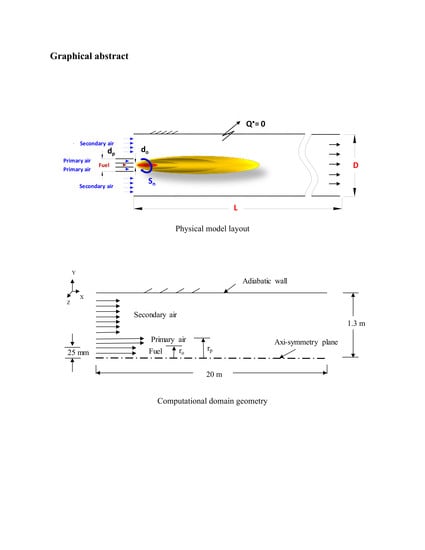
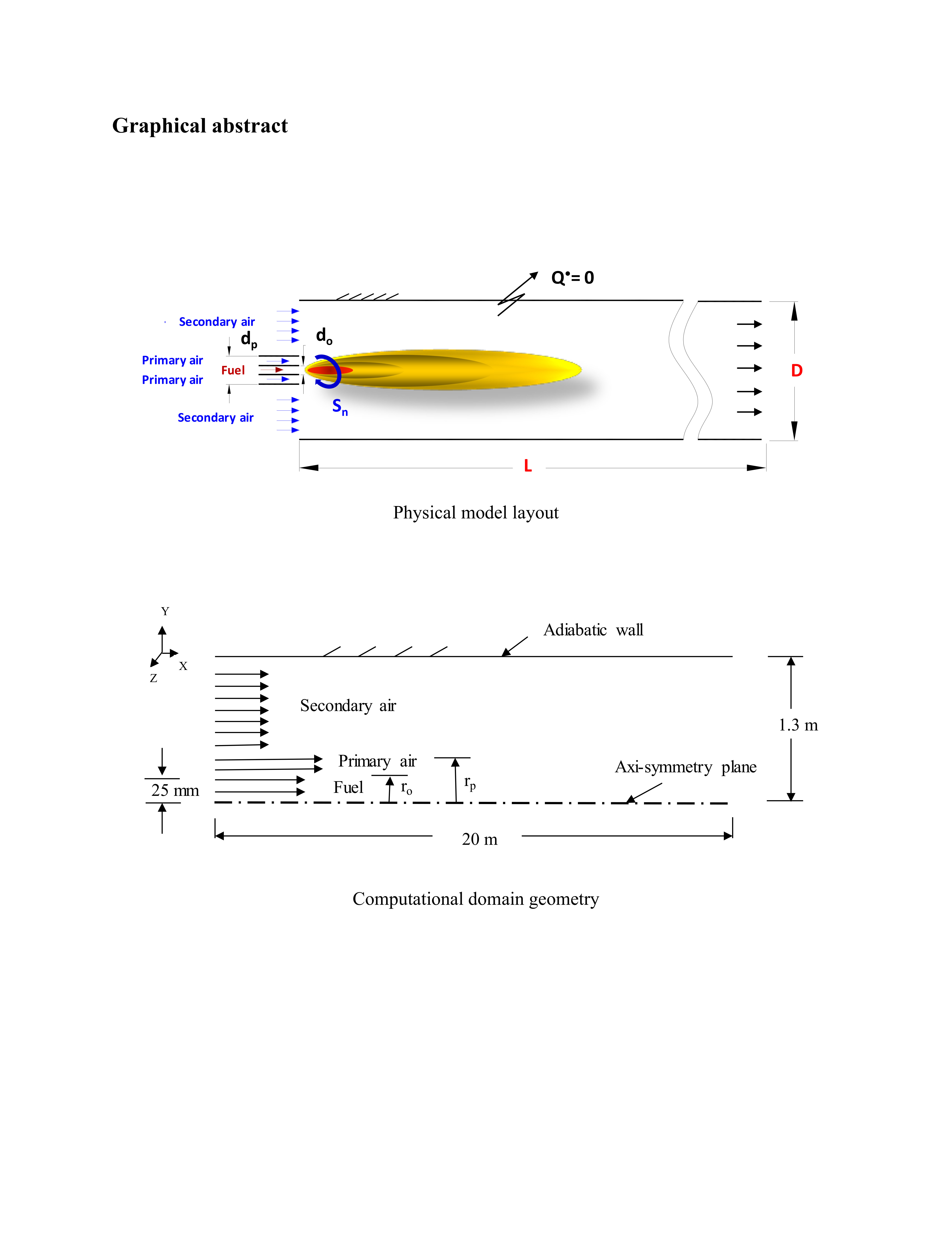
For studying the effects of kiln operating conditions and geometric parameters of the burner on flame length, the physical model of the simulated kiln was developed as schematically shown in Figure 1. The kiln diameter and length was 2.6 and 20 m, respectively, and it was fully opened for secondary air (i.e., secondary air inlet diameter ratio, da,i/D = 1). The kiln was operated by a pilot annulus tube burner using methane fuel having uniform axial velocity of 30 m/s with 20 °C and 1.975 MW burner thermal powers. The fuel nozzle diameter, primary air ratio, and excess air number were assumed do = 50 mm, α = 0.1, and λ = 1.3, respectively. The studied parameters are—swirl number of primary air (Sn = 0, 0.3, 0.5, 0.7, and 1), primary air inlet annulus diameter ratio (dp/do = 2.3 and 5) and secondary air temperature (Tsa = 20, 200, 400, 600, 800, and 1000 °C). A comparison between 2-D and 3-D simulation studies was carried out by Elattar [9] as an earliest step to present the maximum errors. The maximum error refers to the maximum deviation between the calculated variables obtained from 2-D and 3-D simulations throughout the computational domain. The results showed that the maximum error in axial velocity, axial temperature, and centerline mixture-fraction profiles were 5%, 2%, and 6%, respectively. So, for time and cost savings, 2-D axisymmetric simulation was preferred to fulfill the current work within acceptable errors.
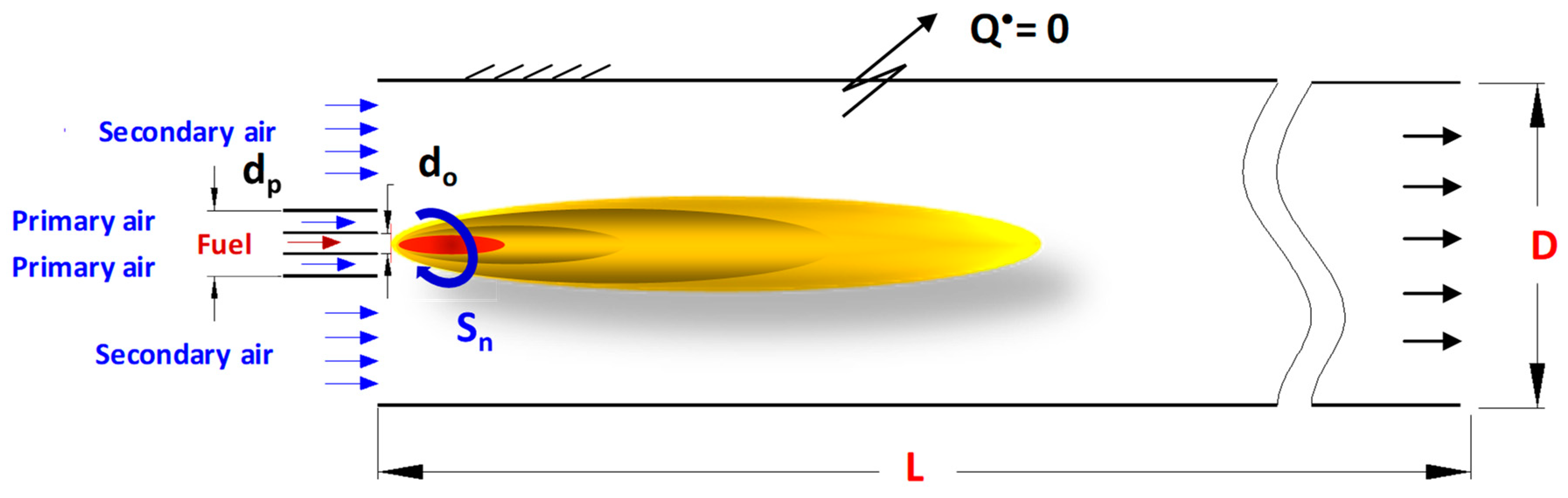
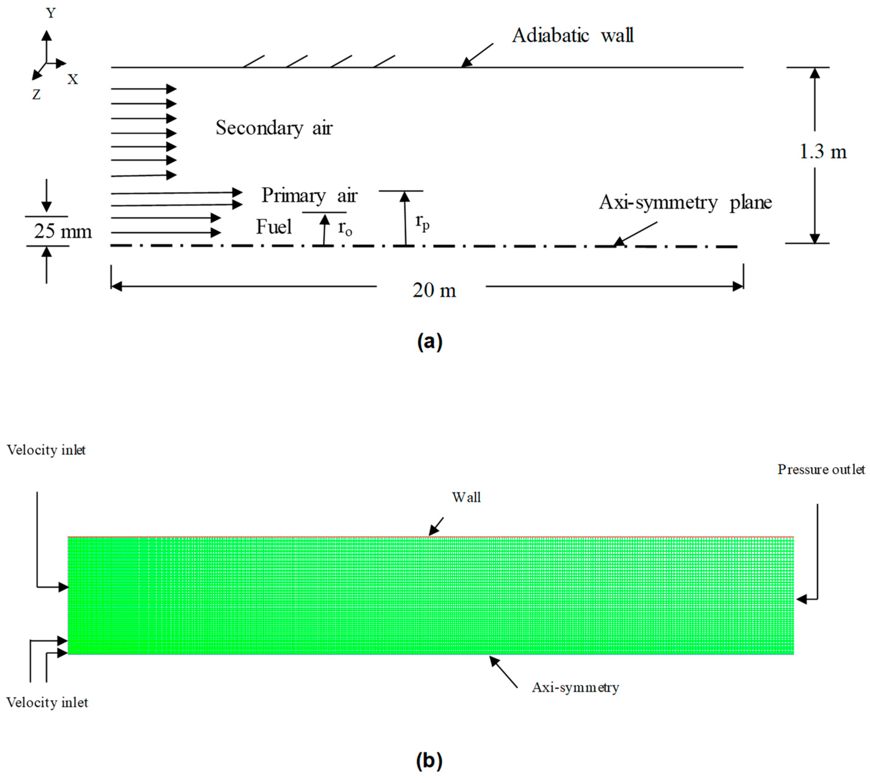
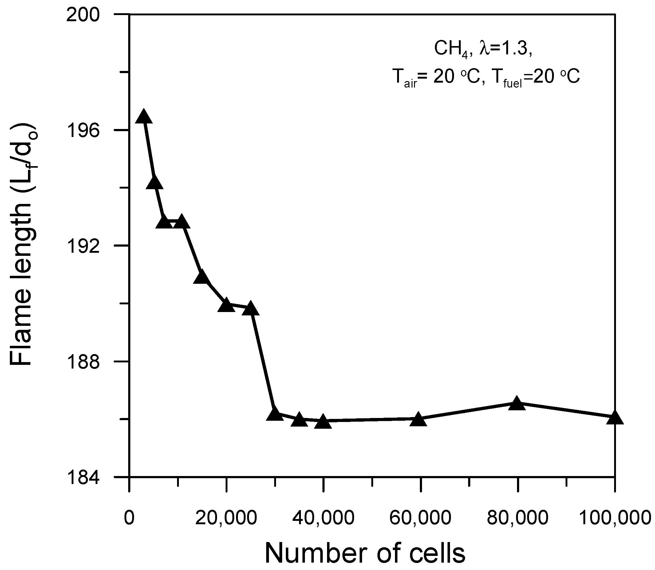
2-D computational domain geometry and grids with boundary types are illustrated in Figure 2, as presented by Elattar [18]. A hemikiln was used for computational cost saving and an ANSYS package preprocessing tool was used for mesh generation (structured and quadrilateral cells). In the flame region, the grid generated was dense. The boundary conditions of the computational domain were inlet velocities of fuel, primary air and secondary air, pressure of outlet flue gases, and the kiln walls were considered adiabatic. All temperatures and velocities at the kiln inlet were specified as uniform. The grid independence study was carried out using several 2-D meshes with various resolutions. The cells numbers varied from 3 × 10³ to 100 × 103 for illustrating the flame length convergence as depicted in Figure 3. The study shows that cells greater than 30 × 103 had diversity in flame length prediction smaller than 0.2%. Accordingly, the mesh of 30 × 103 cells was used to accomplish the present study.
3. Computational Methodology
3.1. Mathematical Procedure and Assumptions
A CFD approach using ANSYS-Fluent (finite volume technique) was engaged in the current simulation to resolve the Reynolds-Averaged Navier-Stokes equations (RANS) in addition to energy, radiation, and the species transport equations. Steady, incompressible, and axi-symmetry flow were assumed. Moreover, the walls were considered adiabatic (i.e., heat flux = 0) with zero thickness and internal wall emissivity = 1. These assumptions result in relatively approximated and acceptable results if compared with real conditions [19,20]. Kiln rotational speed, bed percent filling, and buoyancy have remarkable impacts on the characteristics and aerodynamics of the flame [21].
Continuity and momentum equations for steady-state flow gas are presented in Equations (1) and (2), respectively, as follows [22]:
where Sm is the source term produced from fuel injection.
The turbulence model (realizable k-ɛ) is distinct from other k-ɛ models in its constant terms, and k and ɛ are transport formulations which are given be Equations (3) and (4).
where Gk and Gb denote turbulence kinetic energy generation of mean velocity gradients and buoyancy. While σk and σɛ are turbulent Prandtl numbers of k and ɛ, C1ɛ and C2 are constants. For the current simulations, the turbulent intensity at inlet (I) was specified 10% for air and 5% for fuel according to Equation (5) [23]:
The chemical reaction was simulated based on PDF and non-pre-mixed combustion models which are effective computational models because of using fewer formulations for resolving. In addition, the chemical reaction kinetics state is fast and the flow can fulfill close to the state of chemical equilibrium [23]. The PDF is a favored method in the case of turbulent combustion flow because of variation in turbulent mixing properties. The current simulation utilizes the β-PDF model for turbulent non-pre-mixed combustion flow simulation because of its distinct results compared to other PDF models [24]. The β-PDF is stated based on the two parameters—mean scalar quantity and variance. Therefore, for simplicity in solution of the species formulations, the mixture fraction in a β-PDF (f) was calculated based on species mass fraction (Zi) as follows:
where ox and fuel refer to oxidizer and fuel inlets, f equals 1 and 0 for fuel and oxidizer streams, respectively, and it varies from 0 to 1 in the flow domain.
The formulations of and (mean mixture fraction and variance) are given by Equations (7) and (8), respectively.
where , σt = 0.850, Cg = 2.860, and Cd = 2. Thus, the chemical reaction was simplified in one variable (f) which features the mixture fraction modeling. Moreover, species mass fractions, density, and temperature and other thermochemical properties were completely associated with f and the instant scalars depend on f as follows:
where represents instant thermochemical scalar quantities and H is the instant enthalpy. Species and temperature average mass fraction, , can be given by Equation (11) for adiabatic systems and Equation (12) for nonadiabatic systems, where the PDF model is expressed as p (f).
Accordingly, the mean time-averaged fluid density, , is given by Equation (13).
where ; and are , .
For solving the formulation of mean enthalpy, , Equation (14) is used:
For pressure interpolation the PRESTO algorithm was used, while SIMPLE algorithm was engaged for coupling pressure and velocity. Species thermal properties were calculated based on the temperature and at a pressure of 1.013 × 10⁵ Pa (standard atmospheric pressure). For solving the enthalpy, the following energy equation was utilized.
where Sh is the source term including radiation and combustion heat transfer rate.
For calculating kiln-radiation heat flux, the P-1 radiation model was used, which is the simplest model amongst the other P-N radiation models [25,26]. It is appropriate for use at higher optical thickness (κ L), where κ and L are the absorption coefficient and domain length scale, respectively. The κ is determined based on the local concentrations of H2O and CO2, total pressure, and path length according to a Weighted-Sum-of-Gray-Gases model which was used in the current simulation and given by Equation (16),
where the term is utilized in energy equation for radiation heat source.
To describe burner swirl, a swirl number (defined as ratio of angular to axial momentum) was used as given by Beer [27]:
For constant parameters: .
3.2. Model Validation
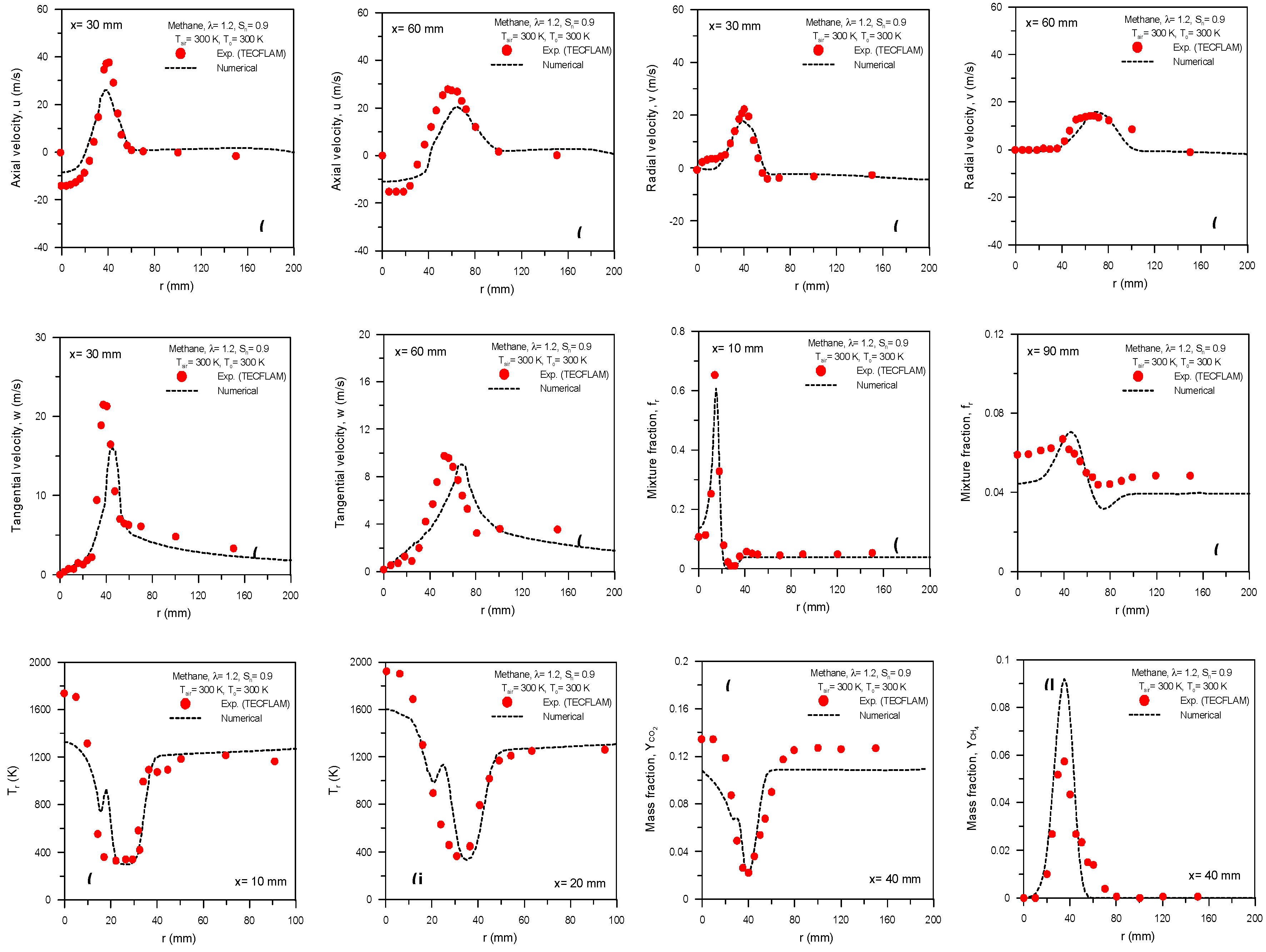
The present model was validated by comparing its results with the experimental results of TECFLAM [19,20]. TECFLAM is a German corporation that presented a series of experimental measurements to provide a database for various flams to improve and validate various numerical model for combustions. Among their work, a database for swirled confined flames generated by natural-gas standard burners is available. The results of the current model are compared with the data in Figure 4. The goals of TECFLAM research programs are to establish a wide experimental database from selective flames and to validate and improve the mathematical combustion models. From this point, the comparisons between experimental measurements of TECFLAM [19,20] and current numerical results are presented in Figure 4.
For the validation work, the model was run based on methane fuel at the conditions—Tair = 300 K, To = 300 K, Sn = 0.9, and λ = 1.2. Figure 4 compares axial, radial, and tangential velocity components of the radial profiles at 30 and 60 mm away from the burner tips. The radial distribution of mixture fraction, mean temperature, CO2 mass fraction, and CH4 mass fraction at different distances from the burner tips are also compared. A reasonable agreement between the results of the current model using (realizable k-ε) the turbulence model and TECFLAM [19,20] experimental data was obtained as shown in Figure 4. The small deviation between the two results can be attributed to the simplifying assumptions used in combustion and turbulence models and to the uncertainty in experimental measurements. Thus, the turbulence model (realizable k-ε) was capable of accomplishing this simulation work.
4. Results and Discussion
4.1. Influence of Primary air Swirl Number (Sn)
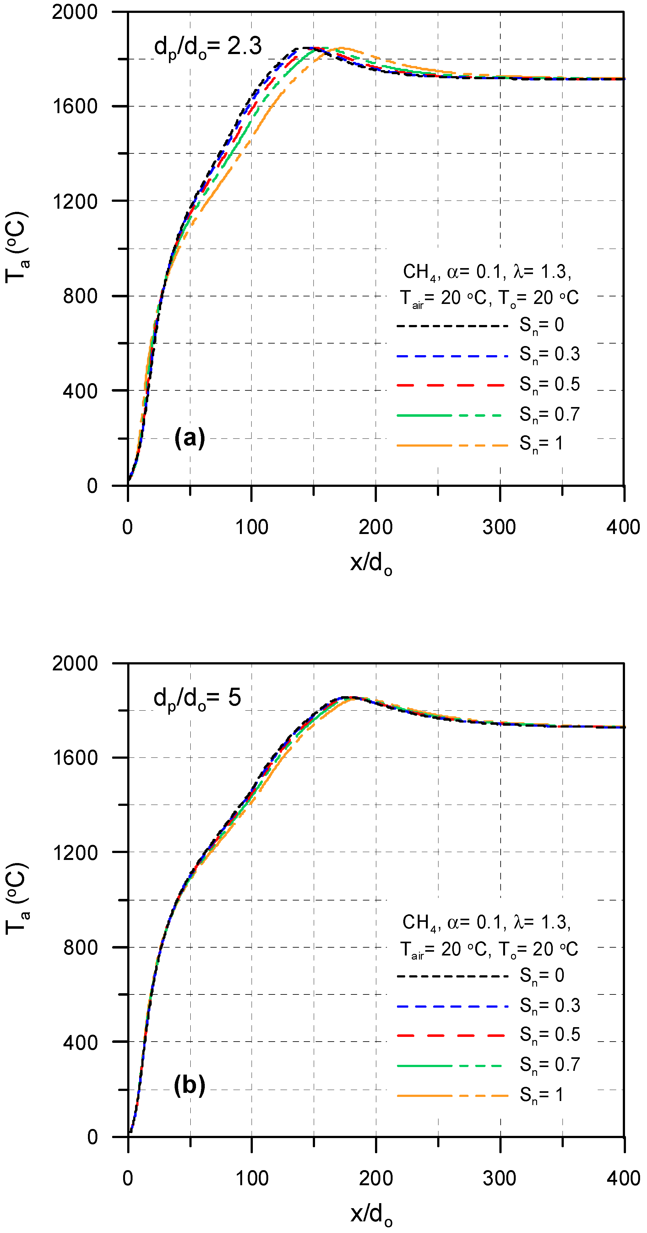
The influences of swirl number (Sn) of the primary air at Tpa = 20 °C, Tsa = 20 °C, To = 20 °C, λ = 1.3, and α = 0.10 on temperature profiles and inverted mixture fraction profiles, velocity vectors, flame length, and mixture fraction contours are shown in Figure 5, Figure 6, Figure 7, Figure 8 and Figure 9 for dp/do = 2.3 and 5.
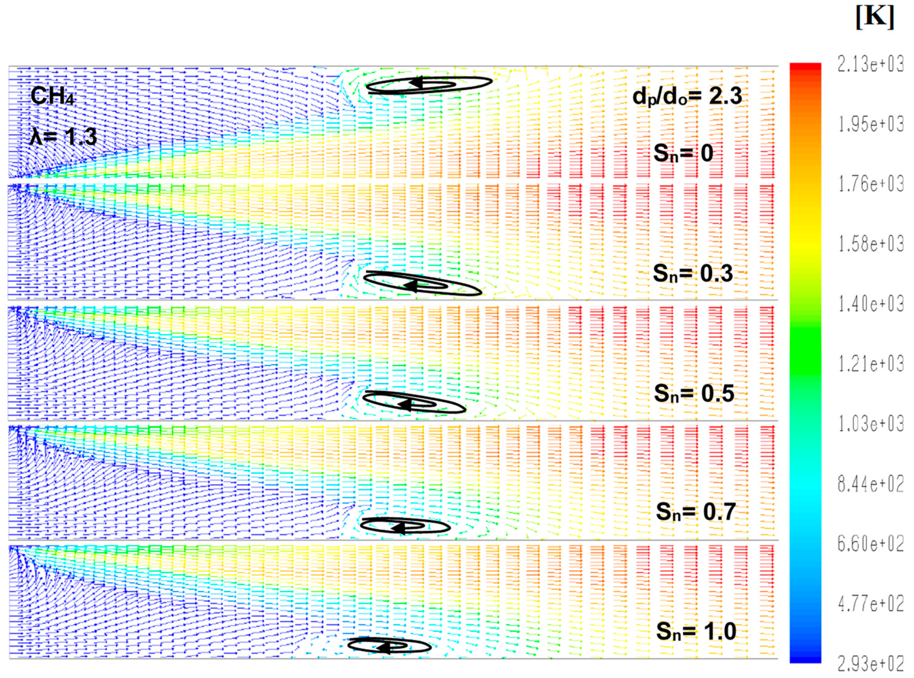
Figure 5a,b illustrates centerline temperature profiles over flame at various swirl numbers (Sn) for two different dimensionless annulus burner diameters of 2.3 and 5. The figures show that the location of the highest flame temperature was moved to right by 20% and 6% with increasing swirl number from 0 to 1 for dp/do = 2.3 and 5, respectively. Moreover, the peak flame temperature magnitudes were unchanged. Furthermore, the impact of swirl number of primary air on the maximum temperature location in the flame vanished with the increase of the annulus diameter for specific excess air and primary air ratio. This is due to the decrease of the size of the recirculation zone and less air diffusion in the fuel with the increase of the swirl number (see Figure 6). The decreased penetration of air into the fuel leads to the increase of the flame length, which causes a shift in highest flame temperature location.
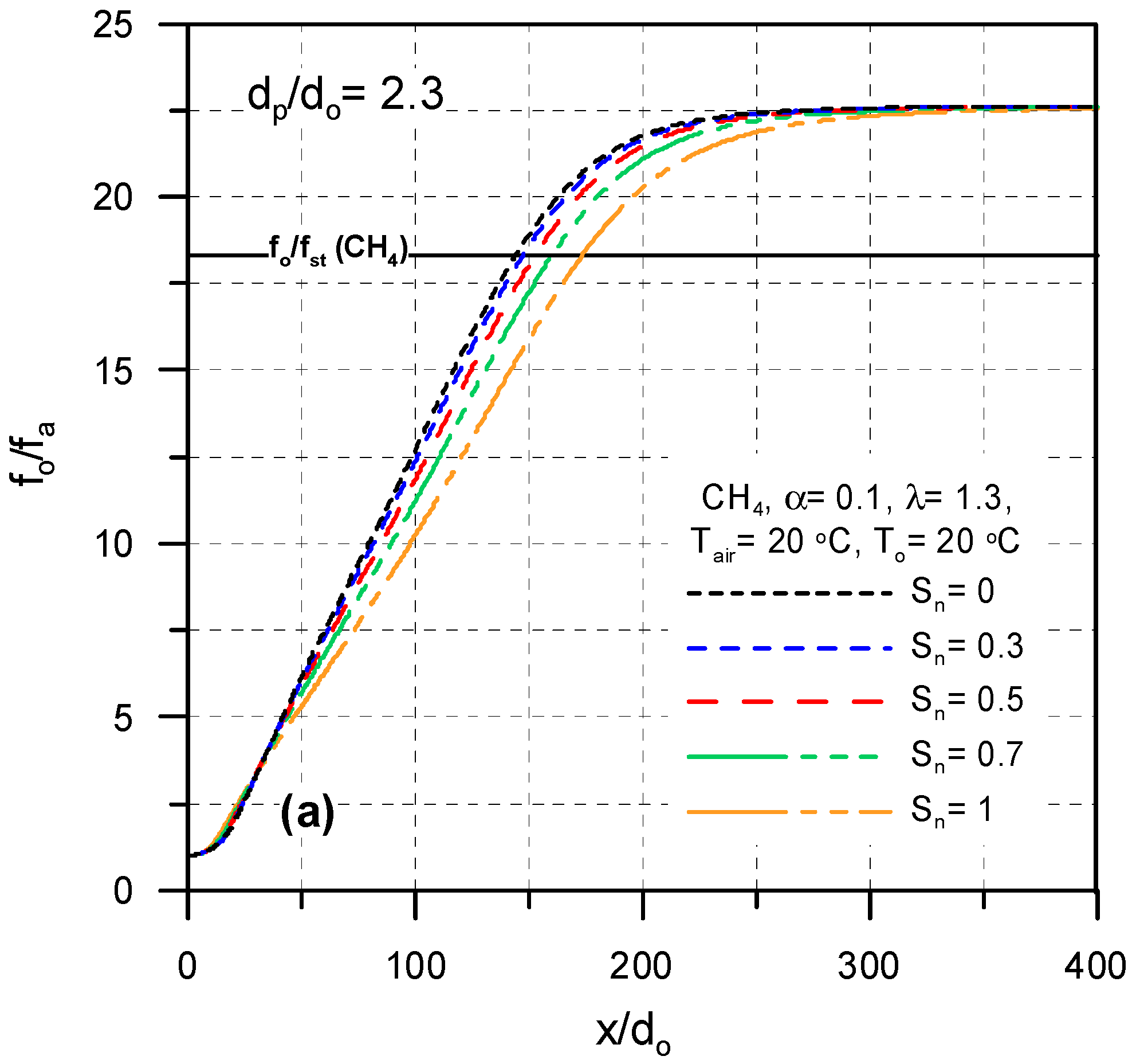
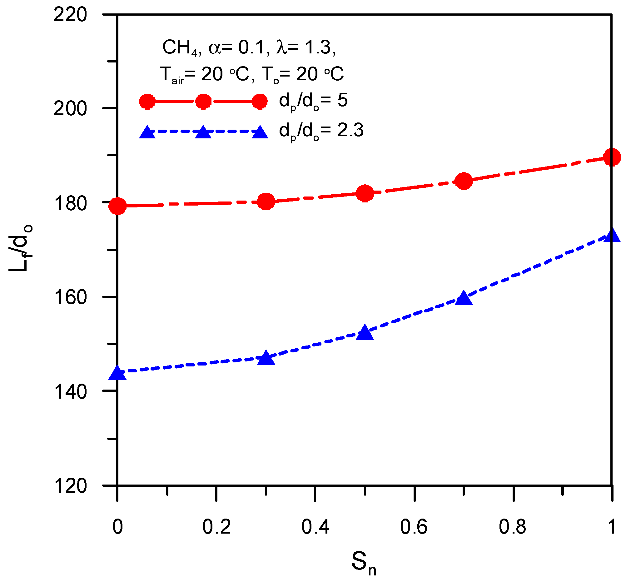
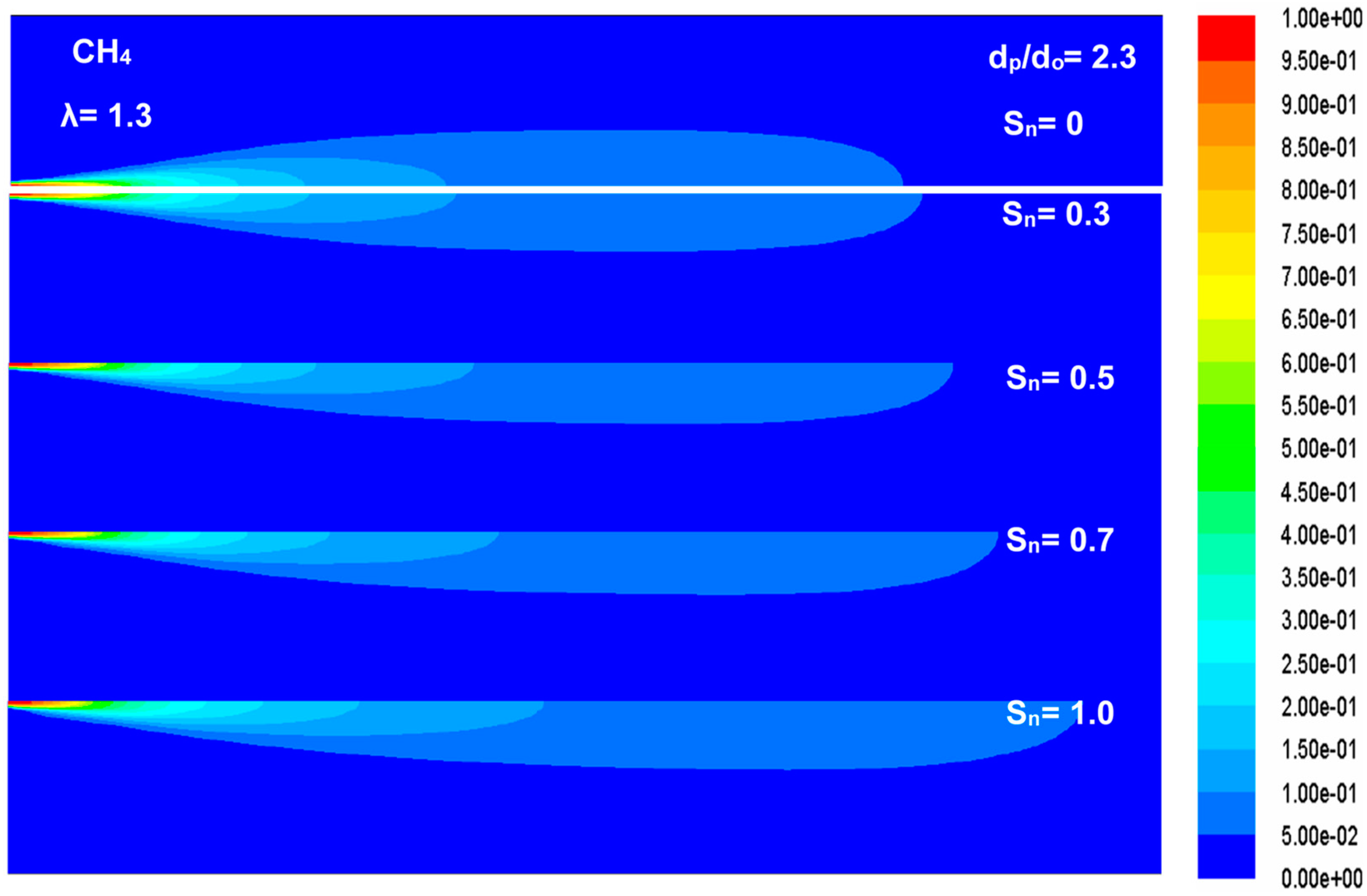
Effect of swirl number of primary air on centerline mixture fraction profiles for two different annulus diameters (dp/do = 2.3 and 5) is explained in Figure 7a,b, respectively. The figure shows that the swirl number of the primary air has a remarkable influence on the profile of the mixture fraction and the flame length. Accordingly, the flame length increases with the increase of the swirl number due to the less diffusion and penetration of air in the fuel, which lead to incomplete reaction in a small distance and the spread of the flame for complete oxidation. The effect of the swirl number of primary air on the flame lengthening is strong at a small annulus diameter and weak at a large annulus diameter. The figures show that the flame lengthens by 20% and 6% with increasing the swirl number of the primary air in the range 0–1 at dp/do = 2.3 and 5, respectively. The predicted flame lengths in the entire range of the swirl number are shown in Figure 8 for annulus diameters dp/do = 2.3 and 5. The figure shows that the swirl number has a remarkable and slight impact on the flame length at dp/do = 2.3 and dp/do = 5, respectively. Figure 9 shows the effect of the swirl number on the mean mixture fraction contours at dp/do = 2.3 for illustrating the influence of Sn on the flame length.
4.2. Influence of Primary air Inlet Annulus Diameter Ratio (dp/do)
Concentric/annulus burners are commonly used in industrial applications with a confined flame for flame stability. The flame characteristics are mainly dependent on the annulus diameter as shown in Figure 10 and Figure 11, which show the effects of the dimensionless annulus diameter on temperature and mixture-fraction profiles, temperature and mixture fraction contours, and velocity vectors.
Figure 10a gives centerline axial temperature profiles for dp/do = 2.3 and 5 and Tpa = 20 °C, Tsa = 20 °C, and Sn = 0.5. The figure shows that the location of the maximum flame temperature point transferred to the right keeping its value with increasing dp/do from 2.3 and 5. This can be attributed to the increase of the velocity of the primary air velocity with the decrease of annulus diameter. The increase of the velocity enhances the mixing process of the fuel and oxidizer leading to a complete reaction in a short distance close to the burner tip. Accordingly, the location of the maximum flame temperature point moved to left with the decrease of annulus diameter leading to a shortening in the flame length (see Figure 10b). Figure 10a,b shows that the location of the maximum flame temperature point moved to the right, i.e., the flame lengthened by 19% due to the increase of dp/do from 2.3 to 5.
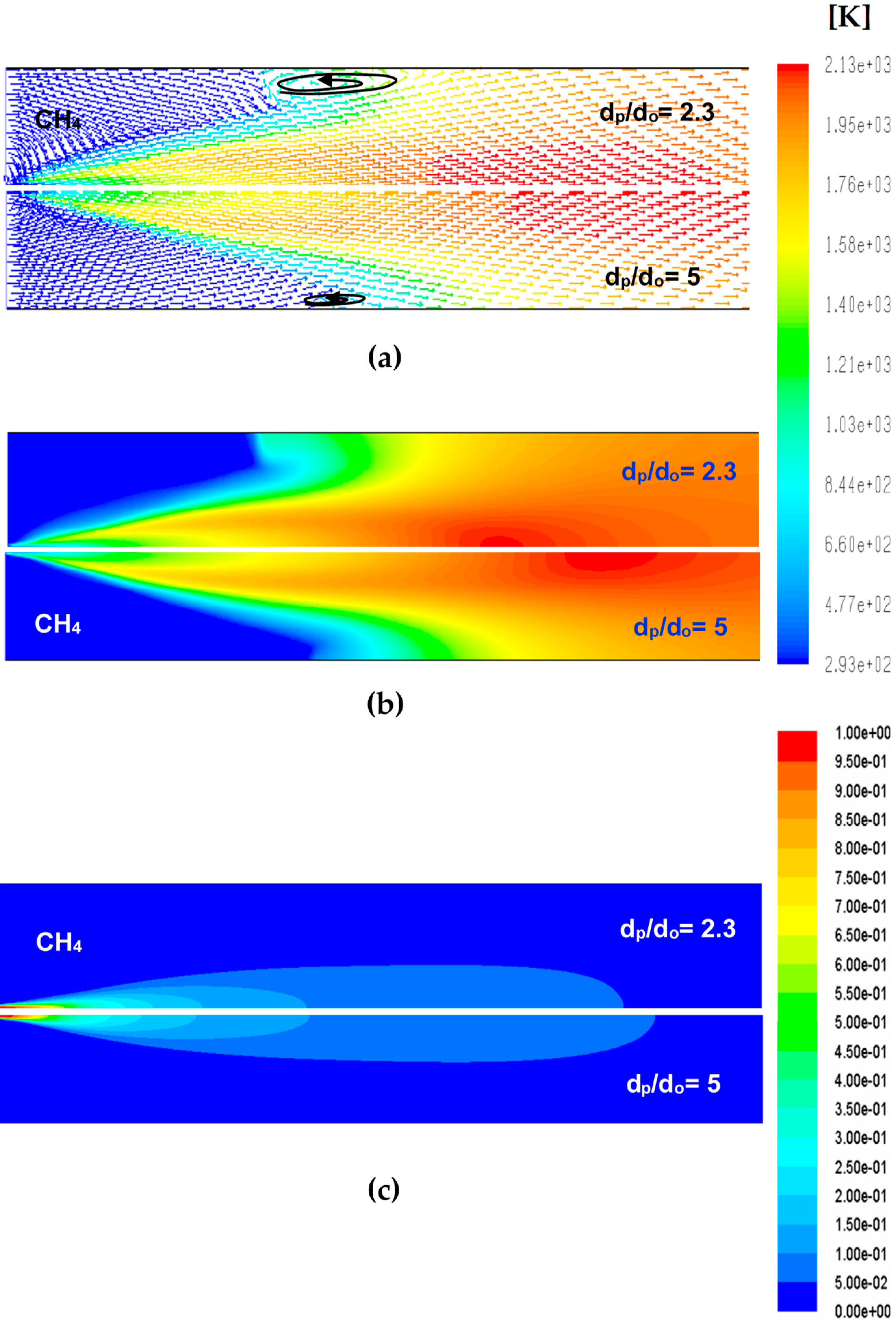
The vectors of the velocity for two annulus diameters, dp/do = 2.3 and 5, are shown in Figure 11a. The figure shows that the recirculation region size decreases with increasing annulus diameter and the location of the maximum flame temperature point moved to the right, causing the increase of the flame length as shown in Figure 11b,c.
4.3. Influence of Temperature of Secondary Air (Tsa)
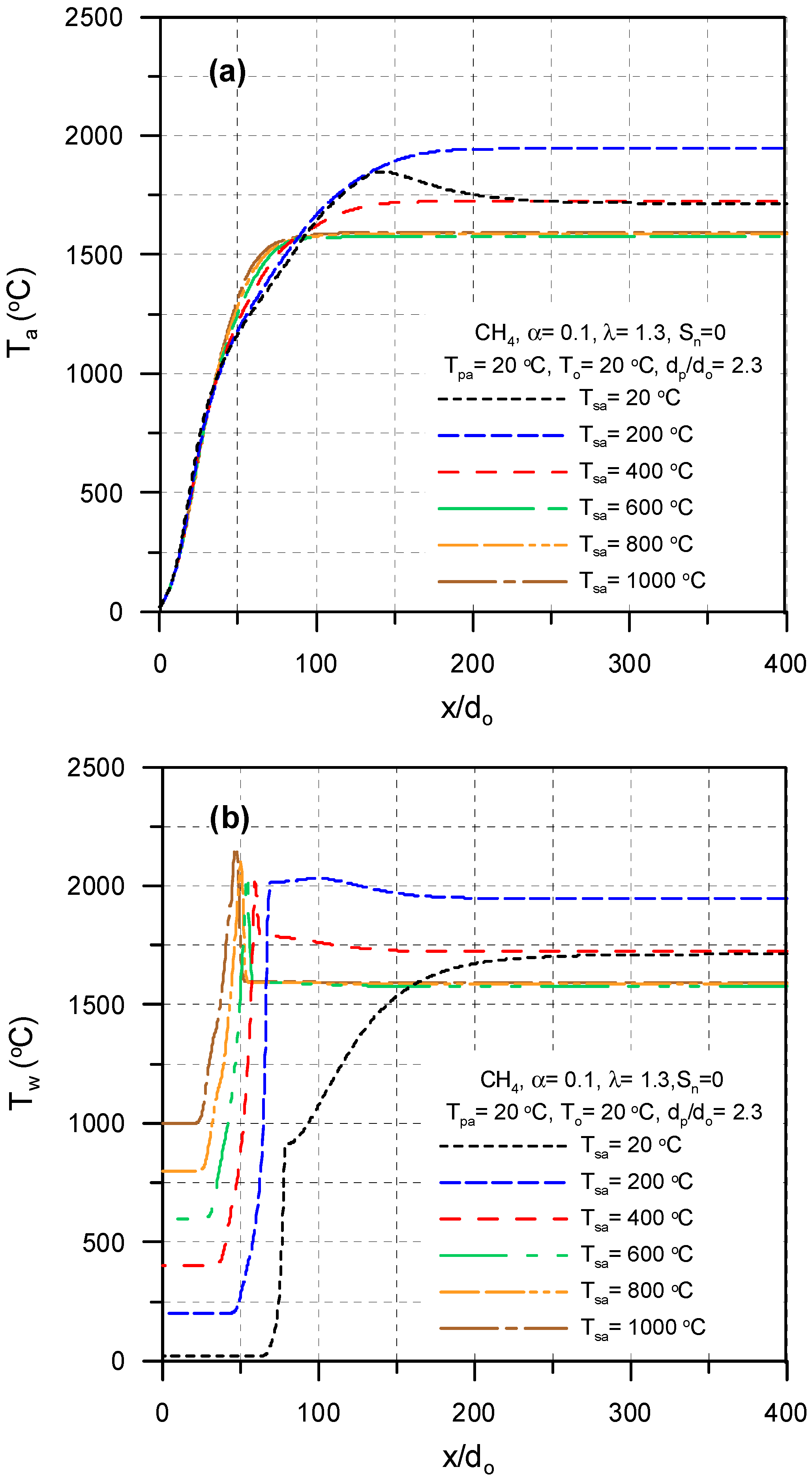
To increase efficiencies of furnaces, heat recovery by preheating the air before combustion is commonly used in the practice of industrial furnaces. The effects of the temperature of the secondary air on air temperature profiles, wall temperature profiles, temperature contours, and velocity vectors are shown in Figure 12 and Figure 13. The variation of the centerline temperature profiles with the temperature of the secondary air in the range 20–1000 °C is illustrated in Figure 12a for dp/do = 2.3, Tpa = 20 °C, To = 20 °C and Sn = 0. The figure shows the increase of the centerline temperature with the increase of the temperature of the secondary from 20 to 200 °C, then the centerline temperature decreases with the increase of the temperature of the secondary air up to 600 °C. Increasing the temperature of the secondary air above 600 °C does not affect the centerline axial temperature profile.
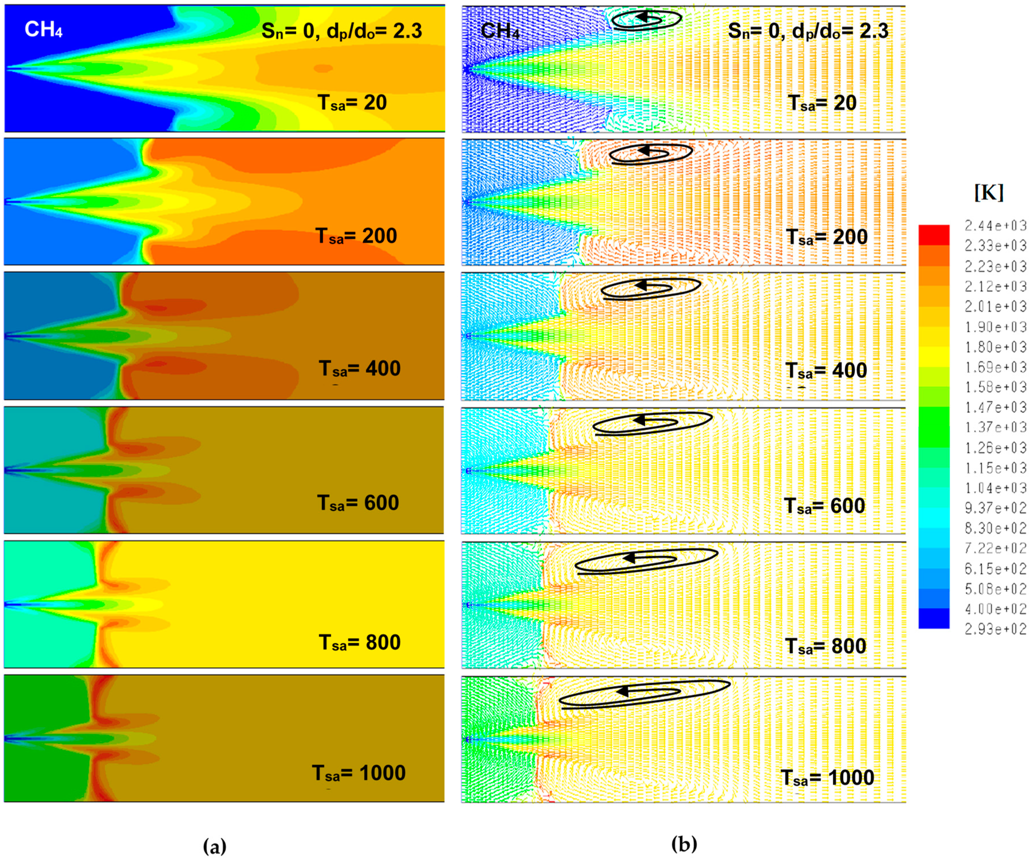
Figure 12b shows the increase of the maximum wall temperature with the increase of the temperature of the secondary air and the shifting of the location of the maximum wall temperature point to the left. This can be attributed to the decrease of the air density with the increase of the temperature of the secondary air, which leads to weak diffusion and mixing of the combustion air with the fuel. This causes the existence of a hot zone close to the air entrance at a high temperature of the secondary air. Figure 13a,b shows the growth of the recirculation region with the increase of the temperature of the secondary air due to the reduction of the momentum of the secondary air causing entrainment and recirculation.
5. Conclusions
Numerical simulation using the CFD method is implemented to predict and discuss the influences of primary air swirl number, primary air inlet annulus diameter, and temperature of secondary air on the length of the rotary kiln flame and its flow field. The main findings obtained from this study are as follows:
- The swirl number of the primary has a remarkable influence on flame length at lower primary air inlet annulus diameter ratio (dp/do = 2.3);
- The flame lengthens with increasing primary air swirl number—the length increases by 20% and 6% with increasing the swirl number from 0 to 1 for dp/do = 2.3 and 5, respectively;
- The flame lengthens with the increase of the annulus diameter of the inlet primary air—the flame lengthens by ~19% with rising of dp/do from 2.3 to 5;
- The peak wall temperature rises and moves close to the burner tip and the recirculation region size growths with the increase of the temperature of the secondary air.
Author Contributions
H.F.E. performed the simulations and drew the figures; E.S. provided the simulation tools and supervision; A.F. and S.R. performed review and wrote computational methodology; A.A.-Z. and S.A.N. wrote and edited the paper. All authors have read and agreed to the published version of the manuscript.
Funding
This research received no external funding.
Conflicts of Interest
The authors declare no conflict of interest.
Nomenclatures
| D | kiln diameter (m) |
| da,i | diameter of secondary air inlet (m) |
| do | fuel-nozzle diameter (m) |
| dp | annulus diameter of primary air inlet (m) |
| f | mean mixture-fraction |
| L | air-fuel ratio, mass basis (kgair/kgfuel) |
| Lf | length of flame (m) |
| R | rotary kiln-radius (m) |
| rp | radius of primary air (m) |
| Sn | swirl number |
| T | local temperature (°C) |
| u | axial velocity (m/s) |
| v | velocity in radial direction (m/s) |
| w | velocity in tangential direction (m/s) |
| x | longitudinal distance measured from burner (m) |
| ε | turbulent dissipation rate (m2/s3) |
| λ | excess-air factor |
| ϕ | equivalence ratio, Φ = (A/F)st/(A/F)actual. |
| ρ | density (kg/m3) |
| Subscript | |
| a | axial |
| air | air |
| o | fuel |
| pa | primary air |
| sa | secondary air |
| st | stoichiometric |
References
- Boateng, A.A. Rotary Kilns Transport Phenomena and Transport Processes; Elsevier Inc.: Oxford, UK, 2008. [Google Scholar]
- Georgallis, M. Mathematical Modeling of Lime Kilns. Ph.D. Thesis, The University of British Columbia, Vancouver, BC, USA, 2004. [Google Scholar]
- Peray, K.E. The Rotary Cement Kiln; Chemical Publishing Co.: New York, NY, USA, 1972. [Google Scholar]
- Manitius, A.; Kureyuz, E.; Kawecki, W. Mathematical Model of the Aluminum Oxide Rotary Kiln. Ind. Eng. Chem. Process Des. Dev. 1974, 13, 132–142. [Google Scholar] [CrossRef]
- Bui, R.T.; Simard, G.; Charette, A.; Kocaefe, Y.; Perron, J. Mathematical Modeling of the Rotary Coke Calcining Kiln. Can. J. Chem. Eng. 1995, 73, 534–545. [Google Scholar] [CrossRef]
- Rovaglio, M.; Manca, D.; Biardi, G. Dynamic Modeling of Waste Incineration Plants with Rotary Kilns: Comparisons between Experimental and Simulation Data. Chem. Eng. Sci. 1998, 53, 2727–2742. [Google Scholar] [CrossRef]
- Kolev, D.; Stefanov, B.; Borisov, D.; Choshnova, D. Method for numerical simulation and graphical presentation of the rate field in a physical model of flash smelting furnaces. J. UCTM 2003, 38, 1147–1154. [Google Scholar]
- Elattar, H.F.; Stanev, R.; Specht, E.; Fouda, A. CFD simulation of confined non-premixed jet flames in rotary kilns for gaseous fuels. Comput. Fluids 2014, 102, 62–73. [Google Scholar] [CrossRef]
- Elattar, H.F.; Specht, E.; Fouda, A.; Bin-Mahfouz, A.S. CFD modeling using PDF approach for investigating the flame length in rotary kilns. Heat Mass Transf. 2016, 52, 2635–2648. [Google Scholar] [CrossRef]
- Elattar, H.F.; Specht, E.; Fouda, A.; Bin-Mahfouz, A.S. Study of Parameters Influencing Fluid Flow and Wall Hot Spots in Rotary Kilns using CFD. Can. J. Chem. Eng. 2016, 94, 355–367. [Google Scholar] [CrossRef]
- Nada, S.A.; Fouda, A.; Elattar, H.F. Parametric study of flow field and mixing characteristics of outwardly injected jets into a crossflow in a cylindrical chamber. Int. J. Therm. Sci. 2016, 102, 185–201. [Google Scholar] [CrossRef]
- Khoei, A.R.; Masters, I.; Gethin, D.T. Numerical modelling of the rotary furnace in aluminum recycling processes. J. Mater. Process. Technol. 2003, 139, 567–572. [Google Scholar] [CrossRef]
- Mastorakos, E.; Massias, A.; Tsakiroglou, C.D.; Goussis, D.A.; Burganos, V.N.; Payatakes, A.C. CFD predictions for cement kilns including flame modelling, heat transfer and clinker chemistry. Appl. Math. Model. 1999, 23, 55–76. [Google Scholar] [CrossRef]
- Marias, F. A model of a rotary kiln incinerator including processes occurring within the solid and the gaseous phases. Comput. Chem. Eng. 2003, 27, 813–825. [Google Scholar] [CrossRef]
- Khalil, A.E.; Brooks, J.M.; Gupta, A.K.; Hasan, A.K. Impact of confinement on flowfield of swirl flow burners. Fuel 2016, 184, 1–9. [Google Scholar] [CrossRef] [Green Version]
- Elbaz, A.M.; Roberts, W.L. Investigation of the effects of quarl and initial conditions on swirling non-premixed methane flames: Flow field, temperature, and species distributions. Fuel 2016, 169, 120–134. [Google Scholar] [CrossRef] [Green Version]
- Elbaz, A.M.; Roberts, W.L. Conical quarl swirl stabilized non-premixed flames: Flame and flow field interaction. Energy Procedia 2017, 120, 206–213. [Google Scholar] [CrossRef] [Green Version]
- Elattar, H.F. Flame Simulation in Rotary Kilns Using Computational Fluid Dynamics. Ph.D Thesis, Magdeburg University, Magdeburg, Germany, 2011. [Google Scholar]
- TECFLAM Cooperation. Available online: www.tu-darmstadt.de/fb/mb/ekt/tecflam (accessed on 26 November 2014).
- Repp, S.; Sadiki, A.; Schneider, C.; Hinz, A.; Landenfeld, T.; Janicka, J. Prediction of swirling confined diffusion flame with a Monte Carlo and a presumed-PDF-model. Int. J. Heat Mass Transf. 2002, 45, 1271–1285. [Google Scholar] [CrossRef]
- Moles, P.B.L.F.D.; Watson, D. The aerodynamics of the rotary cement kiln. J. Inst. Fuel 1973, 46, 353–362. [Google Scholar]
- Shih, T.H.; Liou, W.W.; Shabbir, A.; Yang, Z.; Zhu, J. A new k-ɛ eddy viscosity model for high Reynolds number turbulent flows. Comput. Fluids 1995, 24, 227–238. [Google Scholar] [CrossRef]
- ANSYS, Inc. ANSYS FLUENT User’s Guide; Ansys Inc.: Canonsburg, PA, USA, 2011. [Google Scholar]
- Poinsot, T.; Veynante, D. Theoretical and Numerical Combustion; R.T. Edwards, Inc.: Philadelphia, PA, USA, 2001. [Google Scholar]
- Cheng, P. Two-dimensional radiating gas flow by a moment method. AIAA J. 1964, 2, 1662–1664. [Google Scholar] [CrossRef]
- Siegel, R.; Howell, J.R. Thermal Radiation Heat Transfer; Hemisphere Publishing Corporation: Washington, DC, USA, 1992. [Google Scholar]
- Beer, J.M.; Chigier, N.A. Combustion Aerodynamics; Krieger Publishing: Malabar, FL, USA, 1983. [Google Scholar]
Figure 1.
Physical model layout.

Figure 2.
Computational domain: (a) Geometry, (b) grid and boundary types.

Figure 3.
Grid independence study.

Figure 4.
Model validation—comparisons between present numerical and experimental data of TECFLAM [19,20].

Figure 5.
Effect of swirl number of primary air on centerline temperature profiles: (a) dp/do = 2.3 and (b) dp/do = 5.
Figure 5.
Effect of swirl number of primary air on centerline temperature profiles: (a) dp/do = 2.3 and (b) dp/do = 5.

Figure 6.
Effect of swirl number of primary air velocity vectors at Tair = 20 °C, To = 20 °C, uo = 30 m/s, and α = 0.1.
Figure 6.
Effect of swirl number of primary air velocity vectors at Tair = 20 °C, To = 20 °C, uo = 30 m/s, and α = 0.1.

Figure 7.
Centerline mixture fraction profiles for different primary air swirl numbers at uo = 30 m/s: (a) dp/do = 2.3 and (b) dp/do = 5.
Figure 7.
Centerline mixture fraction profiles for different primary air swirl numbers at uo = 30 m/s: (a) dp/do = 2.3 and (b) dp/do = 5.


Figure 8.
Effects of swirl number on flame length at dp/do = 2.3 and 5 and uo = 30 m/s.

Figure 9.
Mixture fraction contours for different primary air swirl numbers at Tair = 20 °C, To = 20 °C, uo = 30 m/s, and α = 0.1.
Figure 9.
Mixture fraction contours for different primary air swirl numbers at Tair = 20 °C, To = 20 °C, uo = 30 m/s, and α = 0.1.

Figure 10.
Effects of annulus diameters on: (a) centerline temperature profiles, (b) centerline mixture fraction profiles at uo = 30 (m/s).
Figure 10.
Effects of annulus diameters on: (a) centerline temperature profiles, (b) centerline mixture fraction profiles at uo = 30 (m/s).

Figure 11.
Effect of annulus diameters on (a) velocity vectors, (b) temperature contours, and (c) mixture fraction contours at Tair = 20 °C, To = 20 °C, uo = 30 m/s, α = 0.1, λ = 1.3, and Sn = 0.5.
Figure 11.
Effect of annulus diameters on (a) velocity vectors, (b) temperature contours, and (c) mixture fraction contours at Tair = 20 °C, To = 20 °C, uo = 30 m/s, α = 0.1, λ = 1.3, and Sn = 0.5.

Figure 12.
Effect of temperature of secondary air temperature on: (a) temperature profiles and (b) mixture fraction profiles at uo = 30 (m/s).
Figure 12.
Effect of temperature of secondary air temperature on: (a) temperature profiles and (b) mixture fraction profiles at uo = 30 (m/s).

Figure 13.
Effect of temperature of secondary air on: (a) temperature contours and (b) velocity vectors at Tpa = 20 °C, To = 20 °C, uo = 30 m/s, α = 0.1, and λ = 1.3.
Figure 13.
Effect of temperature of secondary air on: (a) temperature contours and (b) velocity vectors at Tpa = 20 °C, To = 20 °C, uo = 30 m/s, α = 0.1, and λ = 1.3.

© 2020 by the authors. Licensee MDPI, Basel, Switzerland. This article is an open access article distributed under the terms and conditions of the Creative Commons Attribution (CC BY) license (http://creativecommons.org/licenses/by/4.0/).
Share and Cite
MDPI and ACS Style
Elattar, H.F.; Specht, E.; Fouda, A.; Rubaiee, S.; Al-Zahrani, A.; Nada, S.A. Swirled Jet Flame Simulation and Flow Visualization Inside Rotary Kiln—CFD with PDF Approach. Processes 2020, 8, 159. https://doi.org/10.3390/pr8020159
AMA Style
Elattar HF, Specht E, Fouda A, Rubaiee S, Al-Zahrani A, Nada SA. Swirled Jet Flame Simulation and Flow Visualization Inside Rotary Kiln—CFD with PDF Approach. Processes. 2020; 8(2):159. https://doi.org/10.3390/pr8020159
Chicago/Turabian StyleElattar, Hassan F., Eckehard Specht, Ali Fouda, Saeed Rubaiee, Ahmed Al-Zahrani, and Sameh A. Nada. 2020. "Swirled Jet Flame Simulation and Flow Visualization Inside Rotary Kiln—CFD with PDF Approach" Processes 8, no. 2: 159. https://doi.org/10.3390/pr8020159
Note that from the first issue of 2016, this journal uses article numbers instead of page numbers. See further details here.