1. Introduction
Solar energy contributes greatly to meeting the energy needs of the world’s population, especially in developing countries [
1,
2]. Therefore, the development of new strategies to reduce energy consumption in buildings must continue [
3,
4,
5,
6,
7]. This is especially true in regions with high levels of solar radiation, where solar energy contributes to reducing the energy needs of different types of buildings, including residential houses.
Air conditioning is used to maintain comfort levels within inhabited spaces. For this purpose, electromechanical devices with different technologies that range from a mechanical fan to more complex intelligent systems for monitoring operating conditions are used. Mechanical fans are the most economical option in terms of technology and operation, and the pedestal and ceiling types are more widely used. The operating principle consists of increasing air currents inside a space, favoring perspiration and heat transfer by convection, regulating the thermal sensation of people in areas with high temperatures that are outside the thermal comfort zone.
In buildings, a considerable part of the energy is used to provide thermal comfort to the occupants. Passive cooling techniques, including solar chimneys, can be an alternative to reduce the energy consumption of the building [
8]. Tariq et al. [
9] recommend for hot climates (>35 °C) combined systems, for example, solar chimneys with water-evaporative cooling to keep indoor temperatures around 8 °C lower than outdoor temperatures. Haihua Zhang et al. [
10] summarize the temperature decreases (drop 1.0–5 °C) achieved using a simple solar chimney without combined systems, for the comfort of a single-story building. Recently, the effects of 30 passive control systems on the decrease in the interior temperature for thermal comfort were examined, finding that on average the decrease in the interior temperature can be achieved by 2.2 °C [
11].
On the other hand, CFD (computational fluid dynamics) simulation has been widely used to optimize the geometric parameters in solar chimneys, such as height, diameter, inclination, and the intensity of solar radiation on the mass flow of air and the increase in temperature in the collector. When it comes to the effect of using sand or gravel as an energy storage unit, further research is required [
12,
13,
14].
In Mexico, 45% of inhabited urban dwellings have mechanical fans, and the average use of 41% of the dwellings in rural areas is 5 to 9 h [
15]. Therefore, the use of renewable energies for thermal conditioning of residential houses is an attractive application field.
With the intention of quantifying the integration potential of a solar chimney in the total volume of a house and promoting the incorporation of passive thermal conditioning systems, in the present work, the incorporation of a solar chimney into a typical house of social interest in Guanajuato, Mexico is evaluated with CFD, with the aim of seeking to promote and increase the flow of air in the home to improve the level of comfort using renewable energy sources. The study was carried out considering a null wind speed in the surroundings, with the intention of guaranteeing the autonomy of the house ventilation without the need for an external flow that can be intermittent or obstructed by the surroundings. The simulation was carried out in ANSYS 2019 software.
1.1. Serial Housing Construction
Due to the search for a way to reduce the costs of housing construction, a serial construction process was chosen, where the design and materials for a considerable number of houses are identical. This type of construction does not consider the thermal conditions inside the house among its priorities, and thus, a subsequent economic cost for electromechanical conditioning is generated.
Because of this situation, efforts are being made to better incorporate architecture into the housing environment to obtain esthetic, acoustic, and energy-saving benefits [
16]. Dalbem et al. [
17] studied through simulation with the Energy Plus program an adaptation of social houses for three climatic zones in Brazil under the passive house standard, optimizing the thermal insulation and window types. Kolokotroni et al. [
18] present experimental results of the application of paints with high thermal emissivity and high solar reflection indexes on the ceilings of low-income houses in Jamaica and found an average reduction in internal temperature of 2.3 °C. However, more research is needed, and an alternative solution is to carry out a simulation to test the new air conditioning systems [
19].
1.2. Ventilation
Natural or forced ventilation is essential in hot climates to increase heat transfer from people to circulating air masses, which are normally at lower temperatures. Sacht and Lukiantchuki [
20] used CFD to analyze the impact of different window sizes and wind incidence angles on the natural ventilation of a small room, establishing an optimal incidence angle of 45°. In addition, taking advantage of air currents for natural ventilation, Reyes et al. [
21] evaluated the impact on thermal comfort of a wind tower with various configurations by CFD for northern Mexico. Hosseini et al. [
22] continued to explore this area of work and tested new configurations for the center of Iran. However, Matour et al. [
23] noted that there is a lack of research on the use of wind-driven ventilation as the dominant natural force for heat dispersion. Renewable energies could be a sustainable source in the control of climatic conditions in buildings [
24].
Solar Chimney
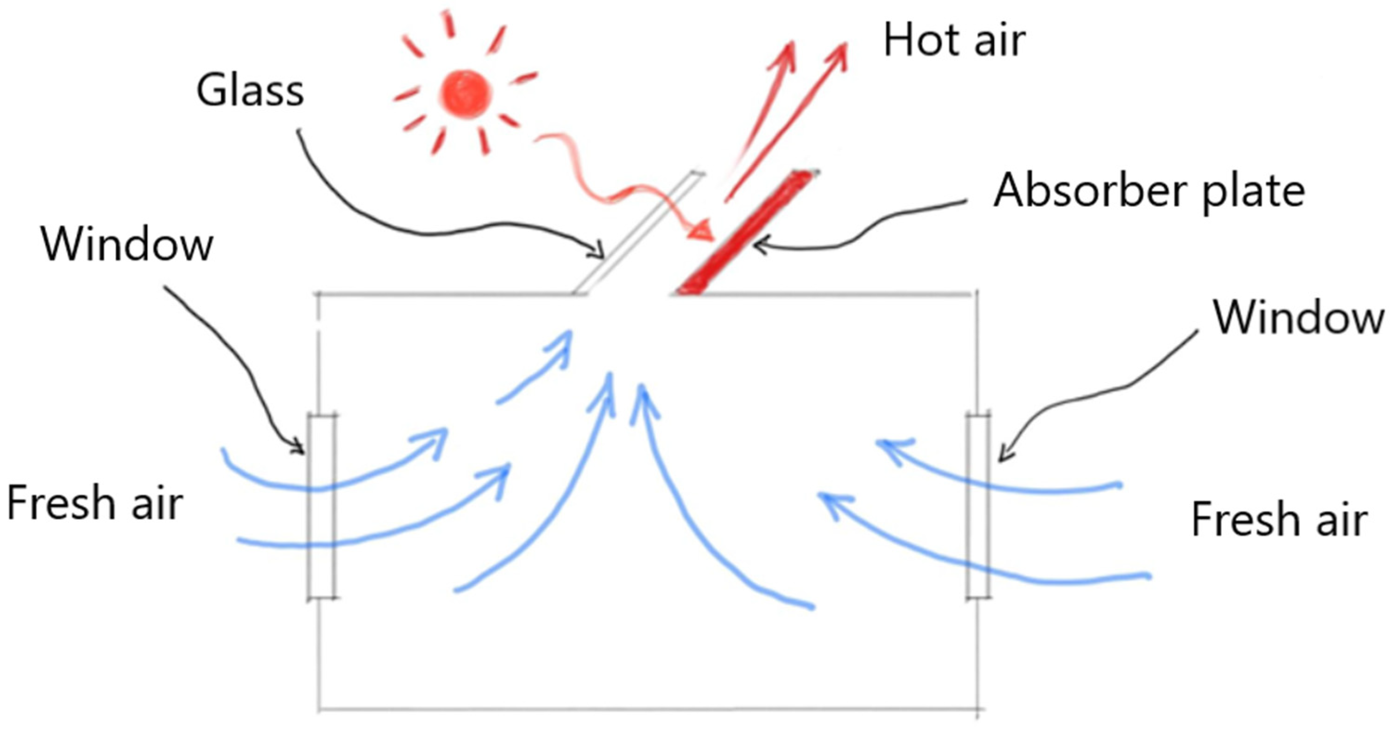
With the intention of promoting natural ventilation in buildings, Zavala-Guillé et al. [
25] numerically analyzed the use of a double-air-channel vertical solar chimney system in three different climates in Mexico on a summer day and found airflow increases of up to 63% compared to a single-channel solar chimney system. The solar chimney consists of a solar collector that heats the air inside; this increase in temperature decreases its density so that it tends to rise, thus sucking air from inside the building to the outside, which in turn draws in outside air through the windows, as shown in the scheme of
Figure 1. A great variety of works demonstrate the performance of natural ventilation and provide theoretical or experimental solar chimney system performance results; however, there are few works on the integration of these systems into the total or partial volume of a housing model [
26,
27,
28,
29,
30,
31].
Few works review the incorporation of technologies, mechanisms, and strategies with a comprehensive vision in housing, such as a wind tower in a classroom by Rabeharivelo et al. [
32], natural ventilation in a building by Yu et al. [
33] and Castillo et al. [
34], and varying the dimensions of a window to provide thermal comfort in an office [
35].
1.3. Computational Fluid Dynamics
To evaluate the state of comfort in the areas of interest, knowledge of temperature gradients, direction, and air speed, among others, is needed. These are integrated into the continuity, momentum, and energy conservation equations used in mathematical models of fluid dynamics [
36].
The analytical solution of the conservation equations is only possible for some general cases and simple geometries. The increase in computational processing capabilities has allowed the development of numerical methods that can provide a solution using the concept of computational fluid dynamics (CFD).
The main distinction between the solution methods lies in the discretization method. Among the finite difference method, finite element method, and finite volume method, the latter is the most-used by most commercial software [
37].
2. Methodology
2.1. Building Characteristics and Simulation Strategy
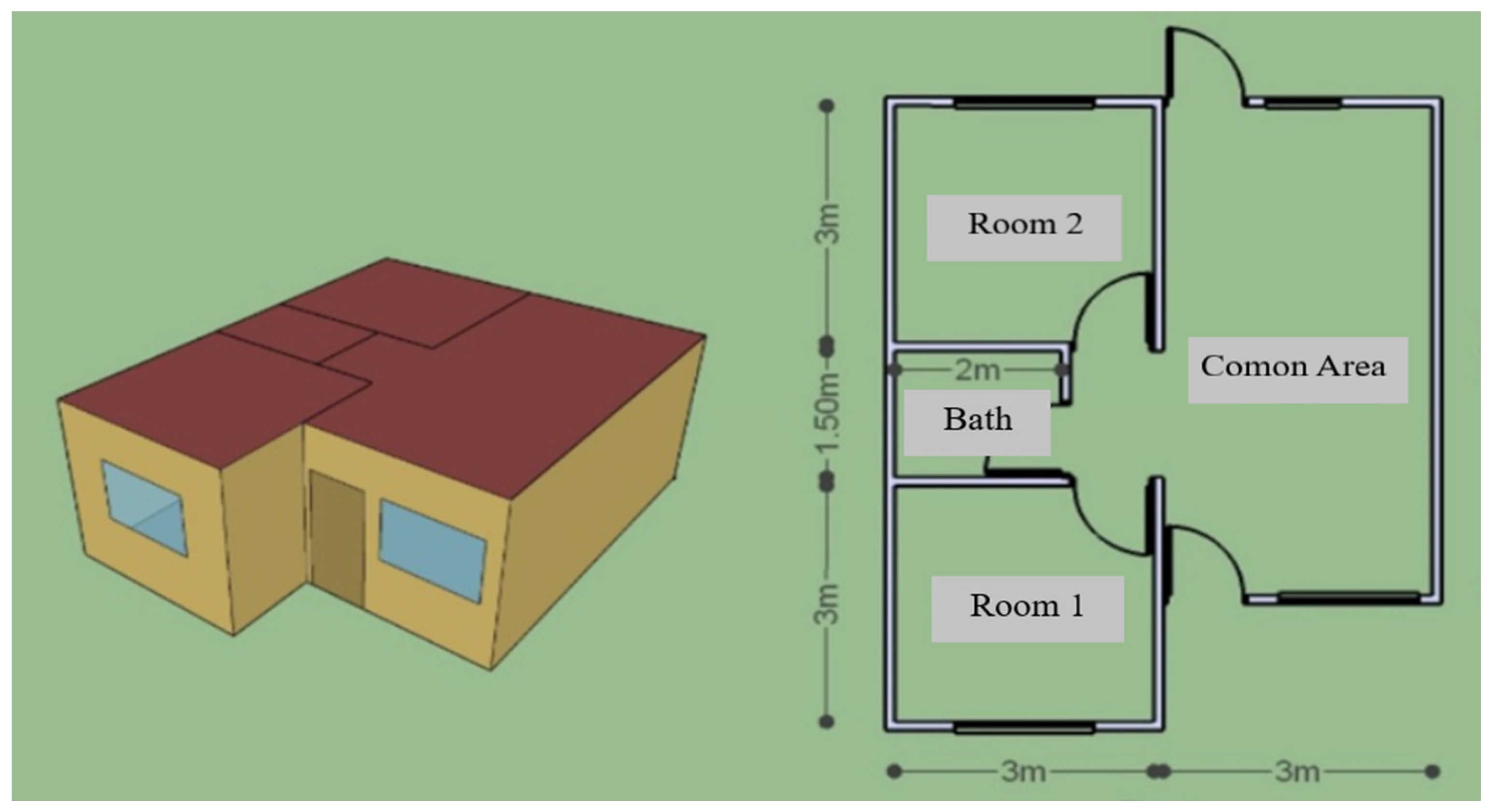
A standard model of a social interest house with two rooms, a bathroom, and common area (kitchen and dining room), with a total area of 39 m
2 and a height of 2.7 m, was selected for the study. The layout of the house is shown in
Figure 2. The area of each window is 1.5 m
2 except for the rear window in the common area, which is 0.8 m
2.
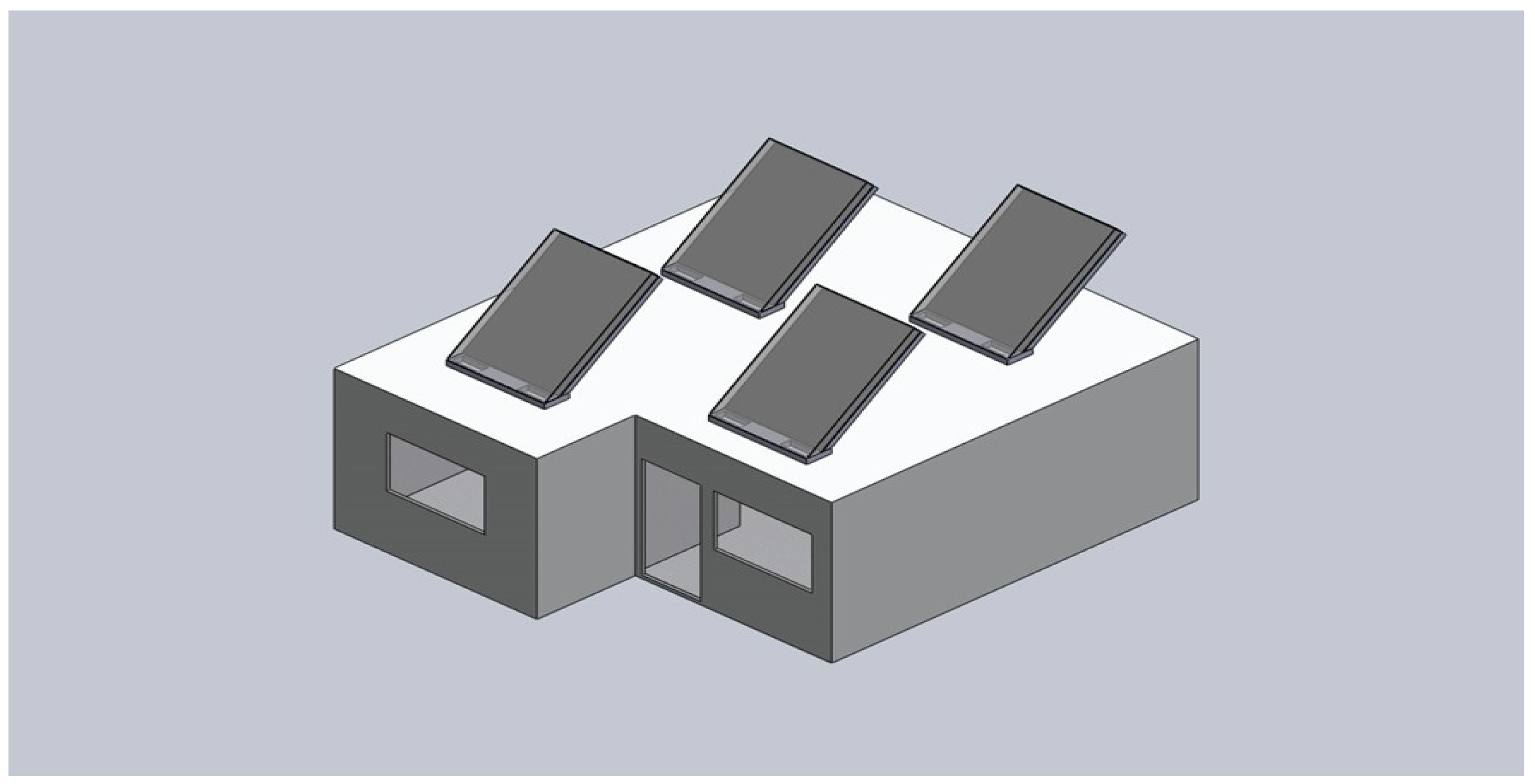
The incorporation of a solar chimney was analyzed with CFD, with the aim to promote and increase the flow of air in the house, as well as to provide a uniform air distribution in the different areas. The study was carried out considering a null wind speed in the surroundings, with the intention of guaranteeing the autonomy of the house ventilation, overcoming the need for an external air flow that can be intermittent or obstructed by the surroundings.
Figure 3 shows a possible arrangement of the solar chimney modules in the house.
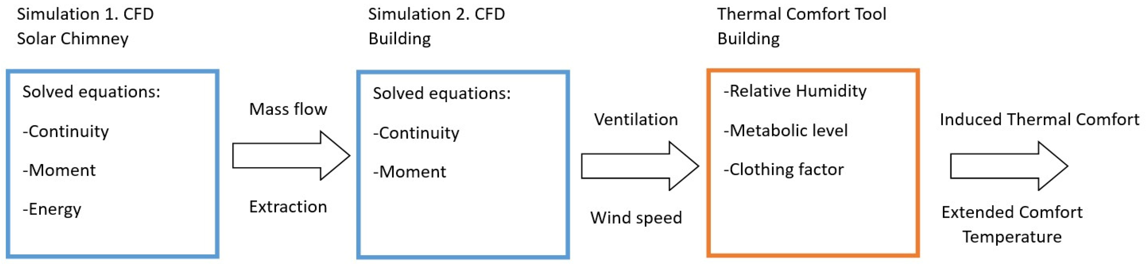
The simulation was carried out in ANSYS 2019 software, which uses the finite volume method to model the thermal behavior of the system. The processing was performed on an HP laptop with 8 GB RAM and a dual-core Intel processor with a speed of 2.3 GHz. The simulation was divided into two parts to reduce the computational demand; a first simulation of the solar chimney was performed, considering the continuity, momentum, and energy conservation equations, and once the results were obtained, the favored mass flow was taken and used as a boundary condition in a second simulation that only considered the interior of the house, solving the equations of continuity and motion. Previously, a validation process was performed for each simulation technique. The American Institute of Aeronautics and Astronautics (AIAA) defines validation as the process to determine if a simulation represents the real world; this implies a comparison with experimental information, and this process must be flexible and allow various levels of precision. It is recommended to divide the system to be validated into different phases with a progressive decrease in complexity so that different characteristics of the computational model can be measured in each phase [
38].
According to the bioclimatic chart of thermal comfort presented by Olgray et al. [
39], which has been taken as a basis with some modifications for various works, thermal comfort is a function of two main parameters, namely relative humidity and temperature, and a space is determined between these two values to define a thermal comfort space. In the case of temperatures greater than those defined in this space, a comfortable wind chill can be achieved through ventilation and moisture management, and the ability to promote thermal comfort in temperatures greater than these ranges was evaluated through induced air flow in the building.
Figure 4 shows the general strategy.
To accurately determine the maximum temperature range where thermal comfort occurs due to induced airflow, the ASHRAE (American Society of Heating, Refrigerating and Air-Conditioning Engineers) 55-2017 PMV method standard was used, which is applicable for buildings with air conditioning systems with a metabolic range of 1 to 1.3 and lower ranges for clothing of 1.5 units of thermal insulation (clo). For the application of this method, the online CBE Thermal Comfort Tool [
40] was used.
2.2. Solar Chimney
2.2.1. Design and Conditions
The climatic conditions of Guanajuato in central Mexico, which is a mostly temperate and dry climate according to the Köppen climate classification, suggest the need for window shades, high thermal inertia with release at night, forced ventilation, internal solar gain, direct passive solar systems with high mass, cooling with dehumidification, and heating with humidification. Rodríguez Miranda et al. [
41] analyzed, through dynamic simulation, the implementation of basic bioclimatic architecture strategies in a house of social interest in Guanajuato, Mexico and projected an annual reduction in energy consumption of 77% for thermal conditioning.
For the summer season in Guanajuato (20°49′–21°14′ latitude and 101°03′–101°27′ longitude), solar radiation at noon falls approximately perpendicular to the normal plane; because this season is the hottest and the intention of this work is to make the most of solar radiation while obstructing the flow of air for the solar chimney as little as possible, an inclination of 45° was taken.
The modules that are distributed on the roof of the house will have a base of 1.5 m, a length of 2 m, and a distance between the plate and glass of 10 cm. The physical properties of the materials are shown in
Table 1.
A solar radiation on the plate of 636 W/m
2 was taken, which corresponds to a normal incidence of 900 W/m
2; for the glass plate, a convection coefficient of 10 W/m
2 Kas taken. A zero gauge pressure was defined at both the air inlet and outlet. To simplify the calculations, the wall in contact with the plate was taken as adiabatic, and finally, an ambient temperature of 20 °C was used, as shown in
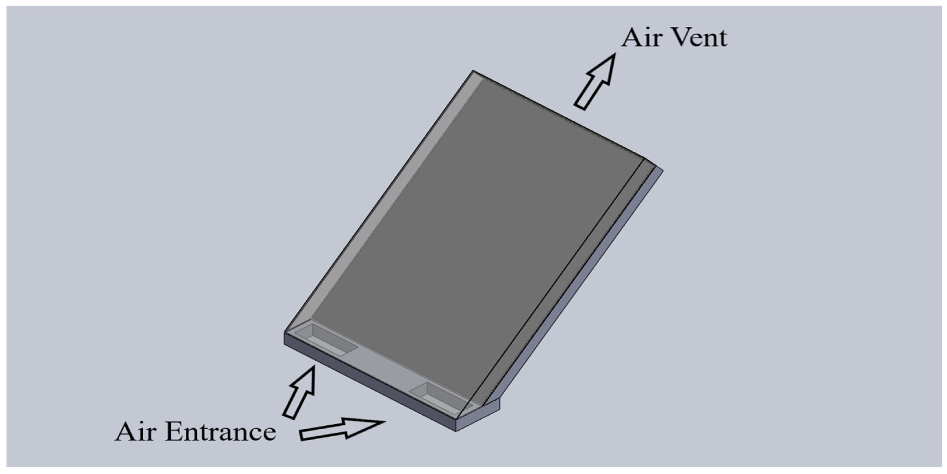
Figure 4. The 3D SolidWorks design and boundary conditions are shown in
Figure 5.
2.2.2. Validation
To give credibility to the simulation, a verification and validation process was performed. The experimental results of Yilmaz and Fraser [
42] were taken and compared with the results of the simulation, and in the experimental data correspond to a parallel plate heated to 373 K, an ambient temperature of 296 K, and zero gauge pressure. To give credibility to the simulation, a verification and validation process was performed. In turn, an independence analysis was performed for mesh sizes of 1 cm, 0.5 cm, and 0.25 cm, with 891,000, 34,680, and 144,000 elements, respectively, with the summary of the results with the 0.5 cm mesh shown in
Table 2.
2.2.3. Simulation
The simulation was performed in 2D, with a mesh size of 0.5 cm, and the equations of motion, continuity, and energy were solved, considering gravity and the fluid modeled as an ideal and turbulent gas using the Reynold’s tensor model with the function of a standard wall [
43].
The solution method was under the pseudotransient coupled scheme with a second-order upwind discretization criterion for all variables except energy and Reynold’s stresses with a first-order upwind discretization.
A residual value of was taken as a convergence criterion for the speed in the three directions, continuity, K, epsilon, uu-stress, vv-stress, ww-stress, and uv-stress, as well as for energy.
The chimney was simulated by incorporating it into a small section of a cavity that would resemble the house to achieve better coupling in the next step with the building in all its details. The total mesh for the geometry was 87,856 elements.
2.3. Incorporation of a Solar Chimney in the Home and Its Validation
Four solar chimney modules were distributed on the roof of the house, as shown in
Figure 3, with the aim of cooling the two rooms and the common area.
To provide credibility to the results to be presented, the simulation methodology was validated and verified by comparing its ability to predict the behavior of turbulent flow in a ventilated cavity reported by Nielsen [
38].
For the mesh independence analysis, a 5 cm mesh was analyzed, giving a total of 489,216 elements; another 10 cm mesh with a wall refinement of 5 cm was analyzed, for a total of 249,648 elements, and a final 10 cm mesh was analyzed for a total of 61,152 elements. The results were compared with the experimental data. These data were measured in a vertical line at 3 m from the origin and a horizontal line at 2.916 m from the floor level, as shown in
Figure 6.
The results of the mesh independence analysis are presented in
Figure 5, and for the refinements of 249,648 and 489,216, the difference is small compared to the difference of elements, so the first was taken for the simulation methodology.
Simulation
The simulation was performed in 3D, and the following two air outlet configurations were tested: a pair of circular channels was placed at the corners in front of the nearest air inlet (windows and doors) and another configuration with a rectangular channel was located in front of the air inlets, as shown in
Figure 7.
The following two arrangements of the four modules were taken: one general arrangement in which two solar chimney modules were used for the common area, one module for room one and another module for room two, ultimately creating a particular arrangement and a second arrangement, in which the four modules were incorporated into each of the previous sections separately.
Table 3 shows the corresponding arrangements.
A gauge pressure equal to zero was established on the air inlet surfaces, and the mass flow value for the air outlets was a function of the solar chimney module values of the preceding simulation.
A general mesh of 10 cm was established, with a refinement of 5 cm in the walls, 0.5 cm in the air outlet, and 1 cm in the windows and walls. The equations of motion and continuity were solved considering gravity, and the fluid was modeled as an ideal and turbulent gas using the K-epsilon model with a standard wall function.
The solution method was under the pseudotransient coupled scheme with a second-order upwind discretization criterion for all variables except energy, K, and epsilon with a first-order upwind discretization.
A residual value of was taken as a convergence criterion for the speed in the three directions, continuity, K, and epsilon.
3. Results and Discussion
3.1. Solar Chimney
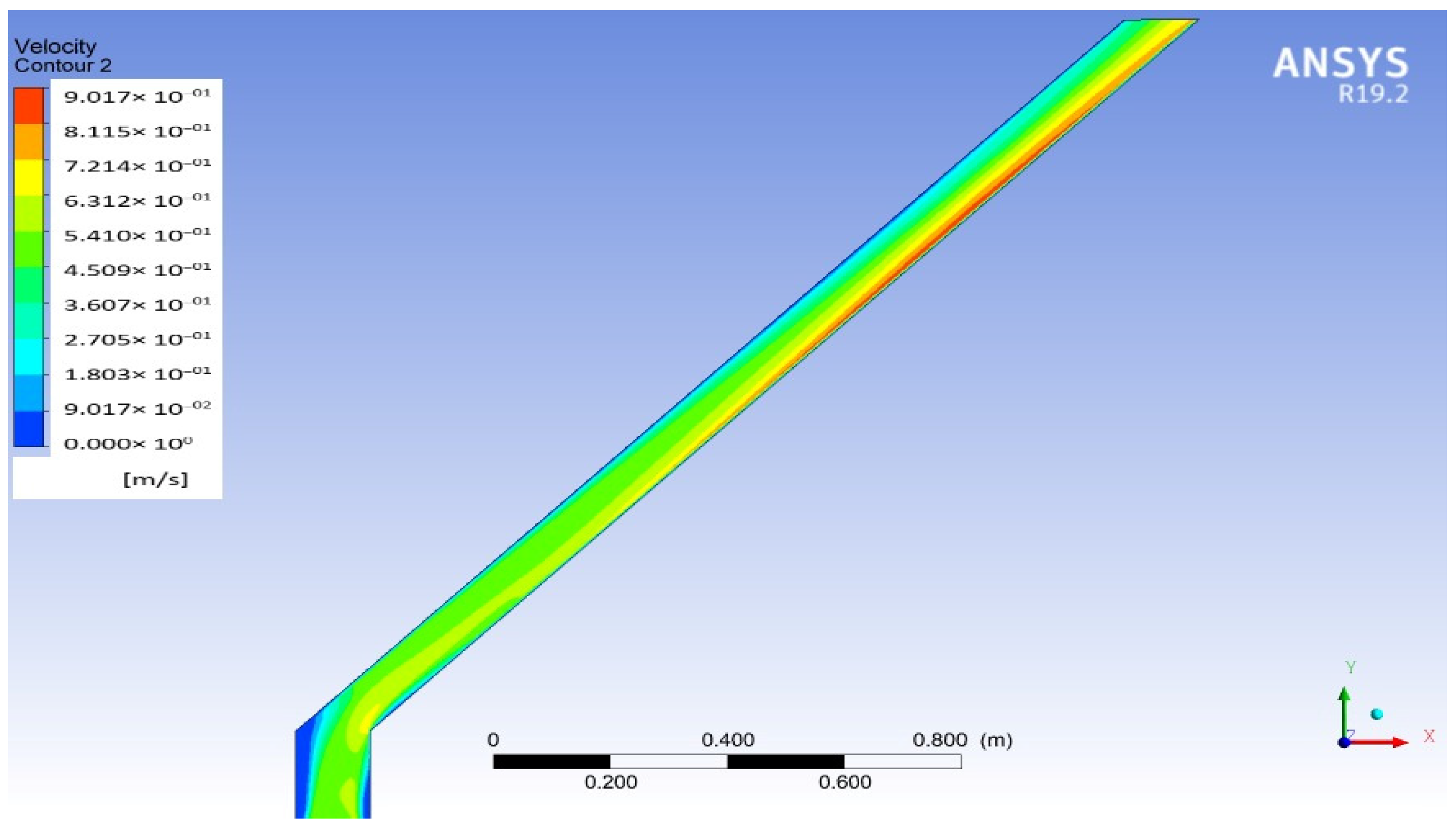
According to the determined conditions, the solar chimney reaches a temperature of up to 127 °C, while the air at the inlet has a temperature of 20 °C. This difference generates a transfer of heat from the plate to the air. The density of the heated air decreases, giving it a buoyancy force in relation to the colder air, generating the velocity profile shown in
Figure 8, and the result is a mass flow of 83.5 g/s per module. Considering a linear variation of the density as a function of the temperature for the temperature ranges handled, the results obtained can be extrapolated to higher or lower ambient temperatures because this would not modify the temperature gradient necessary for a balance between the energy gain and the losses; that is, the mass flow is only a function of the incident radiation, and this induced mass flow will be used to suck external air into the building.
3.2. Incorporation of a Solar Chimney in the House
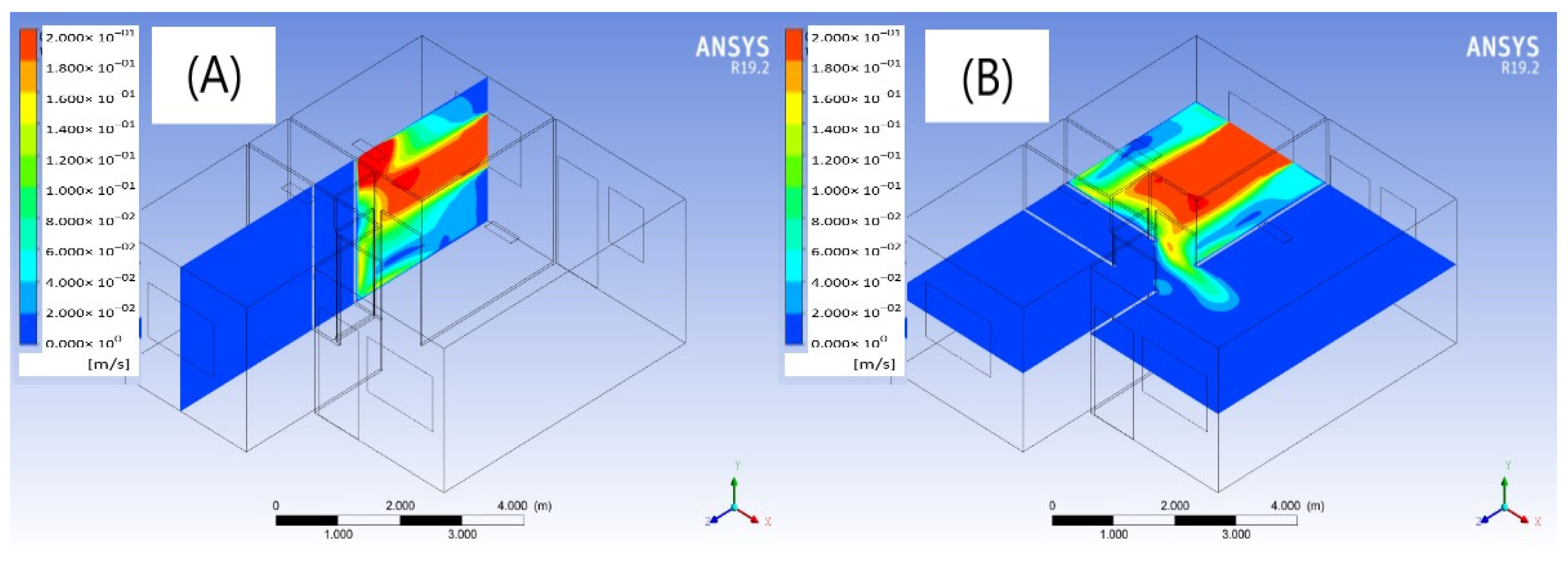
3.2.1. General Arrangement (Rectangular Channel)
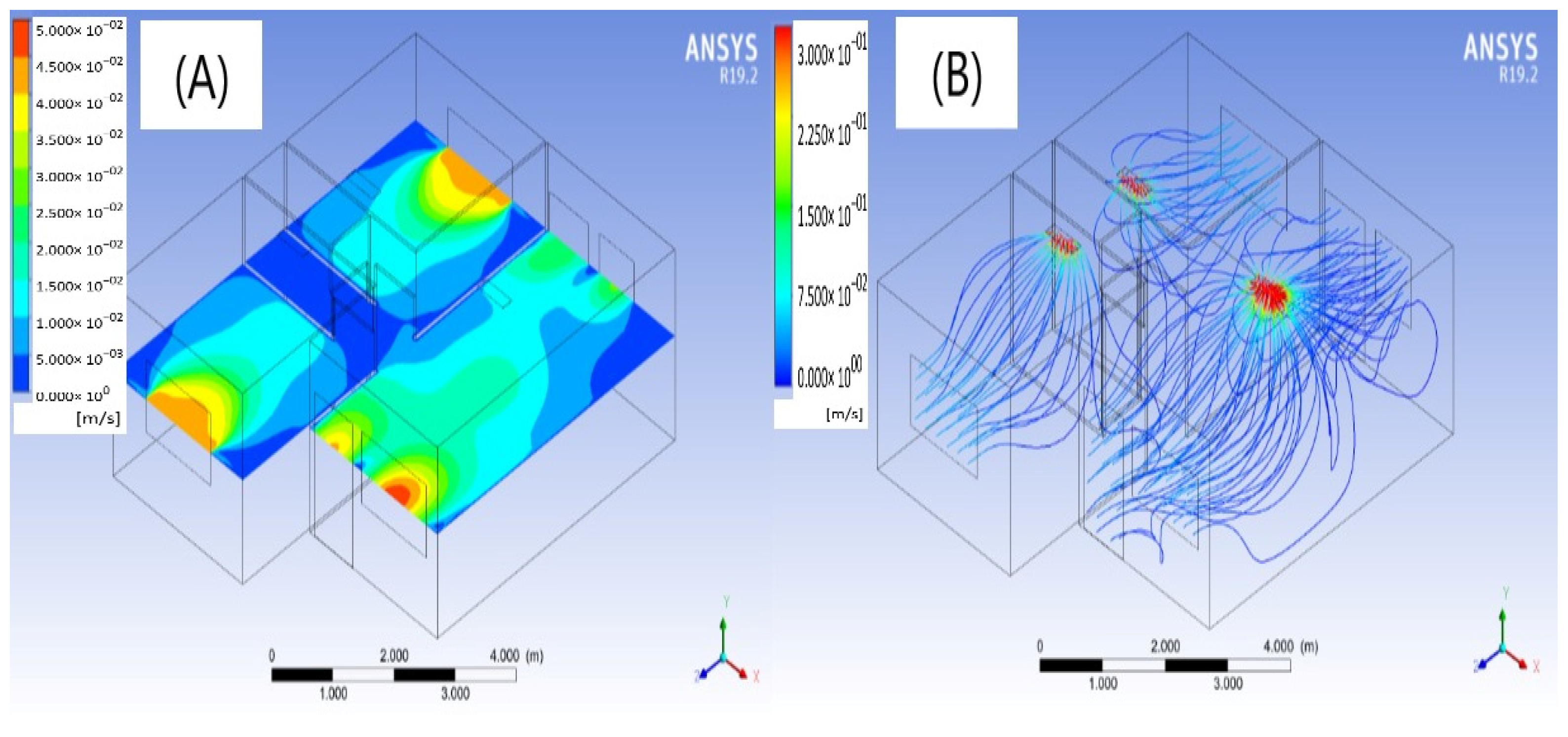
For this configuration, 1,574,584 mesh elements were generated, as shown in
Figure 9, which shows the velocity magnitude in the plane for the general arrangement of the modules (air outlet of 83.5 g/s per room and 167 g/s for the area common), as in the plan for the circular channel. The magnitude is stronger at the entrances, but the change when integrated into the house is gradual, in addition to being concentrated in the central parts of the spaces. This distribution of the air flow can also be observed in the flow lines presented in
Figure 9. The average speed with reference to the plane in the central part of each zone is 0.025 m/s.
3.2.2. Arrangement
As the rectangular arrangement has a more centralized distribution and smoother speed gradients, as well as a higher average speed, the study of this case was continued, considering the four modules involved at the same time per study area, with the intention of producing a higher speed.
Common Area
The incorporation of the solar chimney into the common area was first analyzed, and an increase in mass flow from 167 g/s to 334 g/s was found. Thus, according to
Figure 10, the average speed increased from 0.025 m/s to 0.04 m/s.
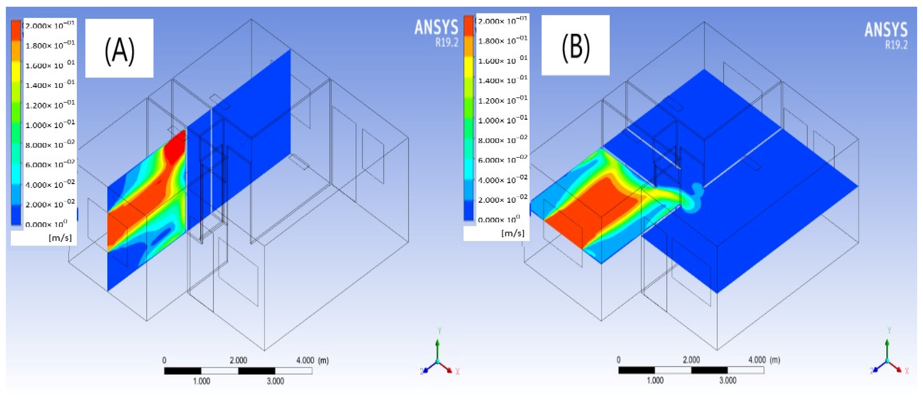
Rooms
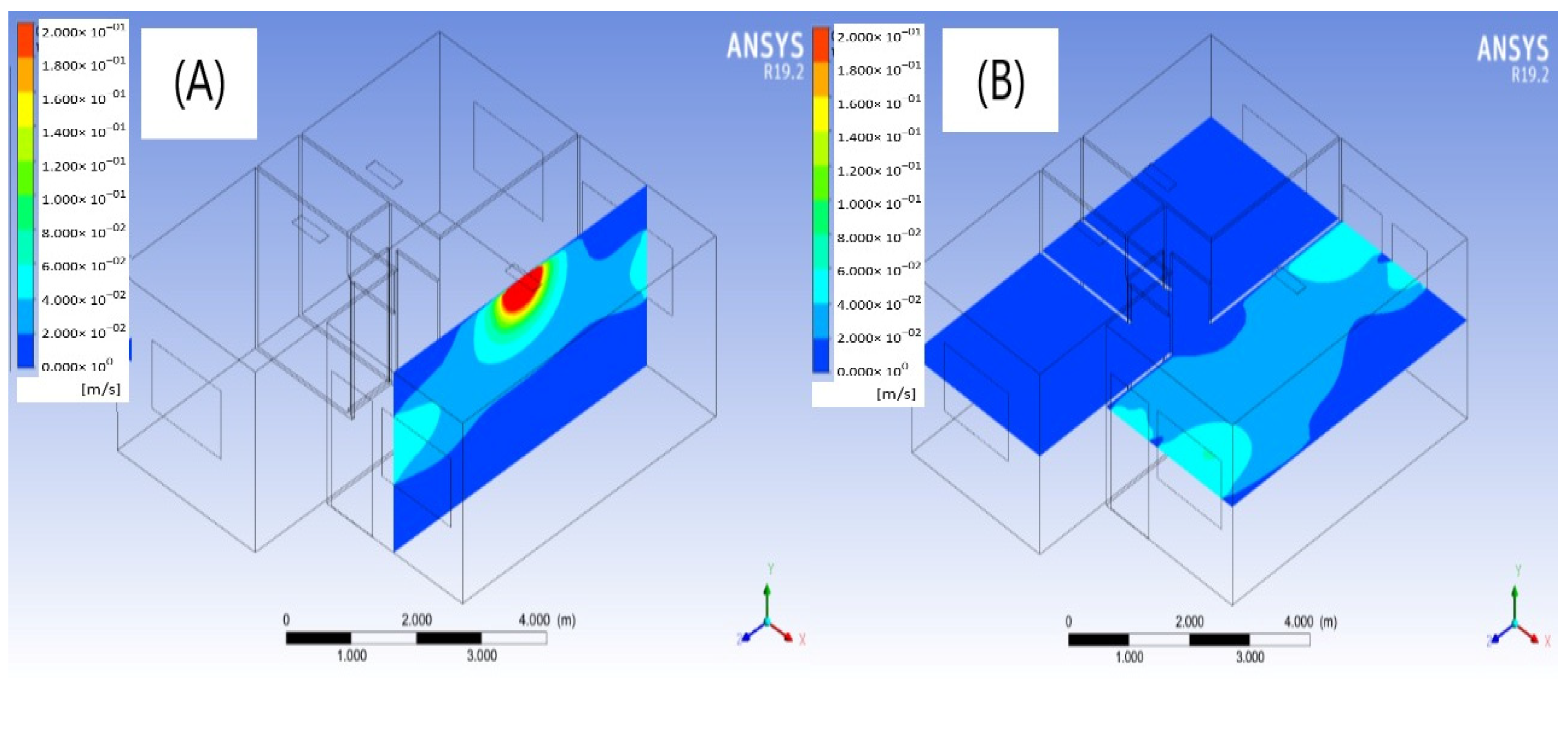
The incorporation of the solar chimney in Room 1 implies an increase in mass flow from 83.5 g/s to 334 g/s. Therefore, the average speed increases from 0.025 m/s to 0.2 m/s according to
Figure 11.
The incorporation of the solar chimney in room 2 implies an increase in mass flow from 83.5 g/s to 334 g/s. It was possible to increase the average speed from 0.025 m/s to 0.2 m/s according to
Figure 12. The speeds are concentrated in the central part, which is the most occupied space, so providing air flow in this area is more important. We observe in
Figure 11 and
Figure 12 that an air flow velocity is obtained in both rooms without counting on an external outside flow (wind speed of 0 m/s), with values similar to those obtained by the measurements of Di Turi et al. [
44] for bioclimatic strategies of natural ventilation considering external flow, and 10% of the speeds reached in the works of Reyes et al. [
21], for the optimization of the internal air flow through a wind tower.
From the point of view of air renewal, important levels are achieved, 38.2 ACH (Air changes per hour) for room 1, 57.4 ACH for room 2, and 19.14 for the common area, comparable to those reported by Z. Zhai at al. [
45] by natural ventilation considering a wind speed of 3 m/s.
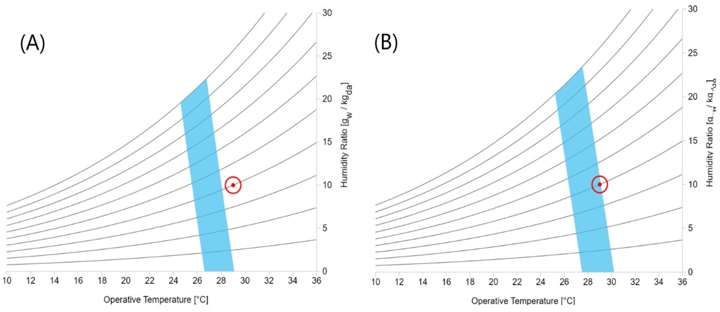
3.3. ASHRAE Standard 55-2017 PMV Method
The velocity magnitude for the general arrangement and the case of the common area is very low, so only the values for the case in the two rooms were evaluated under the standard. A relative humidity of 40%, a metabolic level of 1.0, and a clothing factor of 0.36 clo were taken.
In the case of the two rooms, where there is an average speed in the area of interest of 0.2 m/s each, according to the ASHRAE Standard 55-2017 PMV method, comfortable thermal conditions can be achieved up to an operating temperature of 29 °C.
Figure 13 shows a psychrometric chart, where it is observed how the thermal comfort zone moves to the right for higher temperatures due to the induced air flow.
These results show the viability of achieving thermal comfort, through flexible arrangements of solar chimney modules, concentrating the extraction of air in the area that demands it. The results obtained can be extrapolated to different geographical areas that present temperatures higher than thermal comfort, and in the case of a larger volume in the building, it is possible to choose to increase the number of modules.
4. Conclusions
In the review of the literature, we found different mechanisms and technologies for buildings that seek to improve the thermal conditions in the building by distributing the incident air flow inside the house [
32,
33,
34,
35]. However, no works consider a zero incident flow, a situation that is very common throughout the year. In this work, the incorporation of a solar chimney arrangement in a house of social interest was evaluated by CFD considering the case of zero air flow around it. The implementation of the solar chimney was carried in four modules, where each module generated a mass flow of 83.5 g/s.
Of the two types of configurations tested for the air outlet, higher wind speeds were observed for the rectangular configuration in the central area located in front of the windows, and because this is the area most used by residents, different arrangements were considered.
First, a general arrangement was reviewed, where one module was assigned per room and two modules were assigned to the common area; the highest speeds were obtained in the central part, which is expected to be the area with the greatest circulation or use, in addition to presenting a gradual change of speed when integrated into the house; the maximum speed was 0.025 m/s.
A second arrangement consisted of applying four modules per zone; the speed in the zone with the highest occupancy (the common area) was 0.04 m/s, and that in each room was 0.2 m/s, according to the ASHRAE Standard 55-2017 PMV method. A comfortable zone for the rooms could be achieved up to an operating temperature of 29 °C, emphasizing that a comfortable level could be reached without having any external air flow.
As future work, an analysis of the incorporation of a nonpassive system using different types of solar chimneys considering economic, ecological, technical, operational aspects, etc., with a more robust design for different economic conditions or needs, using different elements or techniques, such as evaporative cooling, will be experimentally tested.
Additionally, it is important to note the importance of CFD as a useful tool for predicting the thermal behavior of a building prior to the construction process, such that it allows a qualitative evaluation of several options in the design process and, thus, the most appropriate selection.
Author Contributions
Conceptualization, S.R.M.; Methodology, R.G.-G., M.A.Z.-A., N.F.-V., G.O.G. and S.R.M.; Writing—original draft preparation, S.R.M., R.G.-G., G.O.G. and M.A.Z.-A.; Writing—review and editing, R.G.-G., M.A.Z.-A. and S.R.M.; Supervision, R.G.-G., S.R.M. and N.F-V. All authors have read and agreed to the published version of the manuscript.
Funding
This research not receive external funds.
Data Availability Statement
The data presented in this study are available on request from the corresponding author.
Conflicts of Interest
The authors declare no conflict of interest.
References
- Arunachala, U.C.; Kundapur, A. Cost-effective solar cookers: A global review. Sol. Energy 2020, 207, 903–916. [Google Scholar] [CrossRef]
- García García, R.; Gamboa, G.O.; Antuñano, M.A.Z.; Ramírez, M.C.; García, S.G.; López, L.V.; Pérez, E.L.O. Sizing photovoltaic systems interconnected to the grid in the industry Maejo. Int. J. Energy Environ. Commun. 2021, 3, 32–37. [Google Scholar] [CrossRef]
- Nutkiewicz, A.; Mastrucci, A.; Rao, N.D.; Jain, R.K. Cool roofs can mitigate cooling energy demand for informal settlement dwellers. Renew. Sustain. Energy Rev. 2022, 159, 112183. [Google Scholar] [CrossRef]
- Pirvaram, A.; Talebzadeh, N.; Leung, S.N.; O’Brien, P.G. Radiative cooling for buildings: A review of techno-enviro-economics and life-cycle assessment methods. Renew. Sustain. Energy Rev. 2022, 162, 112415. [Google Scholar] [CrossRef]
- Rawat, M.; Singh, R.N. A study on the comparative review of cool roof thermal performance in various regions. Energy Built Environ. 2022, 3, 327–347. [Google Scholar] [CrossRef]
- Rawat, M.; Singh, R.N. Impact of light-colored paint materials on discomfort in a building for hot-dry climate. Mater. Today Proc. 2022, 52, 998–1005. [Google Scholar] [CrossRef]
- Wu, Y.; Zhao, H.; Sun, H.; Duan, M.; Lin, B.; Wu, S. A review of the application of radiative sky cooling in buildings: Challenges and optimization. Energy Convers. Manag. 2022, 265, 115768. [Google Scholar] [CrossRef]
- Bhamare, D.K.; Rathod, M.K.; Banerjee, J. Passive cooling techniques for building and their applicability in different climatic zones—The state of art. Energy Build. 2019, 198, 467–490. [Google Scholar] [CrossRef]
- Nguyen, Y.Q.; Wells, J.C. A numerical study on induced flowrate and thermal efficiency of a solar chimney with horizontal absorber surface for ventilation of buildings. J. Build. Eng. 2020, 28, 101050. [Google Scholar] [CrossRef]
- Zhang, H.; Tao, Y.; Shi, L. Solar Chimney Applications in Buildings. Encyclopedia 2021, 1, 409–422. [Google Scholar] [CrossRef]
- Hu, M.; Zhang, K.; Nguyen, Q.; Tasdizen, T. The effects of passive design on indoor thermal comfort and energy savings for residential buildings in hot climates: A systematic review. Urban Clim. 2023, 49, 101466. [Google Scholar] [CrossRef]
- Hassan, A.; Ali, M.; Waqas, A. Numerical investigation on performance of solar chimney power plant by varying collector slope and chimney diverging angle. Energy 2018, 142, 411–425. [Google Scholar] [CrossRef]
- Cuce, E.; Saxena, A.; Cuce, P.M.; Sen, H.; Guo, S.; Sudhakar, K. Performance assessment of solar chimney power plants with the impacts of divergent and convergent chimney geometry. Int. J. Low-Carbon Technol. 2021, 16, 704–714. [Google Scholar] [CrossRef]
- Cuce, E.; Saxena, A.; Cuce, P.M.; Sen, H.; Eroglu, H.; Selvanathan, S.P.; Sudhakar, K.; Hasanuzzaman, M. Performance assessment of solar chimney power plants with natural thermal energy storage materials on ground: CFD analysis with experimental validation. Int. J. Low-Carbon Technol. 2022, 17, 752–759. [Google Scholar] [CrossRef]
- Sener, I. CONUEE Presentación de Resultados México, 2018. Available online: https://www.iea.org/publications/freepublications/publication/statistics_manual_spanish.pdf (accessed on 22 January 2023).
- El Ahmar, S.; Battista, F.; Fioravanti, A. Simulation of the thermal performance of a geometrically complex Double-Skin Facade for hot climates: EnergyPlus vs. OpenFOAM. Build. Simul. 2019, 12, 781–795. [Google Scholar] [CrossRef]
- Dalbem, R.; Grala da Cunha, E.; Vicente, R.; Figueiredo, A.; Oliveira, R.; da Silva, A.C.S.B. Optimisation of a social housing for south of Brazil: From basic performance standard to passive house concept. Energy 2019, 167, 1278–1296. [Google Scholar] [CrossRef]
- Kolokotroni, M.; Shittu, E.; Santos, T.; Ramowski, L.; Mollard, A.; Rowe, K.; Wilson, E.; de Brito Filho, J.P.; Novieto, D. Cool roofs: High tech low cost solution for energy efficiency and thermal comfort in low rise low income houses in high solar radiation countries. Energy Build. 2018, 176, 58–70. [Google Scholar] [CrossRef]
- Kircher, K.J.; Schaefer, W.; Max Zhang, K. A Computationally Efficient, High-Fidelity Testbed for Building Climate Control. ASME J. Eng. Sustain. Build. Cities 2021, 2, 011002. [Google Scholar] [CrossRef]
- Sacht, H.; Lukiantchuki, M.A. Windows Size and the Performance of Natural Ventilation. Procedia Eng. 2017, 196, 972–979. [Google Scholar] [CrossRef]
- Reyes, V.A.; Moya, S.L.; Morales, J.M.; Sierra-Espinosa, F.Z. A study of air flow and heat transfer in building-wind tower passive cooling systems applied to arid and semi-arid regions of Mexico. Energy Build. 2013, 66, 211–221. [Google Scholar] [CrossRef]
- Hosseini, S.H.; Shokry, E.; Ahmadian Hosseini, A.J.; Ahmadi, G.; Calautit, J.K. Evaluation of airflow and thermal comfort in buildings ventilated with wind catchers: Simulation of conditions in Yazd City, Iran. Energy Sustain. Dev. 2016, 35, 7–24. [Google Scholar] [CrossRef]
- Matour, S.; Garcia-Hansen, V.; Omrani, S.; Hassanli, S.; Drogemuller, R. Wind-driven ventilation of Double Skin Facades with vertical openings: Effects of opening configurations. Build. Environ. 2021, 196, 107804. [Google Scholar] [CrossRef]
- Rashid, M.M.; Chowdhury, G.M.; Sultana, T. Comparative Study between Energy Performances of Non-Renewable and Renewable Source Based Grid-Tied HVAC Systems in Subtropical Climates. ASME J. Eng. Sustain. Build. Cities 2022, 3, 034501. [Google Scholar] [CrossRef]
- Zavala-Guillén, I.; Xamán, J.; Álvarez, G.; Arce, J.; Hernández-Pérez, I.; Gijón-Rivera, M. Computational fluid dynamics for modeling the turbulent natural convection in a double air-channel solar chimney system. Int. J. Mod. Phys. 2016, 27, 1650095. [Google Scholar] [CrossRef]
- Bianco, V.; Diana, A.; Manca, O.; Nardini, S. Thermal behavior evaluation of ventilated roof under summer and winter conditions. Int. J. Heat Technol. 2017, 35, S353–S360. [Google Scholar] [CrossRef]
- Bianco, V.; Diana, A.; Manca, O.; Nardini, S. Numerical investigation of an inclined rectangular cavity for ventilated roofs applications. Therm. Sci. Eng. Prog. 2018, 6, 426–435. [Google Scholar] [CrossRef]
- Bunkholt, N.S.; Säwén, T.; Stockhaus, M.; Kvande, T.; Gullbrekken, L.; Wahlgren, P.; Lohne, J. Experimental study of thermal buoyancy in the cavity of ventilated roofs. Buildings 2020, 10, 8. [Google Scholar] [CrossRef]
- Alsailani, M.; Montazeri, H.; Rezaeiha, A. Towards optimal aerodynamic design of wind catchers: Impact of geometrical characteristics. Renew. Energy 2021, 168, 1344–1363. [Google Scholar] [CrossRef]
- Vazquez-Ruiz, A.; Navarro, J.M.A.; Hinojosa, J.F.; Xamán, J.P. Computational fluid dynamics and experimental analysis of the heat transfer in a room with a roof solar chimney. J. Therm. Sci. Eng. Appl. 2022, 14, 041001. [Google Scholar] [CrossRef]
- Li, W.; Subiantoro, A.; McClew, I.; Sharma, R.N. CFD simulation of wind and thermal-induced ventilation flow of a roof cavity. Build. Simul. 2022, 15, 1611–1627. [Google Scholar] [CrossRef]
- Rabeharivelo, R.; Kavraz, M.; Aygün, C. Thermal comfort in classrooms considering a traditional wind tower in Trabzon through simulation. Build. Simul. 2021, 15, 401–418. [Google Scholar] [CrossRef]
- Yu, X.; Zhang, Q.; Kang, J.; Cui, F. Predicting integrated thermal and acoustic performance in naturally ventilated high-rise buildings using CFD and FEM simulation. Build. Simul. 2017, 11, 507–518. [Google Scholar] [CrossRef]
- Castillo, J.A.; Huelsz, G.; van Hooff, T.; Blocken, B. Natural ventilation of an isolated generic building with a windward window and different windexchangers: CFD validation, sensitivity study and performance analysis. Build. Simul. 2019, 12, 475–488. [Google Scholar] [CrossRef]
- Ravikumar, P.; Prakash, D. Analysis of thermal comfort in an office room by varying the dimensions of the windows on adjacent walls using CFD: A case study based on numerical simulation. Build. Simul. 2009, 2, 187–196. [Google Scholar] [CrossRef]
- Zhai, Z. Computational Fluid Dynamics for Built and Natural Environments; Springer: Berlin/Heidelberg, Germany, 2020. [Google Scholar] [CrossRef]
- Versteeg, H.K.; Malalasekera, W. An Introduction to Computational Fluid Dynamics Pearson. 2007. Available online: http://ftp.demec.ufpr.br/disciplinas/TM702/Versteeg_Malalasekera_2ed.pdf (accessed on 3 September 2022).
- AIAA G-077-1998(2002); Guide: Guide for the Verification and Validation of Computational Fluid Dynamics Simulations (AIAA G-077-1998(2002)). AIAA: Reston, VA, USA, 1998. [CrossRef]
- Eduardo Benitez Victor Olgyay—Arquitectura Y CLIMA—AF.pdf. Available online: https://www.academia.edu/33177556/Victor_Olgyay_ARQUITECTURA_Y_CLIMA_AF_pdf (accessed on 2 April 2023).
- Tartarini, F.; Schiavon, S.; Cheung, T.; Hoyt, T. CBE Thermal Comfort Tool: Online tool for thermal comfort calculations and visualizations. SoftwareX 2020, 12, 100563. [Google Scholar] [CrossRef]
- Rodriguez Miranda, S.; Martínez Alvarez, O.; González Nava, C. Evaluación por simulación dinámica del comportamiento térmico en una casa interés social con la incorporación de estrategias de arquitectura bioclimática en Guanajuato, México. Ing. Investig. Y Tecnol. 2021, 22, 1–13. [Google Scholar] [CrossRef]
- Yilmaz, T.; Fraser, S.M. Turbulent natural convection in a vertical parallel-plate channel with asymmetric heating. Int. J. Heat Mass Transf. 2007, 50, 2612–2623. [Google Scholar] [CrossRef]
- Davidson, P.A. Turbulence: An Introduction for Scientists and Engineers; Oxford University Press: Oxford, UK, 2015. [Google Scholar]
- Di Turi, S.; García-Pulido, L.J.; Ruggiero, F.; Stefanizzi, P. Recovery of ancient bioclimatic strategies for energy retrofit in historical buildings: The case of the Infants’ Tower in the Alhambra. Energy Procedia 2017, 133, 300–311. [Google Scholar] [CrossRef]
- Zhai, Z.; Hamilton, S.D.; Huang, J.; Allocca, C.; Kobayashi, N.; Chen, Q. Integration of Indoor and Outdoor Airflow Study for Natural Ventilation Design Using CFD. 2000. Available online: https://www.aivc.org/resource/integration-indoor-and-outdoor-airflow-study-natural-ventilation-design-using-cfd (accessed on 15 March 2023).
| Disclaimer/Publisher’s Note: The statements, opinions and data contained in all publications are solely those of the individual author(s) and contributor(s) and not of MDPI and/or the editor(s). MDPI and/or the editor(s) disclaim responsibility for any injury to people or property resulting from any ideas, methods, instructions or products referred to in the content. |
© 2023 by the authors. Licensee MDPI, Basel, Switzerland. This article is an open access article distributed under the terms and conditions of the Creative Commons Attribution (CC BY) license (https://creativecommons.org/licenses/by/4.0/).


 ,
, 


