
Feasibility Study on Space Reorientation for Liquid Hydrogen Tanks by Means of Evaporated Exhaust Gas

1
School of Energy and Power Engineering, Xi’an Jiaotong University, Xi’an 710049, China
2
Zhangjiagang CIMC Sanctum Cryogenic Equipment Co., Ltd., Zhangjiagang 215634, China
*
Author to whom correspondence should be addressed.
Processes 2023, 11(4), 1278; https://doi.org/10.3390/pr11041278
Submission received: 15 March 2023
/
Revised: 3 April 2023
/
Accepted: 14 April 2023
/
Published: 20 April 2023
(This article belongs to the Special Issue Liquid Hydrogen Production and Application)
Abstract
:A thermal equilibrium model is established to investigate the heat leak of a space liquid hydrogen tank under different thermal adiabatic structures. The feasibility of the common bulkhead tank in realizing thrust or rotation reorientation by evaporated exhaust gas has been systematically studied. The results indicate that the space radiation heat leak is the primary heat leak in spray-on foam insulation (SOFI) adiabatic tanks. However, the common bulkhead heat leak is dominant in the tank with multilayer insulation (MLI) or self-evaporation vapor cooled shield (VCS). For the continuous stable adiabatic exhaust, the tank with SOFI (over 114 W/m2) could realize reorientation with the acceleration of over 5.5 × 10⁻⁴ m/s2 generated by the exhaust. Meanwhile, the tank that adopted MLI or VCS (below 18 W/m2) struggled to achieve gas–liquid separation with the acceleration below 8.7 × 10⁻⁵ m/s2 generated by exhausting. The rotational angular velocity of the tank through exhausting increases with the fill level dropping and exhaust pressure rising. Reorientation by a TVS intermittent exhaust may be possible in some cases, with sufficient exhaust time. This study provides a theoretical basis for reorientation using the exhaust gas of liquid hydrogen.
1. Introduction
Cryogenic propellants such as liquid hydrogen and oxygen have become the preferred space launch propellants for future deep space exploration due to their excellent performance [1]. In the process of on-orbit mission execution, the last stage of a cryogenic rocket will be affected by complex external heat flux, resulting in the evaporation of the cryogenic liquid and causing excess pressure in the tank. To accomplish the long-term on-orbit storage of cryogenic propellants, it is necessary to take thermal protection and pressure control measures.
The insulation methods of cryogenic vessels mainly include ordinary stacking insulation, high vacuum insulation, vacuum powder insulation, and high vacuum multilayer insulation [2]. Spray-on foam insulation (SOFI), as a special kind of stacking insulation, is widely used in the insulation of cryogenic vessels during in-ground parking and launch ascent. Wesley [3] tested several multilayer insulation (MLI) specimens to find the optimal layer density at the Kennedy Space Centre, NASA. The results show that low-density MLI is better for mass and heat load optimization. Apart from optimizing passive insulation methods such as MLI, another way to improve the thermal insulation performance is to recover the hydrogen gas sensible heat, that is, self-evaporation vapor cooled shield (VCS) technology [4]. In addition to the necessary passive thermal protection technology, active insulation technologies such as fluid mixing, refrigeration, and on-orbit exhaust are needed [5]. Among them, the thermodynamic vent system (TVS) developed by NASA integrates these three methods well and is considered to be one of the most feasible means to achieve long-term on-orbit storage of cryogenic propellants [6].
Due to the weak gravity that exists in space, there, surface tension becomes the main force. It leads to gas–liquid mixing and floating, which cannot meet the needs of drainage and exhaust. Therefore, cryogenic fluid management measures are needed to achieve gas and liquid separation. The methods of cryogenic fluid management include forward thrust, slow rotation, and propellant management devices (PMD) [7]. The forward thrust management scheme has good feasibility and reliability; it is widely used in the cryogenic upper stage of large launch vehicles such as the Centaur, and was used in the second stage of the H-2A launch vehicle. In the quest for even greater performance and longer mission duration, Centaur has demonstrated effective propellant control at accelerations in 10−5 g. Similarly, in the 1960s, Saturn demonstrated that effective propellant deposition could be achieved at 2 × 10⁻⁵ g [8]. Rotating reorientation is a fluid management technique similar to forward thrust reorientation. Centrifugal force can separate the liquid and gas, so the liquid is distributed along the wall and less propellant may be used [1]. Rotation propellant control was demonstrated on the DMSP-18 mission (AV-017) in September 2008. This flight demonstrated the effectiveness of liquid rotation, from axial to radial settlement and back to axial settlement at low acceleration [9]. A PMD is a kind of device installed in the tank. It uses surface tension to control liquid propellant. Therefore, the outlet of the tank does not contain gas and can ensure the normal start of the engine. In the HS601 spacecraft model of Hughes Space Communications, the a PMD with plate structure is used as a propellant management device [10].
Propellant management by forward thrust and slow rotation are simple methods that are easy to control. In particular, the technique of forward thrust reorientation by small engines is relatively mature. Researchers have conducted numerous in-depth studies on relevant theories, experiments and numerical simulations. Salzman et al. [11] discovered that the time of complete reorientation of liquid depended largely on geyser dynamics, through quantitative analysis of the liquid accumulation rate. Subsequently, Salzman et al. [12] carried out the drop tower experiment of a scale-model Centaur liquid hydrogen tank. The results indicated that the annular baffle significantly altered the reorientation flow pattern. To activate the reorientation of propellants, Huang et al. [13] compared the continuous reverse gravity acceleration and the impulsive reverse gravity acceleration. It was discovered that the former was more effective in a microgravity environment than the latter. Simultaneously, Huang et al. [14] also researched the forward thrust reorientation combined with rotation. The results show that the reorientation of the fluid can be accomplished more efficiently in a rotating tank than in a non-rotating tank. Li et al. [15,16,17] investigated the reorientation process of different Bond numbers through numerical simulation and a drop tower scale model experiment, and revealed that the thrust with a lower Bond number could save the consumption of the reorientation. Moreover, the initial highly curved interface can significantly reduce the Rayleigh–Taylor instability of the gas–liquid system for liquid reorientation.
In summary, investigators have conducted plenty of research on insulation technology and reorientation technology for cryogenic propellant on-orbit storage. However, previous studies have mainly focused on the reorientation process by small engines. Few documents consider the use of exhausts to achieve propellant reorientation for different adiabatic tanks, which could recover the kinetic energy of the exhaust gas and save fuel consumption compared with the traditional reorientation method using extra small engines. Therefore, the presented work aims to evaluate the feasibility of using exhaust gas to accomplish reorientation in different adiabatic conditions. A thermal equilibrium model of liquid hydrogen tanks is established by analyzing the radiation heat flux and heat conduction of space liquid hydrogen tanks. The heat leak of the tank with different adiabat structures can be obtained. Then, the feasibility of accomplishing forward thrust and rotation reorientation by exhausting is analyzed. The work carried out in this paper could offer an innovative idea and theoretical basis for propellant reorientation, and provide a reference for the long-term storage and application of cryogenic propellants in orbit.
2. Theoretical Analysis
2.1. Research Object
The research liquid hydrogen tank is shown in Figure 1. It is a circular cylinder with an ellipsoidal top and inverted ellipsoidal bottom. The tank has a diameter R of 2.5 m and a length L1 of 7.0 m. The long half-axis of the ellipsoid is the same as the radius of the tank, and the short half-axis L2 is 1.25 m.
When the cryogenic tank goes into orbit, it will run in the near-earth circular orbit with an orbit height of 270 km. During the on-orbit period, the cryogenic fuel tank will be affected by the external heat leak, as shown in Figure 1. The external heat leak includes space radiation heat flux Q1, common bulkhead heat conduction Q2 and metal joints heat conduction Q3. Therefore, the total heat leak of the tank is
2.2. Space Thermal Radiation Model
During the orbit, the space radiation heat flux of the tank mainly comes from solar radiation, earth infrared radiation, earth albedo radiation and deep space infrared radiation.
2.2.1. Solar Radiation
From low earth orbit to geosynchronous orbit, sunlight is assumed to be a uniform parallel beam with a solar constant S (S = 1353 W/m2). It is presumed that at each period, the solar radiation that the tank receives acts equally on the exterior surface. The heat that the projected area of the exterior surface receives from the solar radiation in each period is
where Qsolar is the heat of the solar radiation; S is the solar constant; ϕsolar is the solar radiation angle coefficient; and As is the projection area.
2.2.2. Earth Infrared Radiation
We can assume that the intensity of infrared radiation is identical at each position on the earth’s surface, and that the earth is a thermal equilibrium body with uniform radiation. The heat that the projected area of the exterior surface receives from the earth infrared radiation in each period is
where Qinfrared is the heat of the earth ‘s infrared radiation; ϕinfrared is the earth infrared angle coefficient; and ρ is the average albedo.
2.2.3. Earth Albedo Radiation
Assuming that the earth is a diffuse reflector, the reflection of solar radiation obeys Lambert’s law and is uniform everywhere. The reflection spectrum is identical to the sunlight spectrum, and the albedo is expressed by the average albedo ρ, ρ = 0.3 [18]. The heat flux that the projected area of the exterior surface receives from the earth albedo radiation in each period is
where Qalbedo is the heat of the earth albedo radiative, and ϕalbedo is the earth albedo angle coefficient.
For the near-Earth orbit, the earth’s albedo heat flux makes up a small percentage of the overall heat flux from space radiation. Therefore, to simplify the calculation of ϕalbedo, the following approximation is used:
where Φ is the phase angle.
2.2.4. Deep Space Infrared Radiation
Due to the cryogenic temperature of the space deep space background, which is about 4 K, the cryogenic storage tank will radiate cold energy to the space black background. The cooling capacity of this part is determined by Stephen–Boltzmann law:
where ε is the emissivity of the outer wall, 0.7; Qb is the radiation heat of the tank wall facing the external environment; Tout is the outer temperature of the foam; A is the outer surface area of the tank; and σ is the Stephen–Boltzmann constant is 5.67 × 10⁻⁸ W/(m2·K4).
Therefore, the total space radiation heat flux Qrad accepted by the cryogenic liquid hydrogen tank is
where α is the absorption rate of the outer wall of the tank, 0.4 [18].
2.3. Heat Transfer Model within Insulation Structure
To lessen the heat entering the cryogenic storage tank from the outside, the outside layer of the tank will adopt anti-insulation measures. The research object is a sandwich bulkhead tank. Then, the upper bottom and the cylinder adopt a SOFI or MLI adiabatic structure to lessen the space radiation heat flux. The common bulkhead adopts PMI foam to reduce the heat conduction from the oxygen tank. The heat leak analysis of different adiabatic structures was carried out as follows.
2.3.1. Thermal Analysis of Adiabatic Structure of Liquid Hydrogen Tank
Figure 2 shows the three schematics of the adiabatic structure for the LH2 tank: SOFI, SOFI/MLI and MLI/VCS. The heat flux and temperature profile in the three schemes will be quantitatively analyzed in the following sections. The mental wall is made of 2212 aluminum alloy with a thickness of 3 mm. SOFI is applied directly to the LH2 tank surface. A 10-layer MLI blanket placed over SOFI provides thermal protection. The mental wall of the tank that adopted MLI is ignored due to the thermal resistance being much smaller than MLI.
- (1)
- SOFI
The cylinder of the tank is wrapped with 20 mm SOFI, whose thermal conductivity is 0.03 W/(m·K). The tank wall adopts 2212 aluminum alloy with the thickness of 3 mm. The fitted thermal conductivity is as follows [19]:
Considering the aluminum alloy wall and SOFI, the heat conduction of the cylinder section is
where Kwall is the heat transfer coefficient of the sidewall section; l is the length of the cylinder; Tout is the outside temperature of the tank foam; Th is the temperature of the liquid in the tank; λAl is the thermal conductivity of the aluminum alloy; λfoam is the thermal conductivity of SOFI; R is the radius of the tank; r1 is the radius of the aluminum alloy’s outside wall, r1 = R + δ1; r2 is the radius of SOFI’s outside wall, r1 = R + δ1 + δ2; δ1 is the thickness of the mental wall; and δ2 is the thickness of SOFI.
For the forward dome of the tank, the ellipsoid part is equivalent to a sphere with the same surface area. When it comes to the volume of the tank and the mass of the propellant, it is calculated according to the inherent size of the original shape. The heat conduction of the forward dome is
where Kdome is the heat transfer coefficient of the side wall section; Requ is the equivalent radius of the tank ellipsoid; requ1 is the equivalent radius of the aluminum alloy’s outside wall, requ1 = Requ + δ1; and requ2 is the equivalent radius of SOFI’s outside wall, requ2 = Requ + δ1 + δ2.
Therefore, the total heat conductivity of the adiabatic structure of the tank forward dome and the cylinder is
- (2)
- SOFI/MLI
To meet the ground and on-orbit insulation requirements of liquid hydrogen tanks, a SOFI/MLI composite insulation structure is adopted. The thermal conductivity of MLI in space is substantially lower than that of SOFI, which is crucial for thermal insulation. As a result, while determining the thermal conductivity of space liquid hydrogen tank insulation, the thermal resistance of SOFI is disregarded. Additionally, the diameter of the storage tank is quite large, while the thickness of the multilayer insulation structure is super thin. As a result, in the computation, the cylindrical multilayer insulating structure is represented as a flat plate [20]. The layer-by-layer model is utilized in this paper to examine the temperature distribution in MLI. In order to determine the temperature distribution and heat flux within the MLI, the model iteratively evaluates the radiation heat transfer, solid heat conduction, and gas heat conduction [21]. In the on-orbit stage, MLI is in a high vacuum environment, so the gas heat conduction between layers can be neglected. Therefore, in the on-orbit stage, MLI mainly considers the radiation heat transfer between adjacent radiation layers and the solid heat conduction of spacer materials.
The radiation part is mainly the heat transfer between the radiation screens. The heat flux is
where Kr is the radiation heat transfer coefficient; TH and TC are the hot and cold edge temperature; σ is the Boltzmann constant, 5.67 × 10⁻⁸ W/(m2·K4); and εH and εC are the emissivity of the hot boundary and the cold boundary. For the aluminum radiation screen used in this paper, both are 0.04 [21].
Solid heat conduction mainly includes the heat conduction between the spacer and the adjacent radiation screen, and the interior of the spacer. The heat flux is
where Ks is the thermal conductivity of solid; C1 is the empirical constant, for the polyester mesh in this paper, 0.008; f is the degree of looseness of the spacer material, 0.02; λ is the thermal conductivity of the spacer material; DX is the actual thickness of the spacer between the two radiation screens; and T is the surface temperature of the vacuum chamber, which can be taken as the average temperature of the hot side and the cold side [21,22].
Therefore, the total heat conductivity of the MLI adiabatic structure is
where Adome is the surface area of the forward dome of the tank, and Awall is the surface area of the sidewall.
The thermal resistance between two adjacent radiation screens is determined by Equation (20). The temperature distribution of each layer can be obtained by using the thermal resistance of each layer and the cold end temperature in Equation (21).
where Ri is the total thermal resistance between the i − 1 and i layer radiation screens, and qmul is the heat flux in MIL, qmul = qr + qs.
- (3)
- MLI/VCS
To further reduce the heat leak of the tank and recover the exhaust cooling capacity, the insulation structure of MLI/VCS can be employed. Figure 2c shows the heat transfer process in the composite insulation structure of MLI/VCS. The VCS is positioned in the middle of the thickness of MLI, which is the ideal configuration for a single-layer VCS [23]. In Figure 2c, Qtotal is the overall heat leak, which is equivalent to the heat flux from space radiation. QVCS is the heat absorbed by the VCS; Q1 is the final heat leak into the cryogenic tank. According to energy conservation,
The actual cryogenic liquid hydrogen tank is in a complex and changeable environment in space. To facilitate the theoretical analysis of the MLI/VCS composite insulation structure, this paper makes the following assumptions [24]:
- (1)
- VCS and adjacent MLI are in close contact with no gap. Therefore, the thermal resistance between them can be ignored.
- (2)
- Compared to MLI, the thermal resistance of SOFI can be ignored.
- (3)
- The temperature distribution and heat flux have stabilized in the cryogenic liquid hydrogen tank, the VCS, and the MLI.
The heat flux Qtotal from the external environment into the MLI is
where TW is the outer wall temperature of the insulation; R1 is the thermal resistance of external MLI; and TVCS is the qualitative temperature of VCS, which can be expressed by the average temperature of inlet and outlet, that is,
Tin is the inlet temperature of VCS, which is equal to the temperature of evaporated hydrogen; and Tout is the outlet temperature of VCS, namely the exhaust temperature.
The QVCS taken away by VCS is
where mg is the mass flow rate in the VCS, which is the evaporation of liquid hydrogen in the tank; hin is the enthalpy of hydrogen at the inlet of VCS; and hout is the enthalpy of hydrogen at the VCS outlet.
The final heat leak Qtank can be expressed as
where TC is the cold side temperature, which is the wall temperature of the tank aluminum alloy; R2 is the thermal resistance of SOFI; and R3 is the thermal resistance of internal MLI.
2.3.2. Thermal Analysis of the Common Bulkhead
Polymethacrylimide (PMI) foam, with a thermal conductivity of 0.03 W/(m∙K), is used as a common bulkhead material. The heat leak computation is more complex for the common bulkhead portion, since the PMI foam has a variable thickness. As a result, it is simplified to a uniform thickness in calculation. The common bulkhead’s heat conduction is as follows:
where K2 is the heat transfer coefficient of the common bulkhead; requ3 is the equivalent radius of PMI’s wall, requ3 = Requ+ δ1 + δ3; and δ3 is the foam thickness at the common bulkhead of the tank.
2.3.3. Thermal Analysis of Metal Joints Heat Conduction
The common bulkhead and the sidewall are welded by Y joints. As shown in Figure 3, the Y joints are separated from each other by heat insulation gaskets. The metal joints of the liquid hydrogen tank are fork rings at the sharp corner to the bottom of the heat insulation gasket, with a length of 200 mm. Since the thermal conductivity of aluminum alloy is much larger than that of PMI foam, the radial temperature at the metal joints is not very different. The thermal connection of the tank is simplified to a cylinder with a thickness of 3 mm and a length of 200 mm.
The metal joints’ heat conduction is
where lc is the thermal connection length of the tank.
2.4. Reorientation Model by Evaporated Exhaust Gas
At a pressure of 100 kPa, liquid hydrogen has a latent heat of vaporization of γ = 448.91 kJ/kg. Assuming that all the heat absorbed by liquid hydrogen is used for evaporation, the rate of evaporation of liquid hydrogen is
2.4.1. Thrust Reorientation by the Exhaust Gas
For the liquid hydrogen tank, according to the momentum theorem,
where m is the aircraft mass, m = 70 t; Δv is the velocity variation of the aircraft; Δmg is the mass of the exhaust gas; and u2 is the exhaust gas velocity.
Therefore, the acceleration generated by the exhaust gas is
where qg is the exhaust flow.
For the continuous exhaust tank, the exhaust flow is equal to the evaporation. The exhaust gas adopts the Laval nozzle. The velocity of the exhaust gas from the nozzle is determined by the state parameters of the inlet gas of the nozzle. The control equation is
The Laval nozzle inlet radius is 5 cm. In order to facilitate the calculation, the following assumptions are made [8]:
- (1)
- The outlet of the heat exchanger is saturated gas hydrogen whose temperature is 20 K;
- (2)
- From the outlet of the heat exchanger to the inlet of the nozzle, there is no heat exchange between the gas and the surroundings;
- (3)
- The potential energy of the nozzle outlet gas is completely converted into kinetic energy.
Therefore, the nozzle outlet gas velocity is
The acceleration generated by exhausting is
2.4.2. Rotation Reorientation by the Exhaust Gas
The rotation acceleration provides positive gas–liquid separation by forcing the liquid toward the tank sidewall then producing a gaseous annular ullage in the center.
According to the angular momentum theorem,
To realize the exhaust rotation of the tank, the exhaust pipe can be installed symmetrically on both sides of the tank. When the tank exhausts, the couple moment of the tank is expressed as
where Mz is the moment of couple of the thrust generated by the exhaust to the center of the tank; mg is the exhaust mass; ag is the exhaust acceleration; and R is the tank radius.
According to the theorem of momentum torque, when the tank rotates around the central symmetry axis, the momentum torque of the tank to the central axis is
where Lz is the momentum torque; Iz is the moment of inertia; and ω is the rotation angular velocity.
The simultaneous Equations (36)–(38) lead to
where: ω2 is the angular velocity of the tank at the end of acceleration; ω1 is the angular velocity at the beginning of acceleration; qg is the exhaust flow; and uout is the exhaust gas velocity.
The actual process of liquid hydrogen tank exhaust rotation is more complicated. To facilitate the theoretical analysis of the exhaust rotation process, this paper makes the following assumptions:
- (1)
- The main part of the tank is cylindrical, so the tank is simplified as a fixed-axis rotating cylinder;
- (2)
- The exhaust velocity of the nozzle exit is constant;
- (3)
- When the tank begins to exhaust and rotate, the angular velocity of the tank is 0;
- (4)
- The exhaust acceleration rotation time is so short that the volume of the ullage area in the tank remains unchanged.
When the pressurized gas in the tank is exhausted and the tank pressure is reduced to 100 kPa, the angular velocity of the tank rotation is
For the cylinder, the moment of inertia Iz = mR2/2, and the mass of the exhaust gas Δmg = Vg(ρ1 − ρ2). Therefore, the angular velocity of the tank at the end of acceleration is
Under the condition of thermal equilibrium, the evaporative exhaust volume of the tank is constant, and the exhaust velocity remains unchanged. Therefore, the exhaust acceleration ag is 0, and the couple moment Mz is 0. According to Equation (39), the exhaust rotation angle acceleration is constant.
2.5. Calculation Solution
Figure 4 shows the flow chart of the layer-by-layer method for MLI and VCS. The multilayer insulating structure’s heat leak is determined using the iterative method by the layer-by-layer heat transfer model.
Firstly, it is assumed that the temperature distribution is linear along the direction of the insulation layer thickness. Then, the heat flux q1 between the two adjacent radiation layers, the new temperature distribution in the inner layer and the heat QVCS taken away by VCS can be solved. Afterward, it is possible to figure out the total external heat leak Qtot, the thermal resistance Ri and temperature distribution Ti of each layer of the outside MLI, and the total radiated heat Qrad in space. The calculation is repeated until the series link satisfies the energy conservation requirement. Eventually, the overall heat leak Qtank, evaporation of the tank and the corresponding exhaust acceleration a are determined.
3. Results and Discussion
3.1. Heat Leak Analysis under Different Adiabatic Conditions
The SOFI foam used as the research object is 20 mm in thickness. The thickness of the MLI is 10 mm, for a total of 10 layers. The VCS is set up in the center of MLI. The thickness of the common bulkhead PMI foam is 10 mm. Table 1 compares the heat leak of three different adiabatic conditions. The tank with simple SOFI foam insulation has the maximum heat leak, where the space radiation is predominant at 16,451.7 W. When the MLI insulation is adopted, the space radiation heat leak is reduced to 112.0 W. However, the common bulkhead heat leak is 5538.7 W, which becomes the main heat leak of the tank. The space radiation entering the tank is decreased to 0.2 W when combined with the cooling capacity recovered by the VCS, with the VCS absorbing the most of the radiation heat leak. However, due to the significant heat leaking of the common bottom section, the overall heat leak of the tank undergoes little change compared with the tank without a VCS device.
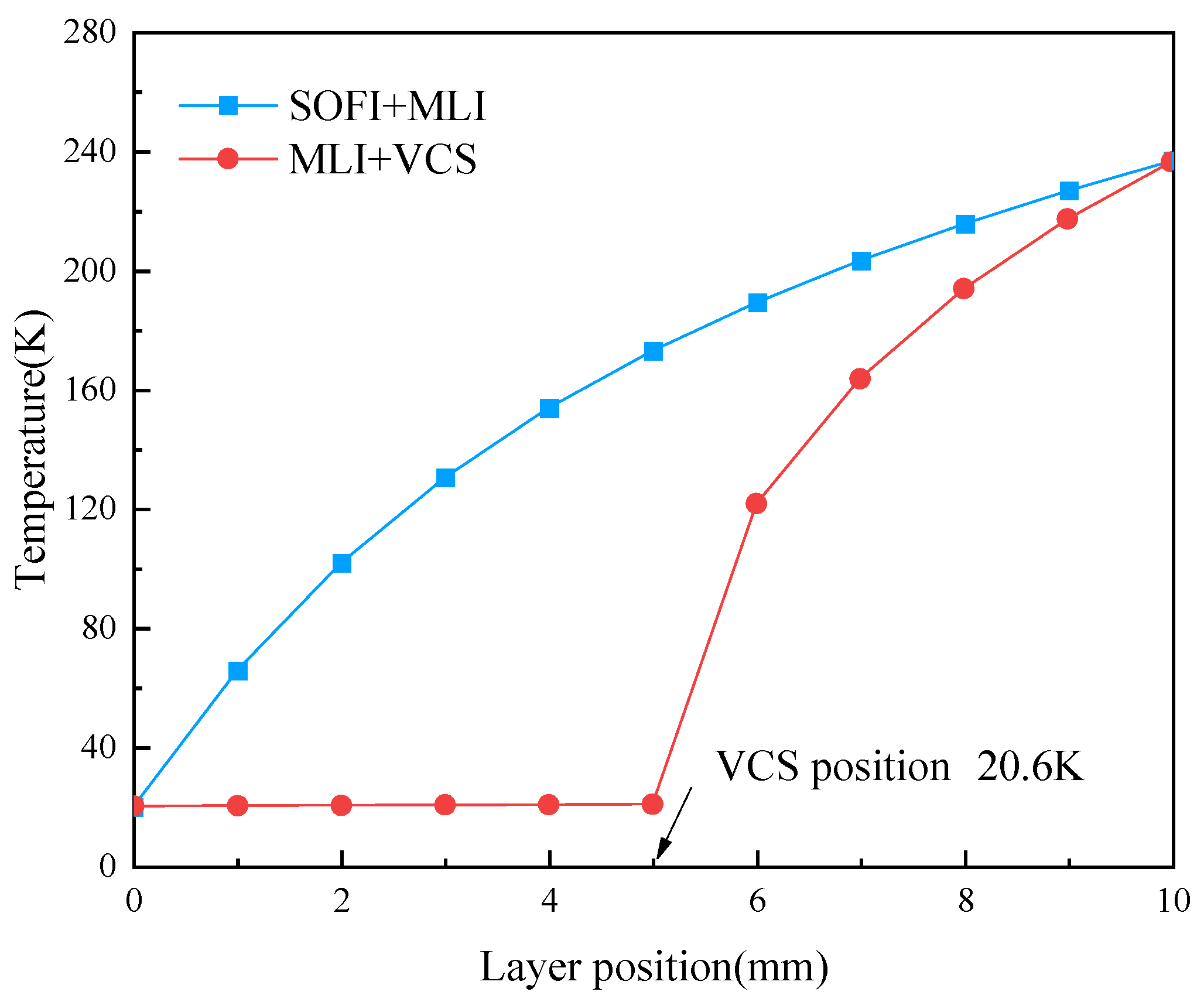
Figure 5 shows the temperature distribution of different adiabatic structures at the thermal equilibrium, where the VCS is located in the middle of the MLI adiabatic structure. In contrast to the general tank’s temperature profile, the interior’s temperature profile is practically flat. According to Table 1, the common bulkhead and metal joints are the main places from which heat escapes, which results in a significant amount of overall heat loss and evaporation exhaust. According Equation (25), when the gas flow in the VCS is considerable, the temperature change of the VCS is relatively minor. In the meantime, VCS absorbs most of the space radiation heat leak, so a very tiny amount of space radiation heat leak enters the tank. Consequently, while the outside temperature of MLI increases significantly, the interior temperature only changes slightly.
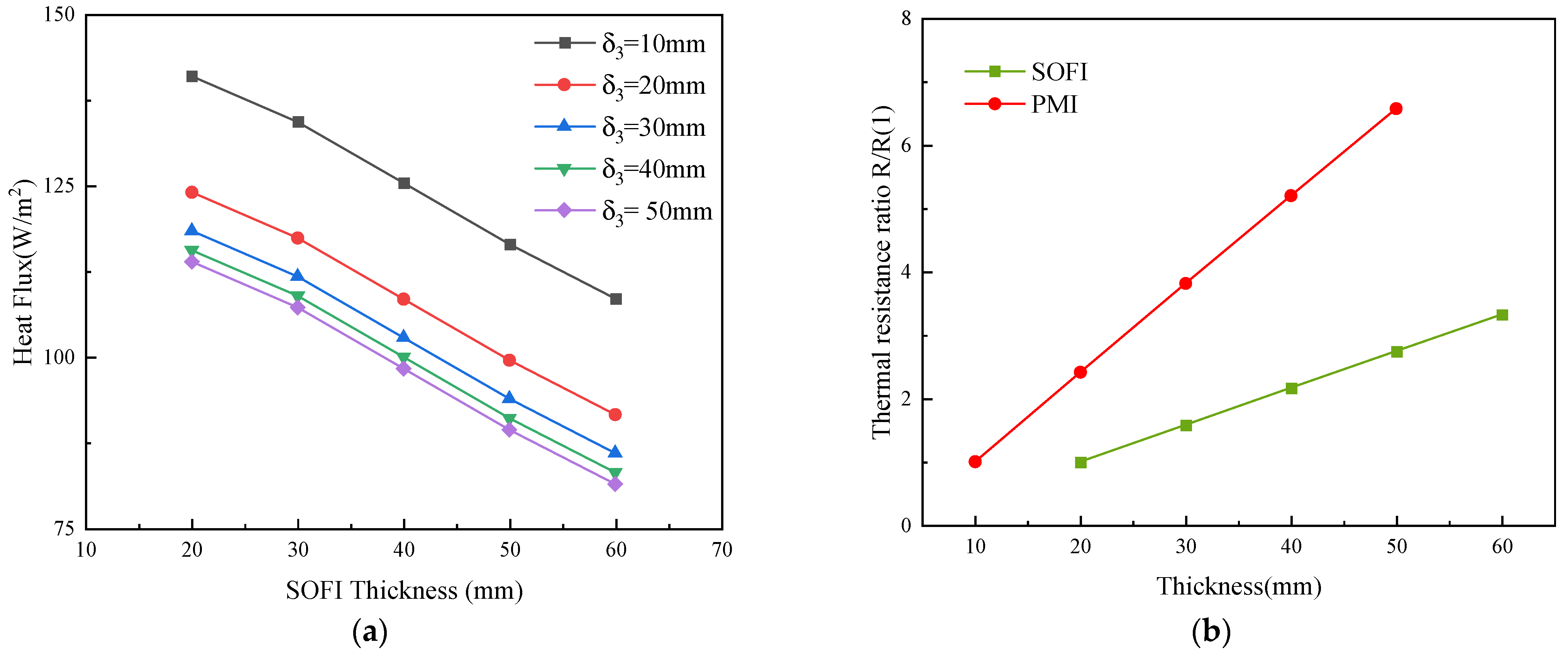
As shown in Table 1, space radiation heat (Q1) and common bulkhead heat conduction (Q2) are the most significant heat leak for the common bulkhead tank with SOFI. The sidewall of the tank is wrapped with SOFI to defend radiation heat. Polymethacrylimide (PMI) foam is material of the sandwich bulkhead. Figure 6 illustrates the heat flux and thermal resistance ratio of SOFI and PMI in different thicknesses. The thermal resistance of PMI increases more compared with SOFI for the same increased thickness. Therefore, for every 10 mm thickness increase in SOFI foam, the heat leakage is reduced by about 8 W/m2. However, the heat leak decreased by roughly 17 W/m2 as the PMI foam’s thickness (δ3) rose from 10 to 20 mm. Moreover, the effect of minimizing the heat leak is weaker as PMI foam thickness increases; this is due to the heat transfer coefficient equaling the reciprocal of the thermal resistance 1/R. When the thickness of SOFI and PMI was increased by the same amount, PMI was able to provide better insulation performance and required fewer insulation materials. Therefore, enhanced common bulkhead insulation is a better choice.
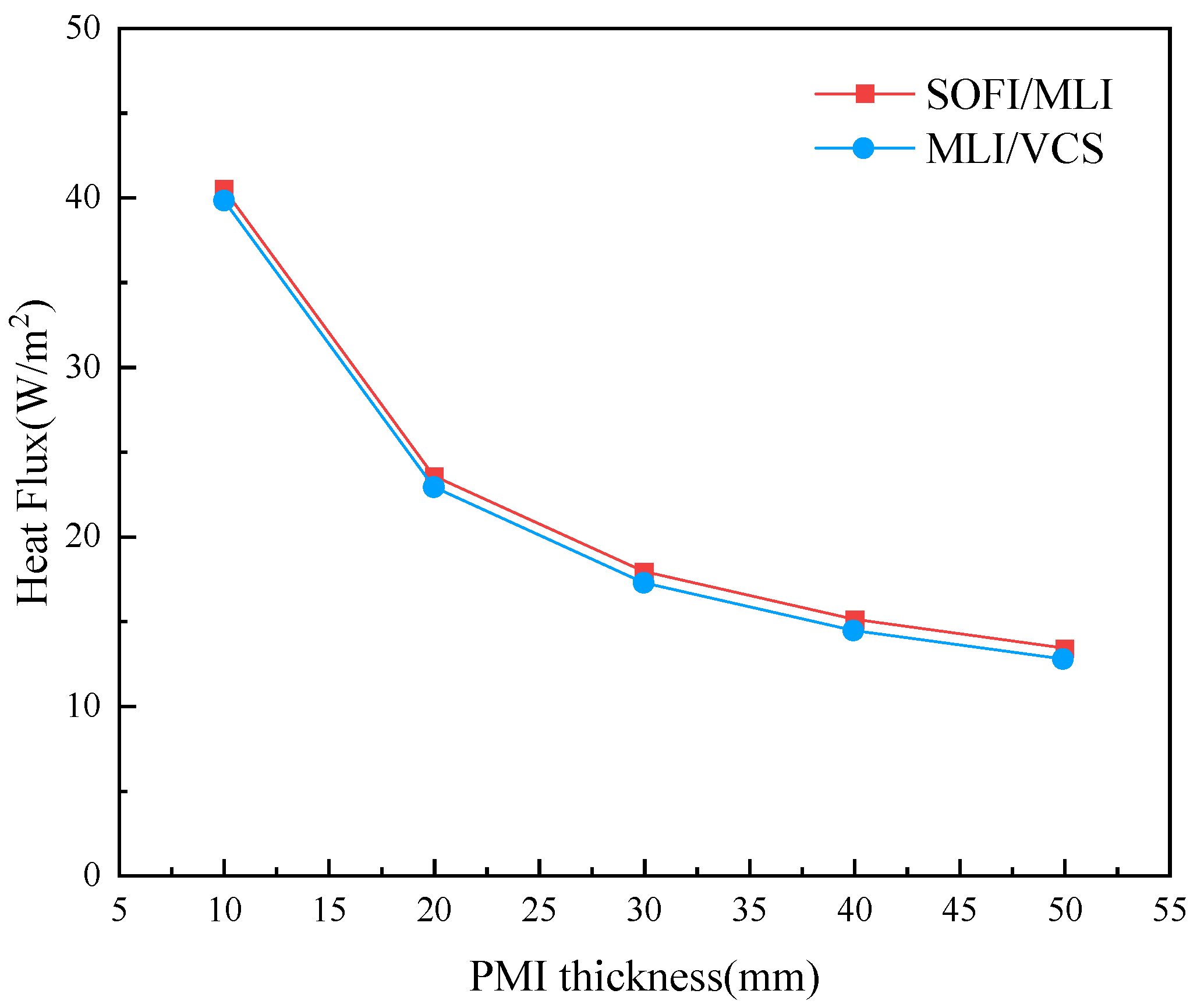
For the tank with MLI, the heat leak of the common bulkhead is dominant and needs to be weakened. Figure 7 analyzes the total heat leak of various thicknesses of the PMI foam. The thickness of MLI is 10 mm, with ten layers. When the thickness of PMI increases from 10 mm to 50 mm, the total heat flux of the tank with SOFI/MLI is reduced from 40.5 W/m2 to 13.4 W/m2. The VCS can recover the hydrogen gas sensible heat, which reduces the heat flux into the tank. However, the heat leak of sidewall adopted MLI/VCS only accounts for a small part of the total heat leakage. Therefore, the total heat leak flux of the tank with MLI/VCS is slightly lower than the tank without VCS. If the aim is to lessen the heat leakage from the common bulkhead tank, SOFI/MLI can satisfy the requirements without installing VCS. The total heat flux of the tank with MLI/VCS is reduced from 39.8 W/m2 to 12.7 W/m2. The total heat flux of the two tanks with MLI structure is reduced by about 68% when the PMI thickness increases from 10 mm to 50 mm, and the tank’s insulating performance is significantly enhanced.
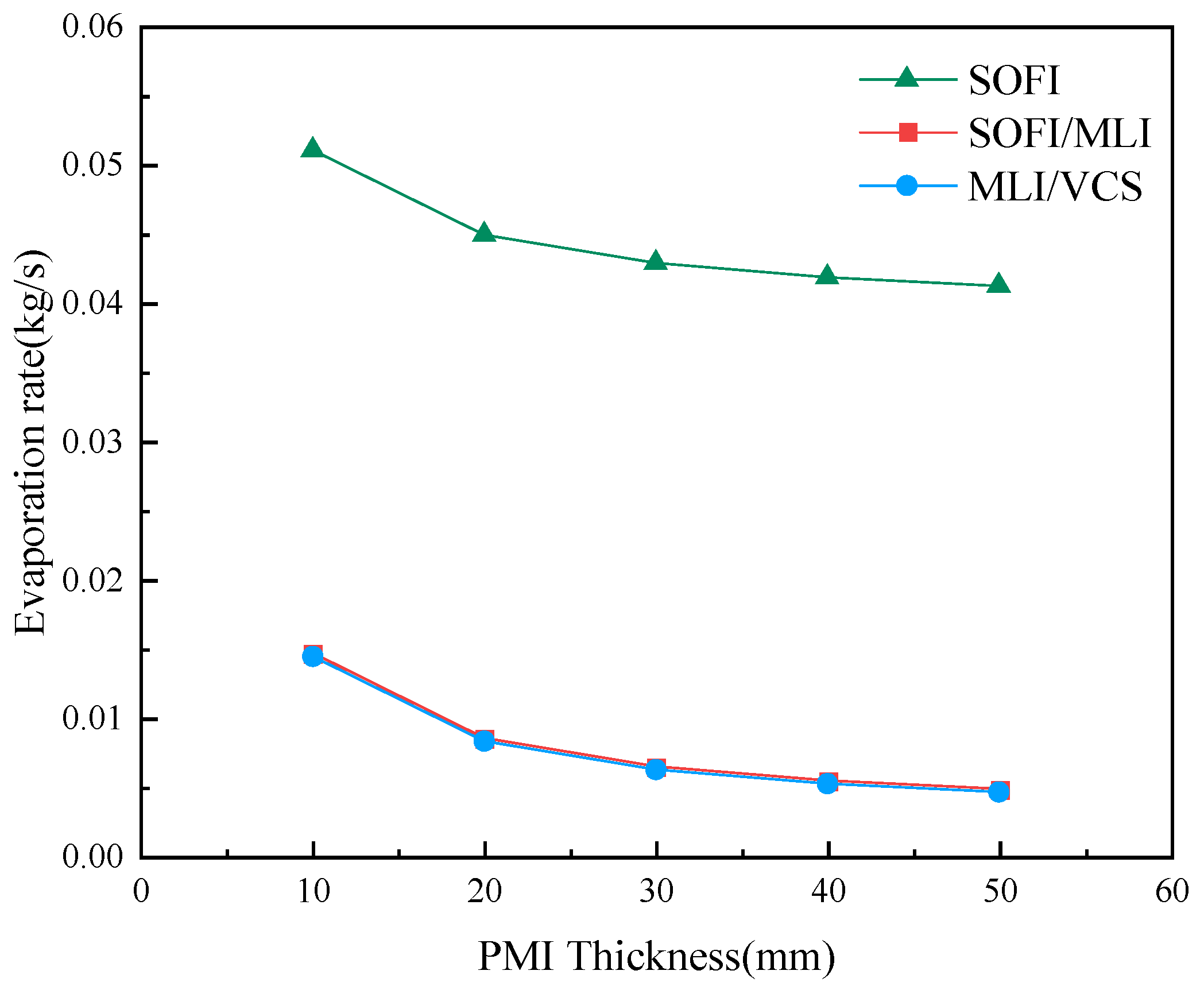
Considering heat leak factors such as space radiation, heat conduction of common bulkhead and metal joints, the liquid hydrogen evaporation under different adiabatic conditions is shown in Figure 8. The SOFI foam used in the research object is 20 mm thick. The thickness of the MLI is 10 mm, for a total of ten layers. In space, the evaporation rate of liquid hydrogen is 0.04~0.05 kg/s, adopting only SOFI and causing much fuel loss. The decrease in the evaporation rate is not particularly noteworthy with the PMI’s thickness increasing, due to the sidewall radiation leak being dominant. However, the heat leakage may be significantly reduced when the MLI structure is installed, which can limit radiation heat flow. The evaporation rate of liquid hydrogen is reduced to about 0.005~0.015 kg/s. To decrease fuel evaporation loss, it is recommended that MLI should be adopted for tanks in orbit condition.
3.2. Feasibility Analysis of Forward Exhaust Reorientation
Figure 9a displays the Laval nozzle’s outlet gas velocity under the adiabatic exhaust. The SOFI and SOFI/MLI insulation tank nozzles have similar outlet gas velocities (947.4 m/s on average). This is because the enthalpy and temperature of the inlet gas of the two nozzles are identical. Under the ideal adiabatic exhaust, the potential energy and kinetic energy of the gas are completely transformed into kinetic energy. According to Equation (34), although the exhaust flow is different in the two adiabatic conditions, the kinetic energy at the inlet being lower than the potential energy. The velocity mainly depends on the enthalpy of the inlet gas. Therefore, the outlet gas velocities of SOFI and SOFI/MLI insulation tanks are similar. For the tank with VCS, the outlet temperature of VCS and enthalpy of gas are higher, so the outlet velocity of the nozzle under adiabatic exhaust is larger than the other adiabatic forms. The heat leakage lowers as PMI thickness increases, which lessens the evaporation of liquid hydrogen in the tank. However, there is no significant change for the sidewall heat leak. The unit gas absorbs more heat during the recovery of sidewall heat leakage. Therefore, the enthalpy of the nozzle outlet gas increases, thereby increasing the outlet velocity and leading to the increase of the outlet velocity.
Figure 9b shows the forward exhaust acceleration of tanks under different adiabatic conditions. According to Equation (35), the acceleration by exhaust gas depends on the outlet velocity and exhaust flow. As shown in Figure 8 and Figure 9a, the nozzle outlet velocity of MLI/VCS insulation tank is higher, but the evaporation rate that corresponds to the exhaust flow is lower. Therefore, the final exhaust acceleration is slightly smaller than that of MLI. However, the exhaust flow of the tank only with SOFI insulation is significantly larger. Thus, the acceleration is greater. The literature [9] demonstrates that the propellant can settle effectively at an acceleration of 10−5 g. The acceleration generated by the SOFI insulation structure is more than 5.5 × 10⁻⁴ m/s2, which can achieve reorientation. MLI- and MLI/VCS-insulated tanks produce the similar acceleration through the exhaust. When the PMI thickness is less than 20 mm, with heat leak over 23 W/m2, the tank exhaust can accomplish reorientation. When the thickness of PMI is more than 30 mm, with heat leak below 18 W/m2, it is hard to achieve reorientation by exhausting with an acceleration of 8.7 × 10⁻⁵ m/s2.
3.3. Feasibility Analysis of Exhaust Rotation Reorientation
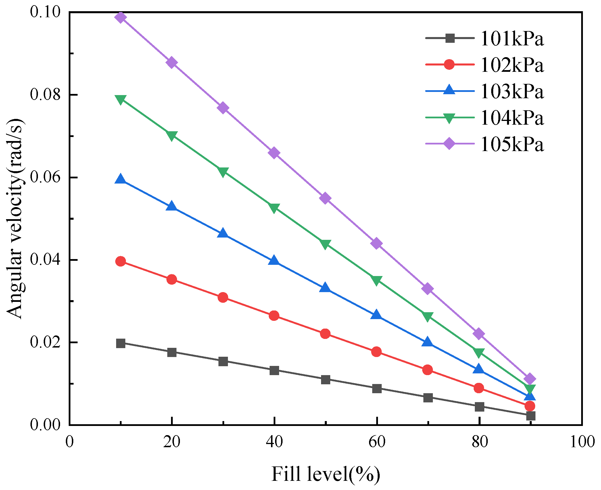
As mentioned earlier, the exhaust velocity of the Laval nozzle outlet of tanks with different adiabatic structures is not markedly different. Thus, the velocity at the nozzle exit is assumed to be uout = 950 m/s. Figure 10 shows the angular velocity of stable exhaust under different fill levels and pressure. The exhaust starts when the pressure reaches the upper limit. When the fill level drops and the initial exhaust pressure rises, the ullage area of the tank as well as the volume fraction of gas increases. As a result, there is more gas in the exhaust, and higher rotational angular velocity can be produced. The tank will rotate steadily in accordance with the angular velocity at the end of the accelerated exhaust under continuous exhaust. At a filling level of 10% and an exhaust pressure of 105 kPa, the steady exhaust angular velocity can reach 0.1 rad/s.
In a rotating tank, the liquid will distribute along the wall under the influence of centrifugal force, and the ullage is in the central region. At the beginning of reorientation, the gas and liquid are disorderly distributed, so the liquid center is not on the axis. The inertial force generated by each tiny particle in the tank cannot offset each other, thereby causing vibration and noise. When rotating at a low speed, the unbalance (centrifugal force F = mω2r and centrifugal couple) caused by rotation is small, and the vibration is slight. However, if the unbalance is significant at high speeds, the tank will vibrate significantly. Therefore, it is necessary to take measures to control the rotational speed, for example, through using flow-control valves.
3.4. Feasibility Analysis of Reorientation by TVS Technology
Hastings et al. [25] carried out on-orbit liquid hydrogen storage test experiments on the multipurpose hydrogen test bed (MHTB) of the Marshall Space Flight Center (MSFC). TVS tests were conducted on liquid hydrogen tanks with different heat leaks and filling levels. The ullage pressure control is within ±3.45 kPa. The results indicated that the shorter TVS duty cycle and bigger duty ratio corresponded to higher tank filling levels. The duty cycle of TVS is shorter for greater heat leaks. The working cycle of TVS is 1600~9600 s. Once the J-T exhaust starts, the average duty ratio of TVS is 1.25%~8.7%. For example, the literature [24] shows that for the tank with a liquid filling ratio of 50% and a heat flux of 1.45 W/m2, the TVS duty cycle is 5077 s, with a duty ratio of 1.9%. Ma et al. [26] compared the performance of TVS under the ground and microgravity conditions by simulation. The results showed that the exhaust cycle of TVS under microgravity is about four times that under the ground conditions. Therefore, the working cycle of TVS can be estimated as
where C is the microgravity amplification factor, 4; Δp is the pressure control range; Q is the heat leakage; and f is the filling rate.
In a TVS period, the gas exhaust rate from the tank equals the evaporation rate. The average flow rate of TVS exhaust is
where qg is the average flow rate of TVS exhaust; t0 is the TVS duty cycle; and η is the exhaust duty ratio.
The time required for reorientation of the common bulkhead tank [12] can be estimated as
where a is the forward thrust acceleration; XL is the distance from the edge of the liquid-vapor interface to the forward dome; L2 is the height of cylinder; R is the radius of the tank; and K is a coefficient, K = 0.5 at the fill level of 20%.
The TVS exhaust acceleration of tanks with different adiabatic conditions is shown in Figure 11. The forward thrust acceleration generated by exhaust is over 1.3 × 10⁻³ m/s2. Therefore, the acceleration generated by TVS exhaust can achieve effective propellant control.
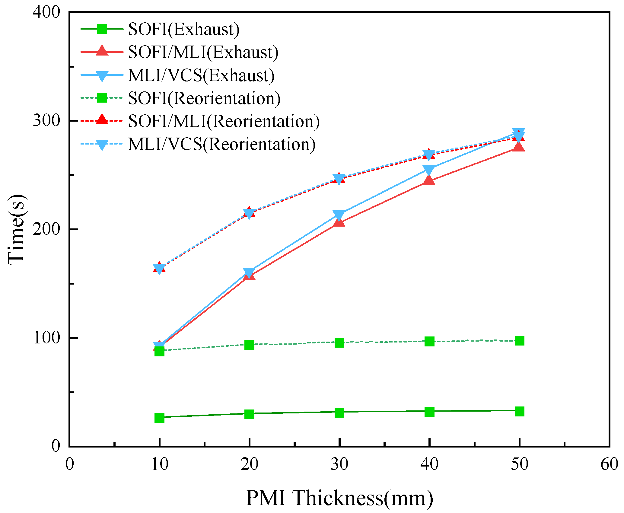
For the target tank, the pressure control band of TVS is ±3.45 kPa, with a filling rate of 20% and a duty cycle of 5%. The exhaust time and needed reorientation time of TVS under different PMI thicknesses are shown in Figure 12. In most cases, the TVS exhaust time is less than the time required for reorientation, and it is hard to achieve reorientation. However, when the thickness is 50 mm of the common bulkhead at the heat leakage of 12.7 W/m2 (see Figure 12), the fluid of the MLI/VCS insulation tank can be reorientated by evaporated exhaust gas.
4. Conclusions
The performance of the common bulkhead tank with three adiabatic structures in accomplishing thrust reorientation has been systematically studied. A thermodynamic balance model is established to study heat leak flux of the space liquid hydrogen tank. It may be possible to achieve forward and rotation reorientation using an evaporative exhaust. The following results are obtained:
- (1)
- Considering factors such as the space radiation through the insulation structure, heat conduction of the common bulkhead and metal thermal link, the heat leak for the liquid hydrogen tank with different adiabatic methods has been studied. For the SOFI adiabatic tank, the heat leak is 113.9~141.0 W/m2, in which space radiation is the major heat leak source; meanwhile, the common bulkhead heat conduction dominates in the adiabatic tank containing MLI, whose heat leak is 12.7~40.5 W/m2.
- (2)
- Under the condition of continuous stable adiabatic exhaust, the exhaust acceleration of the SOFI adiabatic tank is more than 5.5 × 10⁻⁴ m/s2, which can accomplish liquid hydrogen reorientation. For the tank that adopts MLI, available reorientation might be achieved in the case that the common bulkhead is thin enough (and the total heat leak is more than 23 W/m2).
- (3)
- The rotational angular velocity of the tank by the exhaust increases with the fill level dropping and the initial exhaust pressure rising, thereby leading to a more effective reorientation by rotation. However, the system might be instable at a high rotating speed, which should be carefully considered.
- (4)
- The exhaustion of TVS can achieve effective propellant control, since the acceleration generated by the intermittent exhaustion of TVS may maintain a relatively high level within sufficient time, even if the tank is in good thermal insulation. For the TVS tank with a cycle duty ratio of 5%, the exhaust forward thrust acceleration can reach 1.3 × 10⁻⁴ g in good thermal insulation, and the exhaust duration is slightly larger than the time needed for reorientation.
Author Contributions
Conceptualization, Y.L. and Y.M.; methodology, J.L. and L.W.; writing—original draft preparation, J.L.; writing—review and editing, Y.M., Y.L. and L.W.; supervision, Y.L. and Y.M.; project administration, L.W. and X.L. All authors have read and agreed to the published version of the manuscript.
Funding
This research was funded by National Natural Science Foundation of China (Grants No: 51976151).
Data Availability Statement
Not applicable.
Conflicts of Interest
The authors declare no conflict of interest.
Abbreviations
| SOFI | Spray-on foam insulation |
| MLI | Multilayer insulation |
| VCS | Self-evaporation vapor cooled shield |
| TVS | Thermodynamic vent system |
| PMD | Propellant management device |
| PMI | Polymethacrylimide |
References
- Chato, D. Cryogenic technology development for exploration missions. In Proceedings of the 45th AIAA Aerospace Sciences Meeting and Exhibit, Reno, Nevada, 8–11 January 2007; p. 953. [Google Scholar]
- Clark, J.A. Cryogenic Heat Transfer. Adv. Heat Transf. 1969, 5, 325–517. [Google Scholar]
- Johnson, W. Thermal analysis of low layer density multilayer insulation test results. AIP Conf. Proc. 2012, 1434, 1519–1526. [Google Scholar]
- Zheng, J.; Chen, L.; Wang, J.; Xi, X.; Zhu, H.; Zhou, Y.; Wang, J. Thermodynamic analysis and comparison of four insulation schemes for liquid hydrogen storage tank. Energy Convers. Manag. 2019, 186, 526–534. [Google Scholar] [CrossRef]
- Liu, Z. Progress of study on long-term in-orbit pressure management technique for cryogenic propellant. J. Astronaut. 2014, 35, 254–261. [Google Scholar]
- Hastings, L.; Tucker, S.; Flachbart, R.; Hedayat, A.; Nelson, S. Marshall space flight center in-space cryogenic fluid management program overview. In Proceedings of the 41st AIAA/ASME/SAE/ASEE Joint Propulsion Conference & Exhibit, Tucson, Arizona, 10–13 July 2005; p. 3561. [Google Scholar]
- Zhen, L.; Chu, G.; Hong, L.; Wang, L. Propellant Management of Rocket Upper Stage in Microgravity Environment. Missiles Space Veh. 2012, 4, 20–26. [Google Scholar]
- Hastings, L.J.; Platt, G.K.; Swalley, F.E. Saturn V low gravity fluid mechanics problems and their investigation by full-scale orbital experiment. In Proceedings of the Fluid Mechanics and Heat Transfer Under Low Gravity, Palo Alto, CA, USA, 24–25 June 1965; p. 1. Available online: https://citeseerx.ist.psu.edu/document?repid=rep1&type=pdf&doi=dbe99bc51b1842adb8942d69176eaff4739879f1#page=27 (accessed on 15 March 2023).
- Kutter, B.; Oneil, G.; Pitchford, B.; Zegler, F. A practical, affordable cryogenic propellant depot based on ULA’s flight experience. In Proceedings of the AIAA Space 2008 Conference & Exposition, San Diego, CA, USA, 9–11 September 2008; p. 7644. [Google Scholar]
- Tam, W.; Lay, W.; Hersh, M.; Jaekle, D., Jr.; Epstein, S. Design, development, qualification, and manufacture of the HS 601 propellant tank. In Proceedings of the 32nd Joint Propulsion Conference and Exhibit, Lake Buena Vista, FL, USA, 1–3 July 1996; p. 2748. [Google Scholar]
- Salzman, J.A.; Masica, W.J. Experimental Investigation of Liquid-Propellant Reorientation; National Aeronautics and Space Administration: Washington, DC, USA, 1967; Volume 3789.
- Salzman, J.A.; Masica, W.J.; Lacovic, R.F. Low Gravity Reorientation in a Scale-Model Centaur Liquid-Hydrogen Tank; Lewis Research Center: Cleveland, OH, USA, 1973. [Google Scholar]
- Hung, R.J.; Shyu, K.L. Space-Based Cryogenic Liquid-Hydrogen Reorientation Activated By Low-Frequency Impulsive Reverse Thruster of Geyser Initiation. Acta Astronaut. 1991, 25, 709–719. [Google Scholar] [CrossRef]
- Hung, R.; Lee, C.; Shyu, K. Reorientation of rotating fluid in microgravity environment with andwithout gravity jitters. J. Spacecr. Rocket. 1991, 28, 71–78. [Google Scholar] [CrossRef]
- Li, Z.; Liu, Q.; Liu, R. Investigation of Gas-Liquid Interface Behavior on Propellant Reorientation in Microgravity Environment. J. Jpn. Soc. Microgravity Appl. 2011, 28, 120. [Google Scholar]
- Li, Z.-G.; Zhu, Z.-Q.; Liu, Q.-S.; Lin, H.; Xie, J.-C. Simulating propellant reorientation of vehicle upper stage in microgravity environment. Microgravity Sci. Technol. 2013, 25, 237–241. [Google Scholar] [CrossRef]
- Zhang-Guo, L.; Qiu-Sheng, L.; Rong, L.; Wei, H.; Xin-Yu, D. Influence of Rayleigh–Taylor Instability on Liquid Propellant Reorientation in a Low-Gravity Environment. Chin. Phys. Lett. 2009, 26, 114701. [Google Scholar] [CrossRef]
- Liu, Z.; Sun, P.; Li, P. Research on thermal stratification of cryogenic liquid oxygen tank in microgravity. Cryogenics 2016, 209, 25–31. [Google Scholar]
- Uher, C. Thermal Conductivity of Pure Metals and Alloys/Wärmeleitfähigkeit von Reinen Metallen Und Legierungen; Springer: Berlin/Heidelberg, Germany, 1991; Volume 3. [Google Scholar]
- Liu, Y.; Wu, R.; Yang, P.; Wang, T.; Liu, H.; Wang, L. Parameter study of the injection configuration in a zero boil-off hydrogen storage tank using orthogonal test design. Appl. Therm. Eng. 2016, 109, 283–294. [Google Scholar] [CrossRef]
- Wang, B.; Huang, Y.; Li, P.; Sun, P.; Chen, Z.; Wu, J. Optimization of variable density multilayer insulation for cryogenic application and experimental validation. Cryogenics 2016, 80, 154–163. [Google Scholar] [CrossRef]
- Zhu, H.; Huang, Y.; Xu, Y.; Wu, J.; Li, P. Performance optimization and analysis of variable density multilayer insulation. Cryogenics 2011, 184, 42–46. [Google Scholar]
- Jiang, W.; Zuo, Z.; Huang, Y.; Wang, B.; Sun, P.; Li, P. Coupling optimization of composite insulation and vapor-cooled shield for on-orbit cryogenic storage tank. Cryogenics 2018, 96, 90–98. [Google Scholar] [CrossRef]
- Zheng, J.; Chen, L.; Wang, J.; Zhou, Y.; Wang, J. Thermodynamic modelling and optimization of self-evaporation vapor cooled shield for liquid hydrogen storage tank. Energy Convers. Manag. 2019, 184, 74–82. [Google Scholar] [CrossRef]
- Hastings, L.; Flachbart, R.; Martin, J.; Hedayat, A.; Fazah, M.; Lak, T.; Nguyen, H.; Bailey, J. Spray Bar Zero-Gravity Vent System for On-Orbit Liquid Hydrogen Storage; National Aeronautics and Space Administration: Washington, DC, USA, 2003.
- MA, Y. Optimized analysis and performance study on thermodynamic vent system in cryogenic fuel tank. Cryog. Supercond. 2014, 42, 10–15. [Google Scholar]
Figure 1.
Geometry of liquid container.

Figure 2.
Schematic of insulation system for LH2 tank. (a) SOFI; (b) SOFI/MLI; (c) MLI/VCS.

Figure 3.
Common bulkhead metal joints of the tank.

Figure 4.
Flow chart of layer-by-layer method for MLI and VCS.

Figure 5.
Temperature profile within insulation at thermal equilibrium.

Figure 6.
Insulation performance of different thickness for SOFI and PMI: (a) heat flux of different SOFI thicknesses; (b) thermal resistance K of different thermal insulation material thickness compared with the thermal resistance of the first thickness.
Figure 6.
Insulation performance of different thickness for SOFI and PMI: (a) heat flux of different SOFI thicknesses; (b) thermal resistance K of different thermal insulation material thickness compared with the thermal resistance of the first thickness.

Figure 7.
Heat flux under different adiabatic conditions.

Figure 8.
Liquid hydrogen evaporation under different adiabatic conditions.

Figure 9.
Parameters of the exhaust gas under different adiabatic conditions: (a) Laval nozzle’s outlet gas velocity; (b) forward exhaust acceleration.
Figure 9.
Parameters of the exhaust gas under different adiabatic conditions: (a) Laval nozzle’s outlet gas velocity; (b) forward exhaust acceleration.

Figure 10.
The angular velocity of stable exhaust under different fill levels and pressures.

Figure 11.
Acceleration by exhaustion of TVS.

Figure 12.
Exhaust and reorientation time under different adiabatic conditions.


Table 1.
Comparison of heat leak under different adiabatic conditions.
| Adiabatic Conditions | SOFI | MLI | MLI/VCS |
|---|---|---|---|
| Tout/outer temperature of the insulator, K | 100.9 | 236.9 | 236.6 |
| Q1/space radiation heat, W | 16,451.7 | 112.0 | 0.2 |
| QVCS/heat absorbed by the VCS, W | - | - | 201.0 |
| Q2/common bulkhead heat conduction, W | 5538.7 | 5538.7 | 5538.7 |
| Q3/metal joints heat conduction, W | 937.0 | 937.0 | 937.0 |
| Qtank/total heat leak of the tank, W | 22,927.4 | 6587.7 | 6475.9 |
| Heat flux/total heat flux of the tank, W∙m2 | 141.0 | 40.5 | 39.8 |
Disclaimer/Publisher’s Note: The statements, opinions and data contained in all publications are solely those of the individual author(s) and contributor(s) and not of MDPI and/or the editor(s). MDPI and/or the editor(s) disclaim responsibility for any injury to people or property resulting from any ideas, methods, instructions or products referred to in the content. |
© 2023 by the authors. Licensee MDPI, Basel, Switzerland. This article is an open access article distributed under the terms and conditions of the Creative Commons Attribution (CC BY) license (https://creativecommons.org/licenses/by/4.0/).
Share and Cite
MDPI and ACS Style
Liang, J.; Ma, Y.; Li, Y.; Wang, L.; Luo, X. Feasibility Study on Space Reorientation for Liquid Hydrogen Tanks by Means of Evaporated Exhaust Gas. Processes 2023, 11, 1278. https://doi.org/10.3390/pr11041278
AMA Style
Liang J, Ma Y, Li Y, Wang L, Luo X. Feasibility Study on Space Reorientation for Liquid Hydrogen Tanks by Means of Evaporated Exhaust Gas. Processes. 2023; 11(4):1278. https://doi.org/10.3390/pr11041278
Chicago/Turabian StyleLiang, Jiajia, Yuan Ma, Yanzhong Li, Lei Wang, and Xiaozhong Luo. 2023. "Feasibility Study on Space Reorientation for Liquid Hydrogen Tanks by Means of Evaporated Exhaust Gas" Processes 11, no. 4: 1278. https://doi.org/10.3390/pr11041278
Note that from the first issue of 2016, this journal uses article numbers instead of page numbers. See further details here.