Article

Layering Vibration Transfer Path Analysis of a Flexible Supported Gear System Based on the Vibration Power Flow Theory

1
School of Mechanical Engineering, Taiyuan University of Science and Technology, Taiyuan 030024, China
2
Shaanxi Engineering Laboratory for Transmissions and Controls, Northwestern Polytechnical University, Xi’an 710072, China
*
Author to whom correspondence should be addressed.
Processes 2023, 11(4), 1233; https://doi.org/10.3390/pr11041233
Submission received: 1 April 2023 / Revised: 14 April 2023 / Accepted: 14 April 2023 / Published: 16 April 2023

Abstract

:
In the marine gear system, the vibration of gears is transmitted to the ship foundation through shafts, bearings, housing, and isolators, and then the underwater noise is generated. Analyzing the vibration transfer properties and identifying the critical path can provide guidance to the low-noise design of the gear system. In this paper, a coupled gear-housing-foundation dynamic model is proposed for a flexible supported gear system, in which the flexibility of each subsystem and the coupling relationship between them are taken into account. The transferring process of gear vibration is divided into different layers between gears, shafts, bearings, housing, isolators, and ship foundation. Based on the vibration power flow (VPF) theory, detailed layering vibration transfer path analyses of the gear isolation coupled system are carried out for both location path and direction path, and the main paths are identified in a broad speed range. The results indicate that though the gear vibration transferred to the foundation attenuate layer by layer, there may be reverse VPF in some special location path and direction path under resonance conditions.

1. Introduction

The vibration of marine gears is transferred through the shaft, bearing, housing, and isolator to the ship foundation. According to roles in the vibration transfer process, the system is composed of tripartite: excitation source, transmission path, and receiver. The gear pair acts as the excitation source, the ship foundation serves as the receiving structure, and the shafts, bearings, housing, and isolators formed the transfer paths. These paths can further be divided in detail according to the location or direction of vibration transferring. To decrease the foundation’s vibration, on the one hand, technologies such as gear tooth modification can be adopted to reduce the excitation [1]; on the other hand, the vibration transfer process can be controlled to reduce the transferring of vibration energy between each layer [2]. The purpose of vibration transfer control is to minimize the vibration energy entered into the receiver and distribute the vibration energy in the receiving structure as reasonably as possible. For passive control or structural modification to achieve vibration reduction, it is very important to conduce the transfer path analysis (TPA) and identify the main paths.
To carry out the TPA, a complete system dynamic model is required. Currently, research on gear systems and vibration isolation systems (VIS) are independent of each other. The gear system dynamic analysis stars with a lumped parameter model of the transmission system [3], assuming a rigid housing and constraining the bearings to rotate only, including the time-varying mesh stiffness (TVMS) and transmission error (TE) excitation, and calculate the bearing vibration. Then, a housing finite element (FE) model is adopted [4,5], in which the isolation system is treated as simplified springs to obtain the dynamic response of the housing foot. When analyzing the isolation system, the gearbox is regarded as rigid mass and the excitation is treated as simple harmonic. Then the transmissibility of the vibration isolation system is analyzed [6]. Finally, the vibration acceleration transferred to the ship foundation is determined based on the dynamic response of the housing foot and the transmissibility of the vibration isolation system. Although some scholars coupled the transmission system with housing, the gearbox and VIS remain separated [7,8,9,10,11].
Some papers presented research on the vibration transferring in a gear system that contains a geared transmission system and housing. The frequency response function characterizes the relationship between the steady-state output and input of the system in the frequency domain, which is of great help for vibration transfer analysis. Guo [12] measured the frequency response function of a gear-bearing-housing system. In the gear system, the vibration of the gears is sequentially transferred to the housing through the shaft and bearings. Based on a simplified 8 degree of freedom (DOF) dynamic model, Xiao [13] found that the major vibration reduction appears during the transfer process from the inner ring to the outer ring of bearings, and the least attenuation occurs during the transfer from the outer ring to the housing. In traditional gear system dynamics analysis, the transmission system and the housing are independent, and the bearings serve as a bridge connecting the transmission system and the housing, playing a significant role in vibration transferring. To investigate the contribution of bearing on the vibration transferring, Vanhollebeke [14] treated each bearing as a separate vibration transfer path and identified the main one. Incorporating the flexibility of the housing into the transmission system can provide a more reasonable analysis of dynamic response and vibration transferring. Xu [15] developed a coupled dynamic model of the gear and casing, and analyzed the danger resonance path. For planetary transmissions, the vibration transfer path is more complex. Nie [16] built a multiple transfer path model from each mesh point to the ring gear sensor for the wind power gearbox.
There is a large amount of research on the TPA of a vibration isolation system. In a vibration isolation system, each isolator acts as a transfer path during the vibration transfer process. Liu [17] explored how different suspension components contributed to the structure-borne noise transmission into a railroad vehicle due to wheel/rail forces that resulted from random surface roughness. The traction rods and lateral dampers are both significant structure-borne pathways, according to the results. In order to reduce the compliance and mobility transfer function of a single degree of freedom system under a harmonic ground acceleration excitation, Baduidana [18] deduced the optimal values of inerter-based isolators. Li [19] built a dynamic model for the double-layer marine reducer box with an elastic element connecting the exterior and interior cases, and performed transfer path contribution analysis for each excitation separately based on the force transmissibility index. Results show that the primary channel is the last elastic element that should be given priority during the vibration reduction design process. The VPF index can more properly represent the nature of vibration energy propagation than the traditional force transmissibility and motion transmissibility index, and thus yield wide usage in the dynamic analysis of a vibration isolation system [20,21,22]. Similarly, transfer path analysis based on the VPF index is more reasonable than the traditional TPA. Yang [23] ranked the vibration contribution provided by all paths to the target body and identified the critical path based on the VPF theory for an offshore vehicle power device. Lee [24] recognized the main vibration transfer path of a test vehicle by measuring the VPF through the 18 isolators.
There is little research on the vibration characteristics and transferring assessments of gear isolation coupled system. Yang [25] constructed a housing FE model in which vibration isolators are considered as spring-damper elements, then extracted the physical parameters of the housing, built a gear-housing-isolation coupled dynamic system based on mass, damping, and stiffness variables, and finally studied the influence of stiffness and the number of isolators on the system vibration response. Luan [26] coupled the planetary gear transmission system with the double-layer box through MASTA software, and analyzed the vibration reduction effect of isolators between the dual box. Ren compared the VPF entered into the hull base between different vibration isolation types for a marine gearbox [27] and compared the arrangement of elastic isolators on the dynamic response of the hull base [28].
A detailed TPA based on an integrated gear-housing-isolation model and the VPF theory can provide effective guidance for low-noise design of marine transmission systems. In this paper, a flexible supported gear system is divided into different layers according to the vibration transferring process, that is, gear, shaft, bearing, housing, isolator, and foundation. According to the location and direction of vibration transferring, the VPF index is adopted to analyze the detailed transfer characteristics, and the main paths are identified in a broad speed range.

2. Dynamic Modeling

2.1. Model Description

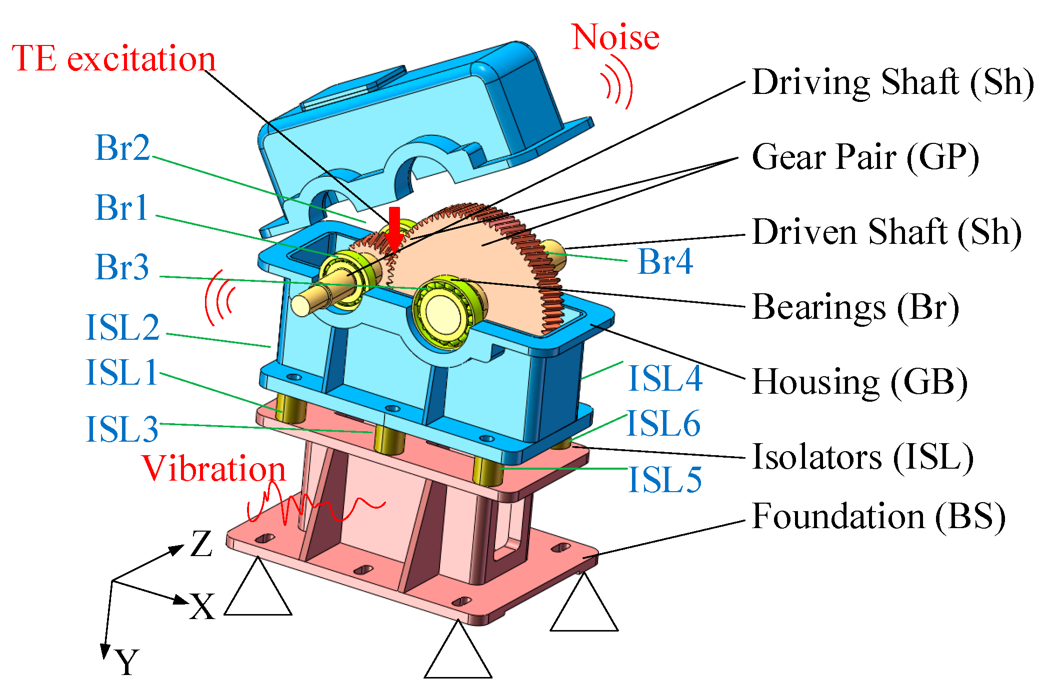
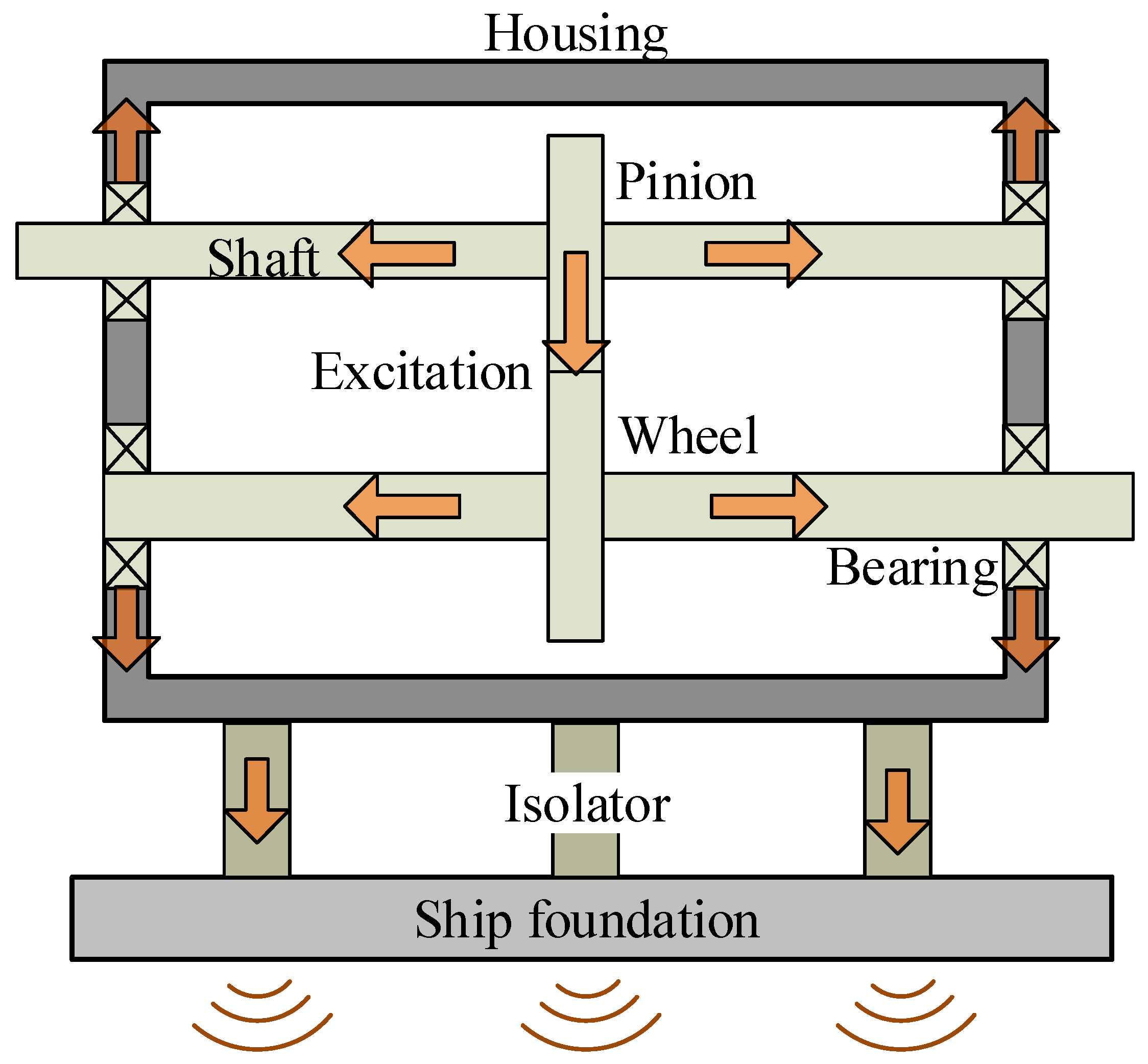
In order to decrease the gear vibration transferring to the ship foundation, gear devices are typically installed through elastic elements. The commonly used VIS is single-layer configuration. Figure 1 shows the gear isolation system adopted in this study. Br1, Br2, Br3, and Br4 are the 1st, 2nd, 3rd, and 4th bearing, respectively. ISL1, ISL2, ISL3, ISL4, ISL5, and ISL6 are the 1st, 2nd, 3rd, 4th, 5th, and 6th isolators, respectively. The speed of the driving shaft ranges from 50 r/min to 15,000 r/min, and the torque applied on the driven shaft is 1200 N·m.
Continuous models have advantages over the lumped mass ones in describing the vibration transferring characteristics, because it can model the system dynamic properties in a more exact way. For this reason, with the exception of gears and bearings, which are modelled using lumped parameters, all subsystems are modelled as a continuum in this study. Each node has six-DOF, {ux, uy, uz, rotx, roty, rotz}, namely translational motion along the x-axis, y-axis, z-axis, and rotation around the x-axis, y-axis, and z-axis, respectively.
In this study, only the TE excitation of gears is applied and other excitations are overlooked, since the TE excitation is the primary reason for the generation of vibration and noise [1,29]. This study also excludes the non-linear items, such as gear backlash from the calculation, due to the linear feature of the gear system and the difficulty for the impedance model to directly consider the non-linear terms.

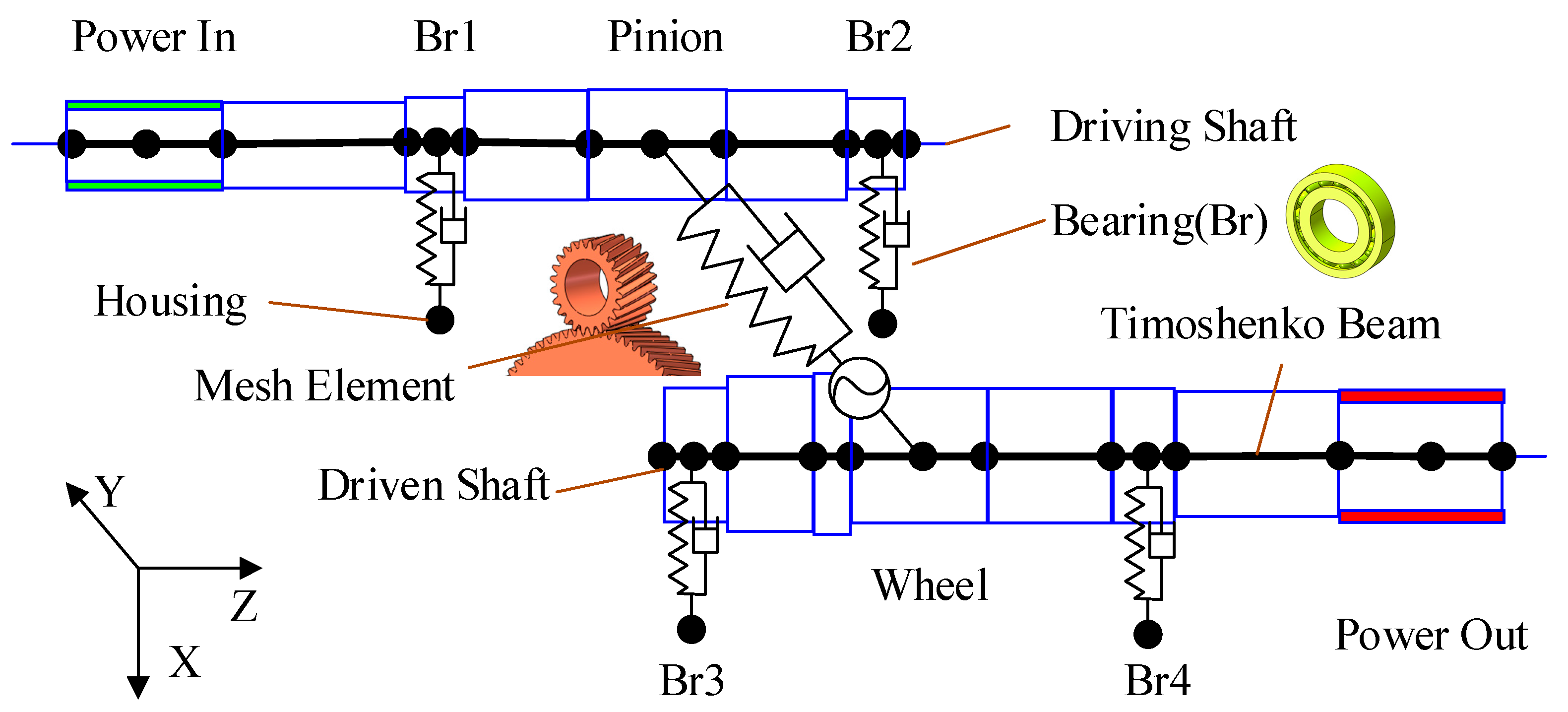
2.2. Transmission System Modeling

A single-stage helical geared transmission system is used in this study, and the dynamic model is shown in Figure 2.
The dynamic equation of a gear system is described [9]:
M GP x ¨ GP ( t ) + C GP x ˙ GP ( t ) + K GP ( t ) ( x GP ( t ) e GP ( t ) ) = f GP ( t )
where x GP is the displacement vector of nodes, M GP is the mass matrix of gears, C GP = c GP V V T is the mesh damping matrix, c GP is the mesh damping, K GP = k GP V V T is the mesh stiffness matrix, k GP is the normal mesh stiffness, f GP is the reaction load vector of shaft, e GP is the general mesh error vector, the superscript GP denotes the gear pair subsystem, V is the project vector transferring displacement in the global coordinate to the line of action, and VT is the transposition of V [9].
Let x equal x s for approximation, then Equation (1) can be simplified to the following linear equation:
M GP x ¨ GP ( t ) + C GP x ˙ GP ( t ) + K 0 GP x GP ( t ) = f GP ( t ) + f e x t ( t )
where f e x t ( t ) = K 0 GP x s GP ( t ) is the transmission error excitation, K 0 GP is the mean mesh stiffness of gear pair, i.e., mean ( K GP ( t ) ).
For linear gear systems, the time-varying parameters in Equation (2) are periodic. So after removing the mean term and performing Fourier transform, the frequency form of Equation (2) yields.
M GP X ¨ GP ( ω ) + C GP X ˙ GP ( ω ) + K GP X GP ( ω ) = F GP ( ω ) + F e x t ( ω )
where X GP ( ω ) is the displacement vector in a frequency form, F GP ( ω ) is the reaction load in the frequency domain, and F e x t ( ω ) is the TE load in the frequency domain.
Let Z GP ( ω ) = j ω M GP + C GP + K 0 GP / ( j ω ) and V GP ( ω ) = j ω X GP ( ω ) , then Equation (3) can be expressed as an impedance form:
Z GP ( ω ) V GP ( ω ) = F GP ( ω ) + F e x t ( ω )
where Z GP is the impedance matrix of mesh element, and V GP is the frequency velocity vector.
Using a generic FE approach, the shaft is modeled. Depending on the diameters and the location of the power points and support points, it is divided into a number of shaft segments. Timoshenko beam elements with two nodes and six DOF per node are used to simulate each shaft segment. The equation of motion is given:
M s h i x ¨ s h i ( t ) + C s h i x ˙ s h i ( t ) + K s h i x s h i ( t ) = f s h i ( t )
The governing motion equation can be obtained in the following manner after putting together sufficient matrices for each shaft section and taking into account the influence of external load:
M S h x ¨ S h ( t ) + C S h x ˙ S h ( t ) + K S h x S h ( t ) = f S h ( t )
where M S h , C S h , and K S h are the mass matrix, damping matrix and stiffness matrix of shaft subsystem, respectively, x S h is the node displacement vector, f S h is the external load, and the superscript Sh denotes the shaft subsystem.
The shaft subsystem’s impedance equation can be calculated in the form of:
Z S h ( ω ) V S h ( ω ) = F S h ( ω )
where Z S h ( ω ) = j ω M S h + C S h + K S h / ( j ω ) is the impedance matrix, V S h ( ω ) = j ω X S h ( ω ) is the velocity vector in the frequency domain, X s h ( ω ) is the frequency domain form of x s h ( t ) , and F S h is the external load vector of shaft system.
The bearing is modeled by the Lim model [30]. According to the load–displacement relationship derived by setting up contact between the bearing rollers and the inner and outer rings, and establishing the force balance equation, the one-node form complete stiffness matrix with 6 × 6 order is given by:
K m = [ F i m j m F i m θ j m M i m j m M i m θ j m ] ,   ( i , j =   x ,   y ,   z ) .
In this paper, the bearing is made up of two nodes. The first node is attached to the shaft, while the second one is attached to the housing. The matrix of two-node form stiffness results in:
K B r = [ K m K m K m K m ] .
After considering the damping characteristics, the bearing’s impedance matrix is obtained as follows:
Z B r ( ω ) = C B r + K B r / ( j ω )
where C B r is the damping of the bearing, j = 1 is the complex number, and the superscript Br denotes the bearing subsystem.
By applying the external load, the bearing subsystem’s impedance equation is written:
Z B r ( ω ) V B r ( ω ) = F B r ( ω ) .

2.3. Housing Modeling

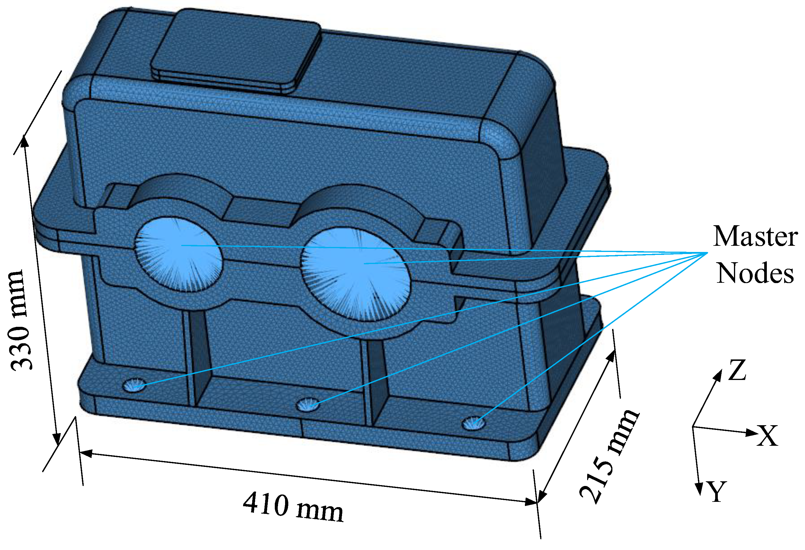
The housing in this research measures 410 mm in length, 215 mm in width, and 330 mm in height. The material is S355B (according to ISO 630-2), which has a density of 7850 kg/m3, a Young’s modulus of 2.07 × 10¹¹ Pa, a Poisson’s ratio of 0.3, and a damping ratio of 2%.
The housing is meshed using a 4-node tetrahedron with a 5 mm element size, and 315,000 elements and 76,000 nodes make up the FE model. Ten master nodes, including four bearing nodes and six isolator nodes, is created and meshed with a six-DOFs mass element. These master nodes are coupled with the bearing holes or bolt holes, respectively. Figure 3 illustrates the construction of the FE model. The first 500 modes are obtained from the modal analysis using the block Lanczos method [31,32].
The mobility matrix of the housing can be described as a 60 × 60 matrix as there are ten external nodes in the housing, and each node offers six-DOF.
Y = [ Y 11 Y 12 Y 1 n Y 22 Y 2 n S y m . Y n n ]
Each mobility element Y l p can be calculated through Equation (13):
Y l p ( ω ) = j ω r = 1 n u l r u p r K r ω 2 M r + j ω C r
where K r , M r , and C r are the modal stiffness, modal mass, and modal damping, respectively, u is the modal shape, r is the modal order, l = 1 : 10 , and p = ux, uy, uz, rotx, roty, rotz.
The inversion of the mobility matrix will produce the housing’s impedance matrix.
Z GB ( ω ) = Y GB ( ω ) 1
The housing’s impedance equation can be generated in the form of:
Z GB ( ω ) V GB ( ω ) = F GB ( ω )
where the superscript denotes the housing subsystem.

2.4. Isolator and Foundation Modeling

This study utilizes the rubber isolator, which is frequently applied in the field of engineering. Poisson’s ratio is 0.49, density is 1000 kg/m3, the loss factor is 0.1, and the elastic modulus is 1 × 10⁷ Pa. The shape of the isolator is a cylinder with 40 mm diameter and height. The isolator is modeled as a continuous Timoshenko beam element.
Considering the torsional, axial, and flexural vibration, the state vector relationship between the two ends of the isolator can be arranged as a transfer matrix form:
{ q F } l = [ T 11 T 12 T 21 T 22 ] { q F } 0 = [ T ] { q F } 0 .
Dynamic stiffness matrix can be obtained by transformation:
{ F 0 F l } = [ k 11 k 12 k 21 k 22 ] { q 0 q l } = [ K I S L ] { q 0 q l } .
After considering the damping characteristics, the impedance matrix of isolator yields:
Z I S L = K I S L ( 1 + j η ) j ω
where η is the damping loss factor, j = 1 is the complex number.
The impedance equation of the isolator subsystem can be determined by assembling the impedance matrices for each isolator and taking the external load into account. Assembling the impedance matrix of each isolator and considering the external force, the impedance equation of the isolator subsystem can be obtained.
Z I S L ( ω ) V I S L ( ω ) = F I S L ( ω )
where Z I S L is the impedance matrix of isolator subsystem, V I S L is the velocity vector of the isolator, and F I S L is the external excitation force vector.
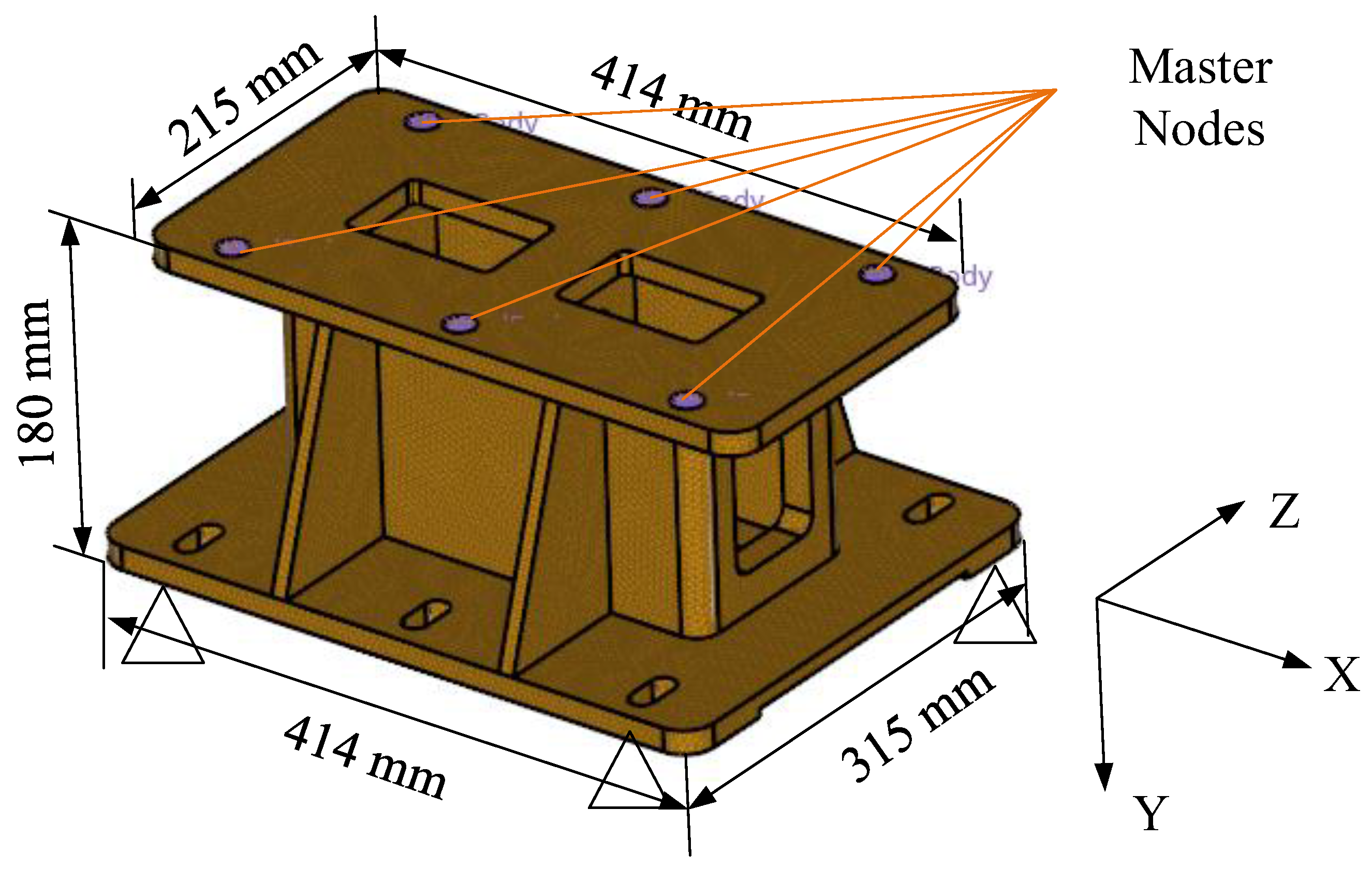
The foundation is 414 mm long, 180 mm high, 215 mm wide at the top, and 315 mm wide at the bottom. The material is AlMg1SiCu (ISO 209.1) with a density of 2700 kg/m3, Young’s modulus of 7 × 10¹⁰ Pa, Poisson’s ratio of 0.33, and a damping ratio of 2%. Figure 4 depicts the construction of a foundation FE model using a 4-node tetrahedral element. The element is 5 mm in dimension. About 61,000 nodes and 265,000 elements make up the FE model. Six bolt holes on the top surface are coupled to each center node, which are defined as the master nodes and are meshed with mass elements. The bottom area is fixed, and the first 500 modes are acquired. The mobility matrix Y has a dimension of 3636 since the model comprises six master nodes, each of which provides six-DOF.
The foundation’s impedance equation can be written as follows, such as the way for housing:
Z BS ( ω ) V BS ( ω ) = F BS ( ω )
where V BS is the velocity vector, F BS is the reaction force isolator to foundation.

2.5. Impedance Coupled Model

Impedance synthesis method [9] is used to develop the impedance equation of the entire system after dynamic models of all subsystems were built. By putting together impedance matrix components according to the node number, the coupled system’s impedance equation may be immediately determined. Assume there is no external force present at the subsystem interfaces. The coupled system’s impedance equation can be expressed in the form of:
Z V = F .
The following equation can be used to determine the velocity:
V ( ω ) = Z ( ω ) 1 F ( ω ) .

3. Layering Transfer Path Analyses

A vibration system can be generally split into three components: excitation source, transfer path, and receiver. Transfer path refers to all connection parts between the source and the receiving structure. By calculating the transmissibility and sorting the importance of each transfer path, the main path can be identified, which is very important for passive control and structural modification of vibration and noise reduction. With regard to a flexible supported gear system, the excitation source is the gear pair, and the receiver is the ship foundation.
The traditional TPA method takes force or velocity as variables to evaluate each transfer path. The VPF-based TPA can directly reflect the essence of vibration energy transferring. VPF is the average of instantaneous power over a period of time (for the minimum period of vibration for periodic vibration).
P = 1 T 0 T f ( t ) v ( t ) d t
where T denotes the period, f ( t ) denotes the external force, and v ( t ) denotes the velocity.
Assuming that both forces and velocities are harmonic, the VPF can be expressed in frequency domain:
P ( ω ) = 1 2 Re ( V H ( ω ) F ( ω ) )
where F ( ω ) and V ( ω ) are force and velocity in the frequency, respectively. Re ( * ) is the real part of *, and *H is the Hermitian transpose.
Since the force and velocity in Equation (24) are both complex, the VPF index can take into account both force and velocity, as well as their relative phases. The VPF index can be used to evaluate the vibration transferring process more effectively than force or velocity index. Moreover, the VPF as a scalar can consider the vibration of different directions synthetically.
The excitation power of the flexible supported gear system is generated by the dynamic TE of the gear. The excitation power of the gear can be expressed:
P GP = 1 2 Re ( V G P F e x t ) ,   i = 1 ,   2 ,     , n .
The vibratory power of the gears is entered into the foundation through the shaft, bearing, housing, and isolator, as is shown in Figure 5. Therefore, the vibration transferring process can be divided into shaft, bearing, housing, isolator, and foundation layer. The vibratory power transmitted by each layer is:
P i = 1 2 Re ( V i F i ) ,   i = 1 ,   2 ,     , n
where i denotes the shaft, bearing, housing, isolator, or foundation subsystem.
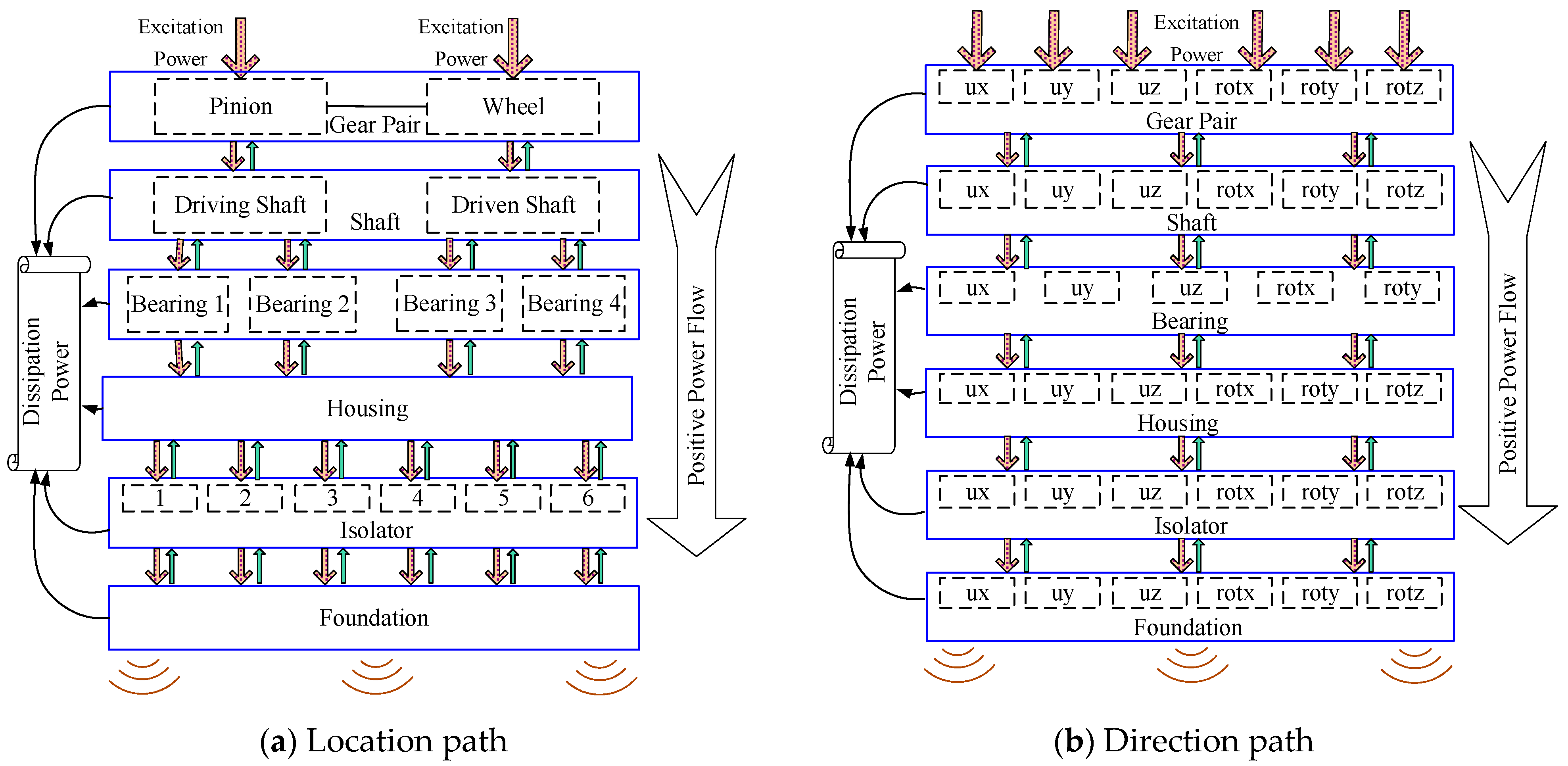
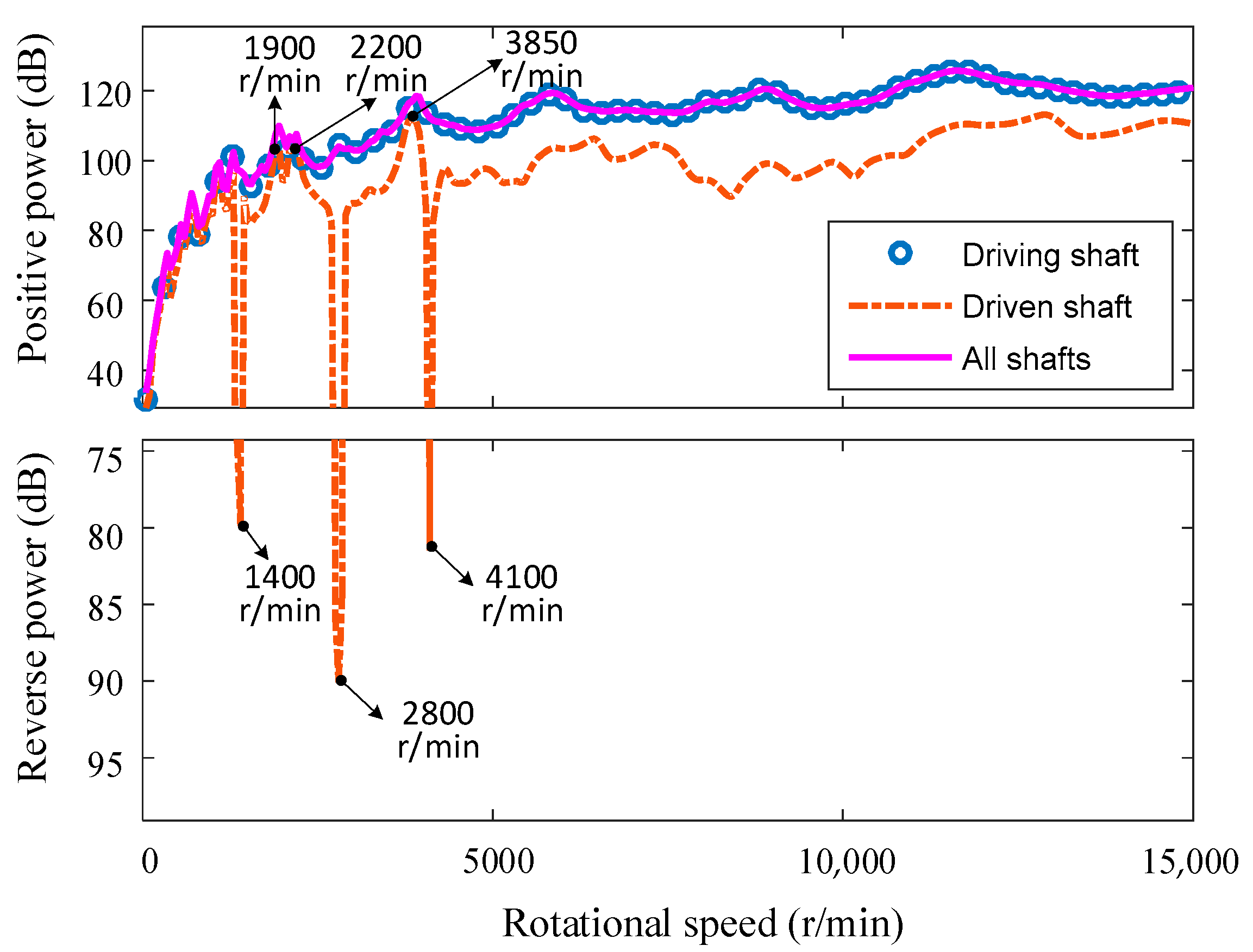
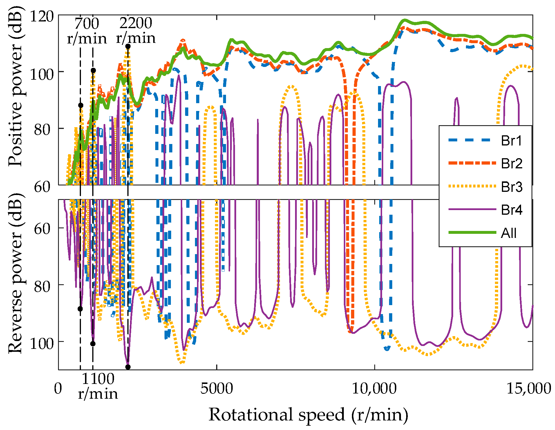
The transfer path of the gear system is the gear-shaft-bearing-housing-isolator-foundation in the whole. The transfer process of each layer can be divided into location transfer path and direction transfer path according to the location and direction of vibration transferring, as is described in 
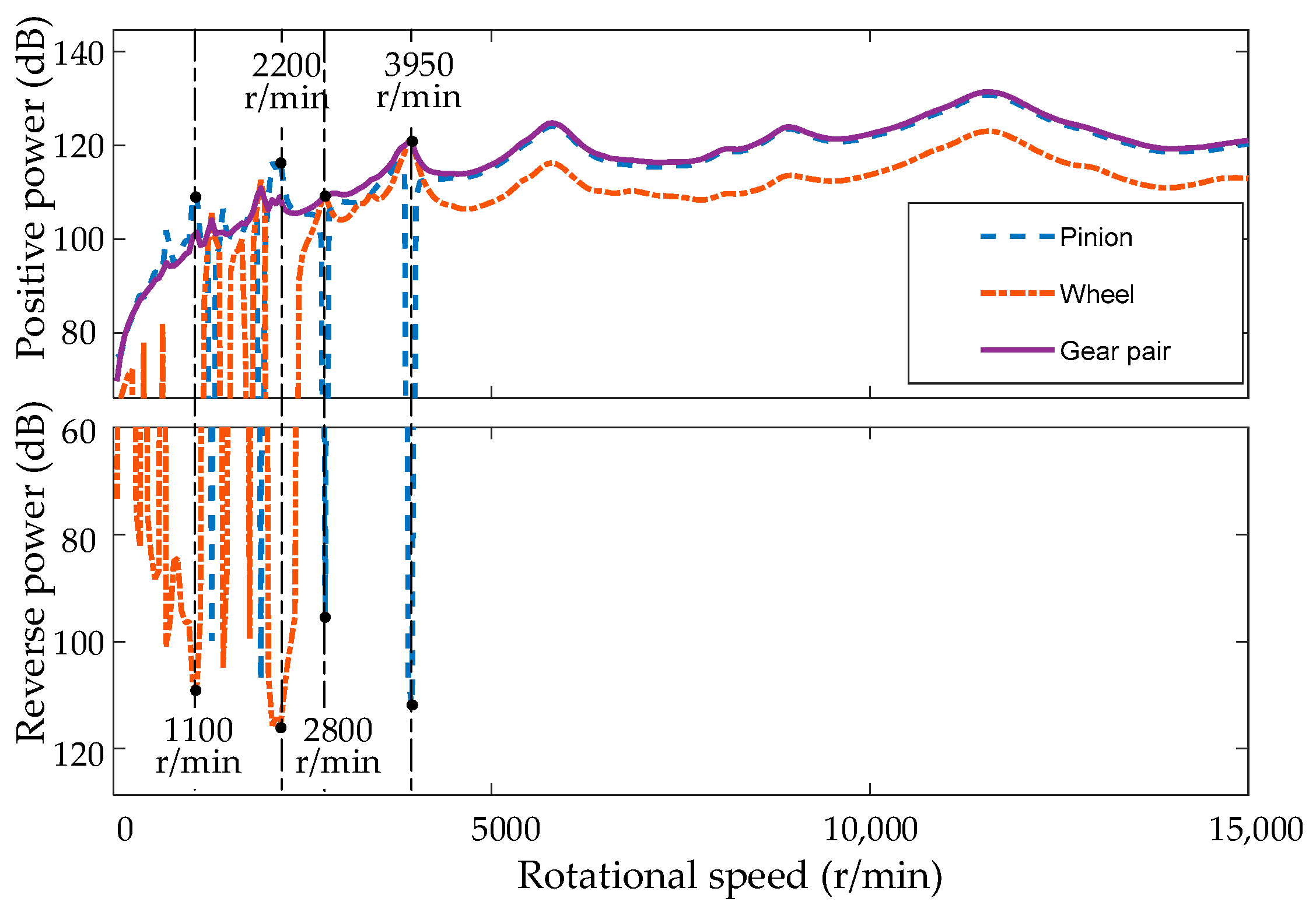
Figure 6. The layering location transfer path is shown in 
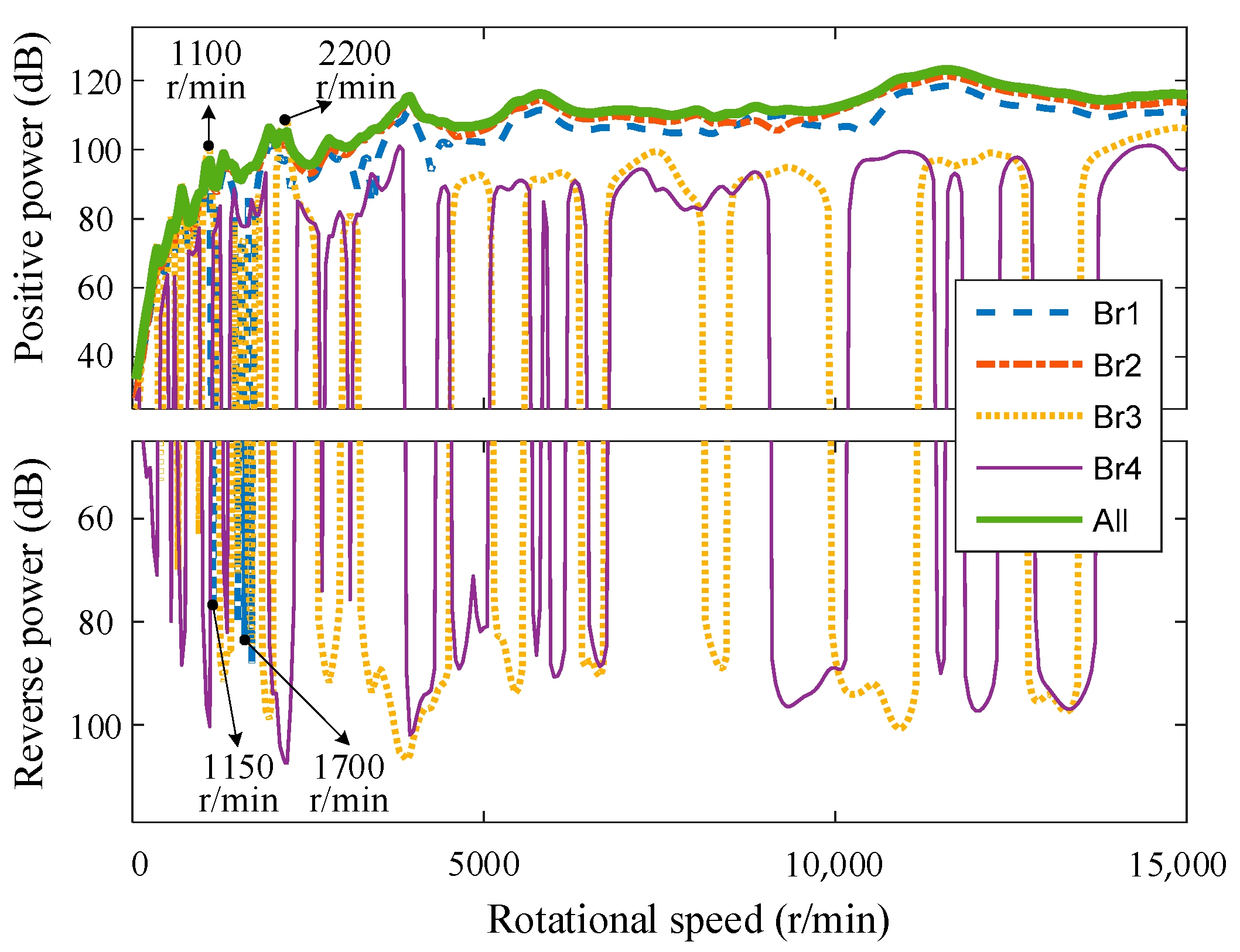
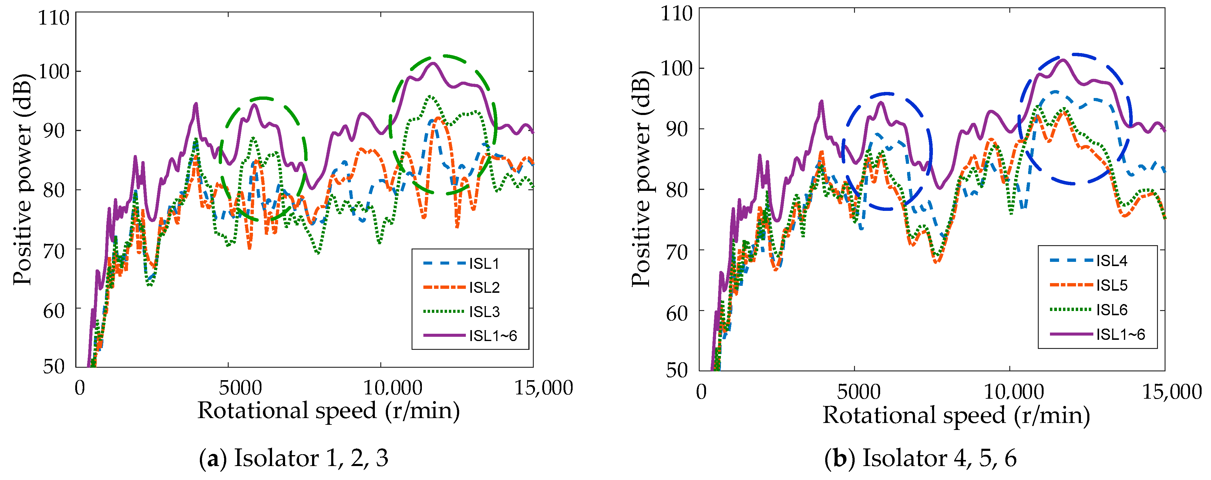
Figure 6a. The gear excitation power can be divided into pinion excitation power and wheel excitation power, which are transmitted to the driving shaft and the driven shaft, respectively, through the pinion and wheel; the driving shaft transfers the vibration to the bearings 1 and 2, and the driven shaft transfers to the bearings 3 and 4; each bearing transfers the vibration to the housing; and the housing transmits the vibration to the ship foundation through six vibration isolators. The layering direction transfer path is shown in 
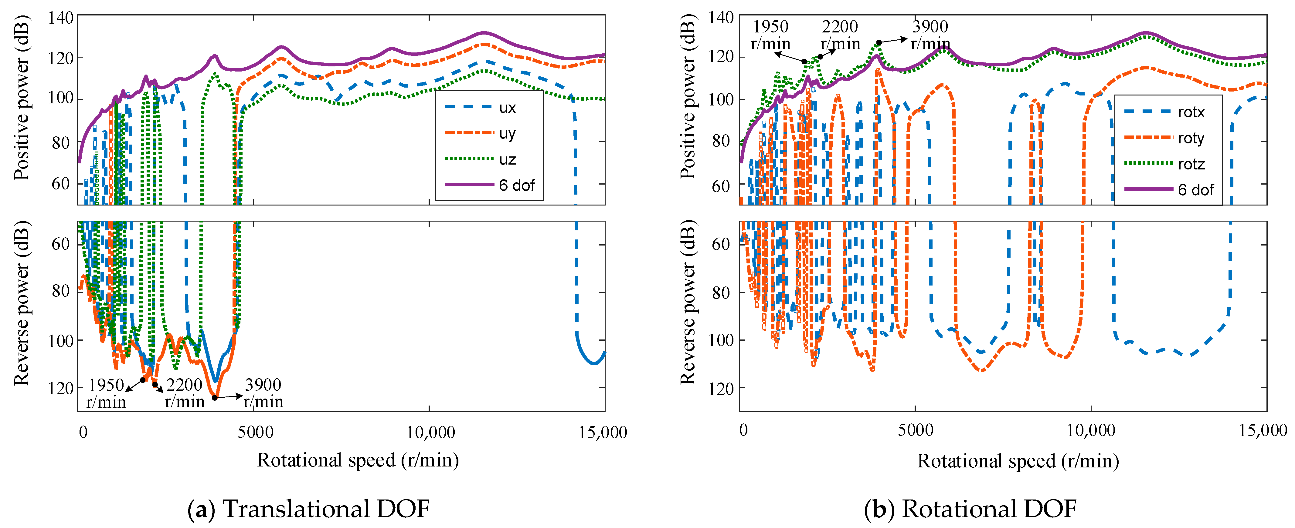
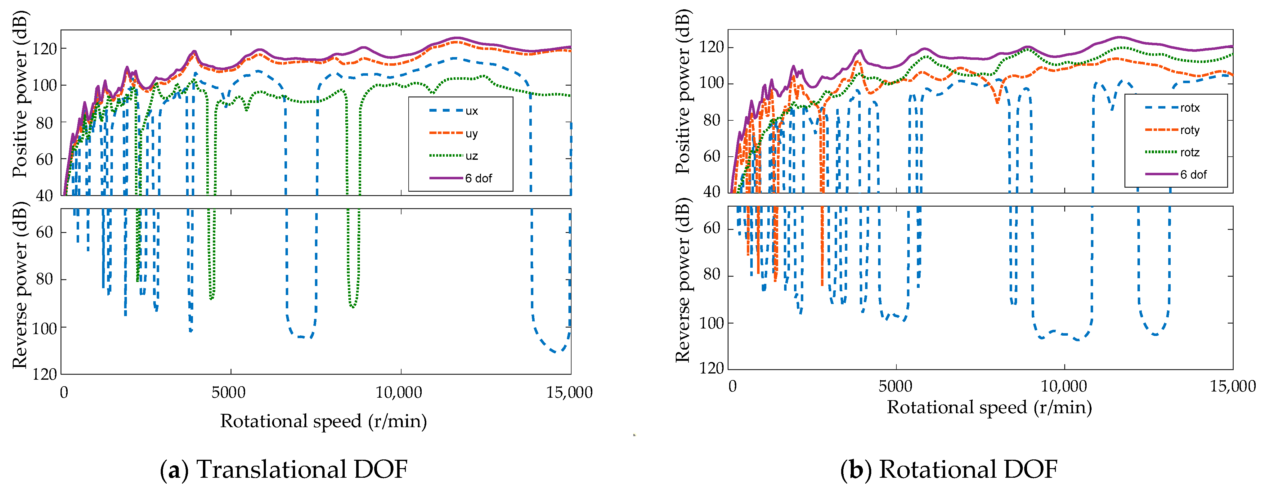
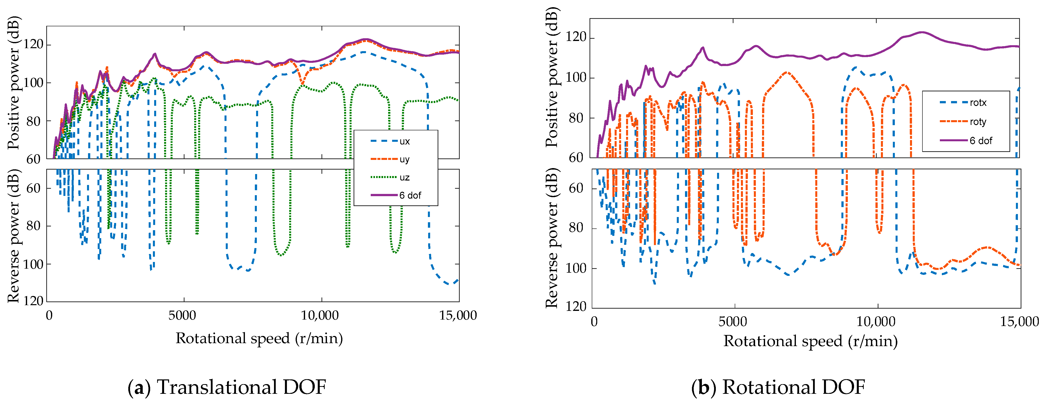
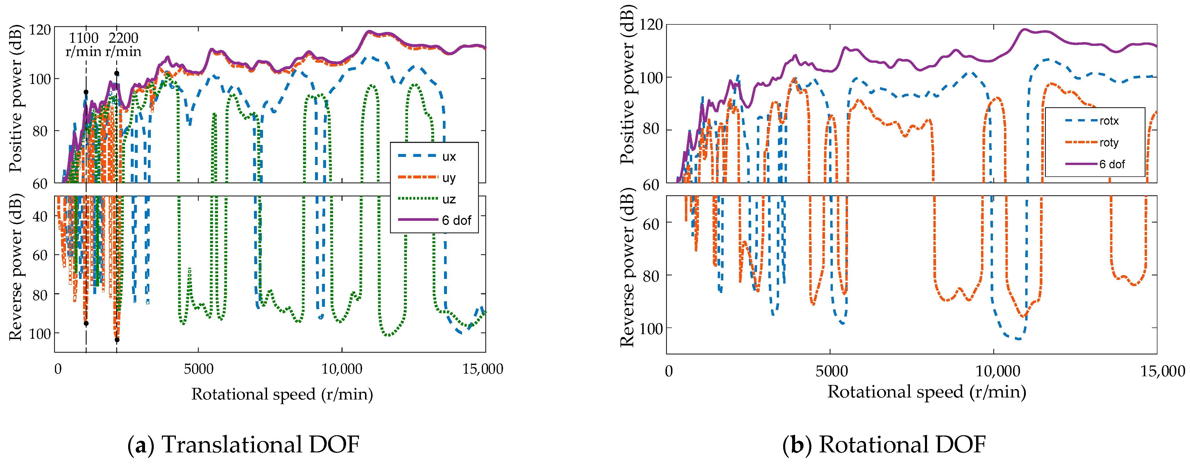
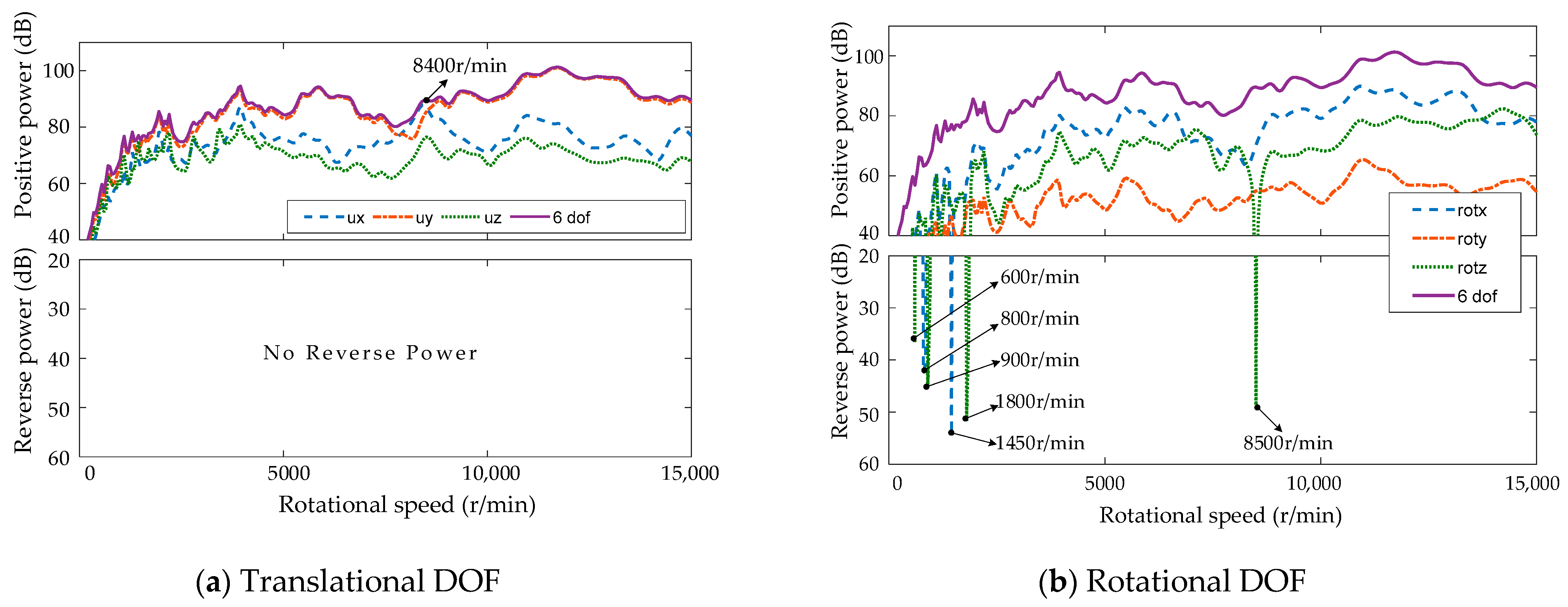
Figure 6b. Excitation power of gears includes six DOFs. The other subsystems include six DOFs, except bearing without torsional DOFs. The vibration energy transfer paths between subsystems can be regarded as virtual paths composed of six directions.
The vibratory power of each subsystem in location path is written as follows:
p i k = j = 1 J p i , j k , ( i = 1 : I )
where k denotes the subsystems, i is the number of location paths in each layer, and j denotes the direction.
The vibration power of each subsystem in direction path can be yielded:
p j k = i = 1 I p i , j k , ( j = 1 : J ) .

4. Results and Discussion

4.1. Excitation Power Flow of Gear Pair

Equation (25) is used to calculate the excitation power of gears with different location paths. The excitation power of the gear corresponding to the location path can be seen in Figure 7. It includes the excitation power of the pinion and wheel. Generally speaking, the excitation power of the gear pair is dominated by the pinion. The vibration power of the pinion above 5000 r/min is almost the same as that of the whole gear pair. The average excitation power of the pinion from 5000 r/min to 1500 r/min is only 0.7 dB lower than that of the gear pair. There exists reverse power flow in the system in some rotational speed below 5000 r/min; that is to say, the gear dissipates vibration power instead of acting as an excitation source. For example, there is obvious resonance around 1300 r/min, 1950 r/min, 2800 r/min, and 3950 r/min for the wheel, the directions of the excitation force and vibration velocity of pinion are opposite, resulting in reverse power flow for the pinion, which is 99.8 dB, 107.5 dB, 95.6 dB and 112.4 dB, respectively. There is obvious resonance near 700 r/min, 1100 r/min, 1450 r/min, and 2200 r/min for the pinion, and the amplitude is 101.9 dB, 109.9 dB, 106.5 dB, and 117.7 dB, respectively. However, there is obvious reverse power in the wheel at this time, which reduces the gear excitation power by 6.9 dB, 8.4 dB, 5.0 dB, and 8.7 dB, respectively. Although there will be reverse power flow in the pinion or wheel under specific conditions, the excitation power of the whole gear pair is positive power flow at all rotational speeds.
The phenomenon of reverse power flow was also mentioned in Ref. [33]. In a multi-path situation, the VPF along a given path could have some negative numbers.
Excitation power of each direction of the gear pair is shown in Figure 8a,b. The gear excitation power is mainly in torsion DOF rotz and vertical DOF uy (rotz DOF means the rotational DOF about z-axis, and uy DOF means the translational DOF along the y-axis). Between 5000 and 15,000 r/min, the power in rotz and uy directions is positive, and the average vibration power is 119.9 dB and 117.3 dB, respectively. The superposition of them is 121.9 dB, which is close to the total 122.1 dB. While, under 5000 r/min, almost all the uy directions are reverse power. The amplitude of the rotz directions is 118.5 dB, 120.3 dB, and 126.2 dB, respectively, near the resonance rotational speeds of 1950 r/min, 2200 r/min, and 3900 r/min. At this time, the uy direction has a large reverse power flow, with the amplitudes of 117.3 dB, 120.1 dB, and 124.6 dB, respectively, resulting in a reduction in the overall vibration power by 7.6 dB, 11.3 dB, and 5.6 dB, compared with the rotz direction. There is also obvious reverse power in the direction of uz at some rotating speed below 5000 r/min. There is reverse power in ux at low and high rotating speed, and there is obvious reverse power in rotx and roty at specific rotating speeds in the whole rotating speed range. The power flow of rotz and the whole system is constant positive power flow in the whole rotating speed range.

4.2. Gear Shaft Transmitted Power Flow

Equations (25) and (27) are used to calculate the transmitted power of gears to shafts in each location path. The transmitted power of the location path corresponding to the gear shaft is shown in Figure 9. It can be seen that most of the vibration power of the gears is transmitted to the driving shaft. The driven shaft receives certain vibration power only at some special resonance speed, such as 1900 r/min, 2200 r/min, and 3850 r/min. The average power of the driving shaft in the whole speed range is 111.3 dB, which is close to the total vibration power of 111.8 dB. Around 1400 r/min, 2800 r/min, and 4100 r/min, there is obvious reverse power in the driven shaft. The amplitude is 79.9 dB, 90.1 dB, and 81.5 dB, respectively. However, compared with the overall 96.9 dB, 104.0 dB, and 112.3 dB, the reverse power flow is too small and can be neglected.
The transmitted power of the corresponding gear shaft direction path is calculated according to Equations (25) and (28). Results are shown in Figure 10. The vibration power in the direction of uy and rotz is always positive, while the vibration power in the other direction has reverse direction at some specific speed. When the driving shaft’s rotating speed exceeds 5000 r/min, the vibration power is mainly in the direction of uy and rotz, while under 5000 r/min, ux, uy, uz, and roty, all contribute to a certain extent.

4.3. Shaft Bearing Transmitted Power Flow

Figure 11 shows the shaft bearing transmitted power corresponding to the location path. Over 5000 r/min in the high-speed range, the bearing 1 and 2 at the driving shaft receive the majority of the shaft’s vibration. The average vibration is 109.7 dB and 112.5 dB, respectively. The combined vibration of bearing 1 and 2 is 114.4 dB, which is close to the total power of 114.5 dB. Bearings 1, 2, and 3 all contribute greatly in the low-speed range below 5000 r/min. There are resonance peaks in the vibration of bearing 3 near 1100 r/min and 2200 r/min, and the amplitude is 4.2 dB and 3.8 dB larger than the total vibration. Bearing 4 has little contribution to vibration transferring in the whole speed range, which can be neglected. The total vibration power of all bearings is a constant positive in the whole speed range, and the vibration power received by bearing 2 in the whole speed range is also a positive power. Bearing 1 has reverse power near 1150 r/min, 1500 r/min, 1600 r/min, and 1700 r/min. Bearing 3 and 4 may have reverse power in the whole speed range.
Shaft bearing vibration power corresponding to the direction transfer path is shown in Figure 12. The vibration power is mainly transmitted to the uy DOF of bearings. The vibration of ux DOF is the largest near 9050 r/min ~ 9650 r/min. Ux and uy also contribute to a certain extent at low speed. The overall vibration power is always positive, and the vibration power in the direction of uy is also constantly positive. There is reverse power flow in other DOFs at a certain rotating speed. For instance at low speed, the direction of ux and rotx contribute most to the reverse power. On the whole, uz direction and roty direction have less influence on the vibration.

4.4. Bearing Housing Transmitted Power Flow

The bearing housing transmitted power corresponding to the location path is shown in Figure 13. At high speed, the vibration is mainly at bearing hole 1 and 2. The average vibration of bearing hole 1 and 2 corresponds to 5000 r/min~15,000 r/min is 99.2 dB and 103.7 dB, which is 109.9 dB in sum, close to the total vibration 109.8 dB. Bearing holes 3 and 4 also contribute a lot to vibration at low speed. For example, bearing hole 3 has obvious resonance near 700 r/min, 1100 r/min, and 2200 r/min. The peak values are 88.3 dB, 100.9 dB, and 108.7 dB, respectively, which are 9.2 dB, 11.3 dB, and 11.0 dB higher than the total vibration, respectively. There is obvious reverse power flow in bearing hole 4 at the corresponding speed, with the peak values of 88.7 dB, 101.2 dB, and 109.0 dB, respectively, which indicates that there is an obvious vibration suppression effect at bearing hole 4.
The vibration power of bearing housing corresponding to the direction path is shown in Figure 14. At high speed, the vibration is domain by uy and the vibration power in the uy direction is mainly positive. Ux only contributes to the vibration at some special rotational speed, while the other DOF contribute little to the vibration. At low speed, each DOF contributes to the vibration to a certain extent, and there are reverse power flows at some rotational speeds. There is resonance in the ux direction near 1100 r/min and 2200 r/min. Peak values are 94.6 dB and 102.5 dB, respectively, which are 5.0 dB and 4.8 dB higher than the total vibration power, while there is obvious reverse power in the uy direction, with the amplitudes of 96.1 dB and 103.9 dB, respectively. Relatively speaking, the contribution of roty DOF to vibration is small.

4.5. Housing Isolator Transmitted Power Flow

The transmitted power of the housing isolator corresponding to the location path is shown in Figure 15. The power flow direction of each isolator is always positive, and there is no reverse power flow. At low speed, the contribution of each isolator to vibration is almost the same, but at high speed, the contribution of each isolator is different at different rotational speeds. For example, between 5400 r/min and 6700 r/min, isolators 3 and 4 have the greatest contribution to vibration, while the contribution of other isolators is relatively small. Between 10,700 r/min and 13,450 r/min, isolator 3 and 4 also contribute significantly to vibration. Although isolators 1 and 2, 3 and 4, and 5 and 6 are symmetrically arranged, the vibration power of the corresponding isolator is different because the transmission system is asymmetrical.
The transmitted power corresponding to the direction path is shown in Figure 16. The direction of power in ux, uy, uz, and roty DOF are constantly positive. There are reverse power flows in rotx and rotz directions at very few rotational speeds. On the whole, the vibration power of the isolator is mainly in the vertical direction uy, and ux and uz also contribute to a certain extent at low speed. Ux has a resonance peak near 8400 r/min with an amplitude of 87.8 dB, which is 5.0 dB higher than the power of uy. Rotx has reverse power near 800 r/min and 1450 r/min, and rotz has reverse power near 600 r/min, 900 r/min, 1800 r/min, and 8500 r/min. However, these reverse powers are too small compared with the total power, and can be ignored.

4.6. Isolator Foundation Transmitted Power Flow

The transmitted power of the isolator foundation corresponding to the location path is shown in Figure 17. The total vibration power is 71.1 dB near 6500 r/min, and the vibration of isolator 4 is as high as 70.2 dB, which makes a significant contribution to the vibration. The total vibration near 8050 r/min is 59.0 dB, and the vibration of isolator 2 reaches 58.9 dB, which is the primary pathway for vibration transfer. The total vibration is 72.7 dB near 10,350 r/min, and the vibration of isolator 5 is as high as 71.7 dB, which is the main transfer path. At 13,050 r/min, the vibration at isolator 4 is only 0.8 dB lower than the total power, which contributes significantly to the vibration.
Reverse power flow may exist at each isolator connection. For example, the total vibration power near 2150 r/min is 61.1 dB, and the reverse power at isolator 5 is 57.5 dB. The total vibration is 60.3 dB near 2700 r/min, and the reverse power of isolator 6 is as high as 56.4 dB. The total vibration near 8050 r/min is 59.0 dB. At this time, the reverse power of isolator 1 is as high as 56.4 dB, which can compress the vibration greatly.
The transmission power corresponding to the direction path is shown in Figure 18. Generally speaking, the vertical direction uy domains the vibration of the foundation, but other DOF also contributes to a certain degree below 3800 r/min. For example, the overall vibration is 64.6 dB near 2200 r/min, the ux direction vibration is 63.4 dB, and the uy direction vibration is only 51.4 dB. The total vibration is 74.5 dB near 3450 r/min and 74.2 dB in the uz direction, while the vibration in the uy direction is only 54.1 dB at this time. At some rotational speed, such as 1100 r/min and 1700 r/min, there are even reverse power flows in the uy direction, with the amplitudes of 51.9 dB and 44.3 dB, respectively. At this time, the total vibration power is 55.3 dB and 65.3 dB, respectively. It shows that the uy direction has an obvious vibration suppression effect at 1100 r/min, but has little influence near 1700 r/min.

5. Conclusions

A coupled impedance model for a flexible supported gear system was developed in this study. According to the transfer process of gear vibration, the system was divided into gear, shaft, bearing, housing, isolator, and foundation layer. Based on the VPF index, the layering location TPA and the layering direction TPA were carried out in detail in a broad speed range according to the vibration transfer location and direction. From the simulation, the main conclusions are made:
  • Although vibration power of gears attenuates layer by layer in the transmission process from shaft, bearing, housing, and isolator to foundation, there will be reverse power flow in some location transfer paths and direction paths at a certain rotational speed;
  • The excitation power of the gear pair is mainly from pinion (above 75% for 85% cases), and the vibration transferred to shaft, bearing, and housing is mainly on the driving shaft side (above 85% for 86% cases), but the vibration of the driving shaft side is not prominent when transmitted to isolator and foundation;
  • The gear excitation power and the VPF transferred to the shaft are mainly domain by the torsional and vertical DOF (above 75% for 79% cases); the vertical vibration is the main vibration after being propagated to the bearing (above 70% for 78% cases), housing (above 65% for 79% cases), isolator (above 70% for 78% cases), and foundation (above 80% for 83% cases), and the vibration in other directions also has a certain degree of influence.

Author Contributions

Conceptualization, Y.R. and H.W.; methodology, Y.R.; software, X.S.; validation, Y.L. and W.L.; data curation, Y.L.; writing—original draft preparation, X.S.; writing—review and editing, W.L. All authors have read and agreed to the published version of the manuscript.

Funding

This research was funded by the Key Project of National Science Foundation of China, grant number 51535009; Shanxi excellent doctor’s work Award Fund, grant number 20202061; and Shanxi Basic Research Project, grant number 20210302124445.

Data Availability Statement

The data presented in this study are available on request from the corresponding author.

Conflicts of Interest

The authors declare no conflict of interest.

References

  1. Sun, M.; Chi, H.L.; Liu, Z.; Sun, Y.; Chen, H.; Shen, C. Classifying, predicting, and reducing strategies of the mesh excitations of gear whine noise: A survey. Shock Vib. 2020, 2020, 9834939. [Google Scholar] [CrossRef]
  2. Oktav, A.; Yılmaz, C.; Anlaş, G. Transfer path analysis: Current practice, trade-offs and consideration of damping. Mech. Syst. Signal. Process. 2017, 85, 760–772. [Google Scholar] [CrossRef]
  3. Qiao, Z.; Zhou, J.; Sun, W.; Zhang, X. A coupling dynamics analysis method for two-stage spur gear under multisource time-varying excitation. Shock. Vib. 2019, 2019, 7350701. [Google Scholar] [CrossRef]
  4. Han, J.; Liu, Y.; Yu, S.; Zhao, S.; Ma, H. Acoustic-vibration analysis of the gear-bearing-housing coupled system. Appl. Acoust. 2021, 178, 108024. [Google Scholar] [CrossRef]
  5. Zhou, J.; Liu, G.; Wu, L.-Y. Vibration analysis of marine planetary reducer with elastic support. J. Harbin Inst. Technol. 2012, 44, 97–101. (In Chinese) [Google Scholar]
  6. Tao, J.S.; Liu, G.R.; Lam, K.Y. Design optimization of marine engine-mount system. J. Sound Vib. 2000, 235, 477–494. [Google Scholar] [CrossRef]
  7. Huang, H.; Fu, S.; Luo, S. Analysis of the Influence of Transmission Housing Elasticity on the Vibration Characteristics of Gear Shafting under Coupling Effect. Shock Vib. 2021, 2021, 9623119. [Google Scholar] [CrossRef]
  8. Zhu, H.; Chen, W.; Zhu, R.; Gao, J.; Liao, M. Modelling and dynamic analysis of the spiral bevel gear-shaft-bearing-gearbox coupling system. Math. Probl. Eng. 2019, 2019, 9065215. [Google Scholar] [CrossRef]
  9. Ren, Y.; Chang, S.; Liu, G.; Wu, L.; Lim, T.C. Impedance synthesis based vibration analysis of geared transmission system. Shock Vib. 2017, 2017, 4846532. [Google Scholar] [CrossRef]
  10. Kong, X.; Tang, J.; Siyu, C.; Hu, Z. Effects of gearbox housing flexibility on dynamic characteristics of gear transmission system. J. Vib. Control 2021, 27, 2097–2108. [Google Scholar] [CrossRef]
  11. Xu, X.; Tao, Y.; Liao, C.; Dong, S.; Chen, R. Dynamic simulation of wind turbine planetary gear systems with gearbox body flexibility. Stroj. Vestn.-J. Mech. Eng. 2016, 62, 678–684. [Google Scholar] [CrossRef]
  12. Guo, Y.; Eritenel, T.; Ericson, T.M.; Parker, R.G. Vibro-acoustic propagation of gear dynamics in a gear-bearing-housing system. J. Sound Vib. 2014, 333, 5762–5785. [Google Scholar] [CrossRef]
  13. Xiao, H.; Zhou, X.; Liu, J.; Shao, Y. Vibration transmission and energy dissipation through the gear-shaft-bearing-housing system subjected to impulse force on gear. Measurement 2017, 102, 64–79. [Google Scholar] [CrossRef]
  14. Vanhollebeke, F.; Peeters, J.; Vandepitte, D.; Desmet, W. Using transfer path analysis to assess the influence of bearings on structural vibrations of a wind turbine gearbox. Wind Energy 2015, 18, 797–810. [Google Scholar] [CrossRef]
  15. Xu, H.; Qin, D.; Liu, C.; Yi, Y.; Jia, H. Dynamic modeling of multistage gearbox and analysis method of resonance danger path. IEEE Access 2019, 7, 154796–154807. [Google Scholar] [CrossRef]
  16. Nie, Y.; Li, F.; Wang, L.; Li, J.; Sun, M.; Wang, M.; Li, J. A mathematical model of vibration signal for multistage wind turbine gearboxes with transmission path effect analysis. Mech. Mach. Theory 2022, 167, 104428. [Google Scholar] [CrossRef]
  17. Liu, X.; Thompson, D.; Squicciarini, G.; Rissmann, M.; Bouvet, P.; Xie, G.; Martinez-Casas, J.; Carballeira, J.; Arteaga, I.L.; Garralaga, M.A.; et al. Measurements and modelling of dynamic stiffness of a railway vehicle primary suspension element and its use in a structure-borne noise transmission model. Appl. Acoust. 2021, 182, 108232. [Google Scholar] [CrossRef]
  18. Baduidana, M.; Kenfack-Jiotsa, A. Optimal design of inerter-based isolators minimizing the compliance and mobility transfer function versus harmonic and random ground acceleration excitation. J. Vib. Control 2021, 27, 1297–1310. [Google Scholar] [CrossRef]
  19. Li, M.; Liu, Q.; Dai, G.; Chen, W.; Zhu, R. Vibration Transfer Path Analysis of Double-Layer Box for Marine Reducer. J. Vib. Eng. Technol. 2021, 9, 1077–1089. [Google Scholar] [CrossRef]
  20. Dong, Z.; Yang, J.; Zhu, C.; Chronopoulos, D.; Li, T. Energy flow and performance evaluation of inerter-based vibration isolators mounted on finite and infinite flexible foundation structures. Adv. Mech. Eng. 2022, 14, 16878140211070461. [Google Scholar] [CrossRef]
  21. Yang, J.; Xiong, Y.P.; Xing, J.T. Vibration power flow and force transmission behaviour of a nonlinear isolator mounted on a nonlinear base. Int. J. Mech. Sci. 2016, 115, 238–252. [Google Scholar] [CrossRef]
  22. Yang, B.; Hu, Y.; Fang, H.; Song, C. Research on arrangement scheme of magnetic suspension isolator for multi-degree freedom vibration isolation system. J. Ind. Inf. Integr. 2017, 6, 47–55. [Google Scholar] [CrossRef]
  23. Yang, Y.; Pan, G.; Yin, S.; Yuan, Y. Vibration transmission path analysis of underwater vehicle power plant based on TPA power flow. Proc. Inst. Mech. Eng. Part M J. Eng. Marit. Environ. 2022, 236, 150–159. [Google Scholar] [CrossRef]
  24. Lee, S.K. Identification of a vibration transmission path in a vehicle by measuring vibrational power flow. Proc. Inst. Mech. Eng. Part D J. Automob. Eng. 2004, 218, 167–175. [Google Scholar] [CrossRef]
  25. Yang, J.; Yang, L.; Zhu, R.; Chen, W.; Li, M. Effects of vibration isolator on compound planetary gear train with marine twin-layer gearbox case: A dynamic load analysis. J. Vib. Eng. Technol. 2021, 9, 767–780. [Google Scholar] [CrossRef]
  26. Luan, J.; Zhang, J.Z.; Wan, X.B. Study on support stiffness optimization of the vibration-isolating double layer box for planetary gear reducer. J. Eng. Therm. Energy Power 2019, 34, 103–112. (In Chinese) [Google Scholar]
  27. Ren, Y.; Chang, S.; Liu, G.; Wu, L.; Wang, H. Vibratory Power Flow analysis of a gear-housing-foundation coupled system. Shock Vib. 2018, 2018, 5974759. [Google Scholar] [CrossRef]
  28. Ren, Y.F.; Chang, S.; Liu, G. Study on low vibration isolator arrangement of marine gearboxes based on an impedance model. Trans. Can. Soc. Mech. Eng. 2020, 44, 580–591. [Google Scholar] [CrossRef]
  29. Harris, S.L. Dynamic loads on the teeth of spur gears. Proc. Inst. Mech. Eng. 1958, 172, 87–112. [Google Scholar] [CrossRef]
  30. Lim, T.C.; Singh, R. Vibration transmission through rolling element bearings, part I: Bearing stiffness formulation. J. Sound Vib. 1990, 139, 179–199. [Google Scholar] [CrossRef]
  31. Golub, G.H.; Underwood, R. The block Lanczos method for computing eigenvalues. In Mathematical Software; Rice, J.R., Ed.; Academic Press: Cambridge, MA, USA, 1977; pp. 361–377. [Google Scholar]
  32. Lanczos, C. An iteration method for the solution of the eigenvalue problem of linear differential and integral operators. J. Res. Natl. Bur. Stand. 1950, 45, 255–282. [Google Scholar] [CrossRef]
  33. Inoue, A.; Kim, S.; Singh, R. Comparative evaluation of structure-borne noise transfer paths in a laboratory experiment. Noise Control Eng. J. 2006, 54, 382–395. [Google Scholar] [CrossRef]
Figure 1. Gear isolation coupled system.
Processes 11 01233 g001
Figure 2. Geared transmission system.
Processes 11 01233 g002
Figure 3. The housing FE model.
Processes 11 01233 g003
Figure 4. The foundation FE model.
Processes 11 01233 g004
Figure 5. Vibration transfer process.
Processes 11 01233 g005
Figure 6. Layering transfer path.
Processes 11 01233 g006
Figure 7. Excitation power flow of gear pair—location path.
Processes 11 01233 g007
Figure 8. Excitation power flow of gear pair—direction path.
Processes 11 01233 g008
Figure 9. Gear shaft transmitted power flow—location path.
Processes 11 01233 g009
Figure 10. Gear shaft transmitted power flow—direction path.
Processes 11 01233 g010
Figure 11. Shaft bearing transmitted power—location path.
Processes 11 01233 g011
Figure 12. Shaft bearing transmitted power—direction path.
Processes 11 01233 g012
Figure 13. Bearing housing transmitted power—location path.
Processes 11 01233 g013
Figure 14. Bearing housing transmitted power flow—direction path.
Processes 11 01233 g014
Figure 15. Housing isolator transmitted power—location path.
Processes 11 01233 g015
Figure 16. Housing isolator transmitted power—direction path.
Processes 11 01233 g016
Figure 17. Isolator foundation transmitted power—location path.
Processes 11 01233 g017
Figure 18. Isolator foundation transmitted power—direction path.
Processes 11 01233 g018
Disclaimer/Publisher’s Note: The statements, opinions and data contained in all publications are solely those of the individual author(s) and contributor(s) and not of MDPI and/or the editor(s). MDPI and/or the editor(s) disclaim responsibility for any injury to people or property resulting from any ideas, methods, instructions or products referred to in the content.

