
Machining of Custom-450 Grade Stainless Steel Using TiAlSiN-Coated Tungsten Carbide Tool Inserts


1
Department of Mechanical Engineering, Vel Tech Rangarajan Dr. Sagunthala R&D Institute of Science and Technology, Avadi 600 062, India
2
Department of Machining, Assembly and Engineering Metrology, Faculty of Mechanical Engineering, VSB-Technical University of Ostrava, 17. Listopadu 2172/15, 708 00 Ostrava, Czech Republic
3
Department of R&D, Bond Marine Consultancy, London EC1V 2NX, UK
*
Authors to whom correspondence should be addressed.
Processes 2023, 11(4), 1037; https://doi.org/10.3390/pr11041037
Submission received: 16 February 2023
/
Revised: 14 March 2023
/
Accepted: 22 March 2023
/
Published: 29 March 2023
(This article belongs to the Section Manufacturing Processes and Systems)
Abstract
:Turning operations using single-point cutting tools have been one of the earliest and most used methods for cutting metal. It has been widely studied for cutting forces and workpiece surface roughness to affect turning operations. When cutting metal, the cutting tool needs to be tougher than the workpiece so it can resist high temperatures and wear while the operation is conducted. The mechanical qualities of martensitic stainless steel (MSS) grade Custom-450 can be significantly enhanced by heat treatment processes, which also provide it with an outstanding corrosion-resistance material. It has excellent resistance to rusting and pitting in a saltwater environment. Nuclear power reactors, screens for the pulp and paper sector, chemical processing, and power generation are just a few industries that require Custom-450 grade steel. To increase the workpiece’s machinability, dimensional precision, and appealing surface finish, the cutting tool industries have recently demonstrated a great interest in developing hard coatings and cutting tool technology. In the present study, Custom-450 grade stainless steel was used for machining (turning operation), using a tungsten carbide tool insert coated with TiAlSiN using the physical vapor deposition (PVD) method. The machining parameters such as the speed, feed, and depth of cut (DOC) were varied Surface roughness and various forces (cutting force, thrust force, and feed force) were evaluated by varying these three parameters. The depth of cut is the main factor affecting the surface roughness. More plastic deformation may lead to a rougher surface as a result. The tungsten carbide insert wear decreased with an increase in the cutting speed. An increase in feed considerably accelerates the tool wear of the inserts. As the depth of cut grows, the likelihood of tool wear also increases. The depth of cut, however, has a greater effect on tool wear than anything else. Therefore, the surface roughness in the sample is reduced as the cutting speed is increased.
1. Introduction
One of the earliest and most common techniques for cutting metal has been turning operations utilizing single-point cutting tools [1]. With shorter lead times, it has even taken the position of grinding in some applications without sacrificing the surface quality. Cutting forces and workpiece surface roughness are two crucial factors that are extensively researched in turning operations [2]. When examining the process capabilities of any machining operation, process parameter optimization is quite important. In the turning operation, excess material is removed by rotating the workpiece against a cutting tool. It is a well-known fact that only cylindrical workpieces can be machined during this operation [3]. During the metal-cutting operations, the cutting tool should be harder than the workpiece, which can withstand high temperatures and wear at the time of the operation [4,5]. Researching cutting forces in turning operations is significant, since they have an impact on a variety of variables, including the surface accuracy, tool wear, tool breakage, cutting temperature, and self-excited and forced vibrations, etc. [6].
The martensitic stainless steel (MSS) grade Custom-450 has excellent corrosion-resistance and heat treatment techniques, which can greatly improve its mechanical properties. In a saltwater environment, it has great resistance to rusting and pitting. Custom-450 grade steel is used in various industries such as nuclear power plants, screens for the pulp and paper industry, chemical processing, and power generation. This alloy is easily produced by various cold-rolled methods despite having a yield strength of more than 100 KSI (689 MPa) in the annealed condition. A single-step aging process results in increased mechanical properties such as strength, ductility, and toughness. Custom-450 has been used where austenitic stainless steel such as 304 cannot withstand enough of the strength and corrosion properties. Custom-450 MSS has a corrosion resistance similar to alloy 304 stainless steel and a substantially better yield strength. In some studies, it has been observed that the strength of Custom-450 MSS has the capability to replace ferritic grade alloy (410 stainless steel), where alloy 410 had insufficient corrosion-resistance abilities [7,8].
Yadav et al. [9] studied the relationship between the changes in hardness brought about on the material surface as a result of the turning operation with regard to several machining parameters, including the spindle speed, feed, and depth of cut. The experiments were planned using the Taguchi method, and in this work, EN 8 metal was chosen as the workpiece, coated carbide was chosen as the tool material, and the Rockwell scale was utilized to test hardness after turning.
The weight of Custom-450 stainless steel is a little lesser when compared to other ferrous materials alloys; due to its lightweight properties, it is used in aircraft applications such as fighter jet manufacturing processes. It is also used in medical instrument manufacturing, due to its high corrosion resistance and completely recyclable properties.
Inserts are cutting tips that are neither brazed nor welded to the tool body, but are instead, removable from it. They are typically indexable, allowing for swapping, rotation, and reversal without changing the general geometry of the tool. (effective diameter, tool length offset, etc.) [10]. This saves time in the manufacturing process by enabling the periodic presentation of fresh cutting edges without the need for tool grinding, setup modifications, or the entry of new values into a CNC programmer [11]. Tool inserts not only increase the output quality but they also help keep manufacturing costs down. Tool inserts for geometry includes things such as the nose radius, approach angle, rake angle, angle of inclination, clearance angle, and so on. The cutting tool industries have recently shown a strong interest in creating hard coatings and innovative cutting tool technologies to improve the workpiece’s machinability and dimensional accuracy with a nice surface finish [12]. In addition to creating new tools, creating new coatings for the existing tools resulted in the creation of new inventive tools for the aforementioned use. There are various methods for the deposition of coatings over tools. Such coatings are physical vapor deposition (PVD) and chemical vapor deposition [13]. Extensively available coatings are TiN, TiC, TiAlN, Al2O3, AlCrN, TiCN, AlTiN, and TiO2 [14]. These coatings not only improve machining outputs such as surface finish, force generation at the machining zone, machining accuracy, material removal rate, etc., but they also have advantages such as high melting points, better wear resistance, high thermal stability, high toughness, frictional resistance, high strengths, and lower heat generation, even under difficult machining conditions [15].
A single-layered AlCrN-based coating on WC inserts made using the physical vapor deposition method has been studied by Lakshmanan et al. On a carbide insert, characteristics such as microhardness, coating thickness, surface shape, and elemental composition were noted. Under conventional and cryogenic coolant (LN2) conditions, turning operations on the Ti-6Al-4V alloy were carried out with coated carbide (AlCrN-cc) and uncoated carbide (UCC) inserts [16]. An experimental parameter with a varying feed (f), depth of cut (d), and cutting speed was used to measure the 2D roughness value (Ra) and turning forces (Vc). In order to improve the mechanical properties of hard coatings for the metal-cutting industry, Kainz et al. conducted research on the use of a multilayered coating architecture based on two alternating hard materials [17]. In this study, the mechanical behaviors of the TiN/TiBN multilayer coatings created using chemical vapor deposition (CVD) were investigated with their microstructure and compared with the corresponding single layers. At an industrial-scale thermal CVD machine, multilayers with various bilayer periods (1400, 800, 300, and 200 nm) were created by varying up the feed gas. The primary issues with titanium machining, with regard to tool wear and the causes behind tool failure, were evaluated by Ezugwu et al. It was discovered that ceramics and CVD-coated carbides have not replaced cemented carbides because of their reactivity with titanium, their relatively low fracture toughness, and the poor thermal conductivity of most ceramics. Instead, straight tungsten carbide/Cobalt (WC/Co) cutting tools have maintained their superiority in nearly all machining processes of titanium alloys [18]. Emel et al. demonstrated that during milling with varying nose radii, adhesion, abrasion, chipping, and fracture were the primary tool failure mechanisms and modes. With the exception of up milling at 100 m/min, the cutting pressures decreased with an increase in the nose radius, irrespective of the cutting speed and milling direction [19]. According to the experimental findings, roughness decreased as the nose radius and speed increased. Surface roughness and the resulting forces were discovered to be less severe during up-milling than during down-milling. It was shown that the increase in the nose radius boosted the chip’s morphology’s edge serration. The mechanical and microstructural characteristics of the materials are altered at cryogenic temperatures. Alborz et al. carried out a study on cryogenic milling. In end milling the Ti-6Al-4V titanium alloy, the effects of cryogenic chilling on the surface’s integrity are contrasted with those of traditional dry and flood cooling. Several combinations of cutting settings were used in a series of machining trials. Each sample’s subsurface microhardness was assessed, along with surface roughness and microscopic surface integrity [20].
In order to identify the essential geometrical characteristics and grades of carbide inserts for turning nickel-based alloys, Fernandez-Valdivielso et al. suggested a new testing procedure [21]. Gandarias et al. discussed the controversy surrounding the cryogenic treatment of steels. Though cryogenic treatment has been shown to be effective in some cases, such as in high-speed steel (HSS), its effectiveness in carbide inserts is still debated [22]. Peteira et al. discussed the cryogenic treatment of AP23 steel using carbon dioxide. They inferred that the tool life increased by 12% and the surface roughness decreased after subjecting the tool to cryogenic treatment [23]. Polvorosa et al. presented and summarized the results of face-turning testing for flank and notch wear, using cooling at 6 bar and 80 bar. They inferred that short, large grain alloy structures lead to higher notch wear [24]. Amigo et al. predicted the cutting force and tool wear during the high-speed turning of the Nimonic super alloy [25]. The cutting force and tool wear during the high-speed turning of the Nimonic super alloy were anticipated by Amigo et al. The wear prediction model obtained relative errors of less than 5% for cutting speeds under 100 m/min and less than 14% for higher speeds, demonstrating a good agreement with the experimental results. By increasing the tool life to three times, the benefit of decreasing the side cutting edge angle on the tool life (from 90° to 30°) was also shown (from 8 to 24 min). In their research, Zhang et al. talked about the use of an in-process stochastic tool wear diagnosis for better micromilling cutting force modelling. To forecast the values of stochastic tool wear, they proposed an enhanced integrated estimate technique based on the long short-term memory (LSTM) network and particle filter (PF) algorithm. They deduced that the supply and durability of microcutting tools had improved, and that the prediction accuracy could also be boosted by 3.4% in comparison to that without taking the impact of tool wear into account [26].
From the above literature, we can conclude that there is literature that is related to machining under normal conditions. However, the machining of the sample with the insert coated with TiAlSiN under cryogenic conditions is scanty. This study attempts to determine the machining parameters of the monolayered tungsten carbide inserts during the turning operations of Custom-grade 450 stainless steel. The machining parameters such as feed, cutting speed, and depth of cut were determined. Additionally, surface roughness was measured for all the samples. The tools were subjected to cryogenic coating for 36 h, respectively.
2. Materials and Methods
The present study uses Custom-450 grade stainless steel of dimensions 510 mm (length) × 89 mm (diameter). The sample was procured from the market in as rolled condition without annealing. The chemical composition of the sample performed by optical emission spectroscopy is given as carbon: 0.02, manganese: 0.50, phosphorus: 0.01, silicon: 0.5, chromium: 15.00, nickel: 6.00, molybdenum: 0.70, copper: 1.25, and iron: balance. A tungsten carbide tool with TiAlSiN coating insert is used for the turning operation in the lathe machine. The Tungsten carbide inserts are coated with monolayered TiAlSiN under PVD conditions.
A coatings sample was created using DC magnetron sputtering in Cemecon’s (Würselen, Germany) industrial unit CC800/9. Four unbalanced planar magnetron sources are part of the deposition system, and they are positioned at the corners of a chamber. Two TiAl targets and two TiSi targets, respectively, were active during the preparation of the single layer TiAlN and TiSiN coatings. The 88 mm × 500 mm segmental targets of TiAl and TiSi were used to create the nanostructured TiAlSiN coating. The substrates were cleaned with acetone and ultrasonic before deposition, then rinsed in deionized water and dried with hot air. A 45 min mid-frequency ion etching experiment using a 650 V turntable and mixed argon and krypton gas at a flow rates of 180 mL/min and 50 mL/min was carried out at a pressure of 0.35 Pa. To keep the overall operating pressure at 660 mPa throughout the deposition operations, the argon, krypton, and nitrogen gas fluxes were all kept constant. The substrates were subjected to an imposed DC bias of 90 V. The rotation speed of the substrate holder was adjusted to 3 rpm for the deposition of the nanolayered TiAlSiN coating.
The tool was soaked in liquid nitrogen for 36 h prior to the machining of the sample for increasing strength and machinability characteristics. Cryogenic treatment helps in terms of a longer life of tool insert, less damage due to wear and tear, improved ability to withstand thermal pressures, reduced coefficient of friction, improved hardness, and easier machining.
This study considered three different control factors with three different levels, as shown in Table 1. As shown in Table 2, a full factorial design (FFD) of experiments is considered for this study. A FFD has several advantages, such as more efficiency as compared to one factor at a time experiments [27,28]. The experiments were carried out on center lathe (cone and pully medium duty lathe machine–VMS-255) with variable speed and feed drive with an attached tool dynamometer setup for force measurement analysis. The dynamometer used for measurements of forces was Ramson IL15. For each experiment, a fresh cutting edge was used. Each machining operation was carried out for one minute. For each experiment, the feed force (Fx), thrust force (Fy), and cutting force (Fz) are tabulated. All the experiments were performed under dry conditions (without coolant). The surface roughness value for each machined surface is found precisely using a probe-type surface roughness tester. The control factors were cutting speed (Vc), feed (f), and depth of cut (DOC). Table 2 shows the readings of all the parameters. For microstructural examination, a scanning electron microscopy (SEM) was performed using Tescan Vega-3w attached with energy dispersive spectroscopy (EDS). The EDS was used for providing the compositional analysis of the tool sample and workpiece sample/base material.
3. Results and Discussions
3.1. SEM and EDS Analysis
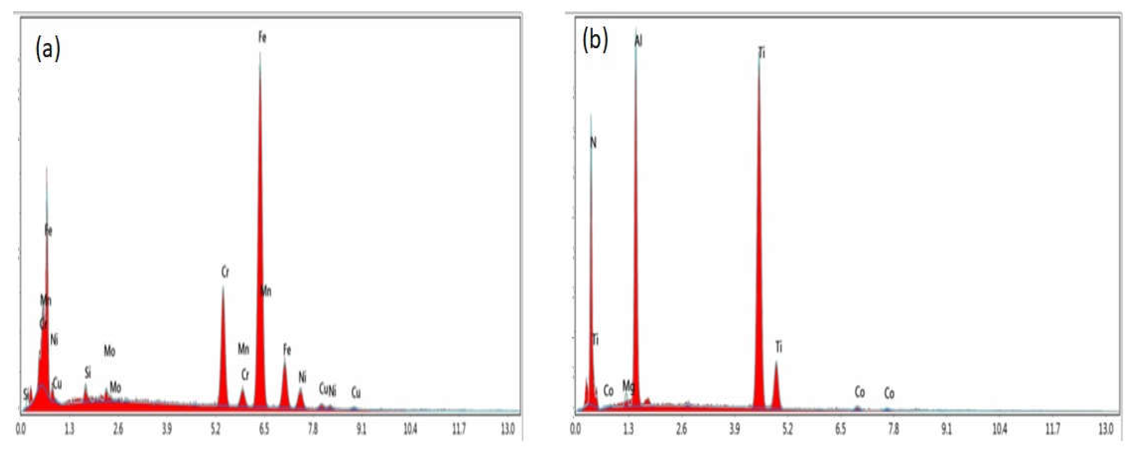
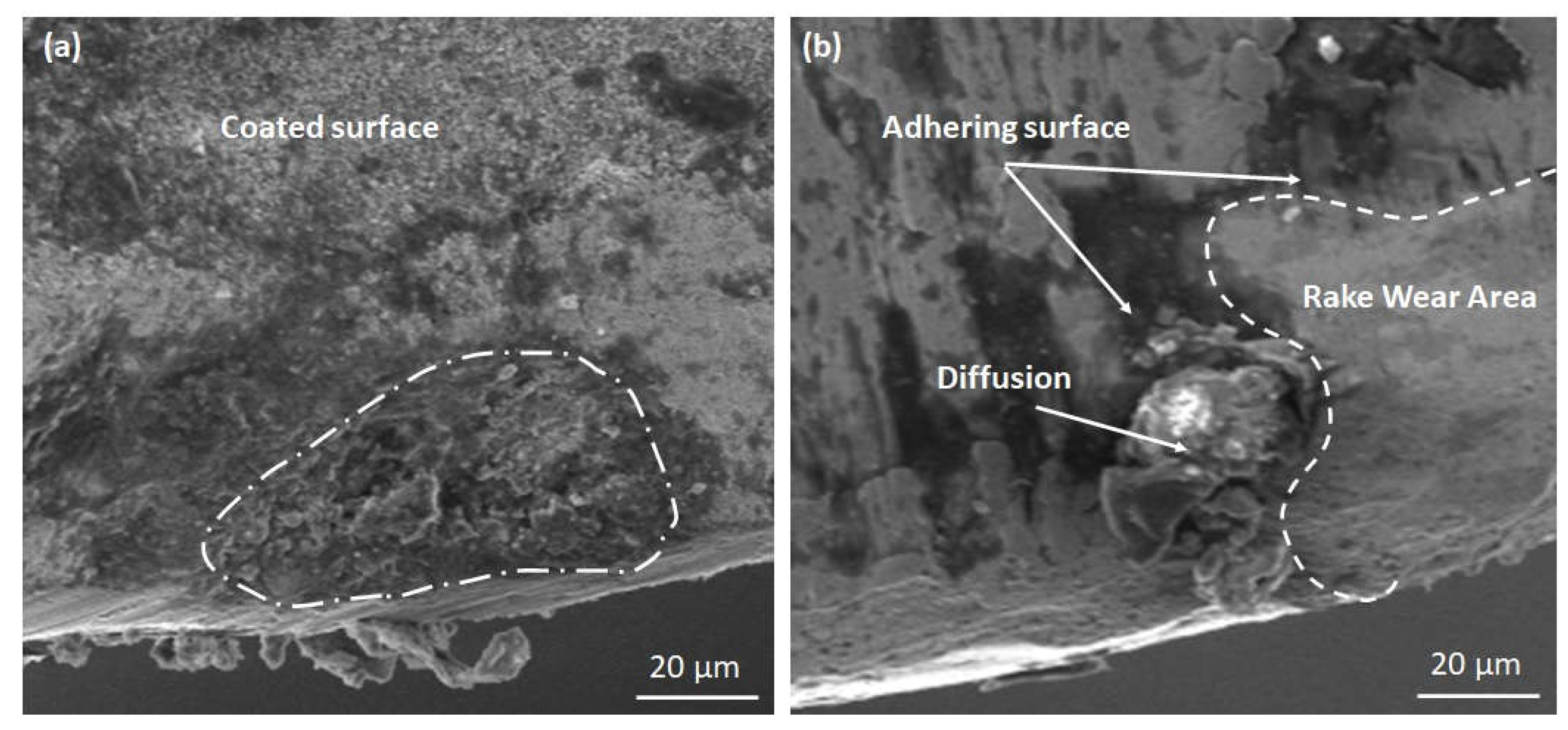
Figure 1a,b shows the EDS analysis of the workpiece (Custom-450 grade stainless steel) and insert (tungsten carbide tool with TiAlSiN coating). The findings of the EDS analysis (Figure 1a) show the peak of iron (Fe), chromium (Cr), nickel (Ni), manganese (Mn), molybdenum (Mo), and copper (Cu). However, we can see the peak of titanium (Ti), aluminum (Al), and cobalt (Co) in Figure 1b. We can observe that the major alloying element was Ti. Figure 2a,b shows the SEM images of the tungsten carbide insert coated with TiAlSiN. Figure 2a shows the insert just before the machining of the sample. It was observed the surface coated with TiAlSiN shows a fine structure over the surface. This structure is evenly distributed over the surface. Due to cryogenic treatment of 36 h, we can see the formation of some non-uniform brittle structures [29]. This may be formed due to the treatment of the sample, which would have caused some precipitate formation over the surface. Figure 2b shows the insert just after the machining of the sample. We can clearly see the wear of the rake area due to the machining of sample. The indicated areas where the tool’s cutting edge has an uneven feature that causes edge wear may be a distinctive mechanism of adhesive wear. The chemical affinity between the workpiece material and the cutting tool frequently causes adhesive wear, which leads to BUE development at the insert–chip interface [30]. There is a diffusion that may be attributed to the concentration gradient; atoms from the high-concentration zone diffuse into the low-concentration zone [31].
3.2. Surface Roughness
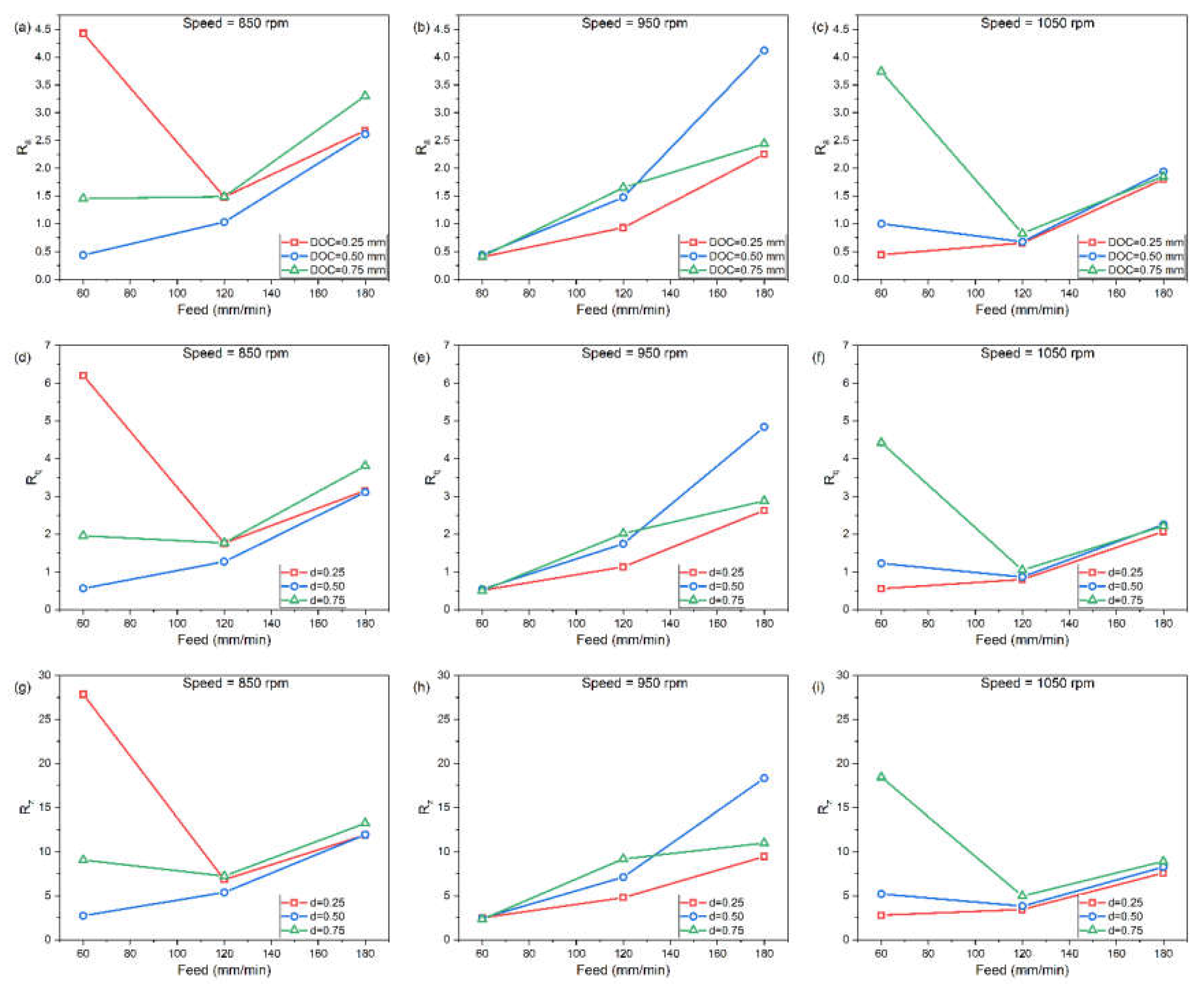
The surface roughness was measured at various levels of the cutting speed, feed, and the depth of cuts in the turning operations. The surface roughness values for each experiment with the coated insert cryogenic for 36 h are shown in Table 2. Three roughness parameters were calculated as Ra, Rq, and Rz. Where Ra is the Roughness Average (arithmetic average of the absolute values of the profile heights over the evaluation length), Rq is the RMS Roughness (root mean square average of the profile heights over the evaluation length), and Rz is the Average Maximum Height of the Profile, respectively. In the majority of the studies, the Ra is considered as the major parameter, which is influenced by the input variables such as the feed, speed, and depth of cut. In this present study, we will consider the Ra as the surface roughness measuring parameter. All the three parameters (Ra, Rq, and Rz) with respect to speed, feed and DOC are shown in Figure 3a–i. From Figure 3a, it can be observed that with a lower feed (60 mm/min) and DOC (0.25 mm), there is an increase in the surface roughness values. The sudden increase in the roughness value may be due to the as-rolled condition of the steel, which may have altered the hardness value in the sample. These conditions in the sample would have given an increase in the roughness value. It is reported that the increase in the hardness value increases the surface roughness of the sample [32]. On increasing the DOC with the same feed rate, the roughness of the sample reduces as compared to the sample measured with slow feed. With an increase in the feed rate of 120 mm/min, the sample with a DOC of 0.25 mm shows an exponentially lower value of surface roughness. However, for the other two parameters (DOC of 0.50 and 0.75 mm), there was a slight increase in the roughness values. However, when increasing the DOC (0.75 mm) even more, there is an appreciable change in the roughness value. By increasing the speed to 950 rpm, the surface roughness was almost the same for all feed of 60 mm/min and the value of roughness increased with the increasing feed (180 mm/min), as shown in Figure 3b. It was observed that there is a sudden increase in the surface roughness of the sample with a feed of 180 mm/min and a DOC of 0.50 mm. The sudden increase may be attributed to the change in the microstructural behavior in the sample. It was reported that with the increase in the hardness and surface roughness, there is a reduction in the ductility of the sample [32], when increasing the speed to 1050 rpm. Almost similar trends were observed with increasing the feed and depth of cut, as the surface roughness increases. Thus, we can conclude with the findings of this study that the increase in the feed and depth of cut increases the surface roughness. However, if we observe the speed, we can find that with the Increase in the speed from 850 rpm, 950 rpm, and 1050 rpm. there is a reduction in the surface roughness except for the samples with a speed of 950 rpm, a feed 180 mm/min, and a DOC 0.50 mm. This would have been caused by to metallurgical defects in the sample and could be avoided by proper heat treatment of the alloy. It can be summarized that the DOC has more influence on the surface roughness compared to the feed and cutting speed. With the increase in the DOC, the surface roughness increases. The value of Rq and Rz has also shown a similar trend in the graphs, as shown in Figure 3a–i. Bhushan et al. investigated the machining and surface parameters on an aluminum alloy. We observed similar findings related to cutting force, feed, and DOC [33]. The effect of cryogenic treatment in the insert has given better results than the conventional inserts (austenitic based inserts) [34]. They have reported an improvement in the surface roughness and dimensional precisions. Additionally, the tool life of the inserts has been increased for both negative and positive inserts when used in CO2 cryogenic treatment [35].
3.3. Analysis of Forces
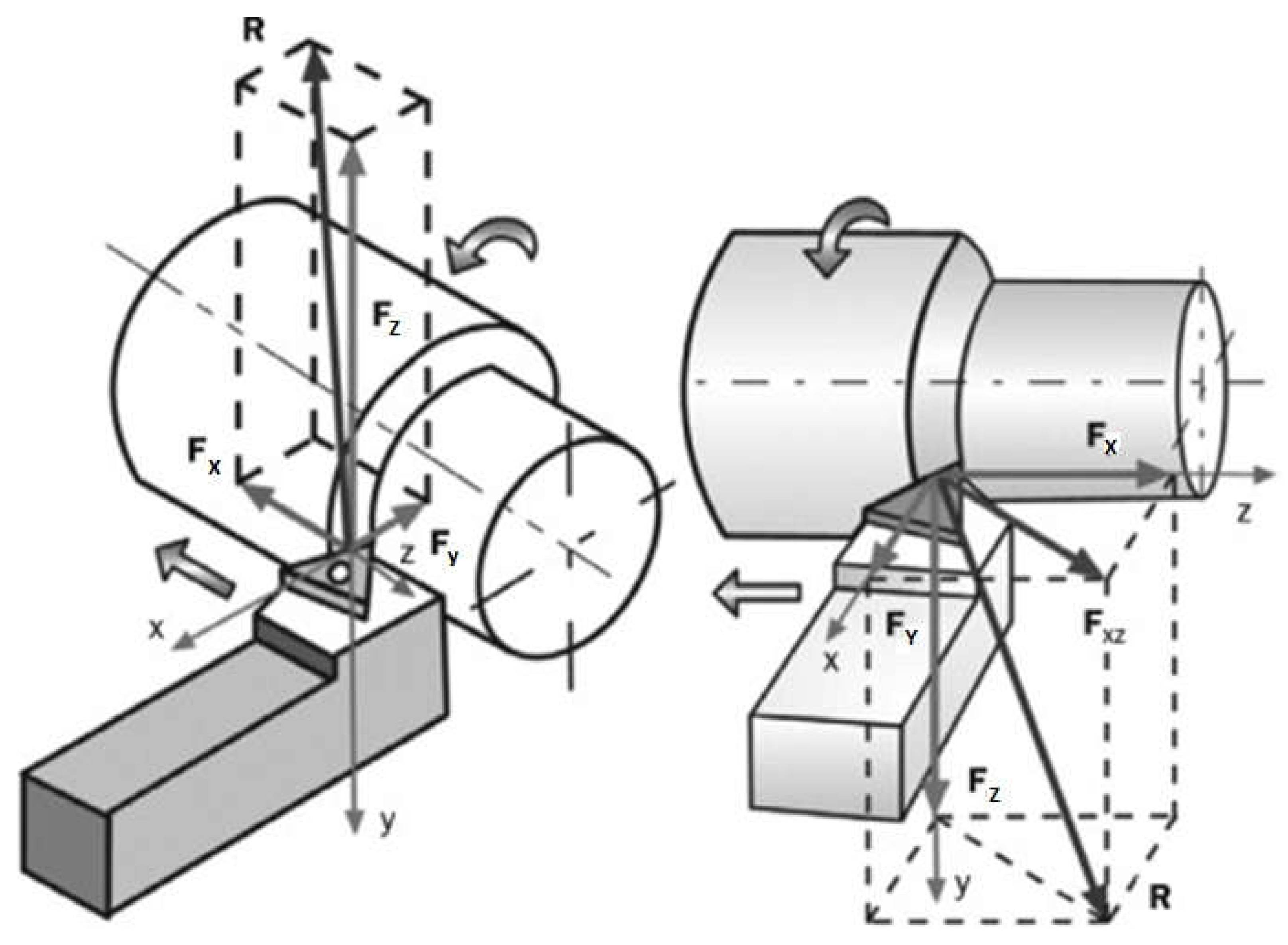
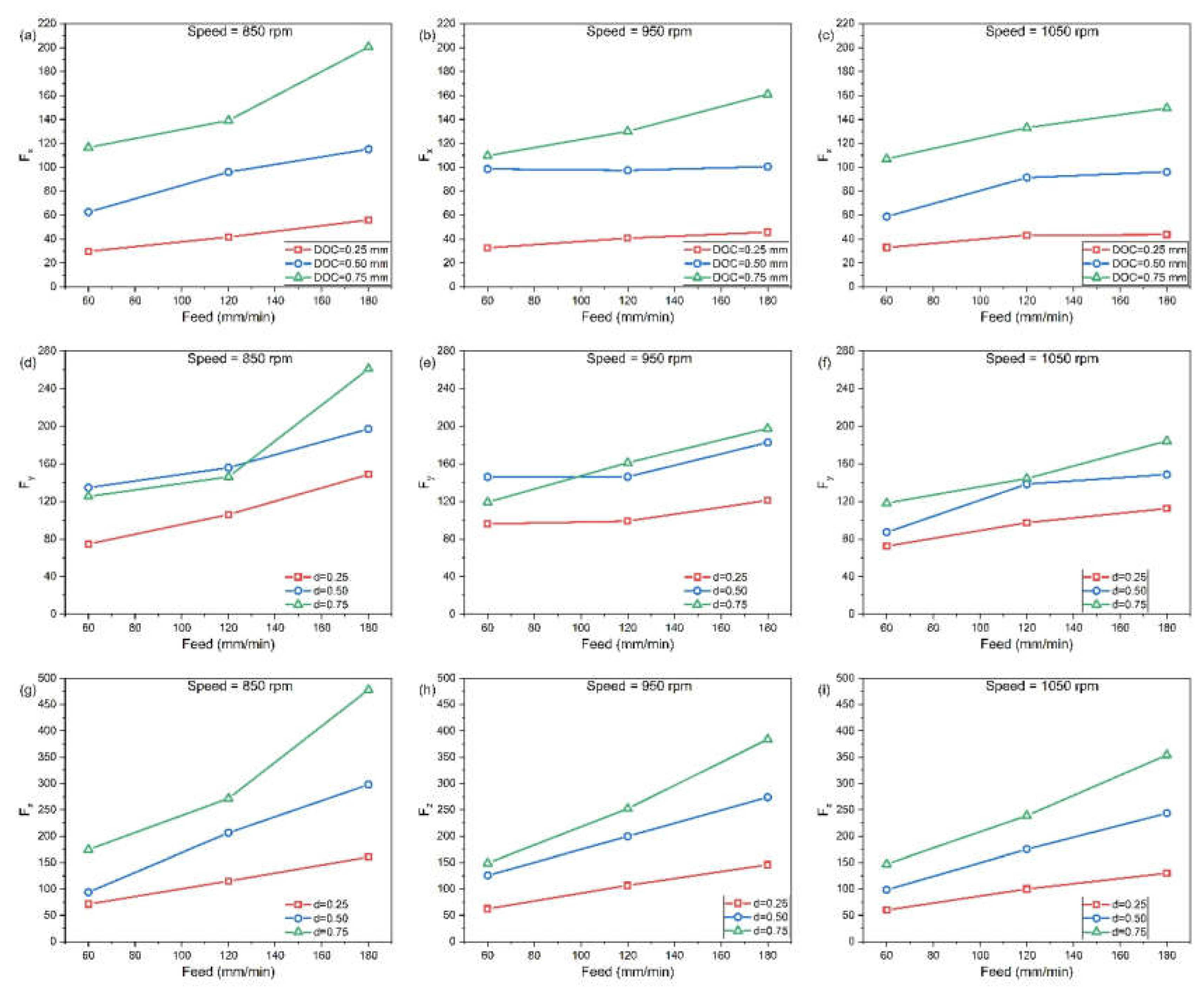
The forces were measured at various levels of the cutting speed, feed, and the depth of cuts in the turning operations. The force values for each experiment with the coated insert cryogenic for 36 h are shown in Table 2. Three forces were calculated, namely, the feed force (Fx), thrust force (Fy), and cutting force (Fz), respectively. Figure 4 shows the schematic representation of various forces acting on a tool. Figure 5a–i shows various graphs in which forces are calculated with respect to changes in speed, feed, and DOC. Figure 5a–c shows the effect of feed, DOC, and speed, with respect to the feed force (Fx). It was observed in Figure 5a that with an increase in the DOC, the feed force increases. From the figure, we can clearly see that with a lower DOC, the feed force was lower, but by increasing the feed from 60 to 120 mm/min, the feed force also increases. Similar observations were obtained by the other two rotation speeds (950 and 1050 rpm). Figure 5d–f shows the effect of feed, DOC, and speed, with respect to the thrust force (Fy). In Figure 5a it is observed that with the constant feed of 60 mm/min, there is an increase in the thrust force with a different DOC. Similar results were obtained by the feed of 120 mm/min. However, with an increase in the feed to 180 mm/min, there is a sudden increase in the graph (DOC of 0.75). This increase in the thrust force is due to the increase in the roughness value (Figure 3d). Similar findings were observed at other speeds (950 and 1050 rpm). Additionally, with the increase in the speed, the thrust force reduces. Figure 5g–i shows the effect of the feed, DOC, and speed, with respect to the cutting force (Fz). It was observed that with the increase in the DOC, the cutting force increases for all the specimens. With a lower rotational speed (850 rpm), the cutting force is higher, as compared to the sample in which the rotational speed is more (1050 rpm). Some authors proposed a correlation between the tool wear, cutting force, and surface roughness. They observed that the increase in duration increases the wear rate. First, wear increases gradually due to the protective covering layer. Then, during a subsequent period when the covering vanishes and the carbide is exposed, cratering and adhesion take place. Additionally, with respect to time, the surface roughness also increases [36]. Similar findings were observed from the carbide insert coated with TiAlSiN in our findings.
4. Conclusions
This study relates to the experimental investigation performed on machining forces (F) and the roughness (Ra) during the turning of Custom-450 grade stainless steel using coated and cryogenic-treated tool inserts. The conclusions drawn from this study are as follows:
- After undergoing cryogenic treatment for 36 h, the coated inserts exhibited a superior performance and reduced wear across all the cutting parameters.
- SEM analysis shows a better adhesion of coating over the carbide inserts. After machining the steel, the coated insert shows wear over the surface of the insert. The wear over the insert shows the removal of the coating over the surface.
- The observed reduction in ductility was attributed to alterations in the microstructure, coinciding with an increase in the surface hardness and roughness.
- The primary component influencing surface roughness is the depth of cut. A rougher surface over the specimen may be caused due to the result of a greater amount of plastic deformation in the working sample.
- As the cutting speed increased, the wear on the tungsten carbide inserts decreased. Conversely, an increase in the feed led to a significant rise in the tool wear. The risk of tool wear was found to be positively correlated with an increasing depth of cut. Nevertheless, it was observed that the most significant factor impacting the tool wear was the depth of cut.
Author Contributions
Conceptualization, M.K., E.P., R.C., and M.E.; investigation, M.K.; methodology, M.K., E.P., R.C., and M.E.; writing—original draft, M.K. and E.P.; writing—review and editing, R.C. and M.E. All authors have read and agreed to the published version of the manuscript.
Funding
This research received no external funding.
Institutional Review Board Statement
Not applicable.
Informed Consent Statement
Not applicable.
Data Availability Statement
The data presented in this study are available through email upon request to the corresponding author.
Conflicts of Interest
The authors declare no conflict of interest.
References
- Rao, C.J.; Rao, D.N.; Srihari, P. Influence of Cutting Parameters on Cutting Force and Surface Finish in Turning Operation. Procedia Eng. 2013, 64, 1405–1415. [Google Scholar] [CrossRef] [Green Version]
- Valera, H.Y.; Bhavsar, S.N. Experimental Investigation of Surface Roughness and Power Consumption in Turning Operation of EN 31 Alloy Steel. Procedia Technol. 2014, 14, 528–534. [Google Scholar] [CrossRef]
- Sata, T.; Li, M.; Takata, S.; Hiraoka, H.; Li, C.; Xing, X.; Xiao, X. Analysis of Surface Roughness Generation in Turning Operation and its Applications. CIRP Ann. 1985, 34, 473–476. [Google Scholar] [CrossRef]
- Chen, Y.; Sun, S.; Zhang, T.; Zhou, X.; Li, S. Effects of post-weld heat treatment on the microstructure and mechanical properties of laser-welded NiTi/304SS joint with Ni filler. Mater. Sci. Eng. A 2020, 771, 138545. [Google Scholar] [CrossRef]
- Yuhua, C.; Yuqing, M.; Weiwei, L.; Peng, H. Investigation of welding crack in micro laser welded NiTiNb shape memory alloy and Ti6Al4V alloy dissimilar metals joints. Opt. Laser Technol. 2017, 91, 197–202. [Google Scholar] [CrossRef]
- Umurani, K.; Siregar, R.A. Development of Dynamometer for Cutting Force Measurement in Turning Operation. IOP Conf. Ser. Mater. Sci. Eng. 2019, 705, 012051. [Google Scholar] [CrossRef]
- Wang, S.; Chen, Y.; Gu, C.; Sai, Q.; Lei, T.; Williams, J. Antifouling Coatings Fabricated by Laser Cladding. Coatings 2023, 13, 397. [Google Scholar] [CrossRef]
- He, Y.; Xiao, G.; Zhu, S.; Liu, G.; Liu, Z.; Deng, Z. Surface formation in laser-assisted grinding high-strength alloys. Int. J. Mach. Tools Manuf. 2023, 186, 104002. [Google Scholar] [CrossRef]
- Saraswat, N.; Yadav, A.; Kumar, A.; Srivastava, B.P. Optimization of Cutting Parameters in Turning Operation of Mild Steel. Int. Rev. Appl. Eng. Res. 2014, 4, 251–256. [Google Scholar]
- Liang, L.; Xu, M.; Chen, Y.; Zhang, T.; Tong, W.; Liu, H.; Li, H. Effect of welding thermal treatment on the micro-structure and mechanical properties of nickel-based superalloy fabricated by selective laser melting. Mater. Sci. Eng. A Struct. Mater. Prop. Microstruct. Process. 2021, 819, 141507. [Google Scholar] [CrossRef]
- Nalbant, M.; Gökkaya, H.; Toktaş, I.; Sur, G. The experimental investigation of the effects of uncoated, PVD-and CVD-coated cemented carbide inserts and cutting parameters on surface roughness in CNC turning and its prediction using artificial neural networks. Robot. Comput. Integr. Manuf. 2009, 25, 211–223. [Google Scholar] [CrossRef]
- Lim, G.H. Tool-wear monitoring in machine turning. J. Mater. Process. Technol. 1995, 51, 25–36. [Google Scholar] [CrossRef]
- Kivak, T. Optimization of surface roughness and flank wear using the Taguchi method in milling of Hadfield steel with PVD and CVD coated inserts. Measurement 2014, 50, 19–28. [Google Scholar] [CrossRef]
- Hodgson, T.; Trendler, P.H.H.; Micheletti, G.F. Turning hardened tool steels with cubic boron nitride inserts. CIRP Ann. 1981, 30, 63–66. [Google Scholar] [CrossRef]
- Andrewes, C.J.E.; Feng, H.Y.; Lau, W.M. Machining of an aluminum/SiC composite using diamond inserts. J. Mater. Process. Technol. 2000, 102, 25–29. [Google Scholar] [CrossRef]
- Lakshmanan, S.; Kumar, M.P.; Dhananchezian, M.; Yuvaraj, N. Investigation of monolayer coated WC inserts on turning Ti-alloy. Mater. Manuf. Process. 2020, 35, 826–835. [Google Scholar] [CrossRef]
- Kainz, C.; Schalk, N.; Tkadletz, M.; Mitterer, C.; Czettl, C. Microstructure and mechanical properties of CVD TiN/TiBN multilayer coatings. Surf. Coat. Technol. 2019, 370, 311–319. [Google Scholar] [CrossRef]
- Ezugwu, E.O.; Wang, Z.M. Titanium alloys and their machinability—A review. J. Mater. Process. Technol. 1997, 68, 262–274. [Google Scholar] [CrossRef]
- Emel, E.; Kannatey-Asibu, E. Tool Failure Monitoring in Turning by Pattern Recognition Analysis of AE Signals. J. Eng. Ind. 1988, 110, 137–145. [Google Scholar] [CrossRef]
- Shokrani, A.; Dhokia, V.; Newman, S.T. Investigation of the effects of cryogenic machining on surface integrity in CNC end milling of Ti–6Al–4V titanium alloy. J. Manuf. Process. 2016, 21, 172–179. [Google Scholar] [CrossRef] [Green Version]
- Pereira, O.; Celaya, A.; Urbikaín, G.; Rodríguez, A.; Fernández-Valdivielso, A.; López de Lacalle, L.N. CO2 cryogenic milling of Inconel 718: Cutting forces and tool wear. J. Mater. Res. Technol. 2020, 9, 8459–8468. [Google Scholar] [CrossRef]
- Gandarias, A.; de Lacalle, L.N.L.; Aizpitarte, X.; Lamikiz, A. Study of the performance of the turning and drilling of austenitic stainless steels using two coolant techniques. Int. J. Mach. Mach. Mater. 2008, 3, 1–17. [Google Scholar] [CrossRef]
- Pereira, O.; Celaya, A.; Urbikaín, G.; Rodríguez, A.; Fernández-Valdivielso, A.; de Lacalle, L.N.L. Simulation of Cryo-cooling to Improve Super Alloys Cutting Tools. Int. J. Precis. Eng. Manuf. Green Technol. 2022, 9, 73–82. [Google Scholar] [CrossRef]
- Suárez, A.; de Lacalle, L.N.L.; Polvorosa, R.; Veiga, F.; Wretland, A. Effects of high-pressure cooling on the wear patterns on turning inserts used on alloy IN718. Mater. Manuf. Process. 2016, 32, 678–686. [Google Scholar] [CrossRef]
- Amigo, F.J.; Urbikain, G.; López de Lacalle, L.N.; Pereira, O.; Fernández-Lucio, P.; Fernández-Valdivielso, A. Prediction of cutting forces including tool wear in high-feed turning of Nimonic® C-263 superalloy: A geometric distortion-based model. Measurement 2023, 211, 112580. [Google Scholar] [CrossRef]
- Zhang, X.; Yu, T.; Xu, P.; Zhao, J. In-process stochastic tool wear identification and its application to the improved cutting force modeling of micro milling. Mech. Syst. Signal Process. 2022, 164, 108233. [Google Scholar] [CrossRef]
- Behera, R.R.; Ghadai, R.K.; Kalita, K.; Banerjee, S. Simultaneous prediction of delamination and surface roughness in drilling GFRP composite using ANN. Int. J. Plast. Technol. 2016, 20, 424–450. [Google Scholar] [CrossRef]
- Ragavendran, U.; Ghadai, R.K.; Bhoi, A.K.; Ramachandran, M.; Kalita, K. Sensitivity analysis and optimization of EDM process parameters. Trans. Can. Soc. Mech. Eng. 2018, 43, 13–25. [Google Scholar] [CrossRef]
- Varghese, V.; Ramesh, M.R.; Chakradhar, D. Experimental investigation of cryogenic end milling on maraging steel using cryogenically treated tungsten carbide-cobalt inserts. Int. J. Adv. Manuf. Technol. 2019, 105, 2001–2019. [Google Scholar] [CrossRef]
- Kaynak, Y.; Gharibi, A. Progressive tool wear in cryogenic machining: The effect of liquid nitrogen and carbon dioxide. J. Manuf. Mater. Process. 2018, 2, 31. [Google Scholar] [CrossRef] [Green Version]
- Parsi, P.K.; Kotha, R.S.; Routhu, T.; Pandey, S.; Dwivedy, M. Machinability evaluation of coated carbide inserts in turning of super-duplex stainless steel. SN Appl. Sci. 2020, 2, 1–19. [Google Scholar] [CrossRef]
- Zurita-Hurtado, O.J.; di Graci-Tiralongo, V.C.; Capace-Aguirre, M.C. Effect of surface hardness and roughness produced by turning on the torsion mechanical properties of annealed AISI 1020 steel. Rev. Fac. Ing. 2017, 2017, 55–59. [Google Scholar] [CrossRef] [Green Version]
- Bhushan, R.K. Impact of nose radius and machining parameters on surface roughness, tool wear and tool life during turning of AA7075/SiC composites for green manufacturing. Mech. Adv. Mater. Mod. Process. 2020, 6, 1. [Google Scholar] [CrossRef]
- Das, P.P.; Gupta, P.; Ghadai, R.K.; Ramachandran, M.; Kalita, K. Optimization of turning process parameters by Taguchi-based Six Sigma. Mech. Mech. Eng. 2017, 21, 649–656. [Google Scholar]
- Pereira, O.; Rodríguez, A.; Fernández-Valdivielso, A.; Barreiro, J.; Fernández-Abia, A.I.; López-De-Lacalle, L.N. Cryogenic Hard Turning of ASP23 Steel Using Carbon Dioxide. Procedia Eng. 2015, 132, 486–491. [Google Scholar] [CrossRef]
- Fernández-Valdivielso, A.; López De Lacalle, L.N.; Urbikain, G.; Rodriguez, A. Detecting the key geometrical features and grades of carbide inserts for the turning of nickel-based alloys concerning surface integrity. Proc. Inst. Mech. Eng. C J. Mech. Eng. Sci. 2016, 230, 3725–3742. [Google Scholar] [CrossRef]
- Astakhov, V.P. Turning. In Modern Machining Technology; Elsevier: Amsterdam, The Netherlands, 2011; pp. 1–78. [Google Scholar]
Figure 1.
EDS analysis of (a) base materials (Custom-450 grade stainless steel) and (b) tungsten carbide tool with TiAlSiN coating.
Figure 1.
EDS analysis of (a) base materials (Custom-450 grade stainless steel) and (b) tungsten carbide tool with TiAlSiN coating.

Figure 2.
SEM images of tungsten carbide insert coated with TiAlSiN cryogenic treated for 36 h (a) before machining and (b) after machining.
Figure 2.
SEM images of tungsten carbide insert coated with TiAlSiN cryogenic treated for 36 h (a) before machining and (b) after machining.

Figure 3.
Influence of feed and depth of cut on surface roughness at various speeds. Effect on Average Roughness at speed (a) 850 rpm, (b) 950 rpm (c) 1050 rpm; Effect on RMS Roughness at speed (d) 850 rpm, (e) 950 rpm (f)1050 rpm; Effect on Average Maximum Height of the Profile at speed (g) 850 rpm, (h) 950 rpm (i)1050 rpm.

Figure 4.
Schematic representation of various forces acting on a tool [37].
Figure 4.
Schematic representation of various forces acting on a tool [37].

Figure 5.
Influence of feed and depth of cut on forces at various speeds. Effect on feed force (Fx) at speed (a) 850 rpm, (b) 950 rpm (c) 1050 rpm; Effect on thrust force (Fy) at speed (d) 850 rpm, (e) 950 rpm (f) 1050 rpm; Effect on cutting force (Fz) at speed (g) 850 rpm, (h) 950 rpm (i) 1050 rpm.


Table 1.
Control factors and levels.
| Control Factors | Unit | Levels | ||
|---|---|---|---|---|
| 1 | 2 | 3 | ||
| Speed | rpm | 850 | 950 | 1050 |
| Feed | mm/min | 60 | 120 | 180 |
| DOC | mm | 0.25 | 0.5 | 0.75 |
Table 2.
Surface roughness and cutting force values when coated and cryogenic 36 h treated insert.
| Speed | Feed | Depth of Cut | Ra | Rq | Rz | Fx | Fy | Fz |
|---|---|---|---|---|---|---|---|---|
| 1050 | 180 | 0.75 | 1.853 | 2.218 | 8.906 | 149.3 | 184.3 | 353.9 |
| 1050 | 120 | 0.75 | 0.827 | 1.045 | 4.961 | 133 | 144.3 | 238.8 |
| 1050 | 60 | 0.75 | 3.741 | 4.423 | 18.428 | 107 | 118.2 | 147 |
| 950 | 180 | 0.75 | 2.439 | 2.88 | 10.977 | 161 | 197.6 | 383.8 |
| 950 | 120 | 0.75 | 1.652 | 2.016 | 9.185 | 130 | 161.1 | 252.1 |
| 950 | 60 | 0.75 | 0.414 | 0.498 | 2.315 | 109.6 | 119.1 | 148.7 |
| 850 | 180 | 0.75 | 3.303 | 3.81 | 13.239 | 200.5 | 260.9 | 478.1 |
| 850 | 120 | 0.75 | 1.489 | 1.766 | 7.24 | 139.1 | 146.1 | 271.5 |
| 850 | 60 | 0.75 | 1.454 | 1.955 | 9.055 | 116.5 | 125.2 | 174.3 |
| 1050 | 180 | 0.5 | 1.941 | 2.258 | 8.268 | 96.21 | 148.7 | 243.2 |
| 1050 | 120 | 0.5 | 0.678 | 0.864 | 3.822 | 91.27 | 138.4 | 175.1 |
| 1050 | 60 | 0.5 | 1.003 | 1.223 | 5.204 | 58.77 | 87.06 | 98.33 |
| 950 | 180 | 0.5 | 4.12 | 4.842 | 18.321 | 100.5 | 182.7 | 273.7 |
| 950 | 120 | 0.5 | 1.475 | 1.743 | 7.112 | 97.4 | 146.1 | 199.6 |
| 950 | 60 | 0.5 | 0.442 | 0.54 | 2.449 | 98.57 | 146 | 125.6 |
| 850 | 180 | 0.5 | 2.612 | 3.111 | 11.933 | 115.1 | 197 | 297.7 |
| 850 | 120 | 0.5 | 1.032 | 1.27 | 5.372 | 95.97 | 155.9 | 206.2 |
| 850 | 60 | 0.5 | 0.44 | 0.557 | 2.725 | 62.59 | 134.6 | 93.88 |
| 1050 | 180 | 0.25 | 1.803 | 2.069 | 7.585 | 43.59 | 112.4 | 129.9 |
| 1050 | 120 | 0.25 | 0.654 | 0.797 | 3.424 | 43.26 | 97.35 | 99.89 |
| 1050 | 60 | 0.25 | 0.446 | 0.554 | 2.778 | 32.93 | 72.29 | 60.01 |
| 950 | 180 | 0.25 | 2.253 | 2.629 | 9.454 | 45.68 | 121 | 146 |
| 950 | 120 | 0.25 | 0.933 | 1.134 | 4.782 | 40.7 | 98.98 | 106.7 |
| 950 | 60 | 0.25 | 0.405 | 0.51 | 2.479 | 32.57 | 95.96 | 62.48 |
| 850 | 180 | 0.25 | 2.68 | 3.157 | 11.9 | 55.93 | 148.6 | 160.5 |
| 850 | 120 | 0.25 | 1.485 | 1.759 | 6.831 | 41.67 | 106 | 114.9 |
| 850 | 60 | 0.25 | 4.427 | 6.209 | 27.853 | 29.73 | 74.59 | 71.19 |
Disclaimer/Publisher’s Note: The statements, opinions and data contained in all publications are solely those of the individual author(s) and contributor(s) and not of MDPI and/or the editor(s). MDPI and/or the editor(s) disclaim responsibility for any injury to people or property resulting from any ideas, methods, instructions or products referred to in the content. |
© 2023 by the authors. Licensee MDPI, Basel, Switzerland. This article is an open access article distributed under the terms and conditions of the Creative Commons Attribution (CC BY) license (https://creativecommons.org/licenses/by/4.0/).
Share and Cite
MDPI and ACS Style
Karthick, M.; Pavithra, E.; Cep, R.; Elangovan, M. Machining of Custom-450 Grade Stainless Steel Using TiAlSiN-Coated Tungsten Carbide Tool Inserts. Processes 2023, 11, 1037. https://doi.org/10.3390/pr11041037
AMA Style
Karthick M, Pavithra E, Cep R, Elangovan M. Machining of Custom-450 Grade Stainless Steel Using TiAlSiN-Coated Tungsten Carbide Tool Inserts. Processes. 2023; 11(4):1037. https://doi.org/10.3390/pr11041037
Chicago/Turabian StyleKarthick, Muniyappan, Ekambaram Pavithra, Robert Cep, and Muniyandy Elangovan. 2023. "Machining of Custom-450 Grade Stainless Steel Using TiAlSiN-Coated Tungsten Carbide Tool Inserts" Processes 11, no. 4: 1037. https://doi.org/10.3390/pr11041037
Note that from the first issue of 2016, this journal uses article numbers instead of page numbers. See further details here.