Article

CNC Turning of an Additively Manufactured Complex Profile Ti6Al4V Component Considering the Effect of Layer Orientations

1
Industrial Engineering Department, College of Engineering, Taibah University, Medinah 41411, Saudi Arabia
2
Industrial Engineering Department, College of Engineering, King Saud University, Riyadh 11421, Saudi Arabia
3
Industrial Engineering Department, College of Engineering and Architecture, Alyamamah University, Riyadh 11512, Saudi Arabia
*
Author to whom correspondence should be addressed.
Processes 2023, 11(4), 1031; https://doi.org/10.3390/pr11041031
Submission received: 6 March 2023 / Revised: 21 March 2023 / Accepted: 23 March 2023 / Published: 29 March 2023
(This article belongs to the Special Issue Computer-Aided Manufacturing Technologies in Mechanical Field)

Abstract

:
Electron beam melting (EBM) is one example of a 3D printing technology that has shown great promise and advantages in the fabrication of medical devices such as dental and orthopedic implants. However, these products require high surface quality control to meet the specifications; thus, post-processing, such as with machining processes, is required to improve surface quality. This paper investigates the influence of two-part orientations of Ti6Al4V EBM parts on the CNC machining (turning) process. The two possible EBM part orientations used in this work are across EBM layers (AL) and parallel to the EBM layer (PL). The effect of the EBM Ti6Al4V part orientations is examined on surface roughness, power consumption, chip morphology, tool flank wear, and surface morphology during the dry turning, while using uncoated carbide tools at different feed rates and cutting speeds. The results showed that the AL orientation had better surface quality control and integrity after machining than PL orientation. Using the same turning parameters, the difference between the roughness (Ra) value for AL (0.36 μm) and PL (0.79 μm) orientations is about 54%. Similarly, the power consumption in AL orientation differs by 19% from the power consumption in PL orientation. The chip thickness ratio has a difference of 23% between AL and PL orientations, and the flank wear shows a 40% difference between AL and PL orientations. It is found that, when EBM components are manufactured along across-layer (AL) orientations, the impact of part orientation during turning is minimized and machined surface integrity is improved.

1. Introduction

Ti6Al4V alloy is a promising biomaterial and has attracted a lot of attention for its potential use in the medical field due to its use in dental implants, knee and hip prostheses, bones and artificial joints, and orthopedic implants such as screws, femoral nails, etc. [1,2,3]. The mechanical properties of the Ti6Al4V alloy include high specific strength, better creep resistance and fatigue at extreme temperatures, exceptional corrosion resistance, low density, and decreased Young’s Modulus when related to Cr-Co and stainless steel alloys, making it a material with a wide range of aerospace, biomedical and other uses [4,5,6,7]. However, Ti6Al4V is hard to cut because of its limited thermal conductivity and work hardening at high temperatures. The poor machinability of Ti6Al4V reduces the quality of the processed surface and life of the cutting tool, increases power consumption and cutting forces, shortens the component life, etc. [8]. Ti6Al4V can affordably support customized implants or prostheses. Due to the fact that these implants interact with the body of a human, their surface properties must be given special consideration.
Electron beam melting (EBM) technology was introduced by Arcam AB as one of the additive manufacturing processes, and this technology can be used for fabricating parts with difficult-to-work materials such as Ti6Al4V. EBM technology is spreading rapidly due to the ability to customize parts in terms of both in-service performance and geometric characteristics. In addition, EBM is regarded as an effective method for producing complex near-net-shapes with few internal flaws [9]. However, because EBM metal components have dissimilar microstructural and mechanical properties compared to wrought metal alloys, they often require finishing processes to achieve the desired surface quality. Therefore, machining processes may still be necessary to meet the desired surface finish and geometric specifications for EBM parts [10,11] because the surface roughness is one of the essential characteristics of all biomaterials and aerospace components; thus, extensive work is required for the machinability of Ti6Al4V EBM parts.
Several studies have tried to improve the EBM process’s parameters for the lowest possible surface roughness. For example, Safdar et al. [12] determined the effect of scan speed, sample thickness, current of the beam, and focus of offset of the EBM machine on the surface topography/roughness of the Ti6Al4V EBM components. The results of Ra range from 1 to 20 µm for different samples based on the thickness and process parameter setting. Ra decreases as sample thickness and beam current increase, while offset focus and scan speed increase. Using EBM, Razavi et al. [13] studied the effects of sample thickness and geometry on mechanical properties, microstructure, and surface roughness of Ti6Al4V parts. They found that the higher surface roughness of EBM parts was caused by their thinner build thickness. The minimal surface roughness for the top and side faces was 21.13 µm and 30.82 µm, respectively. The microstructural investigations demonstrated that samples with a thinner thickness of build have less elongation at failure, finer grain size, and greater microhardness. The elongation at failure rose dramatically as the build thickness increased.
Abdeen and Palmer [14] investigated the influence of the beam current, focus of offset, and speed of beam of the EBM system on the density, surface roughness, and critical pitting temperature (CPT) of Ti6Al4V EBM components. The results demonstrated that, in comparison to the speed of the beam and the current of the beam, the focus offset had the highest effect on surface roughness. The highest obtained average surface roughness was 96.6 µm, while the lowest was 15.4 µm. The focus of offset had a larger influence on density than any other parameter. Additionally, the speed of the beam and the current of the beam had a slight influence on CPT values. Galati et al. [15] investigated how the orientation and EBM surfaces’ slope affected the surface roughness. Furthermore, they investigated the changes between the downward and upward surfaces. The results showed that the roughness of the downward surfaces was significantly higher than that of the upward surfaces. On the top surfaces, the mean roughness value (Ra) was measured to be approximately 6 µm. The average Ra values for upward and downward surfaces were approximately 15 µm and 19 µm, respectively. Using contours in the EBM process can enhance surface roughness, according to Galati and Iuliano [16]. Wang et al. [17] investigated the impacts of generating contour or continuous line strategies for enhancing surface roughness. Despite the fact that merely adjusting the processing parameters did not have a significant effect on roughness values, they concluded that surface roughness can be improved within a limited process window. Ashfaq and Al-Ahmari [18] studied the impact of beam focus offset, beam speed, beam current, line offset, and surface temperature on the surface roughness and density of EBM γ-TiAl components. The results demonstrated that the internal porosity and surface roughness are correlated to the process settings. Furthermore, the important ones among the parameters are beam speed, line offset, and beam focus offset, which played a critical role in internal surface evolution and flaw generation. According to Galati et al. [15], when using 70 µm layer thickness the vertical surface roughness (Ra) is approximately 30 µm. By thinning the layer to 50 µm, the surface roughness (Ra) can be adjusted to be between 6 and 19 µm [19]. Consequently, the optimization of EBM process parameters to provide the minimum surface roughness is limited. Therefore, additional post-processing, and a machining/finishing operation, are necessary to achieve the intended surface quality.
However, even after carrying out the in situ optimization of the EBM parameters, the final surface roughness achieved on the components was far higher than those required in aerospace (Ra 0.2–0.25 µm) [20] and medical (Ra 0.2 or below) [21] sectors. The surface roughness of EBM components has a direct correlation with the material’s friction and wear properties, and therefore with the lifespan of the component. Numerous research works have been conducted on the improvement of surface roughness of the EBM components, but they are insufficient to address all difficulties. Bertolini et al. [22] studied the effect of the turning parameters during the finishing of EBM and wrought Ti6Al4V parts on their microstructural features, surface topography, and residual stresses under flood, cryogenic cooling, and dry conditions. Based on their findings, the EBM Ti6Al4V alloy had various machinability features compared to the wrought material, and EBM parts consistently had the poorest surface finish, as also reported by Bordin et al. [23]. Coz et al. [24] investigated the machinability of Selective Laser Melting (SLM)-based Ti6Al4V components in the turning process. SLM Ti6Al4V components generated more cutting and feed forces than wrought Ti6Al4V during machining. The cutting forces compared with wrought Ti-6Al-4V were within a range of 3 to 24 percent and 10 to 21 percent as the cutting speed and feed rate increased, respectively. Chips produced with a lower feed rate were helical, whereas chips produced with a higher feed rate were long. During the two-dimensional cutting of EBM or wrought Ti6Al4V, it was discovered that cutting speed had a higher effect on chip formation than feed rate. In both SLM and wrought Ti6Al4V parts, micro-cutting did not significantly alter subsurface microstructures. Li et al. [25] investigated the turning of SLM and wrought Ti6Al4V tubes and studied the tool wear, machined surface roughness, and cutting forces at various feed rates, cutting depths, and cutting speeds. The rake face of the tools had a larger contact area with the wrought workpiece. The surface roughness of the machined surfaces of both SLM and wrought components was similar. Machining SLM components requires a higher cutting force than machining wrought components, by up to 70%. Sartori et al. [26] investigated and compared the machinability of the EBM Ti6Al4V under cryogenic cooling and dry conditions on machined surface integrity, chip morphology, and tool wear. They found that the use of cryogenic cooling compared to dry turning causes an important rise in surface roughness. Furthermore, cryogenic cooling determines a reduction in the abrasive wear of the tool. Anwar et al. [27] investigated and compared the machinability of the EBM γ-TiAl part for coated and uncoated carbide inserts on cutting forces and tool wear, morphology and surface finish, and microstructural and hardness alterations. The results demonstrated that the poor performance of the coated inserts led to higher tool wear, cutting forces and oxidation, and poor surface integrity.
Some research has demonstrated that the effect of the 3D printed layer orientations is quite significant during the finishing of the additively manufactured parts. For instance, during the milling of EBM Ti6Al4V and γ-TiAl components, the effect of the layers’ orientations has been published by [28,29]. Researchers found that even with similar machining parameters, various EBM part orientations during machining can lead to varying surface roughness. By applying heat treatment to EBM Ti6Al4V components, the part orientation effect was suppressed [30]. Another study [31] investigated the influence of laser-powder bed fused (L-PBF) fabrication Stainless Steel 316 L part orientations during milling by tuning the layer thickness through the L-PBF process. Furthermore, Lizzul et al. [32] studied L-PBF fabricated Ti6Al4V components using altered scanning strategies (chessboard and stripes) and improved surface integrity during turning operations while considering the layers’ orientations (cylindrical (across the layers) and transverse operations (along layers)). The results showed that the unique microstructure induced by the L-PBF process affects the machinability of the material depending on the strategy of scanning and/or layers orientation. The best machining performance was observed when the sample surface was cut perpendicular to the build-up direction. However, no report has yet been found in the literature to study the effect of the layers’ orientation on the finishing of the EBM complex profile components resembling implant devices.
A literature review indicates that EBM components for medical and aerospace applications must be machined in order to achieve the desired surface quality. Despite the fact that a number of researchers have adjusted EBM parameters for the fabrication of Ti6Al4V components, it has been reported that the surface roughness ranges from Ra = 6 to 96.6 µm. Furthermore, Ti6Al4V components are challenging to machine due to their directional properties, arising from the microstructure and orientations of the melted layers. The current research aims to enhance the surface quality of the EBM manufactured Ti6Al4V components by applying the turning process, with a focus on the two possible EBM part orientations (across EBM layers (AL) and parallel to EBM layers (PL)). No previous studies could be found in the literature to study the effect of the layers’ orientation on the finishing of EBM complex profile components. The turning performance is evaluated in terms of surface roughness, power consumption, chip formation, flank wear, and surface morphology at various cutting speeds and feed rates.

2. Experimental Work

Non-prismatic samples were designed and produced in different build orientations by the EBM machine (ARCAM), as shown in Figure 1. The typical particle size of the Ti6Al4V powder was 71 µm. Powdered Ti6Al4V has the chemical composition shown in Table 1. The EBM parameters are shown in Table 2, all of which were chosen since they were the ones that ARCAM had recommended as the default for producing appropriate microstructures and mechanical properties for Ti6Al4V parts [33,34]. EBM Ti6Al4V components demonstrated a hardness of 329 Hv, yield strength of 930 MPa, and tensile strength of 970 MPa.
The surface finish of components made by EBM varies from one side to the other. For instance, the EBM Ti6Al4V components in across-layers orientation have a roughness of Ra = 33 μm, as shown in Figure 1b, whereas in the parallel layers orientation they have a roughness of Ra = 20 μm, as shown in Figure 1c. Even though EBM parts were produced using the optimum parameters recommended by ARCAM [34], the surface roughness for both orientations is high, and inadequate for many applications. As a result, the EBM components require a secondary process for finishing. Here, the conventional turning process was used to accomplish the same goal of improving the surface finish. Figure 2 displays the two alternative part/EBM layers’ orientations that can be experienced throughout the turning process to improve the surface quality of the EBM parts. The first orientation is termed “tool movement perpendicular to layer planes” across layer (AL) (see Figure 2a). The second orientation is called “tool movement parallel to layers planes” parallel layer (PL) (see Figure 2b). The turning setup is shown in Figure 3a. Figure 3b displays the machined part with an enlarged view, and Figure 3c shows the enlarged view of the insert tool.
Before the actual experiments, the samples were turned with a depth of cut of 0.2 mm, a cutting speed of 30 m/min, and a feed rate of 0.1 mm per rev. The purpose of this was to level out the rough and uneven surfaces produced by EBM so that the subsequent machining could take place on a flat surface. To evaluate the impacts of EBM part orientation on turning quality, turning was carried out according to the parameters shown in Table 3. A similar range of turning parameters has been employed in previous research involving the turning of Ti6Al4V components [36,37,38,39,40].
The turning experiments were performed using a two-axis CNC lathe (EMCOMAT-E300, Germany). The spindle of this lathe can reach a maximum speed of 2200 rpm, the feed rate is 5 m/min, and the power output is 25 kW. A special turning fixture was developed to hold the part and mounted on a headstock with a three-jaw chuck, as shown in Figure 3a. Under dry conditions, tungsten carbide inserts with a corner radius of 0.4 mm and an entering angle of 95° were used from Walter, Germany (CNMG-120404 NFT). The inserts were mounted on a DCLNR tool holder. Figure 3c shows the insert and the tool holder used in the experiments. Five responses were measured, including surface roughness, power consumption, chip formation, flank wear, and surface morphology. The surface roughness was evaluated in terms of arithmetic mean roughness (Ra) using a 3D profilometer from Bruker USA (DektakXT stylus profiler) [41]. The measurement was performed in accordance with ISO 4287 using a stylus profiler with a scan speed of 75 µm/s and a resolution of 0.25 µm/pt in accordance with Gaussian regression. Ra was measured at different locations for the two-part orientations (AL and PL) after turning, and the average of five measurements was used. The electric current was measured using a single-phase cable connected to the CNC turning machine’s three-phase power supply by employing a clamp meter. The following equation was used to convert the voltage and current to power consumption [42,43,44].
Power   =   Voltage ×   Current × 3 × cos Ø
where cos Ø represents power factor value = 0.7
The chip analysis can indicate that better conditions of the machining process can be selected to enhance the surface roughness and tool wear [45,46]. After each experiment, the chips were collected. The steps for preparing the chip specimens are shown in Figure 4. Continuous chips are created during the turning of the Ti6Al4V EBM component, as shown in Figure 4a. An enlarged view of a chip is shown in Figure 4b. Ten chips were cut and mounted in a Bakelite matrix to enable the chip grinding process, see Figure 4c–f. However, at the beginning, before the mounting process, we made sure that the chips were in the correct orientation, as shown in Figure 4d, and later, to avoid any chip orientation error, the readings were taken on ten different chips. Furthermore, in Figure 4c the chips were from a single machining parameter, and three measurements were performed on each chip, i.e., totaling to 30 readings for measuring the chip thickness for a single set of machining parameters. Later, the average of 30 readings was taken, which minimizes the effect of the minor variable chip orientations. Silicon carbide papers of grit sizes 220, 400, 600, 800, 1000, 1500, and 2500 were used to grind the mounted chip samples. Figure 4g shows the maximum chip thickness measured by SEM. The chip morphology, flank wear, and surface morphologies of the turned part were measured by using a scanning electron microscope (SEM) (Model JCM 6000Plus) from Jeol, Japan.

3. Results and Discussions

3.1. Surface Roughness Evaluation

An EBM-produced part was turned in both AL and PL orientations. Figure 5 compares the Ra parameter with two alternative sets of turning parameters for each orientation. After turning, the Ra of EBM parts ranged from 0.34 to 0.78 µm. Ra was significantly smaller when the tool was moved perpendicular to the layer planes (AL) than when it was moved parallel to the layer planes (PL), as compared to [28,29]. As shown in Figure 5, there is a nearly 40% difference between the roughness values at V = 30 m/min for PL (Ra = 0.582 µm) and AL (Ra = 0.3476 µm) orientations. The difference between the roughness values for the two orientations further increased to nearly 54% when the cutting speed increased to 60 m/min. The lowest surface roughness was attained when the EBM-produced component was machined with the tool moving across to the layer planes (AL, as displayed in Figure 2). Figure 6 shows 2D roughness profiles extracted along AL and PL orientations. As a result, the 2D roughness curve for the AL orientation is smoother than that of the PL orientation. During machining in the AL orientation, the feed force was exerted on a single layer under the tool depth of cut. This led to compressive loading on the lower layers’ interfaces and prevented the layers’ ripping effect. According to Gupta et al. [47], this may be due to the improved interlayer metallurgical bonding, decreased porosity, and higher tensile strength along the AL orientation. In contrast, when the tool was moving in the PL direction, i.e., along the layers’ planes, shear forces were experienced by the layers’ interfaces, causing their possible ripping, as shown in Figure 7. This is why a higher roughness was encountered when PL orientation was considered during turning.
Figure 8 illustrates the microstructure of the EBM-fabricated Ti6Al4V component. The majority of the microstructure consists of the refined lamellar α and β phases. As a result of the varying thermal gradients along the cross-sections AA’ (AL orientation) and BB’ (PL orientation), the microstructures differ between the AA’ and BB’. The BB’ shows more distributed α and β phases, whereas the AA’ shows columnar grains. The columnar grains have more strength as compared to well-distributed α and β phases on the BB’. Therefore, when the tool moves along the EBM build direction of the AA’ (AL orientation), more resistance is encountered due to the columnar grains, resulting in the tool experiencing more wear and a higher power consumption during the machining. In contrast, in the BB’ (PL orientation) a similar phenomenon does not occur.

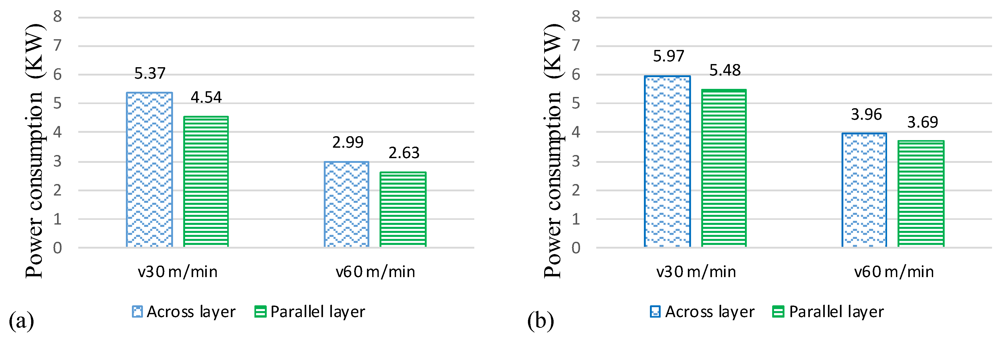
3.2. Power Consumption

During machining, the power consumption contributes to the process’s stability and facilitates the identification of optimal parameters to minimize power consumption. Figure 9 displays a graphical comparison between the two sets of turning parameters in terms of the power consumption parameter for each of the two-component orientations. The power consumption during the turning of the EBM parts varies between 2.63 and 5.97 KW, consistent with [8,48], where a similar range of turning parameters was employed. Airao and Chandrakant [48] used the Ti6Al4V parts with turning parameters of 70 m/min speed and a feed rate of 0.2 mm/rev to obtain 4 KW. Values for power consumption are high for turning across layer orientation compared to parallel layer orientation. For instance, Figure 9a shows that at a 30 m/min cutting speed, the AL orientation consumes 5.37 KW power, which is 15% higher than the AL orientation for the same turning parameters. In the AL direction, the tool interacted with a collection of the bonded EBM layers without creating shear stresses at the interfaces of the layers. This resulted in high cutting resistance from the workpiece, causing a higher power consumption for AL orientation relative to PL orientation.
This is because, in the AL orientation, the feed force (Ff) causes compressive stresses on the layers’ interfaces while the cutting force (Fc) creates the cutting action of several layers interacting with the end cutting edge, as shown in the schematic Figure 7a. The cutting action of the Fc force and compressive action of the feed force led to a good surface finish in the case of the AL orientation. At the same time, it led to more resistance from the material during cutting, attributable to the higher power consumption. In contrast, in the PL orientation, the feed force caused buckling stresses on the layer interfaces, while the cutting/tangential force caused shear stresses on the layer interfaces, as shown in the schematic Figure 7b. The buckling and shear stresses at the layer interfaces in the PL orientation weakened the material for cutting and resulted in reduced overall power consumption. Furthermore, the buckling stresses also reduced the chip thickness (see Figure 10 and Figure 11), lowering the power consumption, as the power consumption during machining is directly affected by the chip thickness [8].

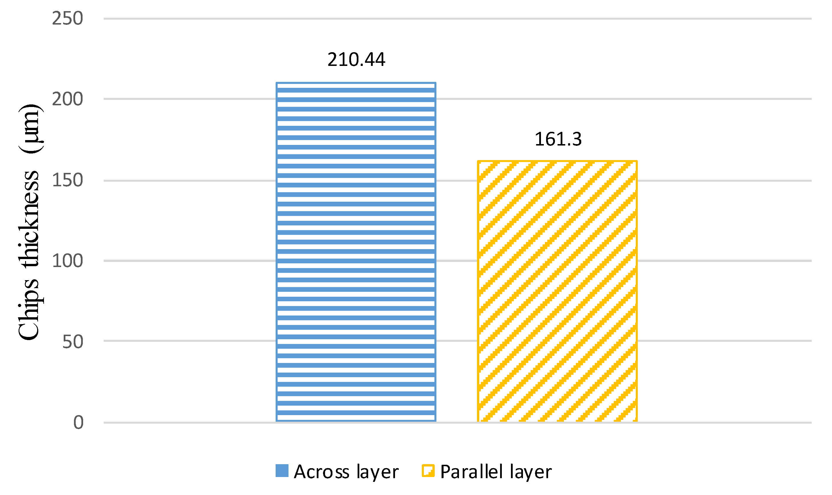
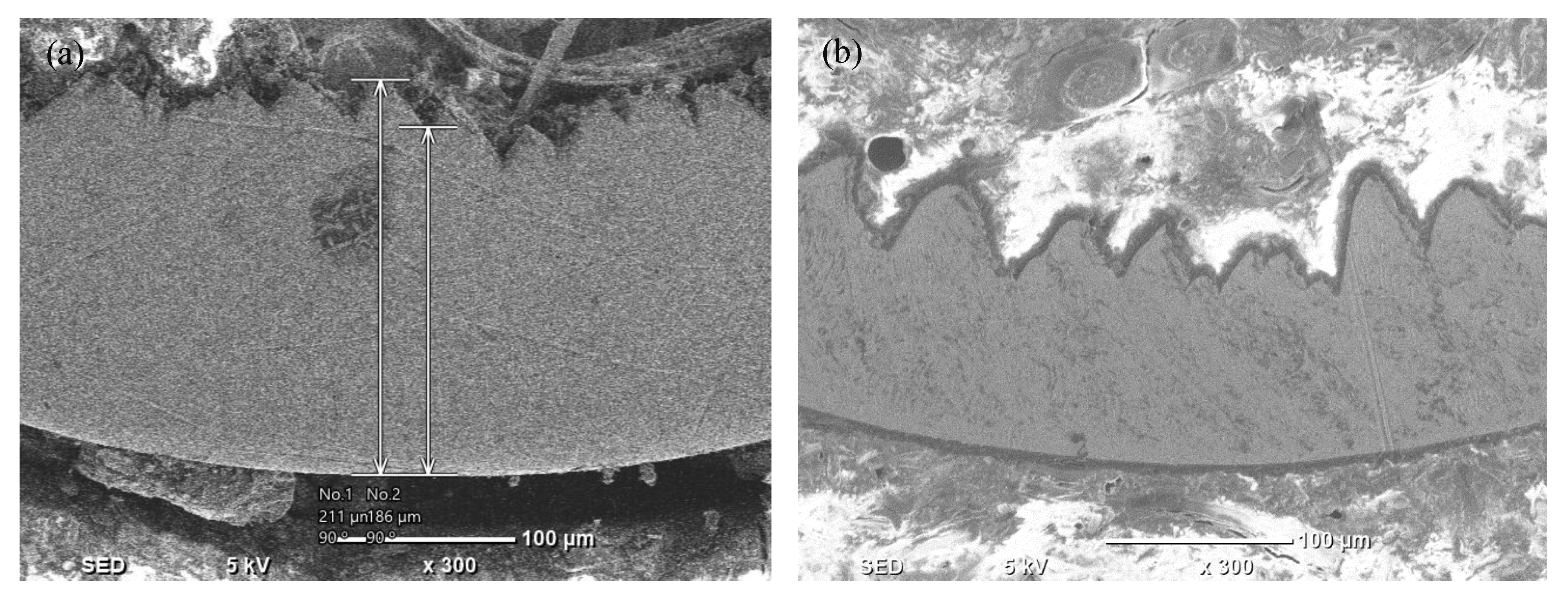
3.3. Chip Morphology
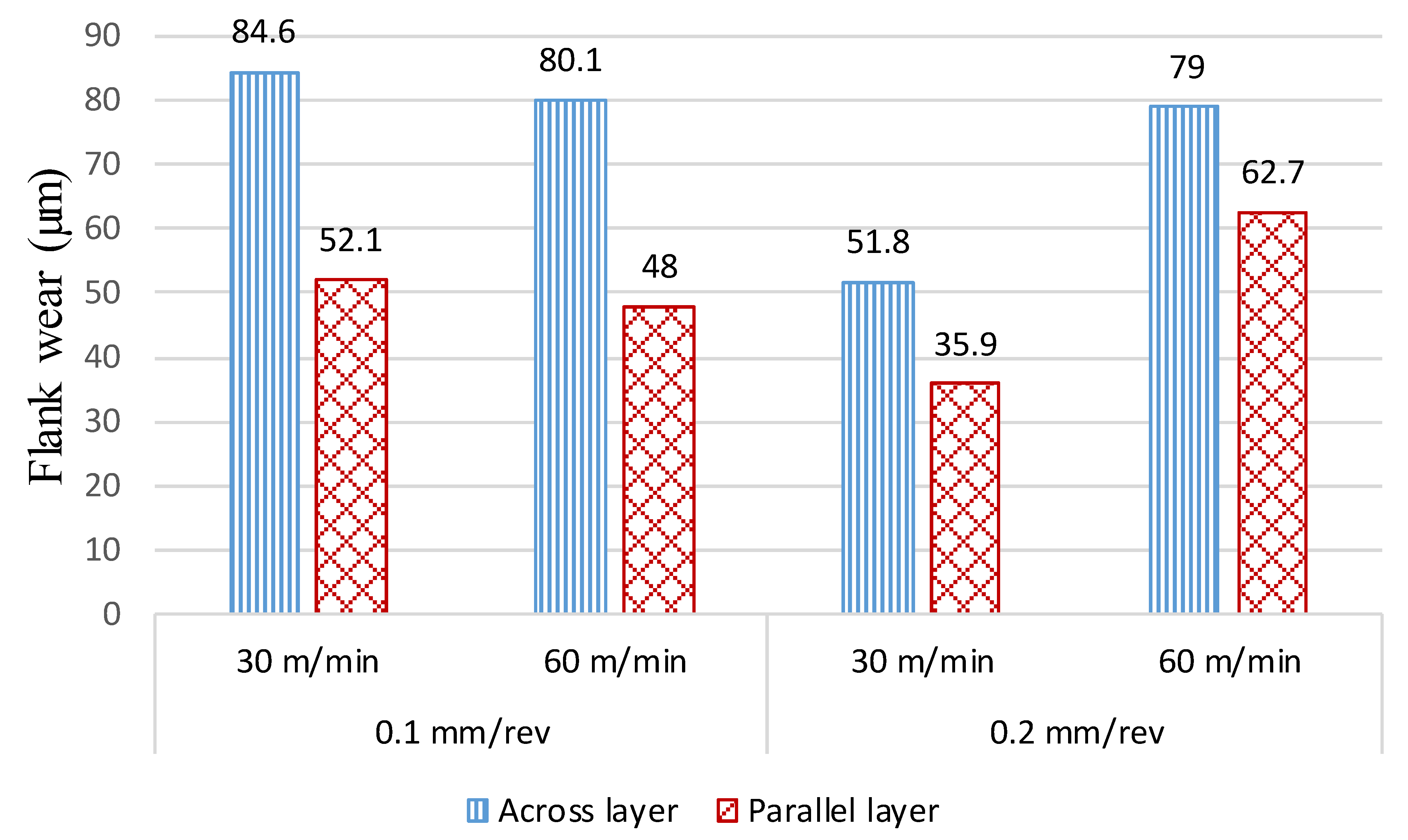
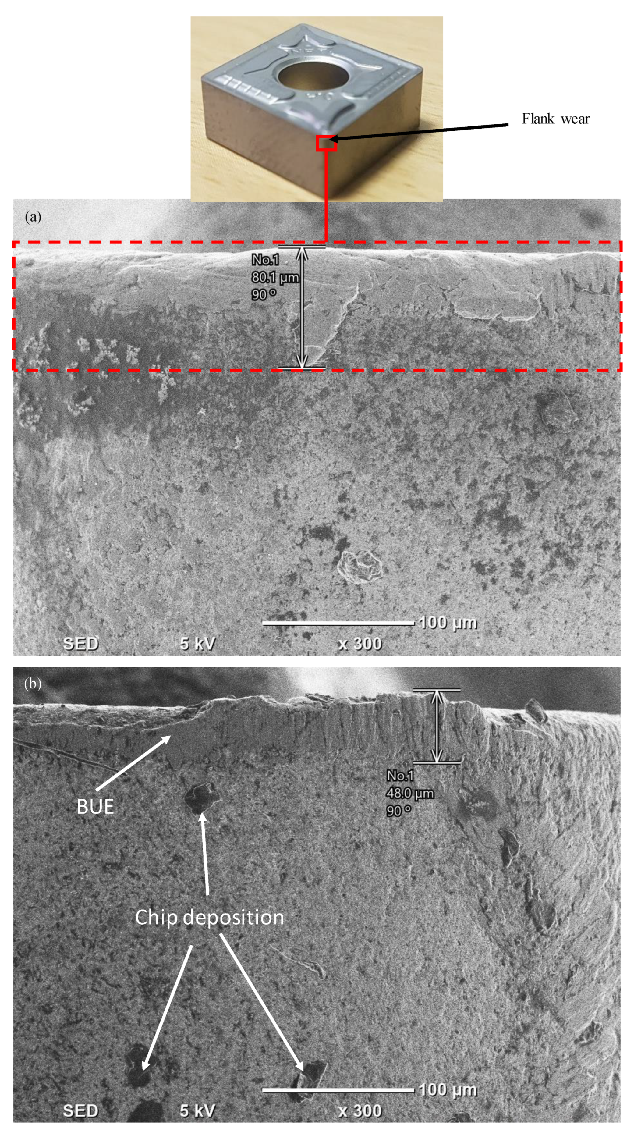
Figure 10 shows the significant difference of 23% in the average of ten chip thickness readings taken for the two-part orientations. As shown in Figure 11, the two-part orientations have a noticeable difference in the degree of the serrations on the chips, which is consistent with those found by [29]. This occurs because the EBM layers inside the chip give varying chip bending and curling resistances. Figure 11a shows substantially larger saw-tooth chips for AL orientation due to the increased thickness resulting in greater power consumption. Although the AL orientation generates more saw tooth chips, it produces an enhanced surface. Due to the shearing and tensile stresses on the layer interfaces, the degree of the serrations on the chips is lower in the case of PL orientations, as shown in Figure 11b. It is easy to spot that the chips produced as a result of turning in the AL orientation possess distinctive saw-toothed morphology (more serrated). In contrast, more rounded-toothed chips were produced in the case of PL orientation. The reason for this is that the machining is implemented in such a way that the collective impact of the cutting force, feed force, and part orientation on the interfaces of the layers resulted in variable chip formation. It is worth mentioning that, in most circumstances, the Ti6Al4V alloy shows serrated chips [49,50], as produced in the case of AL orientation. Therefore, it looks like an unnatural machining response is presented by Ti6Al4V while machined along the PL orientation.

3.4. Flank Wear

The flank wear for both orientations at a variety of turning parameters (cutting speed (V) and feed rate (f)) is displayed in Figure 12. There is a considerable difference between the two orientations, with the AL orientation having a higher value than the PL orientation for all turning parameters. In Figure 12, at a speed of 60 m/min and feed rate of 0.1 mm/rev, the maximum difference between the flank wear in AL orientation and the flank wear in PL orientation is approximately 40%. Figure 13 shows the morphology (wear) on the flank faces for both orientations, as assessed via SEM images, and shows the flank wear for both inserts. In Figure 13a, a maximum flank wear of 80.1 μm was detected in the case of AL orientation. At the same time, a maximum flank wear of 48 μm was detected in the PL orientation, as shown in Figure 13b. This was ascribed to the higher cutting force experienced during turning in the AL orientation as compared to [29,31], which can be explained by the schematic view in Figure 7a and the thicker chip load, as shown in Figure 13a.

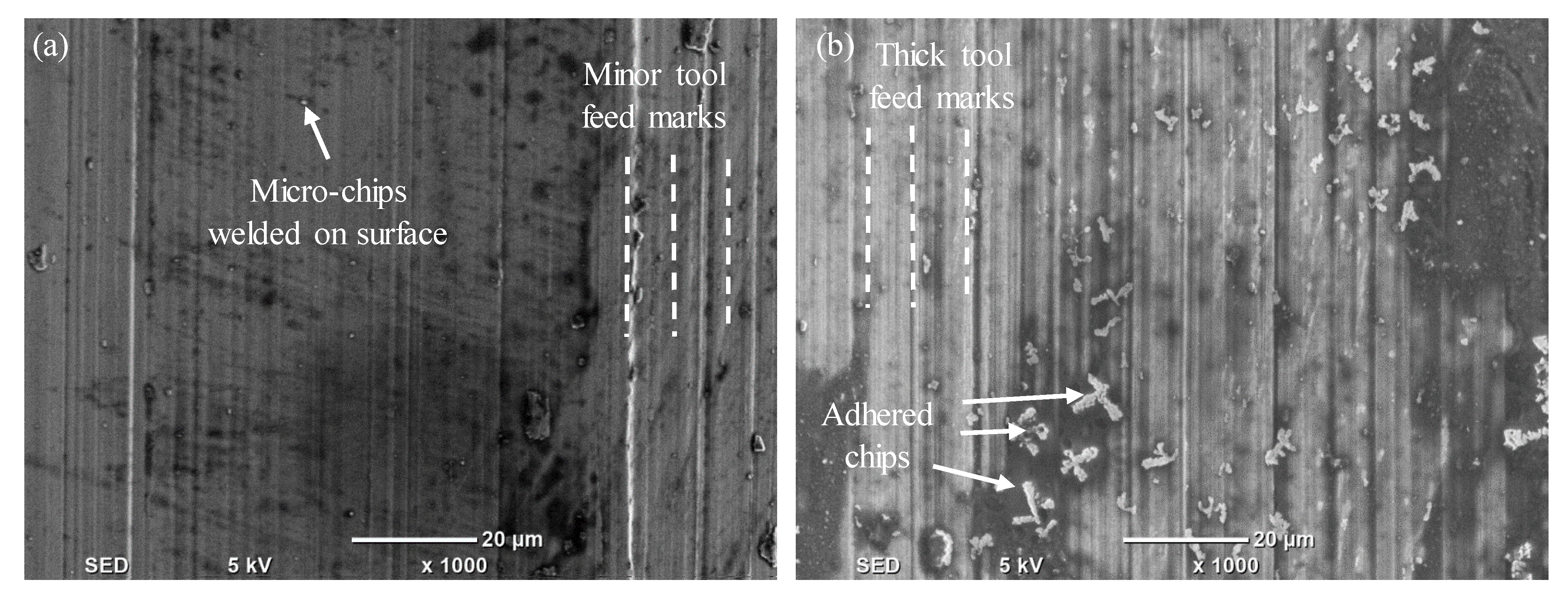
3.5. Surface Morphology

The EBM component’s surface morphology after the turning process for the two-part orientations is shown in SEM images in Figure 14 and Figure 15. The acquired SEM images for AL and PL orientations are clearly distinguishable in terms of chip adhesion and tool feed marks on the machined surfaces, as reported by [29,30]. The interfaces between the consecutive layers in an AL orientation are perpendicular to the direction of the tool feed. As shown in Figure 12a and Figure 13a at various cutting speeds, the tool forces and stress distributions were consequently more uniform, causing a smoother surface texture after turning. Additionally, it is noted that the turned surface shows no signs of chips adhering to the machined surface.
In the instance of PL orientation (see Figure 14b and Figure 15b), thicker feed marks are generated, resulting in a rougher surface after turning than in the case of AL orientation. When the EBM components are machined in a PL orientation, the adhesion of the microchips to the machined surface increases significantly. This is due to the buckling and shear stresses on the layers’ interfaces; the workpiece material/chips undergo an earlier fracture, creating chip deposition on the machined surface. Additionally, the tiny prematurely fractured chips are deposited on the tool cutting edges (forming a BUE), as evident in Figure 15b, leading to aggressive tool feed marks on the machined surface and deteriorated surface roughness. Figure 14b and Figure 15b show clear evidence of chip adhesion and thicker feed marks on the machined surface, which decreases the surface quality of the Ti6Al4V EBM component. This indicates that the parallel layer orientation is inappropriate for surface improvement during machining compared to the AL orientation.

4. Conclusions

This research presents an investigation for improving the surface quality of Ti6Al4V components manufactured by electron beam melting (EBM) by considering the influence of part orientations during the turning process. In this study, the machinability of Ti6Al4V EBM parts was studied in terms of surface roughness, power consumption, chip morphology, flank tool wear, and surface morphology. It was observed that EBM parts with varied component orientations exhibited varying machining performances depending on the layers’ orientations despite using the same cutting parameters. The following main conclusions could be drawn from the results.
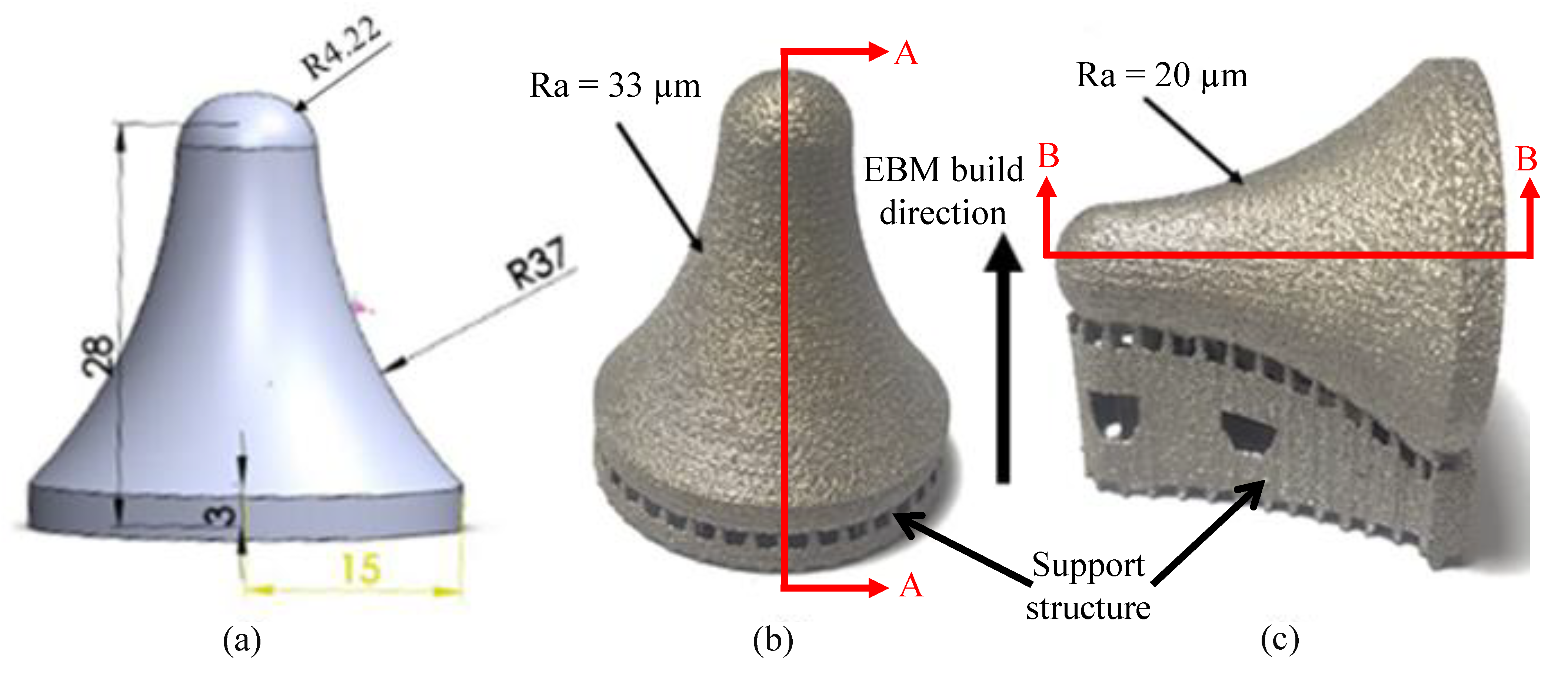
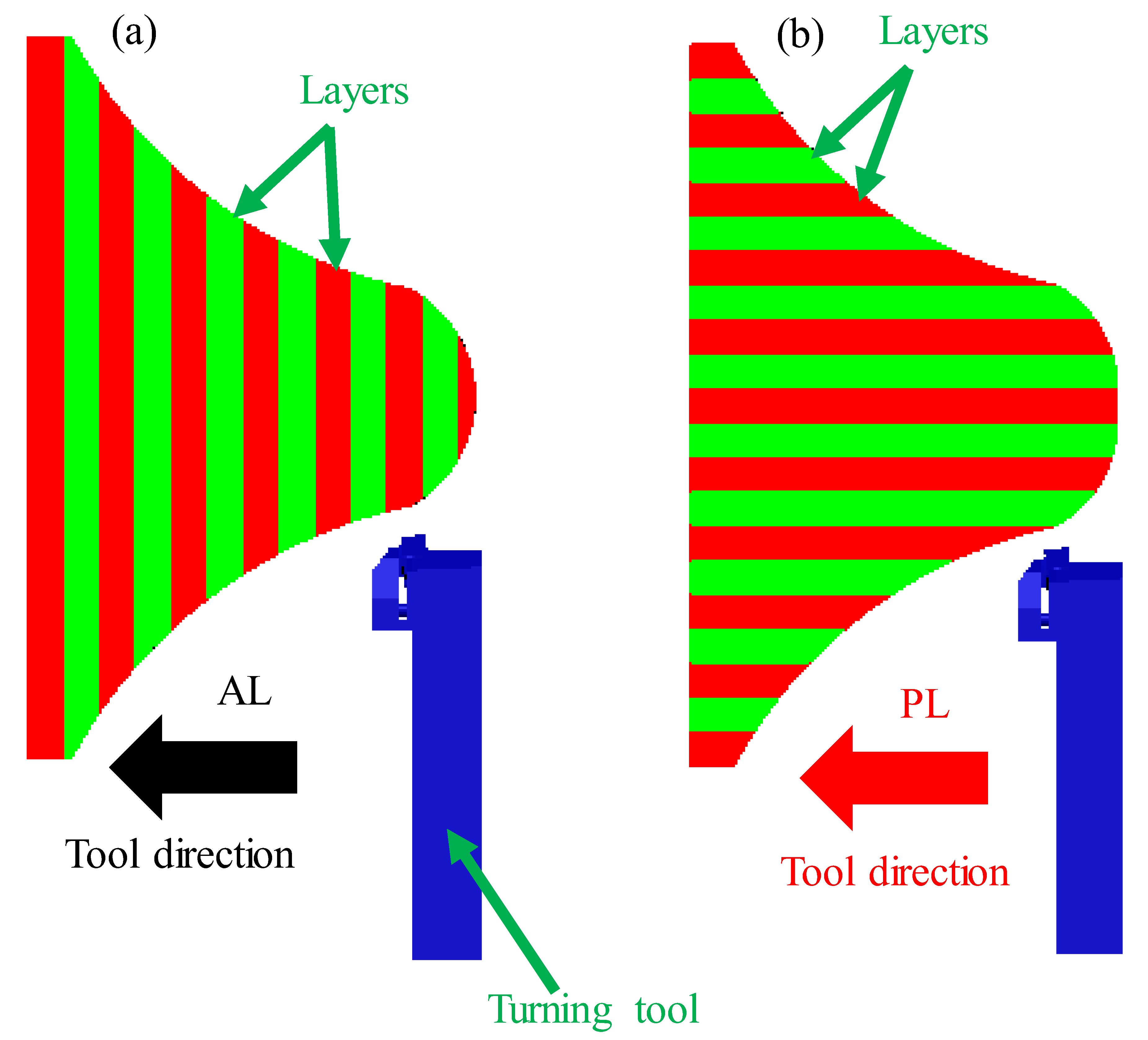
  • EBM Ti6Al4V components revealed significantly higher surface roughness values for the parts printed along the AL (Ra = 33 µm) and PL (Ra = 20 µm) orientations, even when utilizing optimal ARCAM-suggested process parameters;
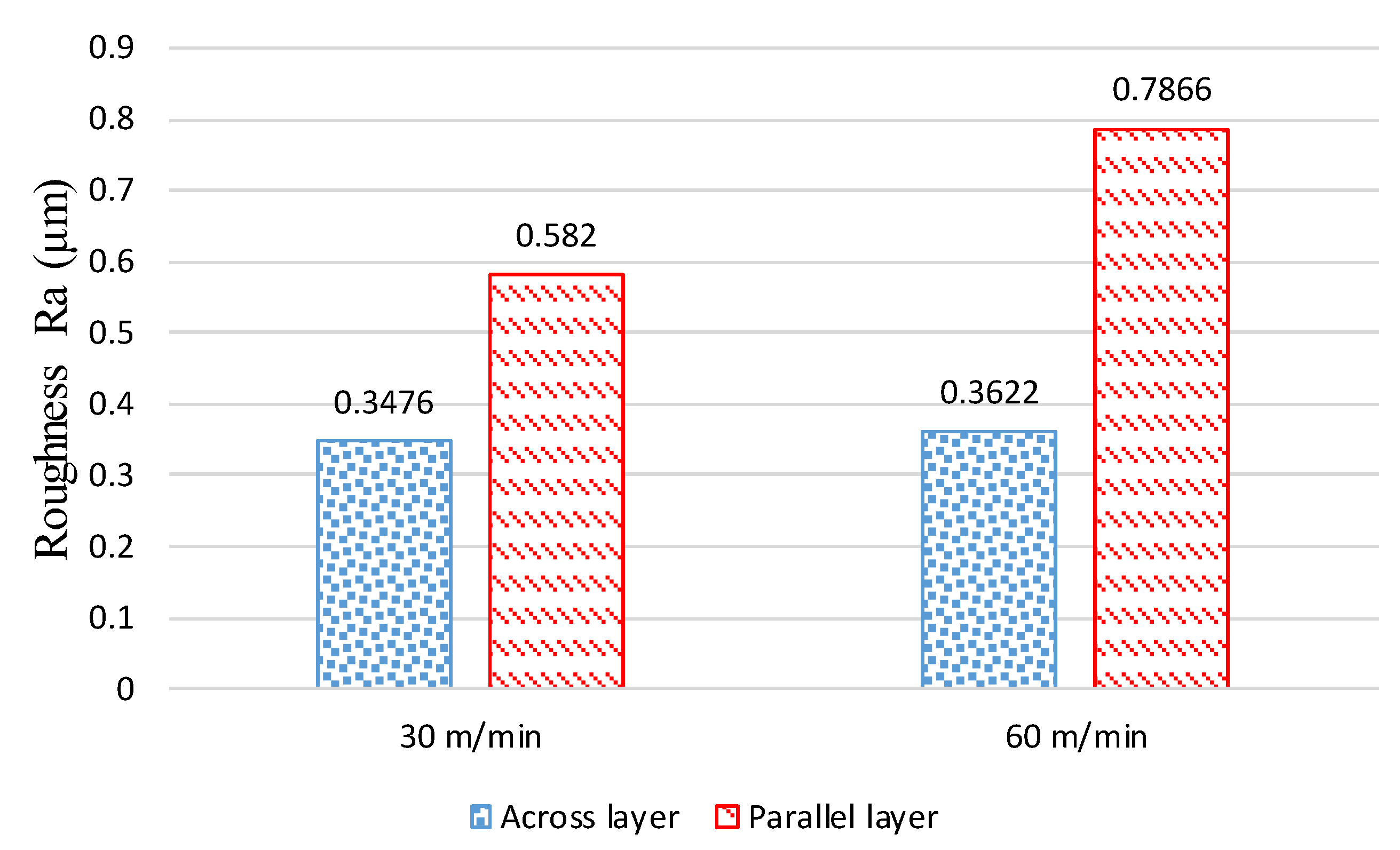
  • A maximum of 54% difference was observed between the achieved roughness after turning along the PL and AL orientations. Furthermore, the surface roughness for AL orientation (Ra = 0.35 µm) was significantly reduced (improved) compared to the PL orientations (Ra = 0.79 µm). This is mostly because of the influence of the EBM layers’ orientations;
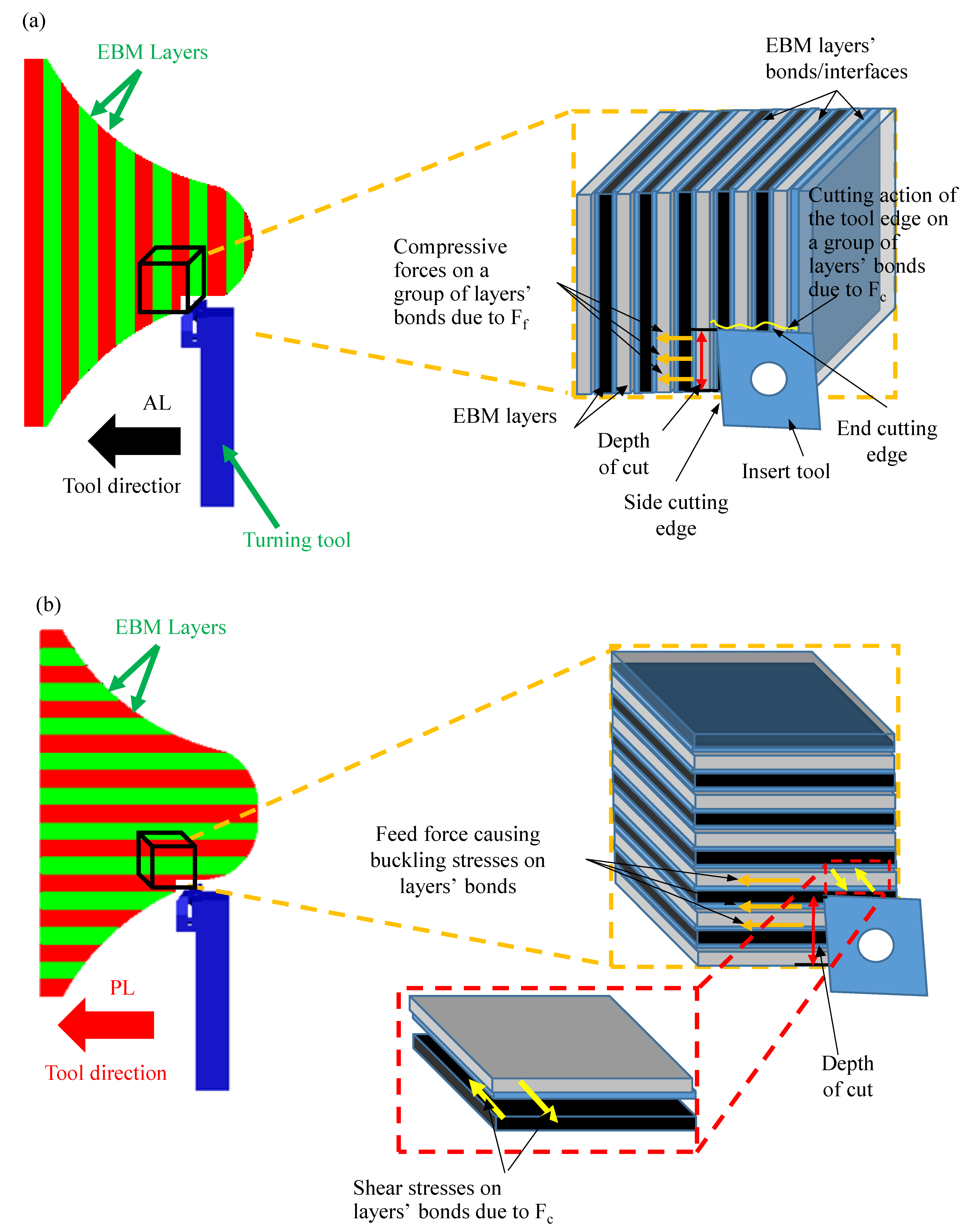
  • The AL orientation showed a higher power consumption compared to the PL orientation. For instance, with the same turning parameters of V = 60 m/min, f = 0.1 mm/rev, and d = 0.2 mm, the power in the case of AL orientation was 8.96 kW, 19% higher than for PL orientations;
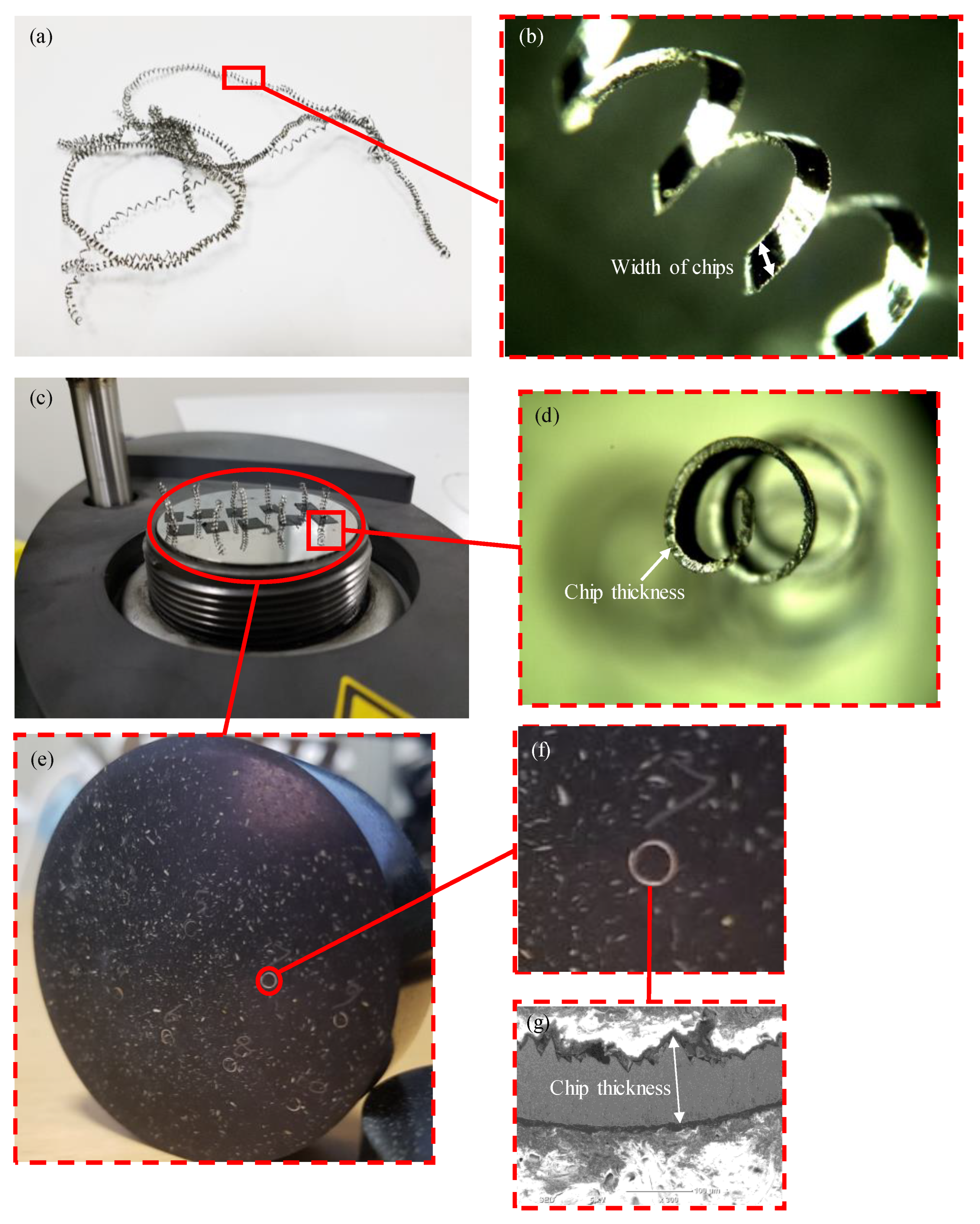
  • In terms of chip morphology, AL orientation showed a higher degree of serrated saw tooth chips and thicker chips than PL orientation;
  • It was observed that flank wear varies depending on the orientations of the component. AL orientation showed a high degree of flank wear but no built-up edge, while the insert used for PL orientation showed higher flank wear with BUE formation;
  • The surface morphology of the turned parts revealed microchip deposition and thick tool feed marks for the PL orientation compared to a smoother morphology for the AL orientation;
  • Overall, the results indicated that a superior surface finish and integrity can be attained for the Ti6Al4V EBM parts machined along the AL orientation;
  • Work needs to be conducted regarding the fatigue life of the EBM samples machined across different orientations. Additionally, the accuracy of the machined parts needs to be studied for various orientations;
  • Finite element analysis (FEA) should be conducted for the machining of the EBM parts while considering the bonding strength between the layers and the microstructural directional effects.

Author Contributions

Conceptualization, A.D. and S.A.; methodology, A.D., W.A., M.M.N. and H.K.; validation, A.D. and S.A.; formal analysis, S.A., A.D. and K.N.A.; investigation, A.D. and S.A.; data curation, A.D., M.M.N., H.K. and K.N.A.; writing—original draft preparation, A.D.; writing—review and editing, S.A. and A.M.A.-S.; visualization, A.D. and S.A.; supervision, S.A. and A.M.A.-S.; resources, W.A, S.A. and A.M.A.-S. All authors have read and agreed to the published version of the manuscript.

Funding

Researchers Supporting Project number (RSPD2023R702), King Saud University, Riyadh, Saudi Arabia.

Institutional Review Board Statement

Not applicable.

Informed Consent Statement

Not applicable.

Data Availability Statement

All data generated or analyzed during this study are included in the present article.

Acknowledgments

The authors appreciate the support from Researchers Supporting Project number (RSPD2023R702), King Saud University, Riyadh, Saudi Arabia.

Conflicts of Interest

The authors declare no conflict of interest.

References

  1. Chen, Q.; Thouas, G.A. Metallic Implant Biomaterials. Mater. Sci. Eng. R Rep. 2015, 87, 1–57. [Google Scholar] [CrossRef]
  2. Sun, Y.; Huang, B.; Puleo, D.A.; Schoop, J.; Jawahir, I.S. Improved Surface Integrity from Cryogenic Machining of Ti-6Al-7Nb Alloy for Biomedical Applications. Procedia CIRP 2016, 45, 63–66. [Google Scholar] [CrossRef] [Green Version]
  3. Stadlinger, B.; Ferguson, S.J.; Eckelt, U.; Mai, R.; Lode, A.T.; Loukota, R.; Schlottig, F. Biomechanical Evaluation of a Titanium Implant Surface Conditioned by a Hydroxide Ion Solution. Br. J. Oral Maxillofac. Surg. 2012, 50, 74–79. [Google Scholar] [CrossRef] [PubMed]
  4. Ezugwu, E.O.; Wang, Z.M. Titanium Alloys and Their Machinability—A Review. J. Mater. Process. Technol. 1997, 68, 262–274. [Google Scholar] [CrossRef]
  5. Kaur, M.; Singh, K. Review on Titanium and Titanium Based Alloys as Biomaterials for Orthopaedic Applications. Mater. Sci. Eng. C 2019, 102, 844–862. [Google Scholar] [CrossRef] [PubMed]
  6. Khorasani, A.M.; Goldberg, M.; Doeven, E.H.; Littlefair, G. Titanium in Biomedical Applications—Properties and Fabrication: A Review. J. Biomater. Tissue Eng. 2015, 5, 593–619. [Google Scholar] [CrossRef]
  7. Kunčická, L.; Kocich, R.; Lowe, T.C. Advances in Metals and Alloys for Joint Replacement. Prog. Mater. Sci. 2017, 88, 232–280. [Google Scholar] [CrossRef]
  8. Airao, J.; Nirala, C.K.; Bertolini, R.; Krolczyk, G.M.; Khanna, N. Sustainable Cooling Strategies to Reduce Tool Wear, Power Consumption and Surface Roughness during Ultrasonic Assisted Turning of Ti-6Al-4V. Tribol. Int. 2022, 169, 107494. [Google Scholar] [CrossRef]
  9. Zhang, L.C.; Liu, Y.; Li, S.; Hao, Y. Additive Manufacturing of Titanium Alloys by Electron Beam Melting: A Review. Adv. Eng. Mater. 2018, 20, 1700842. [Google Scholar] [CrossRef]
  10. Bertolini, R.; Lizzul, L.; Pezzato, L.; Ghiotti, A.; Bruschi, S. Improving Surface Integrity and Corrosion Resistance of Additive Manufactured Ti6Al4V Alloy by Cryogenic Machining. Int. J. Adv. Manuf. Technol. 2019, 104, 2839–2850. [Google Scholar] [CrossRef]
  11. Mallipeddi, D.; Hajali, T.; Rännar, L.E.; Bergström, A.; Hernandez, S.; Strandh, E.; Nyborg, L.; Krajnik, P. Surface Integrity of Machined Electron Beam Melted Ti6Al4V Alloy Manufactured with Different Contour Settings and Heat Treatment. Procedia CIRP 2020, 87, 327–332. [Google Scholar] [CrossRef]
  12. Safdar, A.; He, H.Z.; Wei, L.-Y.; Snis, A.; Chavez de Paz, L.E. Effect of Process Parameters Settings and Thickness on Surface Roughness of EBM Produced Ti-6Al-4V. Rapid Prototyp. J. 2012, 18, 401–408. [Google Scholar] [CrossRef]
  13. Razavi, S.M.J.; Van Hooreweder, B.; Berto, F. Effect of Build Thickness and Geometry on Quasi-Static and Fatigue Behavior of Ti-6Al-4V Produced by Electron Beam Melting. Addit. Manuf. 2020, 36, 101426. [Google Scholar] [CrossRef]
  14. Abdeen, D.H.; Palmer, B.R. Effect of Processing Parameters of Electron Beam Melting Machine on Properties of Ti-6Al-4V Parts. Rapid Prototyp. J. 2016, 22, 609–620. [Google Scholar] [CrossRef]
  15. Galati, M.; Minetola, P.; Rizza, G. Surface Roughness Characterisation and Analysis of the Electron Beam Melting (EBM) Process. Materials 2019, 12, 2211. [Google Scholar] [CrossRef] [PubMed] [Green Version]
  16. Galati, M.; Iuliano, L. A Literature Review of Powder-Based Electron Beam Melting Focusing on Numerical Simulations. Addit. Manuf. 2018, 19, 1–20. [Google Scholar] [CrossRef]
  17. Wang, P.; Sin, W.J.; Nai, M.L.S.; Wei, J. Effects of Processing Parameters on Surface Roughness of Additive Manufactured Ti-6Al-4V via Electron Beam Melting. Materials 2017, 10, 1121. [Google Scholar] [CrossRef] [Green Version]
  18. Mohammad, A.; Al-Ahmari, A.; Alfaify, A.; Khan Mohammed, M.; Mushabab Al-Ahmari, A.; AlFaify, A. Effect of Melt Parameters on Density and Surface Roughness in Electron Beam Melting of Gamma Titanium Aluminide Alloy Modelling and Optimization While Machining Particle Reinforced Alumina Based Metal Matrix Composites View Project Development and Evaluation of Virtual Manufacturing Assembly Simulation System (VMASS) View Project Rapid Prototyping Journal Effect of Melt Parameters on Density and Surface Roughness in Electron Beam Melting of Gamma Titanium Aluminide Alloy Article Information. Artic. Rapid Prototyp. J. 2017, 23, 474–485. [Google Scholar] [CrossRef]
  19. Al-Bermani, S.S.; Blackmore, M.L.; Zhang, W.; Todd, I. The Origin of Microstructural Diversity, Texture, and Mechanical Properties in Electron Beam Melted Ti-6Al-4V. Metall. Mater. Trans. A Phys. Metall. Mater. Sci. 2010, 41, 3422–3434. [Google Scholar] [CrossRef]
  20. The Importance of Surface Finish in Components for The Aerospace and Medical Industries. Available online: https://www.slideshare.net/nuclead/the-importance-of-surface-finish-in-components-for-the-aerospace-and-medical-industries (accessed on 21 September 2020).
  21. Galanis, N.I.; Manolakos, D.E. Surface Roughness of Manufactured Femoral Heads with High Speed Turning. Int. J. Mach. Mach. Mater. 2009, 5, 371–382. [Google Scholar] [CrossRef]
  22. Bertolini, R.; Lizzul, L.; Bruschi, S.; Ghiotti, A. On the Surface Integrity of Electron Beam Melted Ti6Al4V after Machining. Procedia CIRP 2019, 82, 326–331. [Google Scholar] [CrossRef]
  23. Bordin, A.; Bruschi, S.; Ghiotti, A.; Bucciotti, F.; Facchini, L. Comparison between Wrought and EBM Ti6Al4V Machinability Characteristics. Key Eng. Mater. 2014, 611–612, 1186–1193. [Google Scholar] [CrossRef]
  24. Le Coz, G.; Fischer, M.; Piquard, R.; D’Acunto, A.; Laheurte, P.; Dudzinski, D. Micro Cutting of Ti-6Al-4V Parts Produced by SLM Process. Procedia CIRP 2017, 58, 228–232. [Google Scholar] [CrossRef]
  25. Li, G.; Rashid, R.A.R.; Ding, S.; Sun, S.; Palanisamy, S. Machinability Analysis of Finish-Turning Operations for Ti6Al4V Tubes Fabricated by Selective Laser Melting. Metals 2022, 12, 806. [Google Scholar] [CrossRef]
  26. Sartori, S.; Bordin, A.; Bruschi, S.; Ghiotti, A. Machinability of the EBM Ti6Al4V in Cryogenic Turning. Key Eng. Mater. 2015, 651–653, 1183–1188. [Google Scholar] [CrossRef]
  27. Anwar, S.; Ahmed, N.; Pervaiz, S.; Ahmad, S.; Mohammad, A.; Saleh, M. On the Turning of Electron Beam Melted Gamma-TiAl with Coated and Uncoated Tools: A Machinability Analysis. J. Mater. Process. Technol. 2020, 282, 116664. [Google Scholar] [CrossRef]
  28. Anwar, S.; Ahmed, N.; Abdo, B.M.; Pervaiz, S.; Chowdhury, M.A.K.; Alahmari, A.M. Electron Beam Melting of Gamma Titanium Aluminide and Investigating the Effect of EBM Layer Orientation on Milling Performance. Int. J. Adv. Manuf. Technol. 2018, 96, 3093–3107. [Google Scholar] [CrossRef]
  29. Dabwan, A.; Anwar, S.; Al-Samhan, A.; Nasr, M. On the Effect of Electron Beam Melted Ti6Al4V Part Orientations during Milling. Metals 2020, 10, 1172. [Google Scholar] [CrossRef]
  30. Dabwan, A.; Anwar, S.; Al-Samhan, A.M.; Nasr, M.M.; AlFaify, A. On the Influence of Heat Treatment in Suppressing the Layer Orientation Effect in Finishing of Electron Beam Melted Ti6Al4V. Int. J. Adv. Manuf. Technol. 2022, 118, 3035–3048. [Google Scholar] [CrossRef]
  31. Dabwan, A.; Anwar, S.; Al-Samhan, A.M.; AlFaify, A.; Nasr, M.M. Investigations on the Effect of Layers’ Thickness and Orientations in the Machining of Additively Manufactured Stainless Steel 316L. Materials 2021, 14, 1797. [Google Scholar] [CrossRef]
  32. Lizzul, L.; Bertolini, R.; Ghiotti, A.; Bruschi, S. Turning of Additively Manufactured Ti6al4v: Effect of the Highly Oriented Microstructure on the Surface Integrity. Materials 2021, 14, 2842. [Google Scholar] [CrossRef] [PubMed]
  33. Ameen, W.; Al-Ahmari, A.; Mohammed, M.K. Self-Supporting Overhang Structures Produced by Additive Manufacturing through Electron Beam Melting. Int. J. Adv. Manuf. Technol. 2019, 104, 2215–2232. [Google Scholar] [CrossRef]
  34. Umer, U.; Ameen, W.; Abidi, M.H.; Moiduddin, K.; Alkhalefah, H.; Alkahtani, M.; Al-Ahmari, A. Modeling the Effect of Different Support Structures in Electron Beam Melting of Titanium Alloy Using Finite Element Models. Metals 2019, 9, 806. [Google Scholar] [CrossRef] [Green Version]
  35. Ameen, W.; Al-Ahmari, A.; Mohammed, M.K.; Abdulhameed, O.; Umer, U.; Moiduddin, K. Design, Finite Element Analysis (FEA), and Fabrication of Custom Titanium Alloy Cranial Implant Using Electron Beam Melting Additive Manufacturing. Adv. Prod. Eng. Manag. 2018, 13, 267–278. [Google Scholar] [CrossRef] [Green Version]
  36. Bordin, A.; Sartori, S.; Bruschi, S.; Ghiotti, A. Experimental Investigation on the Feasibility of Dry and Cryogenic Machining as Sustainable Strategies When Turning Ti6Al4V Produced by Additive Manufacturing. J. Clean. Prod. 2017, 142, 4142–4151. [Google Scholar] [CrossRef]
  37. Bruschi, S.; Bertolini, R.; Bordin, A.; Medea, F.; Ghiotti, A. Influence of the Machining Parameters and Cooling Strategies on the Wear Behavior of Wrought and Additive Manufactured Ti6Al4V for Biomedical Applications. Tribol. Int. 2016, 102, 133–142. [Google Scholar] [CrossRef]
  38. Hıs¸man, Y.; Çelik, H.; Kilickap, E.; Güney, M. Investigation of Cutting Parameters Affecting on Tool Wear and Surface Roughness in Dry Turning of Ti-6Al-4V Using CVD and PVD Coated Tools. J. Braz. Soc. Mech. Sci. Eng. 2017, 39, 2085–2093. [Google Scholar] [CrossRef]
  39. Pervaiz, S.; Deiab, I.; Darras, B. Power Consumption and Tool Wear Assessment When Machining Titanium Alloys. Int. J. Precis. Eng. Manuf. 2013, 14, 925. [Google Scholar] [CrossRef]
  40. Al-Ghamdi, K.A.; Iqbal, A. A Sustainability Comparison between Conventional and High-Speed Machining. J. Clean. Prod. 2015, 108, 192–206. [Google Scholar] [CrossRef]
  41. Abdo, B.M.A.; El-Tamimi, A.M.; Anwar, S.; Umer, U.; Alahmari, A.M.; Ghaleb, M.A. Experimental Investigation and Multi-Objective Optimization of Nd:YAG Laser Micro-Channeling Process of Zirconia Dental Ceramic. Int. J. Adv. Manuf. Technol. 2018, 98, 2213–2230. [Google Scholar] [CrossRef]
  42. Dambhare, S.; Deshmukh, S.; Borade, A.; Digalwar, A.; Phate, M. Sustainability Issues in Turning Process: A Study in Indian Machining Industry. Procedia CIRP 2015, 26, 379–384. [Google Scholar] [CrossRef] [Green Version]
  43. Syam, I.; Fitriadi, N.; Lindawati; Mukhsan; Isma. A Performance of Power System Installation Tool Kits Electricity 1 ɸ and 3 ɸ As Practicum Kits at the Power Electronics Laboratory. J. Inotera 2020, 5, 120–128. [Google Scholar] [CrossRef]
  44. Chijioke, J.; Uju, I.U.; Atuchukwu, J. A Automatic Power Factor Correction for Variable Inductive Load Industries: A Case Study of Resources Improvement and Manufacturing Company Ltd. (Rimco). Iconic Res. Eng. J. 2019, 3, 1–8. Available online: https://www.researchgate.net/profile/John-Atuchukwu/publication/343833481_Automatic_Power_Factor_Correction_for_Variable_Inductive_Load_Industries_A_Case_Study_of_Resources_Improvement_and_Manufacturing_Company_Ltd_Rimco/links/5f43c5fea6fdcccc43f5864b/Automatic-Power-Factor-Correction-for-Variable-Inductive-Load-Industries-A-Case-Study-of-Resources-Improvement-and-Manufacturing-Company-Ltd-Rimco.pdf (accessed on 6 March 2023).
  45. Bhuiyan, M.S.H.; Choudhury, I.A.; Dahari, M. Monitoring the Tool Wear, Surface Roughness and Chip Formation Occurrences Using Multiple Sensors in Turning. J. Manuf. Syst. 2014, 33, 476–487. [Google Scholar] [CrossRef]
  46. Maruda, R.W.; Krolczyk, G.M.; Niesłony, P.; Krolczyk, J.B.; Legutko, S. Chip Formation Zone Analysis during the Turning of Austenitic Stainless Steel 316L under MQCL Cooling Condition. Procedia Eng. 2016, 149, 297–304. [Google Scholar] [CrossRef] [Green Version]
  47. Kumar, M.; Kumar, A.; Ji, H.; Song, Q.; Liu, Z.; Cai, W.; Mia, M.; Khanna, N. Impact of Layer Rotation on Micro-Structure, Grain Size, Surface Integrity and Mechanical Behaviour of SLM Al-Si-10Mg Alloy. Integr. Med. Res. 2020, 9, 9506–9522. [Google Scholar] [CrossRef]
  48. Airao, J.; Nirala, C.K. Machinability of Ti-6Al-4V and Nimonic-90 in Ultrasonic-Assisted Turning under Sustainable Cutting Fluid. Mater. Today Proc. 2022, 62, 7396–7400. [Google Scholar] [CrossRef]
  49. Outeiro, J.; Cheng, W.; Chinesta, F.; Ammar, A. Modelling and Optimization of Machining of Ti-6Al-4V Titanium Alloy Using Machine Learning and Design of Experiments Methods. J. Manuf. Mater. Process. 2022, 6, 58. [Google Scholar] [CrossRef]
  50. Wang, B.; Liu, Z. Evaluation on Fracture Locus of Serrated Chip Generation with Stress Triaxiality in High Speed Machining of Ti6Al4V. Mater. Des. 2016, 98, 68–78. [Google Scholar] [CrossRef]
Figure 1. Non-prismatic part: (a) designed part; (b) a typical EBM part fabricated with across-layers orientation, (c) a typical EBM part fabricated with parallel layers orientation (Cross sections AA’ and BB’ used later.).
Processes 11 01031 g001
Figure 2. A simplified illustration of the various part orientations possible while turning an EBM: (a) across Layer (AL); (b) parallel Layer (PL).
Processes 11 01031 g002
Figure 3. Dry machining process setup for non-prismatic component produced by EBM: (a) turning process setup; (b) enlarged view of a machined part; and (c) enlarged view of insert tool.
Processes 11 01031 g003
Figure 4. Steps of preparation for the chips to be measured by SEM.
Processes 11 01031 g004
Figure 5. Surface roughness measured for AL and PL orientations at V = 30 and 60 m/min, f = 0.1 mm/rev, and d = 0.2 mm.
Processes 11 01031 g005
Figure 6. Two-dimensional roughness profiles at V = 30 m/min and f = 0.1 mm/rev for (a) AL orientations and (b) PL orientations.
Processes 11 01031 g006
Figure 7. Schematic view of the effect of the cutting and feed forces during the turning process as (a) shear and compressive forces in across layers and as (b) tensile and buckling forces in the case of parallel layers.
Processes 11 01031 g007
Figure 8. Microstructural images of the cross-sections shown in Figure 1 for the EBM Ti6Al4V part: (a) cross-section AA’; (b) cross-section BB’.
Processes 11 01031 g008
Figure 9. Power consumption recorded during the machining for AL and PL orientations at V = 30 and 60 m/min, and d = 0.2 mm at (a) f = 0.1 mm/rev and (b) f = 0.2 mm/rev.
Processes 11 01031 g009
Figure 10. Chips’ thickness measured for AL and PL orientations at f = 0.1 mm/rev, V = 60 m/min, and d = 0.2 mm.
Processes 11 01031 g010
Figure 11. Chip morphology for the two orientations: (a) AL orientation and (b) PL orientation at f = 0.1 mm/rev, V = 60 m/min, and d = 0.2 mm.
Processes 11 01031 g011
Figure 12. Flank wear measured for AL orientation and PL orientation at V = 30 m/min and 60 m/min, f = 0.1 mm/rev and 0.2 mm/rev, and d = 0.2 mm.
Processes 11 01031 g012
Figure 13. Flank wear for the two orientations: (a) AL orientation and (b) PL orientation at f = 0.1 mm/rev, V = 60 m/min, and d = 0.2 mm.
Processes 11 01031 g013
Figure 14. Turned surface images for the two orientations using SEM: (a) AL orientation and (b) PL orientation at V = 30 m/min, f = 0.1 mm/rev, and d = 0.2 mm.
Processes 11 01031 g014
Figure 15. Turned surface images for the two orientations using SEM: (a) AL orientation and (b) PL orientation at V = 60 m/min, f = 0.1 mm/rev, and d = 0.2 mm.
Processes 11 01031 g015
Table 1. Chemical composition of powdered Ti6Al4V [35].
Element%
Al6.04
V4.05
C0.013
Fe0.0107
O0.13
TiBalance/Base
Table 2. Parameters for EBM processing of Ti6Al4V components [33,34].
Parameters of EBMValues
Powder layer thickness0.05 mm
Preheat temperature750 °C
Electron beam diameter200 μm
Scan speed4530 mm/s
Beam current15 mA
Acceleration voltage60 kV
Line offset0.1 Mm
Solidus temperature1878 K
Focus offset3 mA
Liquidus temperature1928 K
Table 3. Turning process parameters.
Process ParametersSymbolsUnitsValues
Feed ratefmm/rev0.1, 0.2
Depth of cutdmm0.2
Cutting speedVm/min30, 60
Part/layers orientation--AL, PL
Disclaimer/Publisher’s Note: The statements, opinions and data contained in all publications are solely those of the individual author(s) and contributor(s) and not of MDPI and/or the editor(s). MDPI and/or the editor(s) disclaim responsibility for any injury to people or property resulting from any ideas, methods, instructions or products referred to in the content.

