
Mechanical Behavior of Gas-Transmission Pipeline in a Goaf

1
College of Geophysics and Oil Resources, Yangtze University, Wuhan 430100, China
2
Key Laboratory of Exploration Technologies for Oil and Gas Resources, Ministry of Education, Yangtze University, Wuhan 430100, China
3
School of Petroleum Engineering, Yangtze University, Wuhan 430100, China
4
Key Laboratory of Drilling and Production Engineering for Oil and Gas, Wuhan 430100, China
5
College of Pipeline and Civil Engineering, China University of Petroleum (East China), Qingdao 266580, China
*
Author to whom correspondence should be addressed.
Processes 2023, 11(4), 1022; https://doi.org/10.3390/pr11041022
Submission received: 24 February 2023
/
Revised: 18 March 2023
/
Accepted: 24 March 2023
/
Published: 28 March 2023
(This article belongs to the Topic Multi-Phase Flow and Unconventional Oil/Gas Development)
Abstract
:To solve the safety hazard of a buried gas pipeline caused by subsidence of a mined-out area, a three-dimensional model of a buried pipeline in a mined-out area was established using geological parameters and the finite-element software ABAQUS. The effects of the friction coefficient of the pipe and soil, the coal-seam dip angle, and the horizontal angle on the mechanical behavior of the pipe under varying widths of goaf area were investigated. The results indicate that the maximum equivalent stress of the pipeline is negatively correlated with the horizontal angle. Concerning longitudinal mining, the pipeline exhibits a high-stress zone when the mining length is >200 m, the surface displacement appears in a small range when the mining length is 40 m, and the stratum displacement range increases gradually with the increase in the mining length. When the width of the goaf is constant, the maximum equivalent stress of the pipeline is positively correlated with the tube-soil friction coefficient and negatively correlated with the coal seam dip angle. The position of maximum stress gradually tends to appear near the uphill side of the coal seam, with an increase in the coal seam dip angle.
1. Introduction
The pipeline used in the West-East Gas Transmission Project is the longest gas transmission pipeline in China, and it runs from east to west through nine provinces and regions: Xinjiang, Gansu, Ningxia, Shaanxi, Shanxi, Henan, Anhui, Jiangsu, and Shanghai. A total of 93.6% of China’s coal resources are distributed in 18 provinces, north of the Kunlun Mountains, Qinling Mountains, and Dabie Mountains. Coal mining causes the soil surface to collapse. Currently, the stress of the pipeline passing through the goaf is complex, which may produce bending deformation [1,2]. The pipeline may even be fractured, causing leakage [3,4,5]. With the continuous and rapid growth of China’s demand for natural gas, the application of high-steel-grade pipelines [6,7,8] has become increasingly popular in pipeline engineering. Therefore, it is necessary to study the mechanical behavior of high-steel-grade pipelines crossing goafs.
Researchers have analyzed the stress and strain of pipelines passing through goafs. Han Bing et al. [9] used the finite-element software ABAQUS to analyze the effects of the mining depth and coal-seam thickness on the pipeline strain and proposed that a strain-based failure criterion can be used to confirm the anti-deformation ability of the pipeline. Suchowerska et al. [10] analyzed the surface settlement laws for single and multiple coal seams through numerical simulations and investigated the influence of the constitutive model of the stratum soil on the numerical results. Wang et al. [11] evaluated the law of surface movement in the area facing the slope influenced by coal mining with a physical model; they found that coal mining with multiple seams produces additional intense rock strata movement and surface failure than that of a single seam. Kalisz et al. [12] studied the influence of underground mining on surface deformation based on practical engineering and examined the causes of failure of natural-gas pipelines crossing a goaf. Xiaolin et al. [13] developed an analytical calculation method for buried pipelines in the subsidence area based on the probability integral method, providing stress–strain calculations for buried pipelines crossing the subsidence area at any angle. Hao et al. [14] used ABAQUS to analyze the effects of different mining angles on the mechanical behavior of pipelines and concluded that pipelines with an included angle of 90° were least affected by underground mining. Although experts have investigated the mechanical behavior of goaf gas pipelines, high-steel-grade pipelines passing through goafs have yet to be analyzed; thus, limited studies have been conducted on the mechanical behavior of high-steel-grade pipelines based on actual geological parameters.
Through our investigation of the literature on the research status at home and abroad, we found that other studies aimed at analyzing the mechanical behavior of low-steel-grade pipes in the goaf; however, high-steel-grade pipes under this same working condition are not analyzed as such. Due to the development of the West-East Gas Transmission Project, high-steel-grade pipes are more frequently applied in pipeline engineering, so it is highly necessary to include high-steel-grade pipes in the analysis. Due to the advantages of high-steel-grade pipelines, such as high strength, good fracture toughness, and good welding performance, the performance difference between low-steel-grade pipelines and high-steel-grade pipelines are very obvious. Additionally, the conclusions from low-steel-grade pipelines are not necessarily fully applicable to high-steel-grade pipelines. Therefore, the mechanical behavior of high-steel-grade X80 pipeline in goaf is analyzed in this paper. At present, the research on buried pipelines in goaf does not consider the influence of the spatial location of the coal seam on pipeline mechanics. Therefore, this paper analyzes the influence of the space location of the coal seam in goafs on buried pipelines.
Therefore, using actual geological parameters with ABAQUS, a three-dimensional mechanical analysis model of a buried high-steel-grade pipeline under a collapsed mined-out area was developed in this study. Our paper analyzed the effects of the horizontal mining angle, the tangential friction coefficient of the pipe and soil, and the coal-seam dip angle on the pipeline’s mechanical behavior; our results consist of practical engineering applications. The conclusion of this study can provide some technical support and a reference for pipeline construction and safe operation.
2. Finite-Element Model of Pipe–Soil Interactions in Mined-Out Conditions
After underground coal mining, rock mass and soil in the mined-out area move or collapse [15], re-establishing mechanical balance. The pipeline passing through the goaf interacts with the surrounding soil and rock strata, forming a complex physical and mechanical system. Therefore, the finite-element model developed in this study consists of a rock strata and soil model, a buried-pipeline model, and a pipe–soil interaction model. Considering this finite-element model, the effect of the initial ground stress on the pipeline stress is considered, along with the internal pressure of the pipeline and the gravitational force of the system. Since this working condition is not under extreme temperature conditions and does not involve frost heave or melting of soil, the influence of the temperature field is not considered in this paper.
2.1. Finite-Element Model Parameters
A pipeline that crosses the mining subsidence area is used as an example. For a long-distance pipeline, an X80 steel pipe with an outer diameter of 1016 mm and a wall thickness of 15.3 mm is used. The maximum operating pressure of the pipeline [16] is given as follows:
where represents the maximum operating pressure of the pipeline, represents the yield strength, t represents the thickness of the pipe, and D represents the pipe diameter.
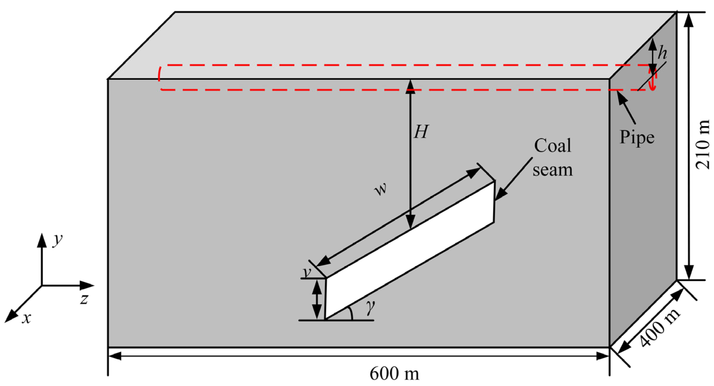
The yield stress of the pipeline is 555 MPa, and the buried depth of the pipeline is 2 m. The goaf soil model size is 400 m × 210 m × 600 m. H represents the mining depth, w represents the width of the mining area, and represents the mining area height. represents the coal-seam dip angle, and h represents the buried depth of the pipeline. The rock strata parameters of the soil and pipe trench backfill soil were obtained from the literature [17,18,19]. The diagram of the goaf gas pipeline is shown in Figure 1, and the specific parameters are presented in Table 1.
2.2. Soil Model of Each Rock Stratum
Generally, rock soil has nonlinear, elastoplastic, and dilatant characteristics [20,21]. Considering continuous coal mining processes, buried pipelines are gradually affected by the mined-out collapse, and the soil properties significantly affect the stress and deformation of buried pipelines. Therefore, soil properties influence the mechanical behavior of buried pipelines. When the internal friction angle of the soil [22] is >22°, the Mohr–Coulomb model [23] in ABAQUS should be used for soil modeling, ensuring the reliability of the simulation results. This model is robust and has adaptability concerning different loads applied to the soil; thus, it has been widely used in engineering and was used for soil modeling in the present study.
2.3. Pipeline Model
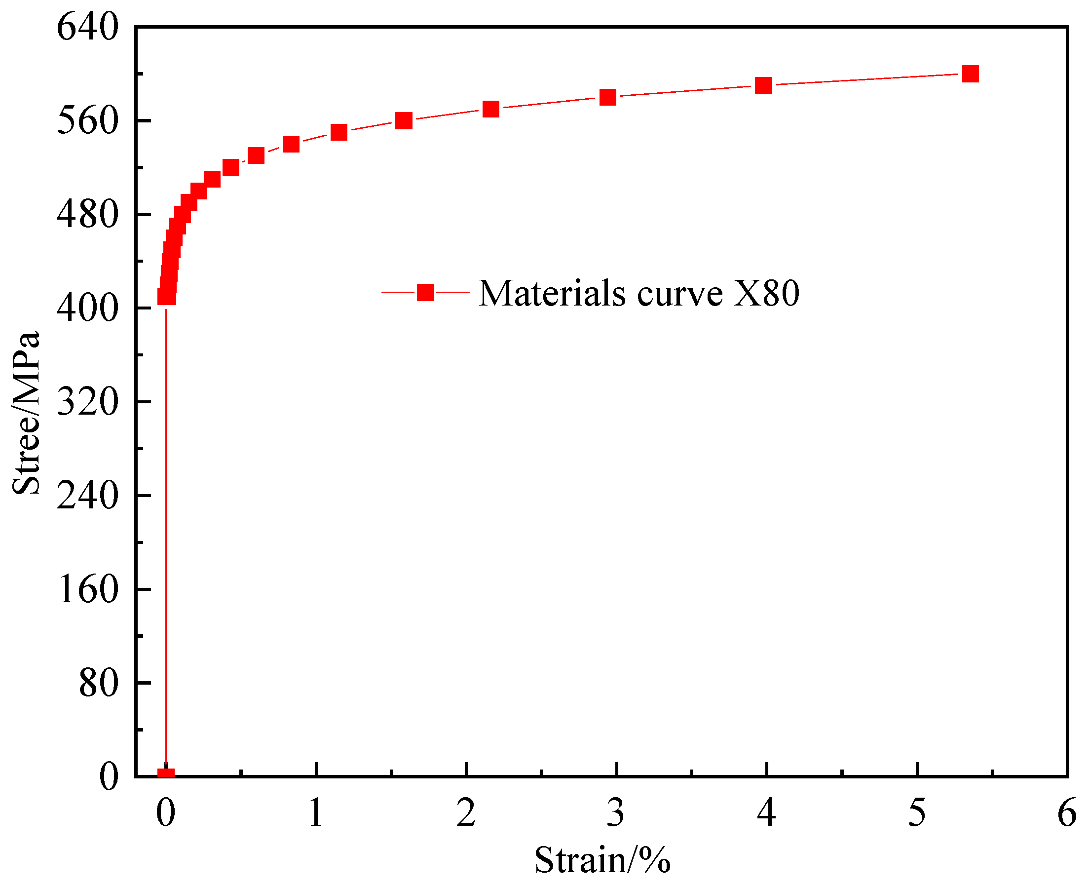
An X80 high-steel-grade pipe is used in the pipeline model, as shown in Figure 2. The Ramberg–Osgood constitutive model [24] is used to describe the true stress–strain relationship of the pipe, which is given as follows:
where represents the real strain, represents the axial stress (in MPa), E represents the elastic modulus (in MPa), represents the yield strength (in MPa), α = 0.4 is the hardening coefficient, and v = 17.15 is the strain hardening index.
2.4. Finite-Element Model of Pipe–Soil Interaction
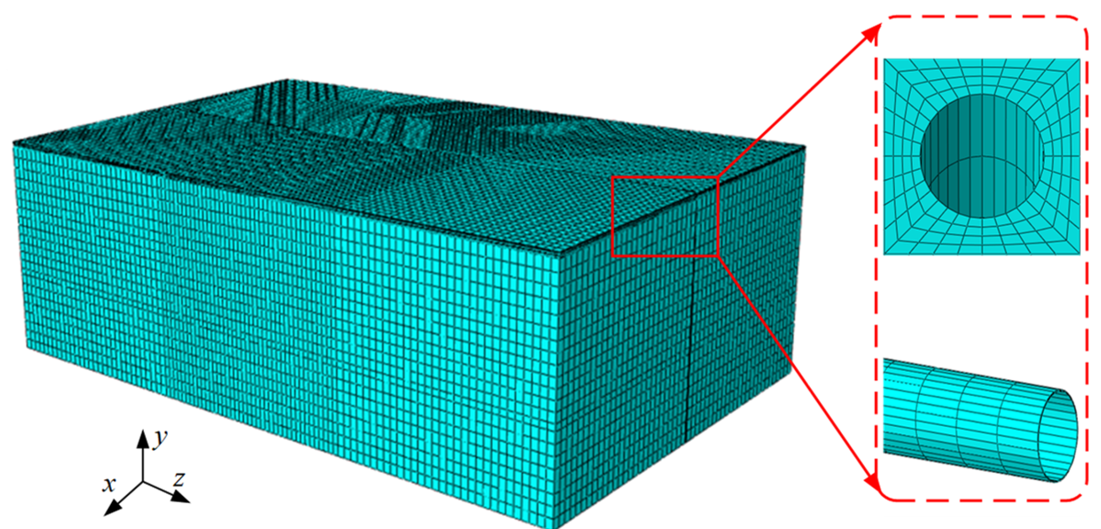
In this study, the finite-element method [25] was used to simulate the influence of a mined-out area that has collapsed on a buried pipeline. The finite-element model is shown in Figure 3. Under this working condition, the buried pipeline has a complex nonlinear relationship with the surrounding soil, which is described by defining the tangential and normal interactions between the buried pipeline and soil in the finite-element model. To ensure that the simulation results conform to the actual working conditions, reasonable boundary conditions are set in the finite-element model for this study. The soil model and the pipe model are constrained symmetrically, and the pipe–soil displacement is constrained in the normal direction. The upper surface of the model is free of constraints. No displacement occurs on the lower surface of the model, and all displacement degrees of freedom are constrained. According to the actual working conditions, an internal pressure of 10 MPa is applied to the inner surface of the model pipe, and a gravitational acceleration of g = –9.8 m/s2 is applied to the overall model in the Y-axis direction.
2.5. Validation of the Finite-Element Model
Because the process of surface subsidence is not monitored in real time in this project, the finite-element model cannot be validated using measurements. In the present study, the following two methods are used for validating the finite-element model and ensuring the accuracy of the results: (1) The sensitivity of the results of the model to the finite-element and mesh size are analyzed. (2) The simulation results of the finite-element model are compared with those of other researchers.
- (1)
- Grid verification
The size of the soil model is set at 400 m × 210 m × 600 m, the internal pressure of the pipeline is set at 10 MPa, and the width of the goaf is set at 100 m. The soil model grid size is set at 5, 10, 15, 20, and 25 m, and the effect of the grid size on the calculation results is analyzed. The maximum von Mises stress and the maximum subsidence of the pipeline under different grid sizes are presented in Table 2.
The grid verification results showed that when the mesh size was 10 m, the maximum settlement of the pipeline reached the extreme point, and when the mesh size was reduced from 10 m to 5 m, the maximum Mises stress increased by 0.0015%, which could be ignored. In order to save calculation, the mesh size was set at 10 m in this paper.
- (2)
- Comparison of the finite-element analysis results with theoretical values
The goaf caving area generated by the ground layer will lead to the subsidence of the surface, and the main section pipeline is the biggest threat to safety under the influence of mining resources. The main methods for predicting gob subsidence [26] include the probability integral method, the Weibull distribution method, the typical curve method, and the negative exponential function method. Among them, the probability integral method has been widely used in predicting mining subsidence in China, and its theory has reached a more mature level after a large number of experts and scholars’ research and development. Based on the mining conditions, the probability integral method [27] can be divided into semi-unlimited mining and limited mining to predict the settlement amount. Based on the mining condition of the coal seam in the actual process, this paper can be judged as limited mining. Limited mining refers to the situation where the size of the working face is limited in length. The formulas for calculating surface subsidence (W0(x)) and horizontal movement (U0(x)) on the goaf strike main section are as follows:
where, the expressions of W(x) and U(x) are, respectively, as follows:
where, represents the distance from any point on the surface to the origin of the coordinate (in m), represents the calculation length of the mined-out area of the coal seam (in m), represents the radius of major influence (in m), represents the distance from the calculated point (in m), represents the coefficient of horizontal movement, represents the maximum surface subsidence above the goaf (in m), represents the seam mining thickness (in m), represents the subsidence coefficient, and represents the dip angle of the coal seam (°).
The calculation formulas of the surface subsidence (), lateral displacement (), and axial displacement () along the goaf pipeline are as follows:
where, represents the angle between the pipeline strike and the mining strike, represents the axial direction angle of the pipe.
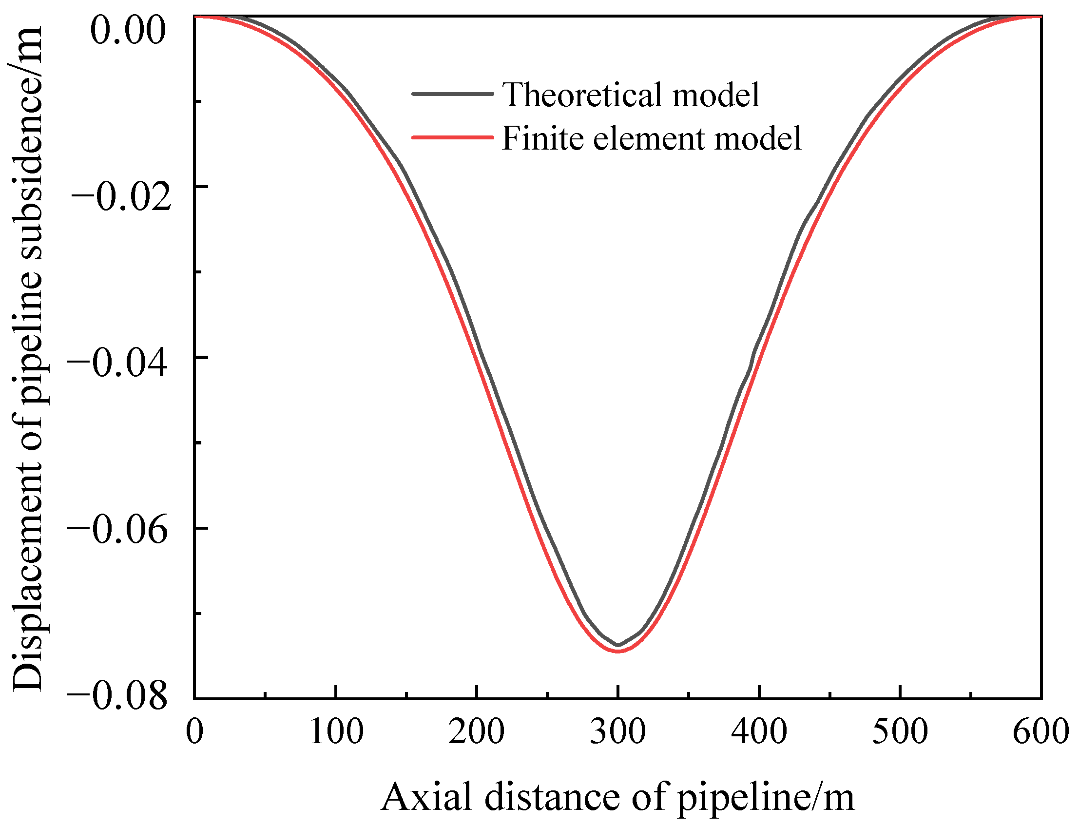
A comparison between the results of the finite-element model and the theoretical model is calculated and is presented in Figure 4, theoretical model results are from literature [28] There are two similarities between the finite-element model and the theoretical model: (1) Both buried pipelines have subsidence in the goaf, and there is no difference between the trend of subsidence and position of maximum stress (both are at an axial distance of 300 m from the pipeline). (2) The maximum subsidence of the pipe in the finite-element model is 0.07448 m, and the maximum subsidence of the pipe in the theoretical model is 0.07373 m, with an error of 1.02%. The error is within the allowable range; thus, the accuracy and feasibility of the developed model can be verified.
3. Influencing Factors on the Mechanical Behavior of a Buried Pipeline in the Goaf
3.1. Effect of the Horizontal Angle
The angle between the mining area and the buried pipeline is not always 0° or 90° in practical mining engineering. Figure 5 shows a schematic of the mining area and pipeline strike during longitudinal mining. The paper defines mining along the positive direction of the x-axis as longitudinal mining, and the mining range is 200 m. In this manuscript, the acute angle between the mining direction and pipeline is denoted as θ, and the mining length of the mining area is denoted as EL.
Figure 6 shows the effect of post-mining pipelines in the mining area under a width of 200 m with θ values of 90°, 82.5°, 75°, 67.5°, and 60° (longitudinal mining condition). Figure 6a shows the stress nephogram of the goaf pipeline. As shown in Figure 6b, during the mining of the underground coal seam, the equivalent stress of the pipeline increased with a reduction in the horizontal included angle θ, and the maximum equivalent stress occurred at the center of the pipeline (axial distance of 300 m). As shown in Figure 6c, the maximum equivalent stress of the pipeline decreases nonlinearly with an increase in the horizontal included angle, and the equivalent stress rate of change increases with the horizontal included angle. Additionally, with an increase in the mining length, the high-stress zone of the pipeline barely changes after the underground coal seam mining is completed; thereafter, the high-stress zone appears along the circumferential direction of the pipeline. When the horizontal angle θ is 90°, the maximum equivalent stress of the pipeline is 374.91 MPa. When the horizontal angle θ is 60°, the maximum equivalent stress of the pipeline is 425.89 MPa, and the pipeline has reached the failure state. Figure 6d shows the maximum von Mises stress of the pipeline for different mining lengths. The maximum equivalent stress of the pipeline increases throughout the mining process. When EL = 400 m, the maximum equivalent stress is 425.89 MPa, and the pipeline equivalent stress reaches its peak. Throughout the mining period, the greater the Angle between pipeline and working face, the faster the change rate of maximum equivalent stress of pipeline. With the increase of mining length, the change rate of maximum equivalent stress of pipeline becomes faster.
As shown in Figure 7a, with an increase in the excavation length, local high-stress zones gradually appear in the middle of the pipeline, directly above the mining area. Considering the mining of the underground coal seam, the high-stress zone gradually expands along the axial direction of the pipeline. When the mining length is <200 m, no high-stress zone appears on the pipeline surface. When the mining length is 200 m, the pipeline exhibits a high-stress zone. Overall, the high-stress zone of the pipeline barely changes; however, the equivalent stress in the center of the pipeline increases continuously. Thereafter, a high-stress zone appears along the circumferential direction of the pipeline. The equivalent stress of the pipeline remains lower than the yield strength throughout the mining process, indicating that the pipeline has only elastic rather than plastic deformation. Figure 7b shows the Y-X plane view of the formation. When the mining length is 40 m, the formation has a small displacement range, which is concentrated above the mining area and has negligible impact on the surface. Surface subsidence occurs, and its range gradually increases during the mining process. The displacement of the mining area is maximized when the mining is completed. The resulting stratum displacement indicates that the upper surface settlement and lower surface uplift of the mining area increase. Therefore, when the subsidence is excessively large, the mining area may collapse.
3.2. Effect of Friction Coefficient
Figure 8 shows the effects of the goaf width and friction coefficient on the von Mises stress of the buried pipeline. Figure 8a–e presents the effects of varying friction coefficients on the von Mises stress of the pipeline for goaf widths of 100, 150, 200, 250, and 300 m, respectively. Figure 8f exhibits the variation in the maximum von Mises stress with respect to the friction coefficient for varying goaf widths.
As shown in Figure 8, the von Mises stress increases gradually with an increase in the friction coefficient at the same mining area width. Additionally, the von Mises stress increases gradually with an increase in the mining area width. The maximum von Mises stress occurs at the center of the pipeline when the friction coefficient is constant. As shown in Figure 8f, when the width of the goaf is 100, 150, 200, 250, and 300 m and the friction coefficient increases from 0.3 to 0.5, the maximum von Mises stress of the pipeline increases by 0.59%, 1.20%, 1.75%, 1.99%, and 2.12%, respectively. The maximum on Mises stress increases gradually under the influence of the friction coefficient with an increasing goaf width.
The results indicate that soft materials can be used to backfill the pipe crossing the goaf when laying it. At this time, the soil particle gap increases and the tangential friction coefficient of the pipe and soil decreases, which can reduce the pipe stress.
3.3. Effect of Coal-Seam Dip Angle
Figure 9 shows the effects of the mined-out area width and coal-seam dip angle on the von Mises stress of the buried pipeline. Figure 9a–e presents the effects of the coal-seam angle on the von Mises stress of the pipeline for goaf widths of 100, 150, 200, 250, and 300 m, respectively. Figure 9f indicates the variation in the maximum von Mises stress of the pipeline with respect to the coal-seam dip angle for varying goaf widths.
As shown in Figure 9, the von Mises stress decreases gradually with an increase in the coal-seam inclination angle for the same mining-area width. The von Mises stress increases gradually with an increase in the mining-area width for the same coal-seam dip angle, and the maximum stress is 442 MPa. With an increase in the coal-seam dip angle, the position of the maximum stress towards the uphill side of the coal seam. The maximum equivalent stress of the pipeline is 432 MPa when the inclination angle of the coal seam is 15° and the goaf width is 300 m; the pipeline fails under these working conditions. According to the foregoing analysis, the mining angle of the coal seam can be adjusted appropriately, reducing the impact of mining the coal seam on the gas transmission pipeline above the goaf. Therefore, it is recommended to mine the coal seam using a 15° dip angle in practical engineering.
4. Conclusions
The effects of different parameters on the pipeline stress were analyzed by developing a three-dimensional finite-element model of the pipe–soil interaction regarding buried pipelines passing through a goaf. The following conclusions are drawn:
- (1)
- The equivalent stress of the pipeline increases when the horizontal angle of inclination is reduced, whereas the maximum equivalent stress occurs at the center of the pipeline. With a reduction in the horizontal angle, the high-stress zone of the pipeline barely changes after the coal-seam mining is complete; however, the maximum equivalent stress increases. In the process of coal-seam mining, a lesser angle between the pipeline and the coal-seam mining strike corresponds to a faster increase in the maximum equivalent stress of the pipeline; the change in the equivalent stress of the pipeline increases with the mining length.
- (2)
- A local high-stress zone gradually appears with an increase in the excavation length when the coal seam is mined longitudinally. The high-stress zone of the pipeline remains stable when the mining length is >200 m. When the mining length is 40 m, a small amount of stratum displacement occurs in a small range, which is mainly concentrated above the mining area and has no surface impact. Surface displacement gradually occurs, and the range of the stratum displacement gradually increases with an increasing mining length.
- (3)
- The equivalent stress of the pipeline increases with an increase in the pipe–soil friction coefficient when the width of the goaf is constant. The effect of the pipe–soil friction coefficient on the equivalent stress of the pipeline is significantly apparent with a wider goaf.
- (4)
- With an increase in the coal-seam dip angle, the von Mises stress decreases, and the position of the maximum stress towards the side of the coal-seam uphill. The maximum equivalent stress of the pipeline is 432 MPa when the inclination angle of the coal seam is 15° and the goaf width is 300 m. The pipeline reached failure under these working conditions. Therefore, to reduce the influence of coal mining on the gas pipeline above the goaf, the mining angle of the coal seam should be maximized.
- (5)
- We suggest that the angle between the coal seam mining direction and the pipeline axial direction be 90° to reduce the influence of coal seam mining on the buried pipeline when it is horizontal. For the coal seam with a dip angle to the horizontal direction, we suggest that the mining direction and the horizontal direction be inclined to mining in order to reduce the influence of coal seam mining on the buried pipe.
- (6)
- The pipeline is affected not only by internal pressure but also by internal fluid. We suggest to introduce the fluid-structure coupling model to study the mechanical behavior of the goaf pipeline in practical engineering.
Author Contributions
Conceptualization, B.Z.; Methodology, B.Z., H.Z. and Y.Z.; Software, B.Z., H.Z., Y.W., Y.Z. and J.Z.; Validation, H.Z., Y.Z. and J.Z.; Formal analysis, Y.W.; Investigation, B.Z., H.Z., Y.W., Y.Z. and J.Z.; Resources, Y.W.; Data curation, B.Z., H.Z., Y.W. and J.Z.; Writing—original draft, B.Z. and H.Z.; Writing—review & editing, Y.W.; Visualization, H.Z., Y.Z. and J.Z.; Supervision, B.Z.; Project administration, B.Z. and Y.W.; Funding acquisition, B.Z. All authors have read and agreed to the published version of the manuscript.
Funding
This research received no external funding.
Data Availability Statement
Data sharing not applicable.
Conflicts of Interest
The authors declare no conflict of interest.
References
- Wang, T.; Wei, S.; Jiang, B.; Li, L. Effect of surface deformation of steeply inclined goaf on pipeline. Acta Geol. Sin. 2019, 93, 314–318. [Google Scholar]
- Xia, M.; Zhang, H.; Wang, B.; Gu, X. Strain analysis of buried pipelines in continuous mining subsidence areas based on shell element. Oil Gas Storage Transp. 2018, 37, 256–262. [Google Scholar]
- Karmis, M. Mining subsidence and its prediction in the Appalachian coalfield. Int. J. Rock Mech. Min. Sci. Geomech. Abstr. 1984, 21, 64. [Google Scholar]
- Peng, S.S.; Lou, Y. Determination of stress field in buried thin pipelines resulting from ground subsidence due to longwall mining. Min. Sci. Technol. 1988, 6, 205–216. [Google Scholar] [CrossRef]
- Xu, X.D.; He, K.; Su, Y. Safety analysis of pipe-soil coordination deformation affected by mining subsidence. Geotech. Geol. Eng. 2020, 38, 2187–2198. [Google Scholar] [CrossRef]
- Cao, Y.; Zhen, Y.; He, Y.; Zhang, S.; Sun, Y.; Yi, H.; Liu, F. Prediction of limit pressure in axial through-wall cracked X80 pipeline based on critical crack-tip opening angle. J. China Univ. Pet. 2017, 41, 139–146. [Google Scholar]
- Zhen, Y.; Tian, H.; Yi, H.; Cao, Y.; Zhang, S. Constraint-corrected fracture failure criterion based on CTOD/CTOA. Int. J. Fract. 2018, 214, 115–127. [Google Scholar] [CrossRef]
- Liu, X.; Zhang, H.; Han, Y.; Xia, M.; Zheng, W. A semi-empirical model for peak strain prediction of buried X80 steel pipelines under compression and bending at strike-slip fault crossings. J. Nat. Gas Sci. Eng. 2016, 32, 465–475. [Google Scholar] [CrossRef]
- Han, B.; Wang, Z.; Wu, Z.; Zhao, H.; Jing, H. Application of strain-based theory in failure analysis of pipeline subjected to mining collapse areas. J. China Univ. Pet. 2012, 36, 6. [Google Scholar]
- Iwanec, A.M.S.; Carter, J.P.; Hambleton, J.P. Geomechanics of subsidence above single and multi-seam coal mining. J. Rock Mech. Geotech. Eng. 2016, 8, 304–313. [Google Scholar] [CrossRef] [Green Version]
- Wang, Z.; Song, G.; Ding, K.; Bellucci, S. Study on the Ground Movement in an Open-Pit Mine in the Case of Combined Surface and Underground Mining. Adv. Mater. Sci. Eng. 2020, 2020, 8728653. [Google Scholar] [CrossRef]
- Kalisz, P. Impact of Mining Subsidence on Natural Gas Pipeline Failures. IOP Conf. Ser. Mater. Sci. Eng. 2019, 471, 042024. [Google Scholar] [CrossRef]
- Wang, X.; Shuai, J.; Zhang, J. Mechanical response analysis of buried pipeline crossing mining subsidence area. Rock Soil Mech. 2011, 32, 3373–3378. [Google Scholar]
- Wang, H.; Zhao, X. Stress Deformation Analysis of Buried Pipeline under Mining Subsidence. Pipeline Tech. Equip. 2019, 6, 6. [Google Scholar] [CrossRef]
- Wang, X.; Zhou, X.; Li, S.; Zhang, N.; Ji, L.; Lu, H. Mechanism Study of Hydrocarbon Differential Distribution Controlled by the Activity of Growing Faults in Faulted Basins: Case Study of Paleogene in the Wang Guantun Area, Bohai Bay Basin, China. Lithosphere 2022, 2021, 7115985. [Google Scholar] [CrossRef]
- Zhang, J.; Liang, Z.; Han, C. Mechanical behaviour analysis of buried pressure pipeline crossing ground settlement zone. Int. J. Pavement Eng. 2015, 18, 608–621. [Google Scholar] [CrossRef]
- Zhang, P.; Hu, B.; Li, H.; Chen, X. Influence of different crossing angles on mechanical behavior of buried pipeline in goaf. J. Saf. Sci. Technol. 2020, 16, 82–88. [Google Scholar]
- Wu, K.; Zhang, H.; Liu, X.; Liu, J.; Fang, M.; Wang, B.; Zheng, W. Analysis on rationality of trench geometrical size for buried X80 natural gas pipeline under strike—Slip fault displacement. J. Saf. Sci. Technol. 2017, 13, 81–85. [Google Scholar]
- Cheng, X.; Huang, R.; Xu, L.; Ma, C.; Zhu, X. Parametric study on the trench designing for X80 buried steel pipeline crossing oblique-reverse fault. Soil Dyn. Earthq. Eng. 2021, 150, 106824. [Google Scholar] [CrossRef]
- Wang, X.; Hou, J.; Li, S.; Dou, L.; Song, S.; Kang, Q.; Wang, D. Insight into the nanoscale pore structure of organic-rich shales in the Bakken Formation, USA. J. Pet. Sci. Eng. 2019, 176, 312–320. [Google Scholar] [CrossRef]
- Wang, X.; Liu, Y.; Hou, J.; Li, S.; Kang, Q.; Sun, S.; Ji, L.; Sun, J.; Ma, R. The relationship between synsedimentary fault activity and reservoir quality—A case study of the Ek1 formation in the Wang Guantun area, China. Interpretation 2020, 8, sm15–sm24. [Google Scholar] [CrossRef]
- Kang, F.; Jie, P. Detailed Explanation of ABAQUS Geotechnical Engineering Examples; Posts & Telecom Press: Beijing, China, 2017. [Google Scholar]
- Liu, X.; Zhang, H.; Ndubuaku, O.; Xia, M.; Roger Cheng, J.J.; Li, Y.; Adeeb, S. Effects of stress–strain characteristics on local buckling of X80 pipe subjected to strike-slip fault movement. J. Press. Vessel. Technol. 2018, 140, 041408. [Google Scholar] [CrossRef]
- Yu, C.; Han, C.; Xie, R.; Wang, L. Mechanical behavior analysis of buried pipeline under stratum settlement caused by underground mining. Int. J. Press. Vessel. Pip. 2020, 188, 104212. [Google Scholar] [CrossRef]
- Zhang, J.; Liang, Z.; Han, C.J. Buckling behavior analysis of buried gas pipeline under strike-slip fault displacement. J. Nat. Gas Sci. Eng. 2014, 21, 921–928. [Google Scholar] [CrossRef]
- Wang, X. Research on Safety Assessment of Buried Pipeline in Typically Poor Geological Conditions. Diploma Thesis, China University of Petroleum (Beijing), Beijing, China, 2009; pp. 10–43. [Google Scholar]
- He, G. Mining Subsidence; China University of Mining and Technology Press: Xuzhou, China, 1991; pp. 116–148. [Google Scholar]
- Zhao, X. Stress and Deformation Analysis and Remote Monitoring of Buried Pipeline in Mined-Out Subsidence Area. Master’s Thesis, Southwest Petroleum University, Chengdu, China, 2015. [Google Scholar]
Figure 1.
Geometric model of natural gas pipeline through goaf.

Figure 2.
True stress–strain curve of the X80 steel.

Figure 3.
Finite-element model meshing.

Figure 4.
Comparison for model validation.

Figure 5.
Schematic of the mining area and pipeline strike under the longitudinal mining condition.

Figure 6.
Equivalent stress distributions of the pipeline at different horizontal included angles. (a) Stress nephogram of the goaf pipeline. (b) Curve of the equivalent stress change of the pipeline after mining. (c) Curve of the maximum equivalent stress of the pipeline. (d) Maximum equivalent stress of the pipeline for different mining lengths.


Figure 7.
Pipeline and formation cloud maps for different mining lengths. (a) Cloud maps of the pipeline stress for different mining lengths. (b) Displacement cloud maps of the strata for different mining lengths.
Figure 7.
Pipeline and formation cloud maps for different mining lengths. (a) Cloud maps of the pipeline stress for different mining lengths. (b) Displacement cloud maps of the strata for different mining lengths.

Figure 8.
Von Mises stress curves of the pipe with different tangential friction coefficients. (a) Goaf width of 100 m. (b) Goaf width of 150 m. (c) Goaf width of 200 m. (d) Goaf width of 250 m. (e) Goaf width of 300 m. (f) Maximum von Mises stress of the pipe.
Figure 8.
Von Mises stress curves of the pipe with different tangential friction coefficients. (a) Goaf width of 100 m. (b) Goaf width of 150 m. (c) Goaf width of 200 m. (d) Goaf width of 250 m. (e) Goaf width of 300 m. (f) Maximum von Mises stress of the pipe.


Figure 9.
Von Mises stress curves of the pipe for different coal-seam dip angles. (a) Goaf width of 100 m. (b) Goaf width of 150 m. (c) Goaf width of 200 m. (d) Goaf width of 250 m. (e) Goaf width of 300 m. (f) Maximum von Mises stress of the pipe.
Figure 9.
Von Mises stress curves of the pipe for different coal-seam dip angles. (a) Goaf width of 100 m. (b) Goaf width of 150 m. (c) Goaf width of 200 m. (d) Goaf width of 250 m. (e) Goaf width of 300 m. (f) Maximum von Mises stress of the pipe.


Table 1.
Physical parameters of the pipeline and rock strata.
| Rock Classification | Density/kg·m−3 | Elastic Modulus/MPa | Poisson’s Ratio | Cohesion/MPa | Friction Angle/° | Expansion Angle/° |
|---|---|---|---|---|---|---|
| Overlying soil | 1960 | 110 | 0.3 | 5.0 | 30 | 15 |
| Argillaceous siltstone | 2500 | 3800 | 0.25 | 2.994 | 40 | 15 |
| Silty Mudstone | 2474 | 1400 | 0.25 | 2.766 | 38 | 15 |
| Coal seam | 1500 | 2000 | 0.25 | 1.0 | 30 | 15 |
| Sandstone | 2548 | 26,000 | 0.25 | 4.306 | 39.4 | 15 |
| Backfill soil | 1560 | 24.7 | 0.3 | 0 | 40 | 10 |
| Pipeline | 7833 | 210,000 | 0.3 |
Table 2.
Mesh sensitivity analysis results.
| Grid Size/m | Grid Number | Maximum Subsidence/m | Maximum von Mises Stress/MPa |
|---|---|---|---|
| 5 | 578,884 | –0.07438 | 265.68 |
| 10 | 233,522 | –0.07448 | 265.64 |
| 15 | 75,642 | –0.07006 | 265.23 |
| 20 | 43,976 | –0.06733 | 264.92 |
| 25 | 27,364 | –0.06243 | 263.72 |
Disclaimer/Publisher’s Note: The statements, opinions and data contained in all publications are solely those of the individual author(s) and contributor(s) and not of MDPI and/or the editor(s). MDPI and/or the editor(s) disclaim responsibility for any injury to people or property resulting from any ideas, methods, instructions or products referred to in the content. |
© 2023 by the authors. Licensee MDPI, Basel, Switzerland. This article is an open access article distributed under the terms and conditions of the Creative Commons Attribution (CC BY) license (https://creativecommons.org/licenses/by/4.0/).
Share and Cite
MDPI and ACS Style
Zhao, B.; Zhang, H.; Wang, Y.; Zhou, Y.; Zhang, J. Mechanical Behavior of Gas-Transmission Pipeline in a Goaf. Processes 2023, 11, 1022. https://doi.org/10.3390/pr11041022
AMA Style
Zhao B, Zhang H, Wang Y, Zhou Y, Zhang J. Mechanical Behavior of Gas-Transmission Pipeline in a Goaf. Processes. 2023; 11(4):1022. https://doi.org/10.3390/pr11041022
Chicago/Turabian StyleZhao, Bin, Hailun Zhang, Yu Wang, Yutong Zhou, and Jiaxin Zhang. 2023. "Mechanical Behavior of Gas-Transmission Pipeline in a Goaf" Processes 11, no. 4: 1022. https://doi.org/10.3390/pr11041022
Note that from the first issue of 2016, this journal uses article numbers instead of page numbers. See further details here.