
Numerical Simulation and Process Enhancement of the Hydrolysis of 2-Chlorobenzal Chloride
 ,
,
Abstract
:1. Introduction
2. Material and Methods
2.1. Experimental Materials
2.2. Instruments and Equipment
2.3. Methods
2.3.1. Geometric Model and Grid Partition
2.3.2. Physical Model and Governing Equation
2.3.3. Model Solving
2.3.4. Selection of Reaction Vessel Simulation Conditions
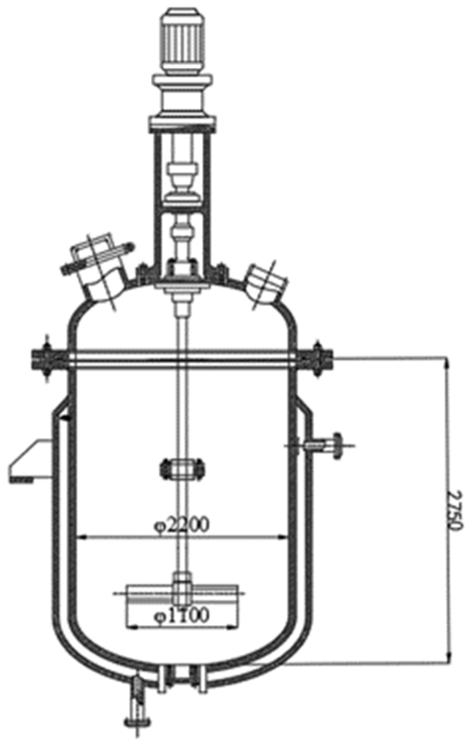
2.3.5. Design and Production of the 2-Chlorobenzal Chloride Hydrolysis Reaction Kettle
2.3.6. 2-Chlorobenzal Chloride Hydrolysis Reaction Conditions
2.3.7. Optimization of the 2-Chlorobenzal Chloride Hydrolysis Process
2.3.8. Measurement of the Conversion Rate of 2-Chlorobenzal Chloride
3. Results and Discussion
3.1. Numerical Simulation and Optimization of Stirring Conditions for the Hydrolysis Reaction of the Lab-Scale Tests
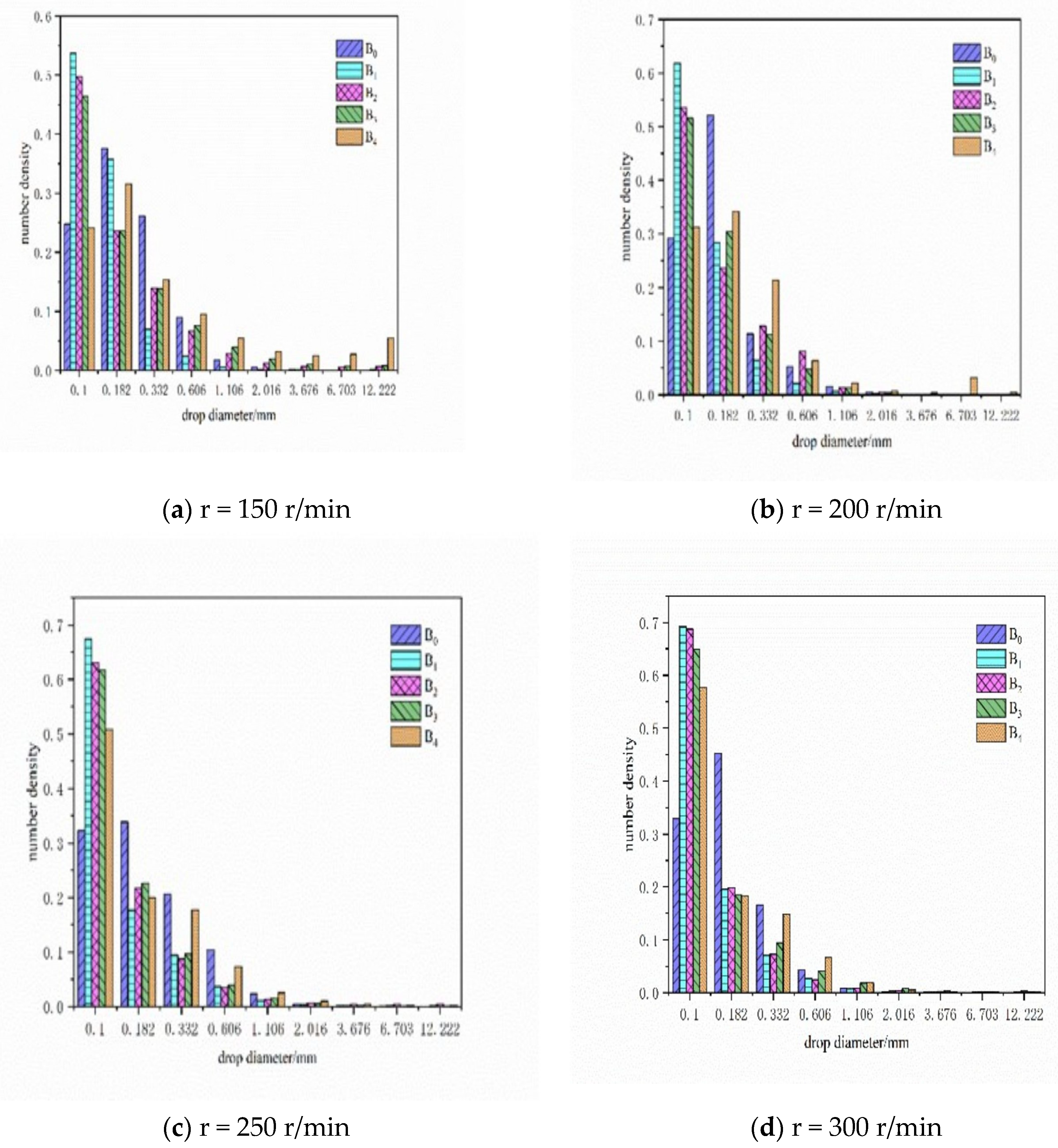
3.1.1. Particle Size Distribution of Dispersed Phase Droplets in Different Stirring Systems
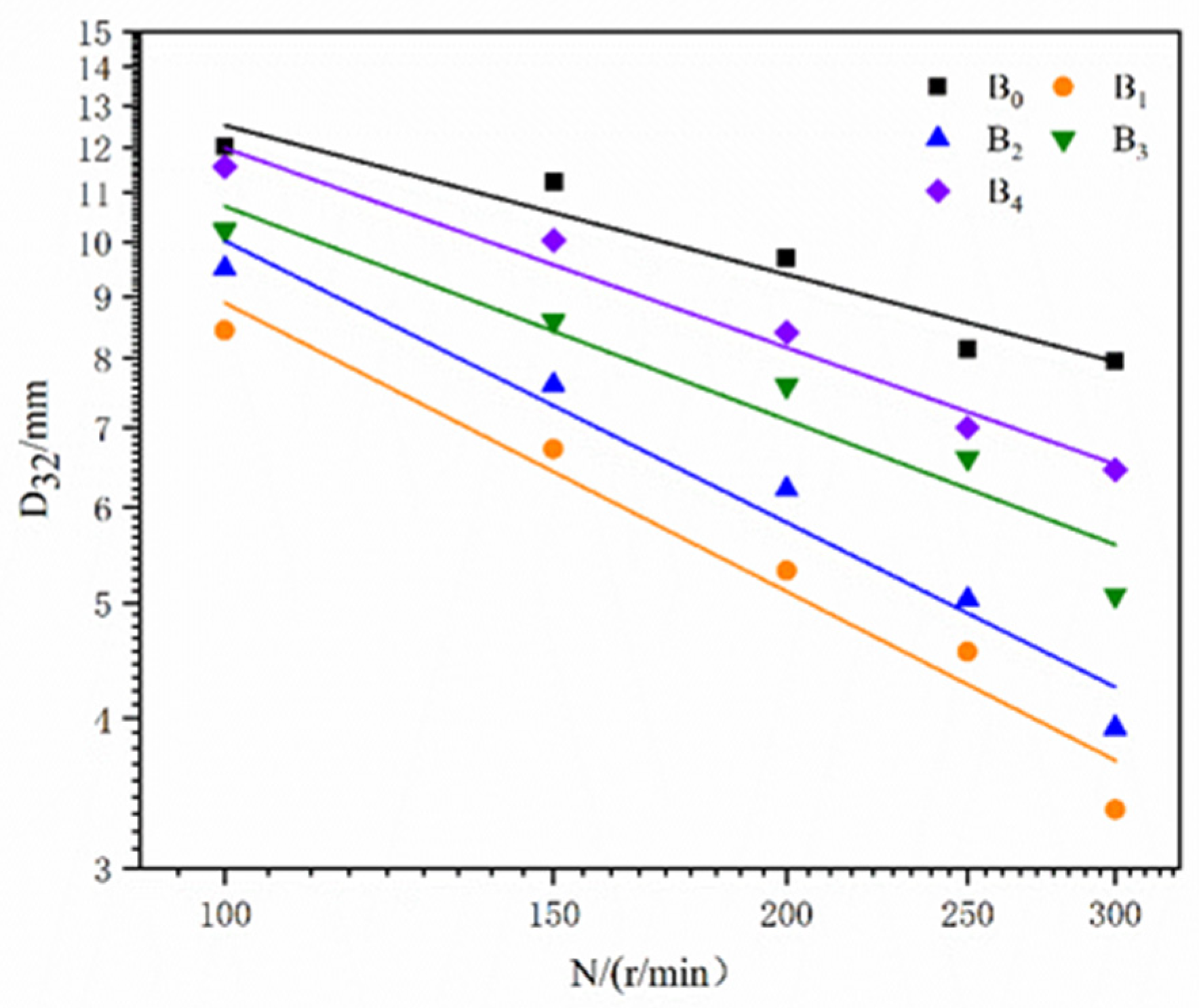
3.1.2. Comparison of D32 for Different Stirring Systems at Different Speeds
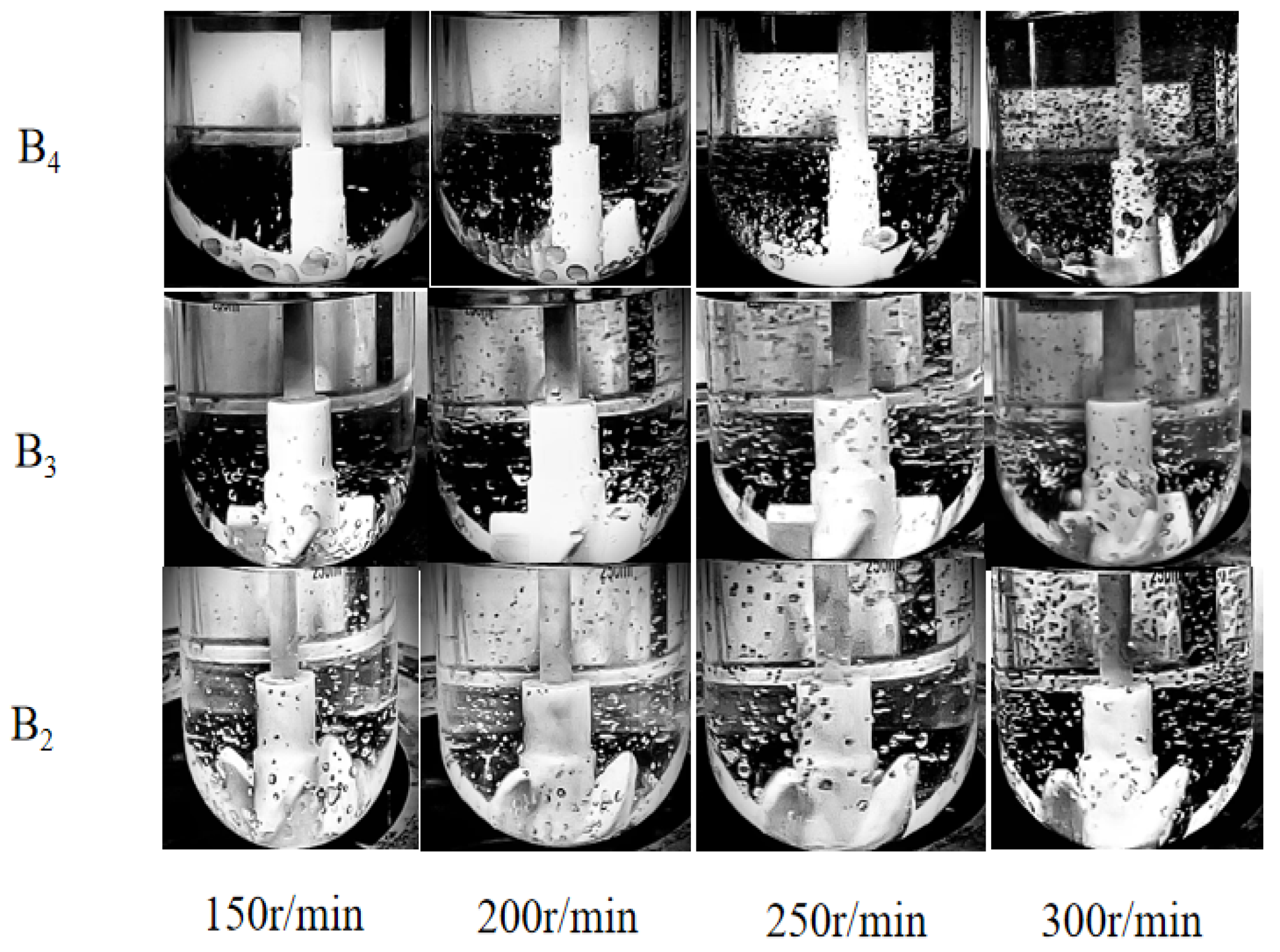
3.2. Experimental Measurement of the Diameter of Dispersed Phase Droplets
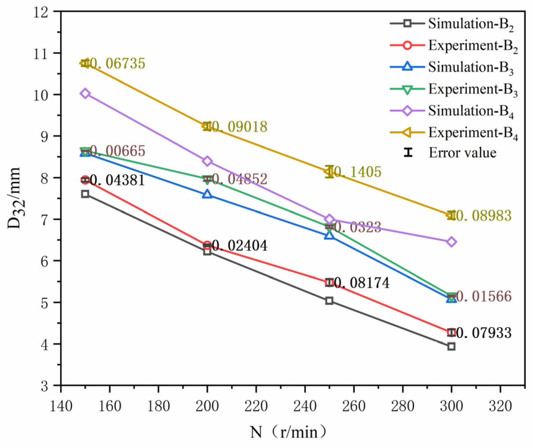
3.3. Lab-Scale Validation of Numerical Simulation Results
3.3.1. Effect of Stirring Paddle Type on the Conversion Rate of 2-Chlorobenzal Chloride
3.3.2. Effect of Stirring Rate on the Conversion Rate of 2-Chlorobenzal Chloride
3.3.3. Effect of Hydrolysis Reaction Time on the Selectivity of 2-Chlorobenzaldehyde
3.4. Lab-Scale Validation and Optimization of Intensification Conditions of the Hydrolysis Reaction
3.5. Industrial-Scale Application of the Optimization Results of Hydrolysis Reaction Conditions in Lab-Scale Tests
4. Conclusions
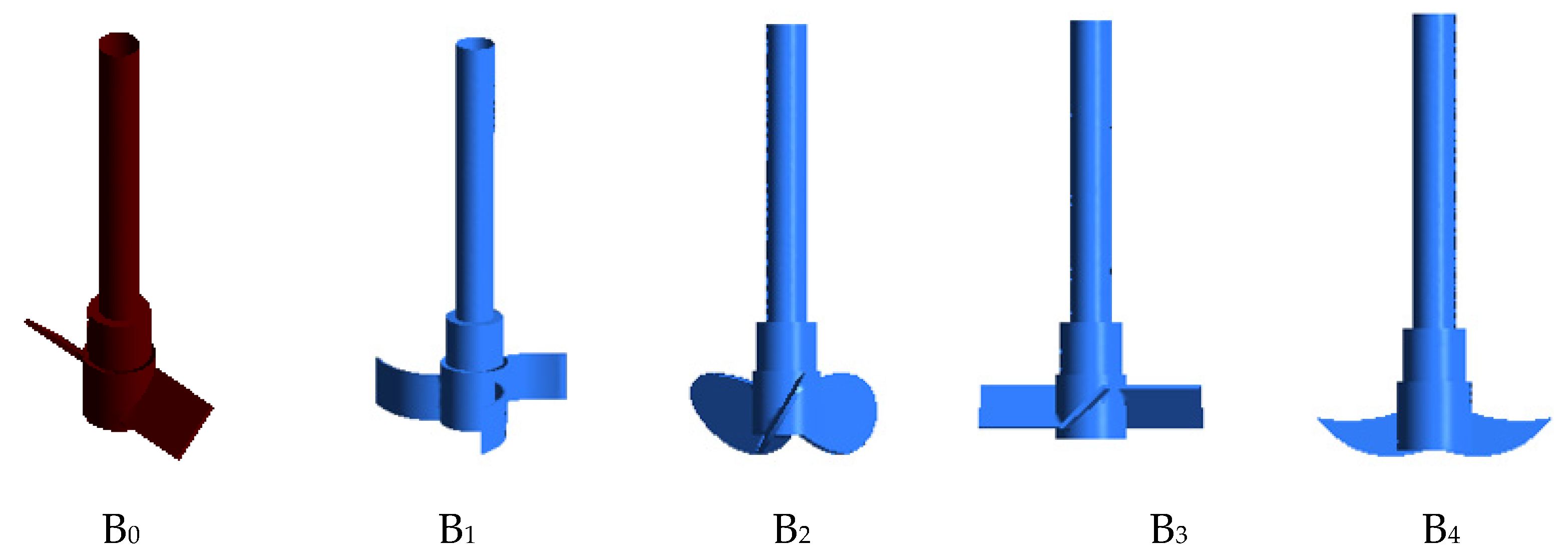
- The dispersion characteristics of droplets in the reactor are simulated and analyzed by using Fluent software, and the dichotomous leaf hydrolysis agitator commonly used in hydrolysis kettles in industrial production is strengthened. The simulation results are also verified by the Sauter mean diameter (D32) measurement experiment of dispersed phase droplets and hydrolysis experiments. The results show that the simulated and experimental results are in good agreement. A log-linear relationship exists between the Sauter mean diameter (D32) of the dispersed phase in different stirred systems and the rotational speed. The three-blade back-curved stirring system possesses a more significant number of tiny droplets and a more uniform particle size, which can enhance the stirrer and mass transfer in the hydrolysis reaction system.
- A lab-scale hydrolysis reactor is designed and produced based on the scheme of the industrial hydrolysis kettle equipped with a three-bladed back-curved stirring paddle. Under the same conditions, the effect of the hydrolysis reaction is verified, and the process conditions are strengthened. The results show that, compared with the case in the reactor using a dichotomous leaf hydrolysis agitator at the same reaction temperature and catalyst conditions, the reaction time of hydrolysis completion reduced to 58.33% at the lab-scale at the stirring rate of 446 r/min using a three-bladed back-curved stirring paddle. In addition, the reaction time can be reduced to 63.89% of the pre-intensification level by applying the optimized lab-scale technique to industrial-scale production.
Author Contributions
Funding
Data Availability Statement
Acknowledgments
Conflicts of Interest
References
- Wu, W.; Shi, S.J.; Chen, W.J. Preparation of o-chlorobenzaldehyde by hydrolysis of o-chlorobenzalchloride. Sci. Technol. Inf. 2013, 34, 4–6. [Google Scholar]
- Nikolić, D.D.; Frawley, P.J. Application of the Lagrangian meshfree approach to modelling of batch crystallisation: Part I—Modelling of stirred tank hydrodynamics. Chem. Eng. Sci. 2016, 145, 317–328. [Google Scholar] [CrossRef] [Green Version]
- Ayranci, I.; Kresta, S.M. Design rules for suspending concentrated mixtures of solids in stirred tanks. Chem. Eng. Res. Des. 2011, 89, 1961–1971. [Google Scholar] [CrossRef]
- Sardeshpande, M.V.; Kumar, G.; Aditya, T.; Ranade, V.V. Mixing studies in unbaffled stirred tank reactor using electrical resistance tomography. Flow Meas. Instrum. 2016, 47, 110–121. [Google Scholar] [CrossRef]
- Montante, G.; Paglianti, A. Gas hold-up distribution and mixing time in gas–liquid stirred tanks. Chem. Eng. J. 2015, 279, 648–658. [Google Scholar] [CrossRef]
- Solsvik, J.; Jakobsen, H.A. Single drop breakup experiments in stirred liquid–liquid tank. Eng. Sci. 2015, 131, 219–234. [Google Scholar] [CrossRef]
- Li, W.L. Study on the relationship between the height of liquid level drop and the shape of the structure of reactor’s bottom in multiphase stirred reactor by using CFD. Fine Spec. Chem. 2022, 30, 53–58. [Google Scholar]
- Su, Y.; Yu, P.Q.; Huang, Z.J. Applications of mixing technique in polymerization reaction kettle. Chem. Propellants Polym. Mater. 2003, 1, 19–23. [Google Scholar]
- Svensson, F.J.; Rasmuson, A. PIV measurements in a liquid–liquid system at volume percentages up to 10% dispersed phase. Exp. Fluids 2006, 41, 917–931. [Google Scholar] [CrossRef]
- Drumm, C.; Tiwari, S.; Kuhnert, J.; Bart, H.J. Finite pointset method for simulation of the liquid–liquid flow field in an extractor. Comput. Chem. Eng. 2008, 32, 2946–2957. [Google Scholar] [CrossRef]
- Lamberto, D.J.; Muzzio, F.J.; Swanson, P.D.; Tonkovich, A.L. Using time-dependent RPM to enhance mixing in stirred vessels. Chem. Eng. Sci. 1996, 51, 733–741. [Google Scholar] [CrossRef]
- Lamberto, D.J.; Alvarez, M.M.; Muzzio, F.J. Computational analysis of regular and chaotic mixing in a stirred tank reactor. Chem. Eng. Sci. 2001, 56, 4887–4899. [Google Scholar] [CrossRef]
- Eastwood, C.D.; Armi, L.; Lasheras, J.C. The breakup of immiscible fluids in turbulent flows. J. Fluid Mech. 2004, 502, 309–333. [Google Scholar] [CrossRef] [Green Version]
- Li, X. Design and fatigue study of jacketed reactor. J. Chifeng Univ. Nat. Sci. Ed. 2015, 22, 198–200. [Google Scholar]
- Lu, P.; Li, W.; Zhen, X.W. Numerical simulation on the characteristics of the flow field in glass-lined agitating reactor. Chem. React. Eng. Technol. 2016, 32, 97–105. [Google Scholar]
- Songc, G.; Liy, X.; Wang, W.; Zheng, S. Numerical simulation of hydrate particle size distribution characteristics in pipeline flowing systems. Chem. Ind. Eng. Prog. 2018, 37, 2912–2918. [Google Scholar]
- Lew, A.J.; Buscaglia, G.C.; Carrica, P.M. A note on the numerical treatment of the k-epsilon turbulence model. Int. J. Comput. Fluid D 2001, 14, 201–209. [Google Scholar] [CrossRef]
- Yan, Y.F.; Wang, R.J.; Yang, X.X. CFD simulation of immiscible liquid-liquid dispersion in a stirred tank. Chem. Ind. Eng. 2018, 35, 70–79. [Google Scholar]
- Zhang, H.H.; Wang, T.F. Generality of CFD-PBM coupled model for simulations of gas-liquid bubble column. CIESC J. 2019, 70, 487–495. [Google Scholar]
- Harvey, P.S.; Greaves, M. Turbulent flow in an agitated vessel. Part I: A predictive model. Trans. Inst. Chem. Eng. 1982, 60, 195–200. [Google Scholar]
- Harvey, P.S.; Greaves, M. Turbulent flow in an agitated vessel. Part II: Numerical solution and model predictions. Trans. Inst. Chem. Eng. 1982, 60, 201–210. [Google Scholar]
- Mattei, G.; Vozzi, G. CFD modelling of a mixing chamber for the realization of functionally graded scaffolds. Comput. Chem. Eng. 2016, 84, 43–48. [Google Scholar] [CrossRef] [Green Version]
- Daglas, D.; Stamatoudis, M. Effect of impeller vertical position on drop sizes in agitated dispersions. Chem. Eng. Technol. 2000, 23, 437–440. [Google Scholar] [CrossRef]
- Sechremeli, D.; Stampouli, A.; Stamatoudis, M. Comparison of mean drop size and drop size distributions in agitated liquid-liquid dispersions produced by disk and open type impellers. Chem. Eng. J. 2006, 117, 11. [Google Scholar] [CrossRef]


| Material | Density/(kg/m3) | Viscosity/(kg/m·s) |
|---|---|---|
| water | 998.2 | 1.003 × 10⁻³ |
| 2-chlorobenzal chloride | 1281.32 | 7.356 × 10⁻⁴ |
| Factors | Level | ||
|---|---|---|---|
| −1 | 0 | 1 | |
| A. Reaction time/h | 15 | 20 | 25 |
| B. Stirring rate/(r/min) | 150 | 300 | 450 |
| Type of Carrier Gas | Value of Pressure/(MPa) | Type of Temperature | Value of Temperature/(°C) |
|---|---|---|---|
| N2 | 0.4 | Column | 100 |
| H2 | 0.2 | Detection room | 280 |
| Vaporization room | 280 |
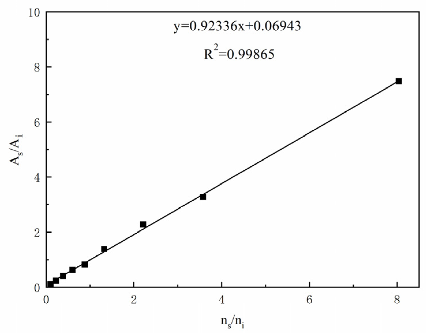
| 8.04 | 7.4806 | 1.075 | 0.9884 |
| 3.575 | 3.2791 | 1.09 | |
| 2.213 | 2.2774 | 0.972 | |
| 1.325 | 1.39075 | 0.9527 | |
| 0.88 | 0.82859 | 1.0620 | |
| 0.6 | 0.62833 | 0.9549 | |
| 0.3857 | 0.40447 | 0.9536 | |
| 0.225 | 0.23823 | 0.9445 | |
| 0.09889 | 0.11079 | 0.8909 |
| Test Number | A Reaction Time | B Stirring Rate | Conversion Rate/% |
|---|---|---|---|
| 1 | −1 | −1 | 77.21 |
| 2 | −1 | 0 | 84.21 |
| 3 | −1 | 1 | 92.14 |
| 4 | 0 | −1 | 91.21 |
| 5 | 0 | 0 | 93.54 |
| 6 | 0 | 1 | 99.97 |
| 7 | 1 | −1 | 98.60 |
| 8 | 1 | 0 | 99.82 |
| 9 | 1 | 1 | 99.92 |
| 10 | 0 | 0 | 94.25 |
| 11 | 0 | 0 | 95.24 |
| 12 | 0 | 0 | 95.09 |
| 13 | 0 | 0 | 96.34 |
| Variance Source | Degree of Freedom | Sum of Squares | Mean Square | F-Value | p-Value | Salience |
|---|---|---|---|---|---|---|
| model | 5 | 516.29 | 103.26 | 134.73 | <0.0001 | ** |
| A Reaction time | 1 | 334.21 | 334.21 | 436.06 | <0.0001 | ** |
| B Stirring rate | 1 | 104.25 | 104.25 | 136.02 | <0.0001 | ** |
| AB | 1 | 46.31 | 46.31 | 60.42 | 0.0001 | ** |
| A2 | 1 | 28.94 | 28.94 | 37.76 | 0.0005 | ** |
| B2 | 1 | 0.32 | 0.32 | 0.41 | 0.5414 | |
| Residuals | 7 | 5.36 | 0.77 | |||
| Misfit | 3 | 0.87 | 0.29 | 0.26 | 0.8531 | ns |
| Pure terror | 4 | 4.5 | 1.12 | |||
| sum | 12 | 521.66 |
| NO. | Reaction Time/h | Conversion Rate/% | Selectivity/% |
|---|---|---|---|
| 1 | 23 | 99.986 | 99.901 |
| 2 | 23 | 99.975 | 99.945 |
| 3 | 23 | 99.972 | 99.932 |
Disclaimer/Publisher’s Note: The statements, opinions and data contained in all publications are solely those of the individual author(s) and contributor(s) and not of MDPI and/or the editor(s). MDPI and/or the editor(s) disclaim responsibility for any injury to people or property resulting from any ideas, methods, instructions or products referred to in the content. |
© 2023 by the authors. Licensee MDPI, Basel, Switzerland. This article is an open access article distributed under the terms and conditions of the Creative Commons Attribution (CC BY) license (https://creativecommons.org/licenses/by/4.0/).
Share and Cite
Li, F.; Dong, L.; Yan, S.; Zhang, Y.; Liu, J.; Tao, W.; Nian, L.; Fu, S. Numerical Simulation and Process Enhancement of the Hydrolysis of 2-Chlorobenzal Chloride. Processes 2023, 11, 945. https://doi.org/10.3390/pr11030945
Li F, Dong L, Yan S, Zhang Y, Liu J, Tao W, Nian L, Fu S. Numerical Simulation and Process Enhancement of the Hydrolysis of 2-Chlorobenzal Chloride. Processes. 2023; 11(3):945. https://doi.org/10.3390/pr11030945
Chicago/Turabian StyleLi, Fei, Liang Dong, Shenghu Yan, Yue Zhang, Jianwu Liu, Wenping Tao, Lichun Nian, and Shuangcheng Fu. 2023. "Numerical Simulation and Process Enhancement of the Hydrolysis of 2-Chlorobenzal Chloride" Processes 11, no. 3: 945. https://doi.org/10.3390/pr11030945