

Experimental Investigation on Ignition of Hyperburner Based on Gliding Arc Plasma Igniter Driven by Pressure Difference
Abstract
:1. Introduction
2. Experimental System
2.1. Gliding Arc Plasma Generation System Driven by Pressure Difference
2.2. Characteristic Experimental System
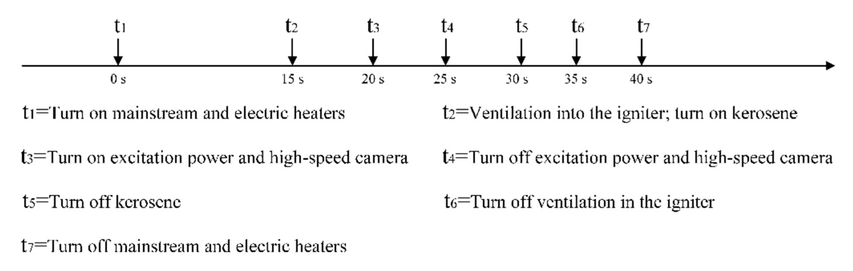
2.3. Hyperburner Ignition Experimental System
3. Experimental Results and Analysis
3.1. Electrical Characteristics of the Gliding Arc Plasma Igniter
3.2. Outlet Flow Field Distribution of Gliding Arc Plasma Igniter
3.3. Jet Characteristics of the Gliding Arc Plasma Igniter
3.4. Ignition Characteristics of the Gliding Arc Plasma Igniter in the Hyperburner
3.4.1. Influence of Δp on Ignition Characteristics
3.4.2. Influence of Oil–Gas Ratio on Ignition Characteristics
4. Conclusions and Outlook
- (1)
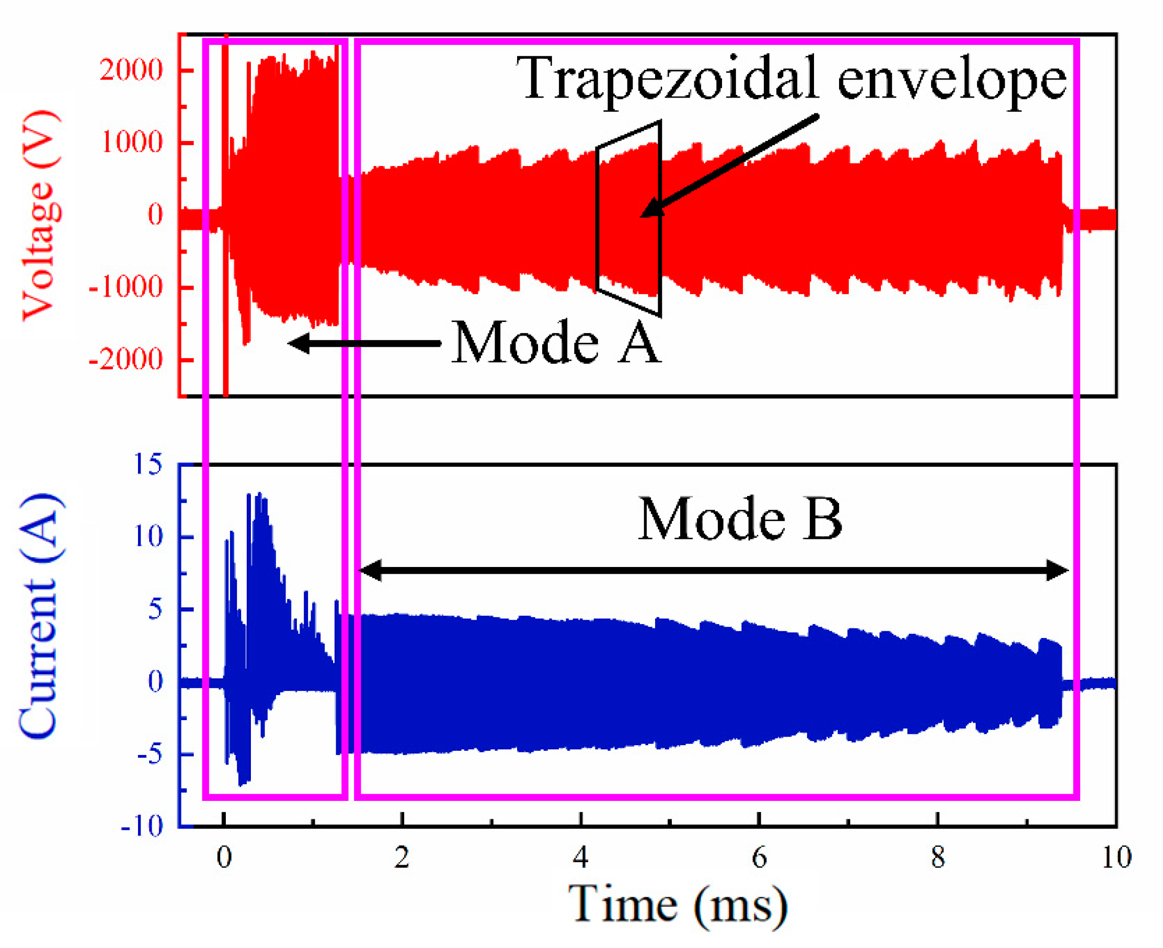
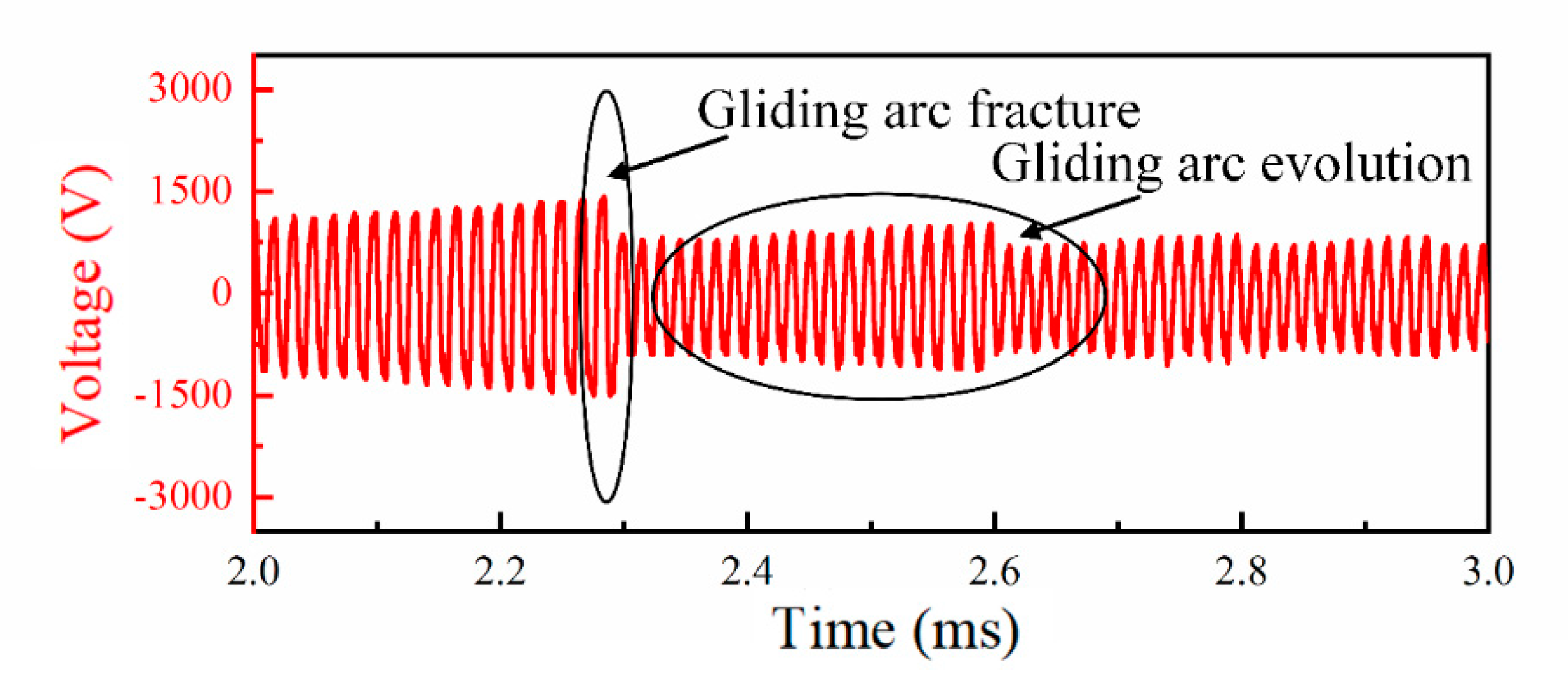
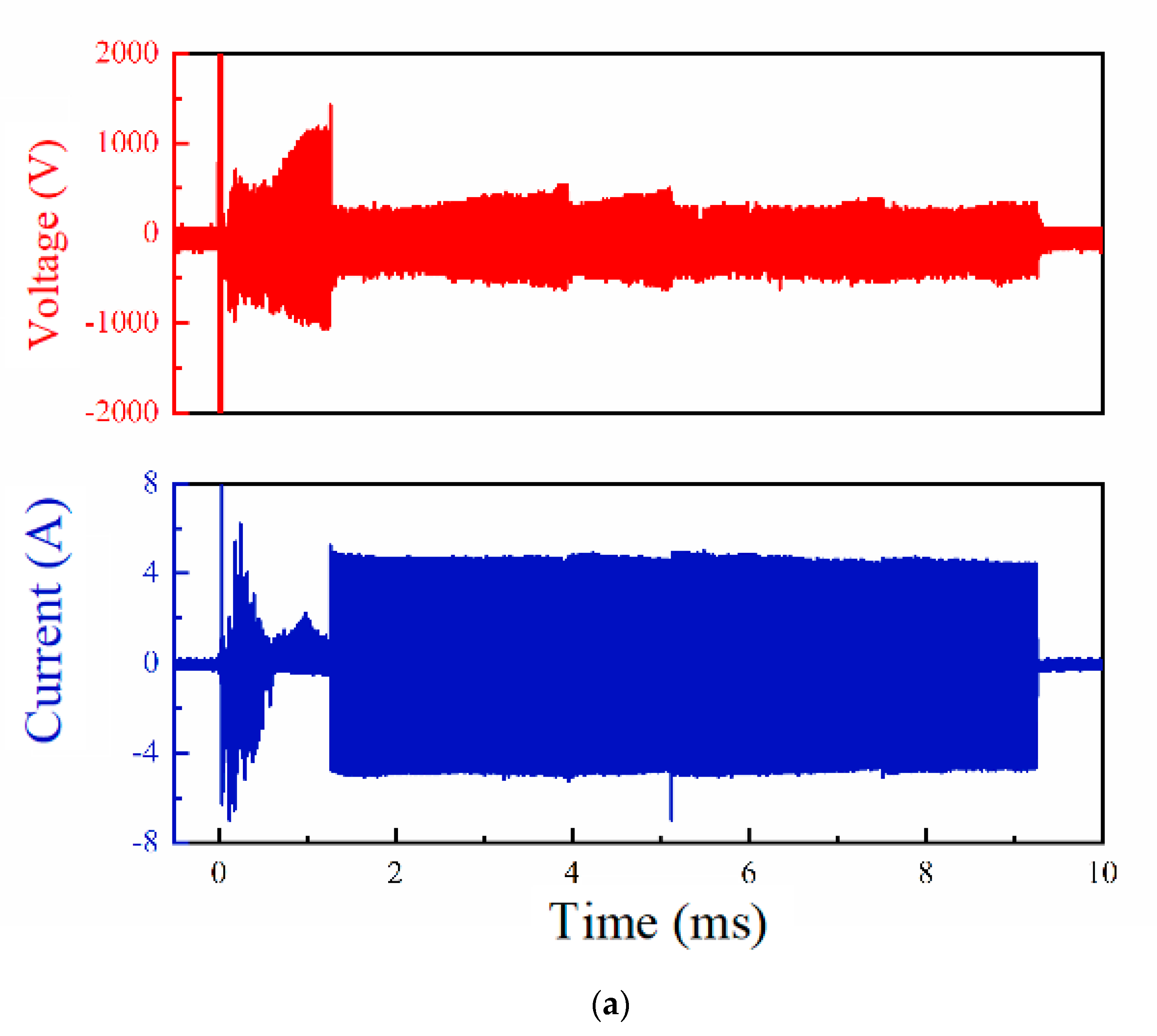
- With the increase in Δp, the frequency of the trapezoidal envelope in the voltage and current waveforms increases, which means the frequency of the evolution and fracture of the gliding arc increases. When Δp is 550 Torr, it will affect the continuous discharge time of the gliding arc. There exists a period where the voltage is normal and the current is equal to 0 A. The appearance of this phenomenon may weaken the ignition effect of the gliding arc.
- (2)
- The gas ejected from the cathode channel of the gliding arc plasma igniter driven by pressure difference will form a swirl sheath to protect the gliding arc at the igniter outlet. As Δp increases, the maximum velocity of the swirl sheath and the protective effect of the swirl sheath improve. The addition of Δp will raise the maximum airflow velocity of the gas ejected from the cathode channel, which helps to enhance the rigidity of the gliding arc.
- (3)
- The length of the gliding arc jet tends to increase first and then decrease with the increase in Δp. When Δp is 50 Torr, the jet length reaches a maximum value of 31 mm while the exit velocity of the igniter (about 9 m/s) and the maximum velocity of the swirl sheath (about 6 m/s) are relatively small, indicating the gliding arc rigidity is relatively poor. The jet length of the gliding arc and the rigidity of the gliding arc should be considered in detail when the gliding arc is used in the ignition application of the hyperburner.
- (4)
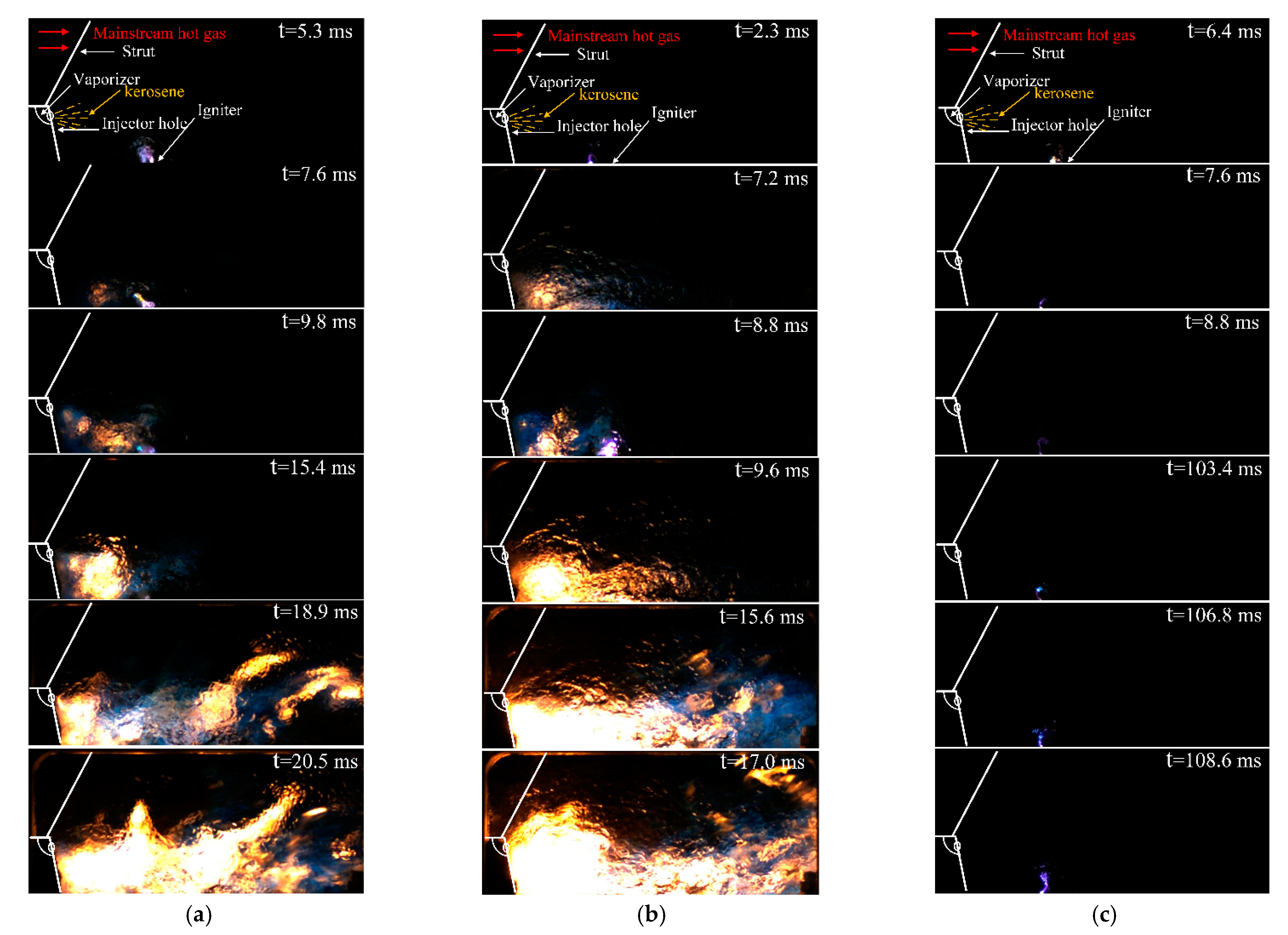
- The value of Δp can affect the lean ignition limit and ignition delay time of the hyperburner. When the incoming flow is 0.1 Ma and the inlet temperature is 300 K, the lean ignition limit can be widened by 37.5% when a Δp value of 350 Torr is compared with a Δp value of 550 Torr. When the inflow velocity is 0.1 Ma, the total inflow temperature is 420 K, and the oil–gas ratio is 0.0043, the ignition delay time is 17 ms when Δp is 350 Torr, and the flame propagation process is the quickest. Compared with the ignition when Δp is 50 Torr where the delay time is 20.5 ms, the ignition delay time is shortened by 17% when Δp is 350 Torr.
Author Contributions
Funding
Institutional Review Board Statement
Informed Consent Statement
Data Availability Statement
Conflicts of Interest
Nomenclature
| Symbol | Description | Unit |
| Δp | Igniter inlet and outlet pressure difference | Torr |
| Ma | Mach number | - |
| T* | Hyperburner inlet total temperature | K |
References
- Chen, D.G. Brief Introduction of Hyperson Flight and TBCC Concept. Aeroengine 2006, 32, 4. (In Chinese) [Google Scholar]
- Chen, M.; Tang, H.L.; Zhu, D.M.; Zhu, Z. Hypersonic combined cycle engine concept with tandem layout. J. Beijing Univ. Aeronaut. Astronaut. 2007, 33, 4. (In Chinese) [Google Scholar]
- Marshall, A.; Gupta, A.; Lavelle, T.; Lewis, M. Critical Issues in TBCC Modeling. In Proceedings of the 40th AIAA/ASME/SAE/ASEE Joint Propulsion Conference and Exhibit, Fort Lauderdale, FL, USA, 11–14 July 2004. [Google Scholar]
- Wang, Z.X.; Liu, Z.W.; Wang, M.; Li, B. Future Development and Application Prospect of Turbine Based Combined Cycle Engine. Aeroengine 2013, 39, 6. (In Chinese) [Google Scholar]
- Mcnelis, N.; Bartolotta, P. Revolutionary Turbine Accelerator (RTA) Demonstrator. In Proceedings of the AIAA/CIRA 13th International Space Planes and Hypersonics Systems and Technologies Conference, Capua, Italy, 16–20 May 2005. [Google Scholar]
- Jin, J.; Chen, M. Brief Introduction on Technology Development of Turbine Based Combined Cycle Engine. Aeronaut. Manuf. Technol. 2014, 9, 32–35. (In Chinese) [Google Scholar]
- Stueber, T.J.; Vrnak, D.R.; Le, D.K.; Ouzts, P.J. Control Activity in Support of NASA Turbine Based Combined Cycle (TBCC) Research; NASA/TM 2010-216109; NASA: Washington, DC, USA, 2010. [Google Scholar]
- Anderson, E.; Lopata, J. Using a modified SR-71 aircraft and air-launched expendable rockets to place small payloads into orbit. In Proceedings of the Joint Propulsion Conference & Exhibit, Lake Buena Vista, FL, USA, 1–3 July 1996. [Google Scholar]
- Kloesel, K.J.; Ratnayake, N.A.; Clark, C.M. A Technology Pathway for Airbreathing, Combined-Cycle, Horizontal Space Launch Through SR-71 Based Trajectory Modeling. In Proceedings of the 17th AIAA International Space Planes and Hypersonic Systems and Technologies Conference, San Francisco, CA, USA, 11–14 April 2011. [Google Scholar]
- Wang, D.; Chen, W.; Shao, J.W.; Hu, Y.C. Development of turbo-stamping combined propulsion technology and its application in near space. Aerodyn. Missile J. 2008, 8, 55–59. (In Chinese) [Google Scholar]
- Lee, J.H.; Winslow, R.; Buehrle, R.J. The GE-NASA RTA Hyperburner Design and Development; NASA/TM 2005-213803; NASA: Washington, DC, USA, 2005. [Google Scholar]
- Dimitrakellis, P.; Faubert, F.; Wartel, M.; Gogolides, E.; Pellerin, S. Plasma Surface Modification of Epoxy Polymer in Air DBD and Gliding Arc. Processes 2022, 10, 104. [Google Scholar] [CrossRef]
- Pang, Y.; Hammer, T.; Müller, D.; Karl, J. Investigation of Nonthermal Plasma Assisted Charcoal Gasification for Production of Hydrogen-Rich Syngas. Processes 2019, 7, 114. [Google Scholar] [CrossRef]
- Brande, W.T., IV. The Bakerian Lecture: On Some New Electro-Chemical Phenomena. Philos. Trans. R. Soc. Lond. 1814, 104, 51–61. [Google Scholar]
- Jacobsen, L.S.; Carter, C.D.; Jackson, T.A.; Williams, S.; Barnett, J.; Bivolaru, D.; Kuo, S.; Tam, C.-J.; Baurle, R.A. Plasma-Assisted Ignition in Scramjets. J. Propuls. Power 2008, 24, 641–654. [Google Scholar] [CrossRef]
- Huang, S.; Wu, Y.; Song, H.; Zhu, J.; Zhang, Z.; Song, X.; Li, Y. Experimental investigation of multichannel plasma igniter in a supersonic model combustor. Exp. Therm. Fluid Sci. 2018, 99, 315–323. [Google Scholar] [CrossRef]
- Starikovskaia, S.M. Plasma assisted ignition and combustion. J. Phys. D-Appl. Phys. 2006, 39, R265–R299. [Google Scholar] [CrossRef]
- Lin, B.; Wu, Y.; Zhang, Z.; Bian, D.; Jin, D. Ignition enhancement of lean propane/air mixture by multi-channel discharge plasma under low pressure. Appl. Therm. Eng. 2019, 148, 1171–1182. [Google Scholar] [CrossRef]
- Ju, Y.G.; Sun, W.T. Plasma assisted combustion: Dynamics and chemistry. Prog. Energy Combust. Sci. 2015, 48, 21–83. [Google Scholar] [CrossRef]
- Song, F.; Wu, Y.; Xu, S.; Jin, D.; Jia, M. N-decane decomposition by microsecond pulsed DBD plasma in a flow reactor. Int. J. Hydrogen Energy 2019, 44, 3569–3579. [Google Scholar] [CrossRef]
- Starikovskii, A.Y. Plasma supported combustion. Proc. Combust. Inst. 2005, 30, 2405–2417. [Google Scholar] [CrossRef]
- Czernichowski, A.; Nassar, H.; Ranaivosoloarimanana, A.; Fridman, A.A.; Simek, M.; Musiol, K.; Pawelec, E.; Dittrichova, L. Spectral and Electrical Diagnostics of Gliding Arc. Acta Phys. Pol. A 1996, 89, 595–603. [Google Scholar] [CrossRef]
- Fridman, A.; Gutsol, A.; Gangoli, S.; Ju, Y.; Ombrello, T. Characteristics of Gliding Arc and Its Application in Combustion Enhancement. J. Propuls. Power 2008, 24, 1216–1228. [Google Scholar] [CrossRef]
- Sun, W.; Uddi, M.; Ombrello, T.; Won, S.H.; Carter, C.; Ju, Y. Effects of Non-Equilibrium Plasma Discharge on Counterflow Diffusion Flame Extinction. Proc. Combust. Inst. 2011, 33, 3211–3218. [Google Scholar] [CrossRef]
- Sun, W.; Uddi, M.; Won, S.H.; Ombrello, T.; Carter, C.; Ju, Y. Kinetic Effects of Non-Equilibrium Plasma-Assisted Methane Oxidation on Diffusion Flame Extinction Limits. Combust. Flame 2012, 159, 221–229. [Google Scholar] [CrossRef]
- Ombrello, T.; Qin, X.; Ju, Y.; Gutsol, A.; Fridman, A.; Carter, C. Combustion Enhancement Via Stabilized Piecewise Nonequilibrium Gliding Arc Plasma Discharge. AIAA J. 2006, 44, 142–150. [Google Scholar] [CrossRef]
- Ombrello, T.; Won, S.H.; Ju, Y.; Williams, S. Flame Propagation Enhancement by Plasma Excitation of Oxygen. Part I: Effects of O3. Combust. Flame 2010, 157, 1906–1915. [Google Scholar] [CrossRef]
- Leonov, S.; Yarantsev, D.; Napartovich, A.; Kochetov, I. Plasma-Assisted Ignition and Flameholding in High-Speed Flow. In Proceedings of the 44th AIAA Aerospace Sciences Meeting and Exhibit, Reno, NV, USA, 9–12 January 2006; p. 563. [Google Scholar]
- Leonov, S.; Houpt, A.; Elliott, S.; Hedlund, B. Ethylene Ignition and Flameholding by Electrical Discharge in Supersonic Combustor. J. Propuls. Power 2017, 34, 499–509. [Google Scholar] [CrossRef]
- Leonov, S.B.; Yarantsev, D.A. Plasma-induced ignition and plasma-assisted combustion in high-speed flow. Plasma Sources Sci. Technol. 2006, 16, 132–138. [Google Scholar] [CrossRef]
- Pinto, A.J.; Sagás, J.C.; Lacava, P.T. Repetition frequency of a DC gliding arc discharge in plasma-assisted fuel-rich combustion. Europhys. Lett. 2018, 123, 65001. [Google Scholar] [CrossRef]
- Jia, M.; Lin, D.; Huang, S.; Zhang, Z.; Cui, W.; Wang, W. Experimental investigation on gliding arc plasma ignition in double-head swirling combustor. Aerosp. Sci. Technol. 2021, 113, 106726. [Google Scholar] [CrossRef]
- Chen, W.; Jin, D.; Cui, W.; Huang, S. Characteristics of Gliding Arc Plasma and Its Application in Swirl Flame Static Instability Control. Processes 2020, 8, 684. [Google Scholar] [CrossRef]


Publisher’s Note: MDPI stays neutral with regard to jurisdictional claims in published maps and institutional affiliations. |
© 2022 by the authors. Licensee MDPI, Basel, Switzerland. This article is an open access article distributed under the terms and conditions of the Creative Commons Attribution (CC BY) license (https://creativecommons.org/licenses/by/4.0/).
Share and Cite
Cheng, X.; Song, H.; Sun, J.; Cui, W.; Zhang, Z.; Jia, M.; Jin, D.; Zhu, Y. Experimental Investigation on Ignition of Hyperburner Based on Gliding Arc Plasma Igniter Driven by Pressure Difference. Processes 2022, 10, 1886. https://doi.org/10.3390/pr10091886
Cheng X, Song H, Sun J, Cui W, Zhang Z, Jia M, Jin D, Zhu Y. Experimental Investigation on Ignition of Hyperburner Based on Gliding Arc Plasma Igniter Driven by Pressure Difference. Processes. 2022; 10(9):1886. https://doi.org/10.3390/pr10091886
Chicago/Turabian StyleCheng, Xinyao, Huimin Song, Jiulun Sun, Wei Cui, Zhibo Zhang, Min Jia, Di Jin, and Yifei Zhu. 2022. "Experimental Investigation on Ignition of Hyperburner Based on Gliding Arc Plasma Igniter Driven by Pressure Difference" Processes 10, no. 9: 1886. https://doi.org/10.3390/pr10091886