1. Introduction
Centrifugal prefabricated pumping station is a centrifugal pump, prefabricated cylinder, piping and valves, and other components combined into one power lifting device, and the traditional concrete pumping station, compared to the prefabricated pumping station, is simple and easy to install, has a short construction time, has a small footprint, has good savings in land resources, and has good economic benefits. The geometric parameters of prefabricated pumping stations have an important impact on the hydraulic performance and internal flow characteristics of prefabricated pumping stations, and the lack of relevant theory restricts their efficient, stable, and safe operation, so it is necessary to carry out in-depth research on them.
A few scholars have studied the integrated prefabricated pumping station; discussed its use efficiency [
1,
2], flow characteristics [
3], geometric parameters of pump installation [
4], water and sediment flow [
5,
6]; put forward positive opinions on the engineering application of the integrated prefabricated pumping station; and studied its flow characteristics; however, these pieces of work did not involve the optimization of specific structural parameters. The research topic of this paper is a centrifugal prefabricated pumping station, in which the key pump unit equipment is the centrifugal pump. Relevant scholars have studied the flow characteristics of centrifugal pump and the optimization of geometric parameters of a single pump, such as the influence of blade tip clearance on the hydraulic performance and internal flow characteristics of centrifugal pump [
7,
8], the influence of increasing splitter blade on the hydraulic performance of centrifugal pump [
9,
10], the influence of volute with different parameters on the hydraulic performance of centrifugal pump [
11,
12], and different speeds [
13]. The influence of different blade thickness [
14] impacts on the hydraulic performance and internal flow characteristics of centrifugal pumps. Some scholars also used orthogonal analysis methods to optimize the geometric parameters of centrifugal pumps and discussed the influence of geometric parameters on their hydraulic performance and internal flow characteristics [
15,
16,
17,
18,
19]. However, the research of relevant scholars focused on the geometric parameters of single centrifugal pumps, and the optimization design of geometric parameters of integrated prefabricated pumping stations was less involved. The geometric parameters of the prefabricated barrel of the integrated prefabricated pumping station play an important role in the performance of the centrifugal pump, so it is necessary to carry out relevant research work.
Based on orthogonal optimization, this paper optimizes the design of prefabricated barrels under the condition of double pump operation of centrifugal prefabricated pumping stations, in order to improve the hydraulic performance of prefabricated pumping station and improve the internal flow pattern of prefabricated pumping stations. The research of this paper has certain theoretical significance and engineering application value.
2. 3D Modelling and Numerical Calculation Settings
2.1. Calculation Model
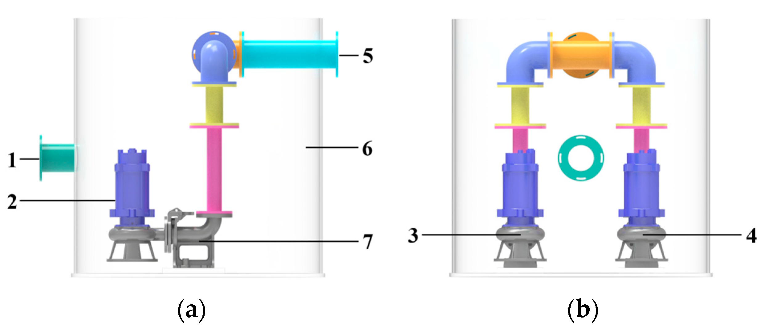
In this paper, the original scheme and optimal design scheme are modelled in 3D by SolidWorks software for centrifugal prefabricated pumping stations, where the height of the prefabricated barrel was
L = 1 m, the diameter of the prefabricated barrel was
D = 1 m, the diameter of the inlet and outlet was
R = 100 mm, the pump is a submersible centrifugal pump with impeller diameter was
d = 100 mm, the number of blades is three, the speed of the single pump was
n = 2900 r/min, and the 3D structure is shown in
Figure 1.
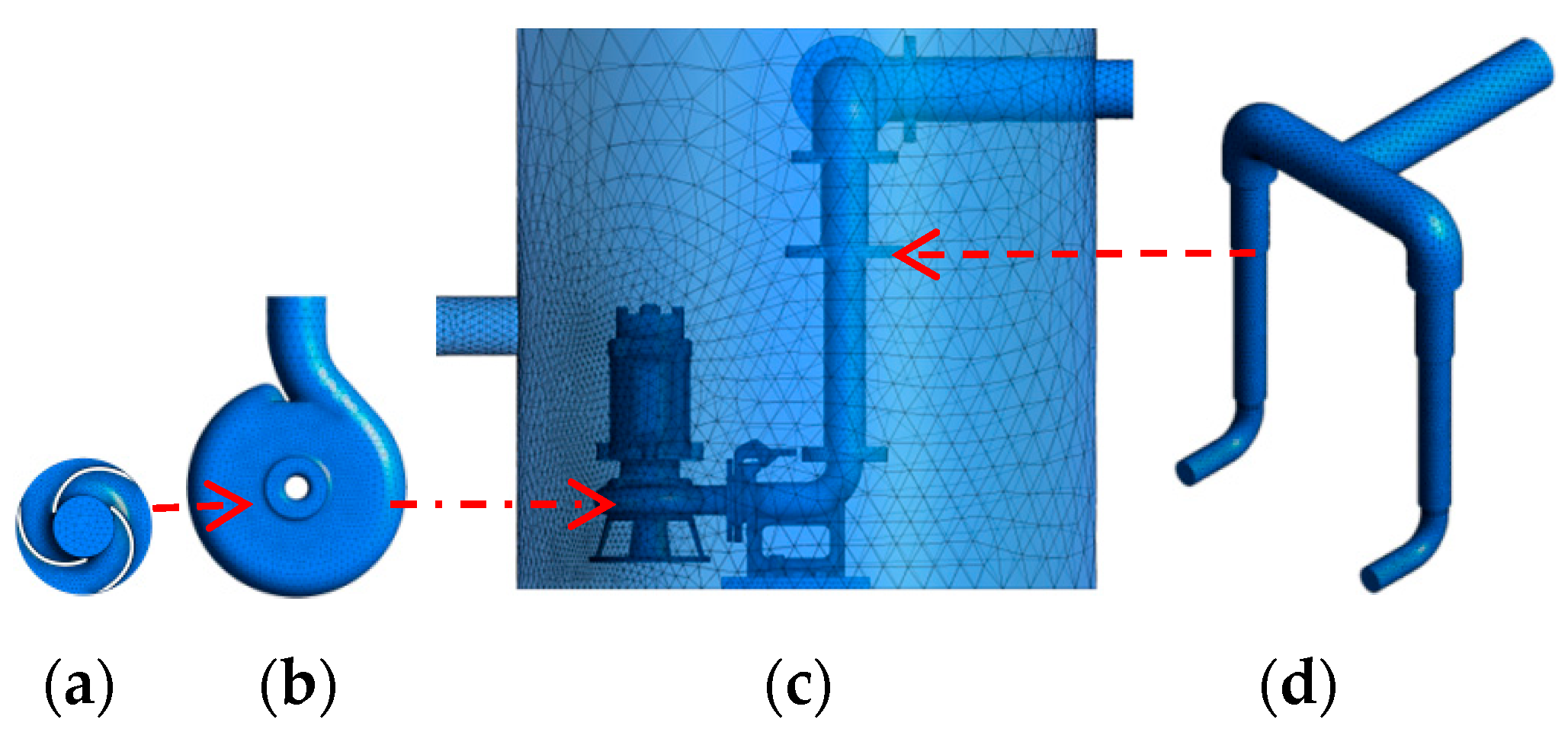
2.2. Meshing
In this paper, internal fluid passages of each design scheme are extracted, and then 3D models of original scheme and orthogonal optimization scheme are meshed by Mesh software. The mesh calculation area is divided into four parts: intake section, prefabricated bucket, impeller, and outlet section. Because flanges, motors, and coupling details are considered in the structure, the model is more complex and the tetrahedral mesh is more effective in terms of applicability. In this paper, tetrahedral unstructured mesh is used to divide the calculation area. The grid of each calculation area of centrifugal prefabricated pumping station is shown in
Figure 2.
In this paper, the original centrifugal prefabricated pumping station scheme is numerically calculated using seven different grid numbers and the efficiency of the centrifugal prefabricated pumping station is used as the judging index. As can be seen from
Table 1, after the grid number reaches 3.26 million, the efficiency value basically remains unchanged. In this paper, considering the computer performance and the accuracy of the calculation results, we finally choose to use the grid number of 3.26 million to carry out the subsequent numerical calculation work.
2.3. Boundary Conditions and Turbulence Model
For each design scheme of centrifugal prefabricated pumping station, the inlet condition is set as total pressure, the pressure is set as one atmosphere, and the outlet condition is set as normal speed. Solid wall condition is set as non-slip boundary condition, impeller surface condition is set as rotating wall condition, prefabricated barrel, volute and outlet section surface condition is set as stationary wall condition, application boundary is set as non-slip. In the calculation area, the calculation area of intake section, prefabricated barrel, spiral case, and outlet section is set as stationary area and the calculation area of the impeller is set as rotating area. Frozen rotor for dynamic–static interface. In the numerical calculation, the rotating shafts of A and B pumps are different, and the rotating shafts are determined in the vertical direction of the respective impeller center.
In this paper, several common calculation models are used to numerically calculate the initial scheme of centrifugal prefabricated pumping station under the design condition (
Q = 33.93 m
3/h), and the uniformity of flow velocity distribution at the outlet section of the prefabricated barrel of prefabricated pumping station is calculated, among which the uniformity of outlet flow velocity distribution, corresponding to SST
k-ω model,
k-ε model, RNG
k-ε model, and
k-ω model are 97.5934%, 97.7239%, 97.7360%, and 97.5928% respectively. The difference between the uniformity of flow velocity distribution of different models is within 0.15%; there is no significant difference, so the N-S equation based on Reynolds time-averaged method is chosen in this paper, and the SST
k-ω [
20] mathematical model is used as the calculation model for the turbulence model, and the automatic function is used in the boundary layer, which can better capture the flow in the boundary layer.
2.4. Calculation Formula
The head calculation formula of centrifugal prefabricated pumping station in each design scheme is:
In the equation, the first item on the right side is the total pressure at the outlet section of the prefabricated barrel and the second item is the total pressure at the inlet section of the prefabricated barrel.
Q-flow rate, m3/s; H1, H2—elevation of inlet and outlet section of prefabricated barrel, m.
S1 and S2—section area of inlet and outlet of prefabricated barrel; u1, u2—flow rate at each point of inlet and outlet of prefabricated barrel, m/s; ut1, ut2—normal component of flow velocity at each point of inlet and outlet section of prefabricated barrel, m/s;
P1, P2—static pressure at each point of inlet and outlet section of prefabricated barrel, Pa; g—gravity acceleration, m/s2.
The efficiency calculation formula of centrifugal prefabricated pump station is:
In formula N1—shaft power of pump A and shaft power of N2—pump B.
The calculation formula for shaft power of centrifugal prefabricated pump station is:
In formula: T—torque, N·m; n—speed, r/min.
3. Centrifugal Prefabricated Pumping Station Test
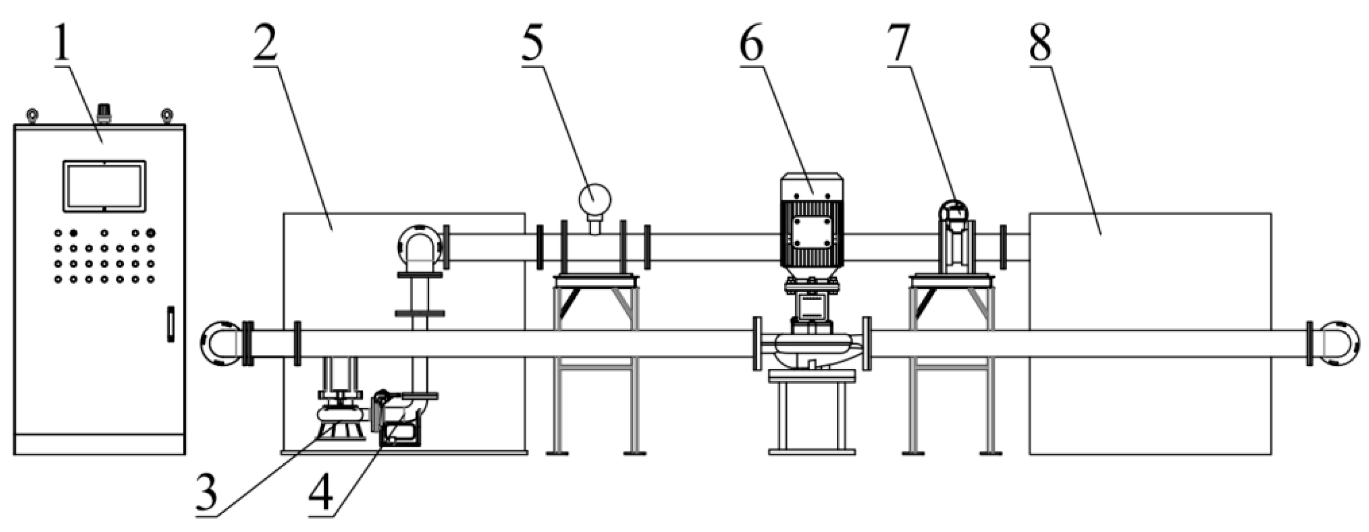
Centrifugal prefabricated pumping station test bench has the following parts: prefabricated barrel, water return tank, submersible centrifugal pump, coupler, inlet and outlet pipes, electromagnetic flow meter, pipeline pump, and PLC frequency control cabinet. The total length of the test bench is about 5 m, the diameter of the pipe is 100 mm, and the whole is a circulatory system. The whole test bench is made of acrylic material to achieve transparent visualization and to clearly observe the flow of water inside the centrifugal pumping station.
Figure 3 shows a sketch of the centrifugal prefabricated pumping station test bench, and
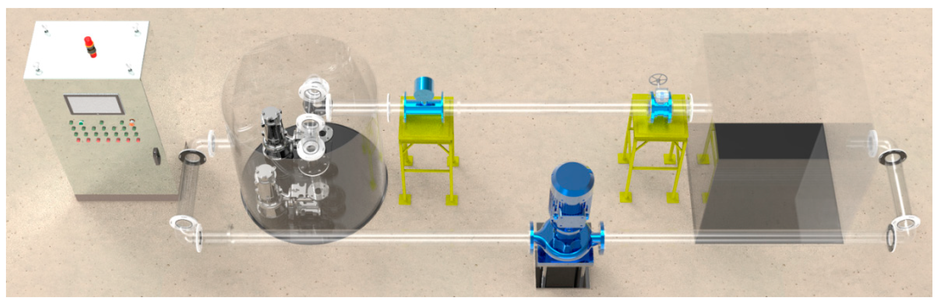
Figure 4 shows a 3D model of the centrifugal prefabricated pumping station test bench.
Figure 5 shows the physical diagram of the centrifugal prefabricated pumping station test bench. The flow rate is measured by electromagnetic flowmeter (ZEF-DN100, range 0~120 m
3/h, accuracy ±0.5%), and the flow state is captured by high-speed camera (OLYMPUS i-SPEED 3, working range 2000 fps full resolution, accuracy ±1 μs).
4. Prefabricated Barrel Orthogonal Optimization Design Analysis
Geometric parameters have a great influence on the hydraulic performance of centrifugal prefabricated pumping stations, as well as on the internal flow regime. Due to the correlation of geometric parameters, changing a single factor changes the effect of other factors on the hydraulic performance and internal flow characteristics of the prefabricated pumping stations. Orthogonal optimization is a design method to conduct multi-factor experiments by means of orthogonal tables, and the optimal combination of each influencing factor is finally determined by analyzing the optimization results. In this paper, we will investigate the improvement effect of geometric parameters of prefabricated pumping stations on the hydraulic performance and internal flow field of centrifugal prefabricated pumping stations by combining numerical calculation and orthogonal optimization to design an optimal scheme for the geometric parameters of prefabricated pumping stations.
4.1. Selection of Orthogonal Optimization Factors
In order to be able to better optimize the design of centrifugal prefabricated pumping stations, five typical parameters of pump spacing
S, inlet height
H, overhang height
Z, center distance
Y, and inlet radius
R are selected as the factors for orthogonal optimization in this paper. In this paper, the horizontal distance between the centers of the two pump impellers is defined as the pump spacing
S, the vertical distance from the center of the inlet to the bottom of the barrel is defined as the inlet height
H, the distance from the center of the pump impeller to the bottom is defined as the overhang height
Z, the vertical projection distance from the horizontal center point of the two pump impellers to the center of the prefabricated barrel is defined as the center distance
Y, and the radius of the inlet is defined as the inlet radius
R. The parameters are schematically shown in
Figure 6.
4.2. Orthogonal Optimization Design
In this paper, an orthogonal table with five factors and four levels of L16 is designed, and the factors and levels are shown in
Table 2 and
Table 3, where the factor designations A, B, C, D, and E represent pump spacing
S, inlet height
H, overhang height
Z, center distance
Y, and inlet radius
R, respectively. The initial scheme,
S = 470 mm,
H = 445 mm,
Z = 149 mm,
Y = 265 mm,
R = 50 mm, considering the difficulty of processing and making and the convenience of manufacturing, try to make the parameters integer when determining the level value in this paper, and also considering the actual operation of centrifugal prefabricated pumping stations, should make the inlet height as low as possible, which is conducive to the water flow into the prefabricated barrel, and thus the inlet radius can be slightly increased. Also conducive to the inlet flow, this paper orthogonal optimization in the design working condition (
Qd = 33.93 m
3/h), the evaluation index is efficiency
η.
The above 16 groups of optimization schemes were modeled in 3D, meshed, and calculated numerically by CFD, and then the results of the 16 groups of numerical calculations were analyzed, and the optimization results are shown in
Table 4.
4.3. Analysis of Orthogonal Optimization Results
Using the intuitive analysis method, from the visual analysis of the optimization result data in
Table 4, it can be obtained that the index of scheme 15 is the highest, that is, the pumping station efficiency is the highest, which is 64.69%, which is 0.70% higher than the original scheme. It can be seen from the table that only scheme 8 and 11 have a 63.96% lower efficiency than the initial scheme, and the pumping station efficiency of the other schemes is higher than the initial scheme, indicating that it is feasible to improve the efficiency of the prefabricated pumping station by optimizing the geometric parameters of the prefabricated pumping station.
The extreme difference is the difference between the maximum and minimum values in the mean of the sum of the levels of each influencing factor, that is,
R = max{
k1,
k2,
k3,
k4} − min{
k1,
k2,
k3,
k4}, whose value size can reflect the degree of influence of each factor on the efficiency of the prefabricated pumping station. From
Table 4, it can be seen that the size of the extreme difference in efficiency of the pumping station is D > A > C > E > B. Therefore, it can be determined that the order of the influencing factors is center distance
Y, pump spacing
S, overhang height
Z, inlet radius
R, and inlet height
H. The center distance
Y is the key factor, pump spacing
S, overhang height
Z, and inlet radius
R both are general factors, and inlet height
H is a secondary factor.
In order to more intuitively represent the relationship between the influence of each influencing factor on the efficiency of prefabricated pumping stations, the factor influence trend diagram of each influencing factor is drawn, the horizontal coordinate of the trend diagram is the level of each factor, the vertical coordinate is the average value of the sum of the efficiency of prefabricated pumping stations at each level, the relationship between each factor and level, and the efficiency of prefabricated pumping stations is shown in
Figure 7.
As can be seen from
Figure 7, the factor in the figure (a) is the pump spacing, the efficiency of prefabricated pumping station decreases and then increases with the increase in pump spacing, reaching the maximum at 300 mm (3
d); the factor in the figure (b) is the suspended height, the efficiency of prefabricated pumping station increases and then decreases and then increases with the increase in suspended height, reaching the maximum at 250 mm (2.5
d); the factor in the figure (c) is the center spacing, the efficiency of prefabricated pumping stations increases and then decreases and then increases with the increase in center spacing, reaching a maximum at 100 mm (1.0
d); the factor in figure (d) is the inlet height: the efficiency of prefabricated pumping station decreases and then increases with the increase in inlet height, reaching the maximum at 700 mm (7.0
d); the factor in figure (e) is the inlet radius, the efficiency of prefabricated pumping station increases and then decreases with the increase in inlet radius, reaching the maximum at 100 mm (1.0
d).Therefore, it is favorable to improve the efficiency of the prefabricated pumping station when the pump spacing is around 300 mm (3.0
d), the suspended height is 250 mm (2.5
d), the center spacing is 100 mm (1.0
d), the inlet height is 700 mm (7.0
d), and the inlet radius is 100 mm (1.0
d). This scheme is not in the orthogonal optimization table, and by numerical calculation of this scheme, it is obtained that the efficiency of the prefabricated pumping station under this scheme is 63.51%, which is lower than the efficiency of the initial scheme and the orthogonal optimization scheme 15.
From the above analysis, the results of the orthogonal table test under the comprehensive design working conditions and the trend graph analysis, the optimal solution for this orthogonal optimization is 550 mm (5.5 d) for the pump spacing, 300 mm (3.0 d) for the suspended height, 100 mm (1.0 d) for the center spacing, 700 mm (7.0 d) for the inlet height, and 75 mm (0.75 d) for the inlet radius; at this time, the prefabricated pumping station efficiency is 64.69%, which is about 0.70% higher than the original scheme.
ANOVA can be used to determine if there are significant differences in the results of orthogonal calculations. The purpose of the analysis is to investigate the factors that have a significant effect on the performance of centrifugal prefabricated pumping stations, the interaction between the factors, and the optimum level of significant influence on the factors. Based on the F-values, it can be seen that the effect of the change in the level of factor D and factor A on the results showed highly significant, and the effect of the change in the level of factor C and factor B on the results showed significant. ANOVA as shown in
Table 5.
4.4. Comparison Analysis of Hydraulic Performance before and after Optimization
Through numerical calculation of different flow rates of prefabricated pumping stations before and after optimization, the energy characteristics of centrifugal prefabricated pumping stations were obtained, as shown in
Table 6, and the performance comparison curves are shown in
Figure 8.
It can be obtained from
Figure 8 that under the small flow condition (0.33
Qd~1.00
Qd), the efficiency and head before and after optimization do not change much, and under the design condition (
Qd = 33.93 m
3/h); the efficiency of prefabricated pumping station before optimization is 63.96%, and after optimization, the efficiency is 64.69%, which is 0.73% higher; the head of prefabricated pumping station before optimization is 8.66 m, and after optimization, the head is 8.76 m, which is improved by 0.10 m, under the high flow condition (1.00
Qd~2.33
Qd); the optimized efficiency is significantly improved; the maximum rise is 4.86%; the average range is 2.69%. After optimization the centrifugal prefabricated pumping station high efficiency zone has been widened, and the overall head has been increased. Overall, the optimized centrifugal prefabricated pumping station has better energy characteristics and can provide a better economic benefit.
4.5. Comparison and Analysis of Internal Flow Characteristics before and after Optimization
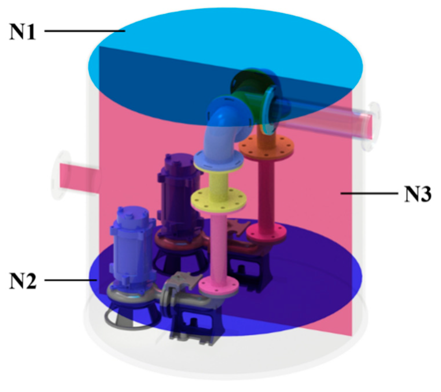
In this paper, the characteristic section N1-N3 is selected, as shown in
Figure 9, where N1 is the top section of liquid level in prefabricated barrel, N2 is the center section of impeller of centrifugal pump, and N3 is the vertical and longitudinal section of fluid in prefabricated barrel. The streamline and velocity distribution on N1-N3 section of centrifugal prefabricated pumping stations before and after optimization (
Qd = 33.93 m
3/h) are extracted, as shown in
Figure 10,
Figure 11 and
Figure 12. The internal red line of the prefabricated barrel at different times under design conditions (
Qd = 33.93 m
3/h) is shown in
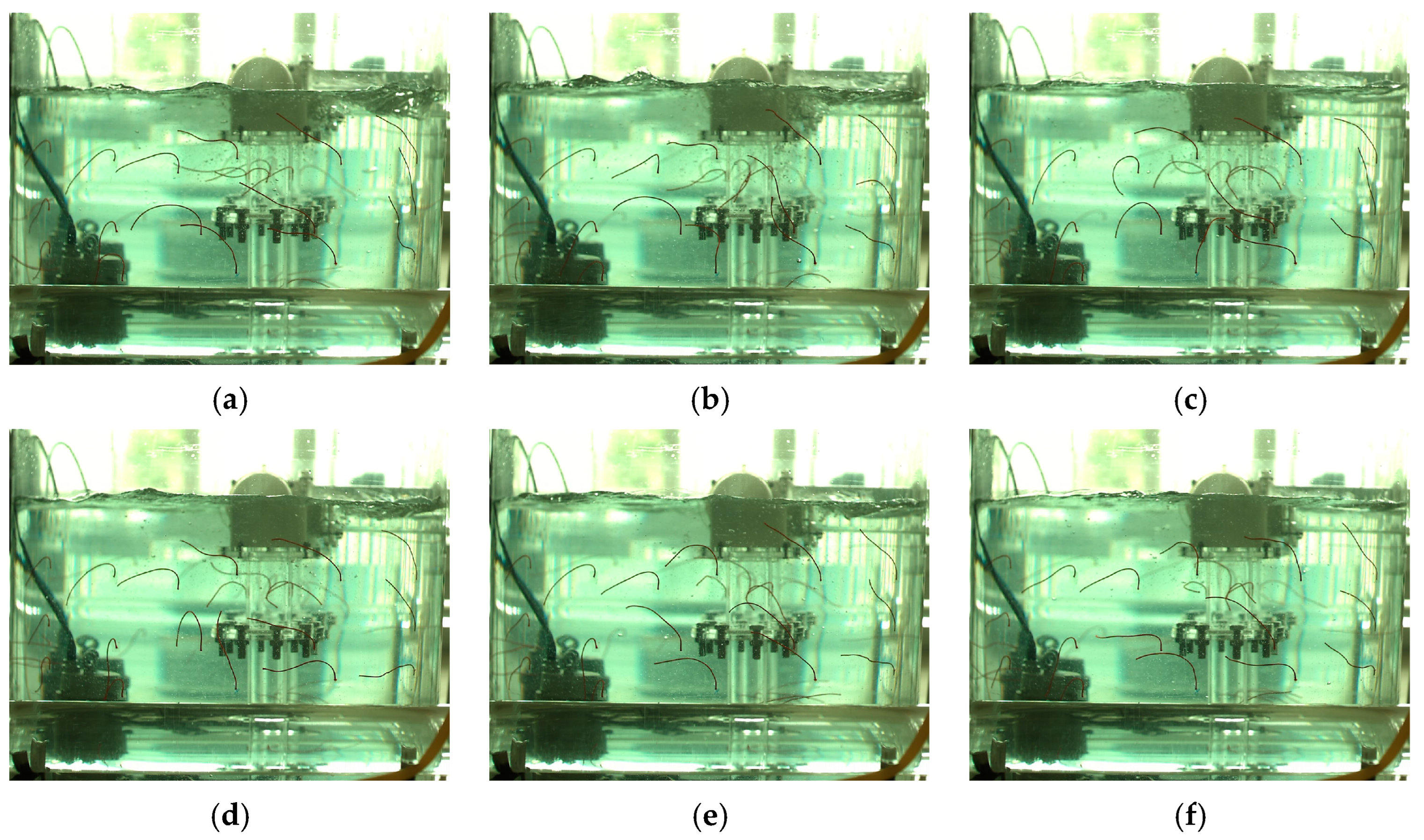
Figure 13 for high-speed camera photography.
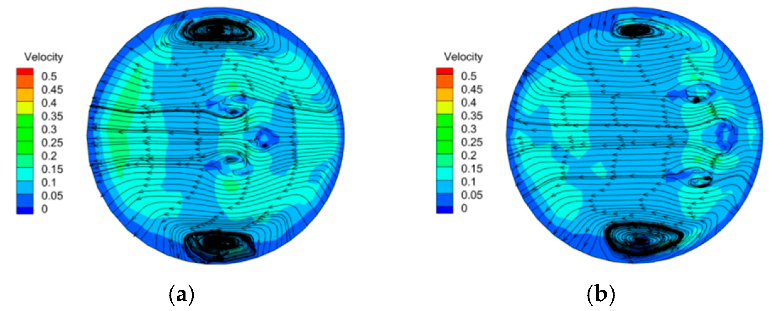
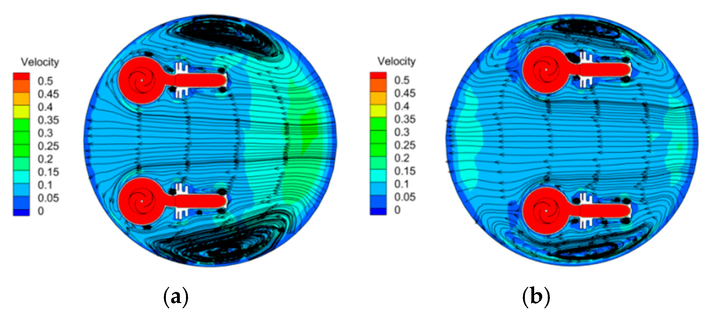
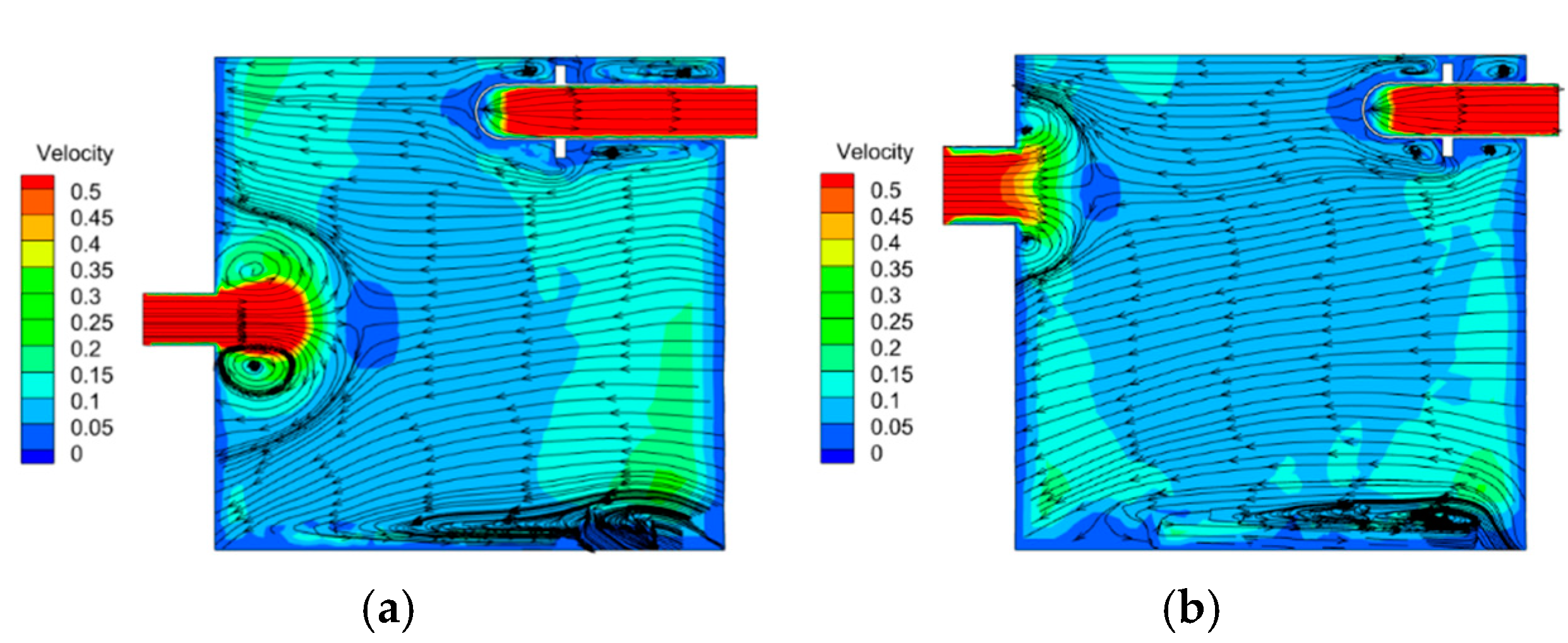
Through the comparative analysis of
Figure 10,
Figure 11 and
Figure 12, it can be seen that the area of the sidewall vortex area on the N1 section has been reduced after optimization, the uniformity of flow velocity on the section has been improved, and the area occupied by the high-speed zone has been reduced. In the N2 cross-section, the sidewall vortex is also reduced after optimization, the uniformity of flow velocity in the cross-section is obviously improved, and there is only a part of high-speed area in the cross-section near the inlet and outlet side. From the N3 cross-section, the flow velocity and streamline distribution are similar before and after optimization, but the area of the backflow vortex at the inlet is smaller after optimization, and the bottom vortex has been improved after optimization. Overall, the flow field distribution in the prefabricated barrel of the optimized centrifugal prefabricated pumping station was improved, compared with that before the optimization, and the fluid stability was improved, and the phenomenon of water flow collision in the center of the prefabricated barrel was reduced, and the flow pattern after optimization is generally better than that before optimization.
Through the test shooting different moments of the internal tracer red line,
Figure 13 can be obtained; the tracer red line swings from the red line of water outlet to the direction of water inlet at different times; the prefabricated barrel side wall at the same moment the streamline swing direction is different, which also indicates the existence of the side wall vortex, which is the same as the numerical calculation results in
Figure 12a; the numerical calculation and the test results flow pattern are similar, indicating that the numerical calculation results are credible.
5. Conclusions
This paper takes centrifugal prefabricated pumping station as the research object, optimizes the design analysis of centrifugal prefabricated pumping station under different working conditions, builds an acrylic visualization prefabricated pumping station test bench, and verifies the numerical calculation results of the initial scheme by experimentally shooting the internal flow pattern of prefabricated pumping station, which proves the feasibility of the numerical calculation method. The main conclusions of this paper are as follows:
(1) Through numerical calculation, it can be concluded that under the design working condition (Qd = 33.93 m3/h), the efficiency of prefabricated pumping station before optimization is 63.96%, and after optimization, the efficiency is 64.69%, with an increase of 0.73%. The head of prefabricated pumping station before optimization is 8.66 m, and after optimization, the head is 8.76 m, an increase of 0.10 m, and under the high flow working condition (1.00Qd~2.33Qd). The efficiency was improved significantly after optimization, with a maximum rise of 4.86% and an average range of 2.69%.
(2) Through visual analysis of the numerical calculation results, the optimal solution was obtained with pump spacing of 550 mm (5.5 d), overhang height of 300 mm (3.0 d), center distance of 100 mm (1.0 d), inlet height of 700 mm (7.0 d), and inlet radius of 75 mm (0.75 d). The efficiency is 64.69%, and the head is 8.76 m. By visual analysis method of the numerical calculation results, the order of the influencing factors are: c distance Y, pump spacing S, overhang height Z, inlet radius R, and inlet height H. The center distance Y is the key factor, pump spacing S, overhang height Z, and inlet radius rare general factors, and inlet height H is the secondary factor.
(3) Through the analysis of the internal flow field, it was found that the backflow vortex at the inlet of the optimized prefabricated barrel was significantly reduced, compared with that before the optimization, and the uniformity of flow velocity in the prefabricated barrel was improved, compared with that before the optimization, and the flow field was more stable and the flow pattern was improved.
Author Contributions
Concept design, C.X. and T.Z.; Numerical calculation, Z.Y., A.F. and T.Z.; Experiment and data analysis, C.X., Z.Y., A.F. and L.W.; Manuscript writing, C.X., T.Z. and A.F. All authors have read and agreed to the published version of the manuscript.
Funding
This research was funded by Anhui Province Natural Science Funds for Youth Fund Project, grant number 2108085QE220. Key scientific research project of Universities in Anhui Province, grant number KJ2020A0103. Anhui Province Postdoctoral Researchers’ Funding for Scientific Research Activities, grant number 2021B552. Anhui Agricultural University President’s Fund, grant number 2019zd10. Stabilization and Introduction of Talents in Anhui Agricultural University Research Grant Program, grant number rc412008.
Institutional Review Board Statement
Not applicable.
Informed Consent Statement
Not applicable.
Data Availability Statement
Not applicable.
Conflicts of Interest
The authors declare no conflict of interest.
References
- Wang, D. Research on design development and application of integrated prefabricated pumping station. Gen. Mach. 2014, 7, 87–88+98. [Google Scholar]
- Fang, J. Research and application of integrated drainage pumping station. Build. Mater. Decor. 2020, 1, 218–219. [Google Scholar]
- Zhang, Z.; Wang, K.; Chen, K.; Yang, J.; Wang, S.; Wang, Y. Effects of different operation modes on flow characteristics and cylinder strength of integrated prefabricated pumping station. China Rural. Water Conserv. Hydropower 2019, 4, 162–167+171. [Google Scholar]
- Zhang, B.; Cheng, L.; Xu, C.; Wang, M. The Influence of Geometric Parameters of Pump Installation on the Hydraulic Performance of a Prefabricated Pumping Station. Energies 2021, 14, 1039. [Google Scholar] [CrossRef]
- Li, Q.; Kang, C.; Teng, S.; Li, M. Optimization of Tank Bottom Shape for Improving the Anti-Deposition Performance of a Prefabricated Pumping Station. Water 2019, 11, 602. [Google Scholar] [CrossRef]
- Wang, K.; Hu, J.; Liu, H.; Zhang, Z.; Zou, L.; Lu, Z. Research on the Deposition Characteristics of Integrated Prefabricated Pumping Station. Symmetry 2020, 12, 760. [Google Scholar] [CrossRef]
- Georgios, M.; Ioannis, K.; George, A.; Ioannis, A. Numerical simulation of the performance of a centrifugal pump with a semi-open impeller under normal and cavitating conditions. Appl. Math. Model. 2021, 89 Pt 2, 1814–1834. [Google Scholar]
- Yangyang, W.; Yang, Y.; Ling, Z.; Lei, J.; Weidong, S.; Gaoyang, H. Influence of Impeller Gap Drainage Width on the Performance of Low Specific Speed Centrifugal Pump. J. Mar. Sci. Eng. 2021, 9, 106. [Google Scholar] [CrossRef]
- Zhou, Y.; Song, W.; Su, K.; Deng, Q.; Shi, J. Effect of shunt vanes on solid-liquid two-phase performance of low specific speed centrifugal pumps. China Rural. Water Conserv. Hydropower 2021, 6, 119–125. [Google Scholar]
- Shigemitsu, T.; Fukutomi, J.; Wada, T.; Shinohara, H. Performance Analysis of Mini Centrifugal Pump with Splitter Blades. J. Therm. Sci. 2013, 22, 573–579. [Google Scholar] [CrossRef]
- Zhao, W.; Zhai, L.; Xian, L.; Ma, L. Effect of impeller outlet width on centrifugal pump performance and pressure pulsation. J. Lanzhou Univ. Technol. 2020, 46, 62–68. [Google Scholar]
- Liu, H.; Hua, X.; Ma, H.; Wu, X.; Tan, M. Influence of worm casing section area change law on the performance of centrifugal pump. China Rural. Water Conserv. Hydropower 2022, 3, 163–167+173. [Google Scholar]
- Song, W.; Jin, Y.; Fu, J.; Xu, Y. Study on the effect of blade thickness on the performance of low specific speed centrifugal pumps. Therm. Power Eng. 2015, 30, 442–446+498. [Google Scholar]
- Cheng, X.; Luo, J.; Jiang, Y. Study on the influence of axial force of semi-open centrifugal pump based on orthogonal optimization. China Rural. Water Conserv. Hydropower 2022, 3, 189–196. [Google Scholar]
- Yang, Y.; Zhou, L.; Zhou, H.; Lv, W.; Wang, J.; Shi, W.; He, Z. Optimal Design of Slit Impeller for Low Specific Speed Centrifugal Pump Based on Orthogonal Test. J. Mar. Sci. Eng. 2021, 9, 121. [Google Scholar] [CrossRef]
- Tian, P.; Huang, J.; Shi, W.; Zhou, L. Optimization of a Centrifugal Pump Used as a Turbine Impeller By Means of an Orthogonal Test Approach. Fluid Dyn. Mater. Process. 2019, 15, 139–151. [Google Scholar] [CrossRef]
- Ramadhan, A.A. Numerical investigation on effect of various pump rotational speeds on performance of centrifugal pump based on CFD analysis technique. Int. J. Modeling Simul. Sci. Comput. 2021, 12, 2150045. [Google Scholar]
- Zhou, J.; Zhao, M.; Wang, C.; Gao, Z.; Zhu, Y. Optimal Design of Diversion Piers of Lateral Intake Pumping Station Based on Orthogonal Test. Shock. Vib. 2021, 2021, 6616456. [Google Scholar] [CrossRef]
- Chen, J.; Jia, Z.M.; Wang, X.; Jiang, X.; Pan, H.; Cao, L. Optimum design of high-speed well pump based on orthogonal optimization. J. Disch. Irrig. Mech. Eng. 2021, 39, 457–463. [Google Scholar]
- Menter, F.R. Zonal Two Equation k.ω Turbulence Models for Aerodynamic Flows; AIAA: Reston, VI, USA, 1993. [Google Scholar]
Figure 1.
The 3D model structure of centrifugal prefabricated pumping station: 1. Inlet; 2. Motor; 3. Submersible centrifugal pump A; 4. Submersible centrifugal pump B; 5. Outlet; 6. Prefabricated barrel; 7. Coupler. (a) Side view. (b) Front view.
Figure 1.
The 3D model structure of centrifugal prefabricated pumping station: 1. Inlet; 2. Motor; 3. Submersible centrifugal pump A; 4. Submersible centrifugal pump B; 5. Outlet; 6. Prefabricated barrel; 7. Coupler. (a) Side view. (b) Front view.
Figure 2.
Grid diagram for each calculation area: (a) Impeller; (b) Volute Casing; (c) Centrifugal prefabricated pumping station; (d) Outlet section.
Figure 2.
Grid diagram for each calculation area: (a) Impeller; (b) Volute Casing; (c) Centrifugal prefabricated pumping station; (d) Outlet section.
Figure 3.
Sketch of centrifugal prefabricated pumping station test bench: 1. PLC frequency conversion control cabinet; 2. Prefabricated barrel; 3. Submersible centrifugal pump; 4. Coupler; 5. Electromagnetic flow meter; 6. Pipeline pump; 7. Butterfly valve; 8. Water return tank.
Figure 3.
Sketch of centrifugal prefabricated pumping station test bench: 1. PLC frequency conversion control cabinet; 2. Prefabricated barrel; 3. Submersible centrifugal pump; 4. Coupler; 5. Electromagnetic flow meter; 6. Pipeline pump; 7. Butterfly valve; 8. Water return tank.
Figure 4.
Centrifugal prefabricated pumping station 3D model diagram.
Figure 4.
Centrifugal prefabricated pumping station 3D model diagram.
Figure 5.
Physical diagram of centrifugal prefabricated pumping station test bench.
Figure 5.
Physical diagram of centrifugal prefabricated pumping station test bench.
Figure 6.
Schematic diagram of optimized parameters of prefabricated pumping station. (a) Side view. (b) Top view.
Figure 6.
Schematic diagram of optimized parameters of prefabricated pumping station. (a) Side view. (b) Top view.
Figure 7.
Prefabricated pumping station efficiency and each factor of the relationship curve. (a) Pump spacing S. (b) Suspended height Z. (c) Center spacing Y. (d) Inlet height H. (e) Inlet radius R.
Figure 7.
Prefabricated pumping station efficiency and each factor of the relationship curve. (a) Pump spacing S. (b) Suspended height Z. (c) Center spacing Y. (d) Inlet height H. (e) Inlet radius R.
Figure 8.
Comparison of energy characteristics before and after optimization.
Figure 8.
Comparison of energy characteristics before and after optimization.
Figure 9.
Schematic diagram of characteristic section.
Figure 9.
Schematic diagram of characteristic section.
Figure 10.
Streamline and velocity distribution of N1 section before and after optimization. (a) Before optimization. (b) After optimization.
Figure 10.
Streamline and velocity distribution of N1 section before and after optimization. (a) Before optimization. (b) After optimization.
Figure 11.
Streamline and velocity distribution of N2 section before and after optimization. (a) Before optimization. (b) After optimization.
Figure 11.
Streamline and velocity distribution of N2 section before and after optimization. (a) Before optimization. (b) After optimization.
Figure 12.
Streamline and velocity distribution of N3 section before and after optimization. (a) Before optimization. (b) After optimization.
Figure 12.
Streamline and velocity distribution of N3 section before and after optimization. (a) Before optimization. (b) After optimization.
Figure 13.
Experimental flow pattern before optimization. (a) 0.005 s. (b) 0.645 s. (c) 1.285 s. (d) 1.925 s. (e) 2.565 s. (f) 3.205 s.
Figure 13.
Experimental flow pattern before optimization. (a) 0.005 s. (b) 0.645 s. (c) 1.285 s. (d) 1.925 s. (e) 2.565 s. (f) 3.205 s.
Table 1.
Grid irrelevance analysis table.
Table 1.
Grid irrelevance analysis table.
| Serial Number | 1 | 2 | 3 | 4 | 5 | 6 | 7 |
|---|
| N | 908,664 | 1,531,719 | 2,215,181 | 2,733,955 | 3,263,478 | 3,667,374 | 4,168,727 |
| η (%) | 59.77644 | 62.30938 | 62.98728 | 63.56672 | 63.96454 | 63.92281 | 63.98066 |
Table 2.
Table of orthogonal optimization level factors.
Table 2.
Table of orthogonal optimization level factors.
| Level | Factors |
|---|
| A (S/mm) | B (H/mm) | C (Z/mm) | D (Y/mm) | E (R/mm) |
|---|
| 1 | 300 | 200 | 50 | 200 | 75 |
| 2 | 400 | 250 | 100 | 300 | 100 |
| 3 | 500 | 300 | 150 | 500 | 125 |
| 4 | 550 | 350 | 200 | 700 | 150 |
Table 3.
Table of orthogonal optimization scheme.
Table 3.
Table of orthogonal optimization scheme.
| Optimization Scheme | Factors | | Corresponding Parameters | |
|---|
| A | B | C | D | E | S (mm) | H (mm) | Z (mm) | Y (mm) | R (mm) |
|---|
| 1 | 1 | 1 | 1 | 1 | 1 | 300 | 200 | 50 | 200 | 75 |
| 2 | 1 | 2 | 2 | 2 | 2 | 300 | 250 | 100 | 300 | 100 |
| 3 | 1 | 3 | 3 | 3 | 3 | 300 | 300 | 150 | 500 | 125 |
| 4 | 1 | 4 | 4 | 4 | 4 | 300 | 350 | 200 | 700 | 150 |
| 5 | 2 | 1 | 2 | 3 | 4 | 400 | 200 | 100 | 500 | 150 |
| 6 | 2 | 2 | 1 | 4 | 3 | 400 | 250 | 50 | 700 | 125 |
| 7 | 2 | 3 | 4 | 1 | 2 | 400 | 300 | 200 | 200 | 100 |
| 8 | 2 | 4 | 3 | 2 | 1 | 400 | 350 | 150 | 300 | 75 |
| 9 | 3 | 1 | 3 | 4 | 2 | 500 | 200 | 150 | 700 | 100 |
| 10 | 3 | 2 | 4 | 3 | 1 | 500 | 250 | 200 | 500 | 75 |
| 11 | 3 | 3 | 1 | 2 | 4 | 500 | 300 | 50 | 300 | 150 |
| 12 | 3 | 4 | 2 | 1 | 3 | 500 | 350 | 100 | 200 | 125 |
| 13 | 4 | 1 | 4 | 2 | 3 | 550 | 200 | 200 | 300 | 125 |
| 14 | 4 | 2 | 3 | 1 | 4 | 550 | 250 | 150 | 200 | 150 |
| 15 | 4 | 3 | 2 | 4 | 1 | 550 | 300 | 100 | 700 | 75 |
| 16 | 4 | 4 | 1 | 3 | 2 | 550 | 350 | 50 | 500 | 100 |
Table 4.
Table of orthogonal optimization results.
Table 4.
Table of orthogonal optimization results.
| Optimization Scheme | A | B | C | D | E | Efficiency η | Head H |
|---|
| 1 | 1 | 1 | 1 | 1 | 1 | 64.498 | 8.737 |
| 2 | 1 | 2 | 2 | 2 | 2 | 64.484 | 8.756 |
| 3 | 1 | 3 | 3 | 3 | 3 | 64.249 | 8.662 |
| 4 | 1 | 4 | 4 | 4 | 4 | 64.430 | 8.750 |
| 5 | 2 | 1 | 2 | 3 | 4 | 64.175 | 8.701 |
| 6 | 2 | 2 | 1 | 4 | 3 | 64.422 | 8.672 |
| 7 | 2 | 3 | 4 | 1 | 2 | 64.130 | 8.729 |
| 8 | 2 | 4 | 3 | 2 | 1 | 63.885 | 8.751 |
| 9 | 3 | 1 | 3 | 4 | 2 | 64.545 | 8.746 |
| 10 | 3 | 2 | 4 | 3 | 1 | 64.434 | 8.751 |
| 11 | 3 | 3 | 1 | 2 | 4 | 63.836 | 8.742 |
| 12 | 3 | 4 | 2 | 1 | 3 | 64.563 | 8.702 |
| 13 | 4 | 1 | 4 | 2 | 3 | 64.117 | 8.691 |
| 14 | 4 | 2 | 3 | 1 | 4 | 64.218 | 8.708 |
| 15 | 4 | 3 | 2 | 4 | 1 | 64.689 | 8.755 |
| 16 | 4 | 4 | 1 | 3 | 2 | 64.429 | 8.719 |
| K1 | 257.661 | 257.335 | 257.184 | 257.409 | 257.507 |
|
| K2 | 256.612 | 257.558 | 257.910 | 256.322 | 257.588 |
| K3 | 257.378 | 256.904 | 256.898 | 257.287 | 257.351 |
| K4 | 257.454 | 257.307 | 257.112 | 258.086 | 256.659 |
| k1 | 64.415 | 64.334 | 64.296 | 64.352 | 64.377 |
| k2 | 64.153 | 64.390 | 64.478 | 64.081 | 64.397 |
| k3 | 64.344 | 64.226 | 64.224 | 64.322 | 64.338 |
| k4 | 64.363 | 64.327 | 64.278 | 64.522 | 64.165 |
| Rj | 0.262 | 0.163 | 0.253 | 0.441 | 0.232 |
Table 5.
Table of ANOVA.
| Factors | Sum of Squares | Degree of Freedom | Mean Square | F |
|---|
| A | 0.286616 | 3 | 0.09553875 | 52.76683389 |
| B | 0.055764 | 3 | 0.01858783 | 10.26621071 |
| C | 0.145226 | 3 | 0.04840867 | 26.73650481 |
| D | 0.396183 | 3 | 0.13206083 | 72.93827772 |
| E | 0.005432 | 3 | 0.001810583 | / |
| Total | 0.88922 | 15 | 0.296406663 | / |
Table 6.
Energy characteristics of prefabricated pumping stations before and after optimization.
Table 6.
Energy characteristics of prefabricated pumping stations before and after optimization.
| Q (m3/h) | Before Optimization H (m) | Before Optimization η (%) | After Optimization H (m) | After Optimization η (%) |
|---|
| 11.31 (0.33Qd) | 10.50 | 45.05 | 10.57 | 43.91 |
| 16.96 (0.50Qd) | 10.33 | 55.28 | 10.35 | 55.65 |
| 22.62 (0.67Qd) | 9.91 | 59.77 | 10.00 | 60.74 |
| 28.27 (0.83Qd) | 9.39 | 63.22 | 9.45 | 63.25 |
| 33.93 (1.00Qd) | 8.66 | 63.96 | 8.76 | 64.69 |
| 39.58 (1.17Qd) | 7.77 | 61.78 | 7.91 | 63.08 |
| 45.24 (1.33Qd) | 6.84 | 60.36 | 6.97 | 61.68 |
| 50.89 (1.50Qd) | 5.91 | 57.54 | 6.09 | 59.46 |
| 56.55 (1.67Qd) | 4.93 | 53.17 | 5.15 | 55.54 |
| 62.20 (1.83Qd) | 3.94 | 47.15 | 4.17 | 49.92 |
| 67.86 (2.00Qd) | 2.92 | 39.18 | 3.16 | 42.36 |
| 73.51 (2.17Qd) | 1.90 | 28.97 | 2.16 | 32.73 |
| 79.17 (2.33Qd) | 0.57 | 9.98 | 0.85 | 14.84 |
| Publisher’s Note: MDPI stays neutral with regard to jurisdictional claims in published maps and institutional affiliations. |
© 2022 by the authors. Licensee MDPI, Basel, Switzerland. This article is an open access article distributed under the terms and conditions of the Creative Commons Attribution (CC BY) license (https://creativecommons.org/licenses/by/4.0/).


