Article

Development of a Moving Bed Reactor for Thermochemical Heat Storage Based on Granulated Ca(OH)2

1
German Aerospace Center—DLR e.V., Institute of Engineering Thermodynamics, Linder Höhe, 51147 Cologne, Germany
2
Chair for Environmental and Process Engineering, University of Siegen, Paul-Bonatz-Str. 9–11, 57076 Siegen, Germany
3
German Aerospace Center—DLR e.V., Institute of Engineering Thermodynamics, Pfaffenwaldring 38–40, 70569 Stuttgart, Germany
*
Author to whom correspondence should be addressed.
Processes 2022, 10(9), 1680; https://doi.org/10.3390/pr10091680
Submission received: 19 July 2022 / Revised: 17 August 2022 / Accepted: 19 August 2022 / Published: 24 August 2022
(This article belongs to the Special Issue Advances in Thermochemical Energy Storage)

Abstract

:
Calcium hydroxide is promising for thermal energy storage due to its low cost and high energy density. Nevertheless, the powdered material is cohesive and has low thermal conductivity which is a major challenge for the operation of moving bed reactors. One approach to facilitate the movement of the reaction bed is the stabilisation of the particles through the coating of Ca(OH)2 granules with Al2O3 particles. In this work, a newly designed reactor concept was specifically developed for testing coated Ca(OH)2 granules. The design allows for the movement of the reaction bed by gravity assistance and direct heating of the particles by a counter current gas flow. The operation was successfully demonstrated and proved to achieve high heat transfer between gas and granules. Furthermore, the movement of the reaction bed was achieved after the discharging phase. Two batches of uncoated and coated Ca(OH)2 granules were subject of 10 thermochemical cycles in this reactor. The cycling stability, structural integrity, mechanical stability, morphology and phase composition of the granules were analysed. Full conversion of both samples was demonstrated for the entire experimental series. It was found that the alumina coating enhances the mechanical stability of the granules under reaction conditions.

1. Introduction

A major challenge for the transition to a zero-emission energy system is the intermittent availability of the renewable energy sources [1] (e.g., solar and wind power). In order to match the supply and demand, energy storage solutions can be implemented [2]. The thermochemical storage system based on the gas-solid reaction: CaO + H2O ⇌ Ca(OH)2 + 104 kJ/mol is considered promising due to the number of advantages it features such as high energy density, non-toxicity, multiple cyclability [3], general availability and low cost [4]. The applications of this storage system have been analysed for concentrated solar power (CSP) plants, conventional power plants and waste heat recovery [5,6]. It is also free of heat losses during the time of storage and therefore suitable for seasonal long-term storage. For all these reasons, multiple studies have been carried out to characterise the reaction, determine the thermodynamic equilibrium and reaction enthalpy [6,7,8].
This storage system has been tested in different reactors concepts. For example, fixed bed reactors were demonstrated in several investigations [5,9,10,11,12,13,14] and served successfully for the thermodynamic characterisation of the reaction process in technical scale. However, as in this concept the storage material is attached to the reactor, large heat exchange surfaces are necessary for large storage capacities in industrial-scale applications which increases the cost of the storage. One challenge currently addressed is therefore the development of a suitable concept that separates the storage material from the heat exchanger. The investigated approaches to achieve this are fluidised bed and moving bed reactor concepts. However, the raw powder material possesses disadvantageous inherent properties such as cohesiveness, low thermal conductivity and a tendency to agglomerate. For this reason, the realisation of a moving bed based on raw powder material that is solely assisted by gravity seems difficult. One approach to improve the bulk properties was the addition of SiO2 nano particles to coat the surface of the particles of the storage material [10,15,16]. The flowability of the material was improved and the free flow in a moving bed reactor could be demonstrated. However, the enhanced flowability effect was lost after some thermochemical cycling of the material [17].
A different approach is to stabilise larger particles of the storage material to enable the operation of fluidised bed reactors. First investigations were successfully carried out with this concept [16,18,19] but the stability of the granules is not yet reported for a larger number of cycles. Thermal and mechanical stress on the particles is very high in a fluidised bed. Thus, it remains challenging for larger particles to retain the stability during cycling. Therefore, other works on the material development concentrate on the stabilisation of the storage material particles and flowability of the bulk. For instance, pellets of storage material doped with Zn, Cu and Al salts showed enhanced structural stability. However, this effect lasted only up to 2 thermochemical cycles [20,21]. Criado et al. tested sodium silicate as a binder for CaO. Although the mechanical strength of the composites was enhanced, it required a specific step to synthesise the binding framework and the incomplete hydration of the storage material [22]. Sakellariou et al. [23] also obtained improved mechanical stability by manufacturing CaO-based composites using kaolinite as binder. However, the hydration capacity of the CaO in the mix resulted reduced (40–50% of the theoretical value). An encapsulation approach using oxide ceramic material was tested by Afflerbach et al. [24]. After a 10-cycle experimental series in a thermal analyser, it was found that the stability of the samples was retained. The capsules were tested in a lab-scale reactor [25,26] and the flowability of the bulk was reported even after 6 reaction cycles [27]. The drawback of the this modification is the significantly reduced energy density (200 kWh/m3) compared to pure Ca(OH)2 granules (340 kWh/m3).
Recently, another approach of coating Ca(OH)2 granules with a small amount of nano additives have been proposed and tested in TG (thermogravimetric) devices [28,29]. A previous work from our research group conducted a 6-fold thermochemical cycling using Ca(OH)2 granules coated with alumina in a moving bed reactor [27]. The results showed that the coating layer has a positive effect on the structural integrity of the granules without compromising their performance and with minimal impact on the energy density. Furthermore, the manufacturing process is simpler when compared to the encapsulation method. Despite these promising outcomes on the material development side, the movement of the bulk through the heat exchanger of the reactor could not be achieved due to the specific reactor design.
To summarise, the stabilisation of Ca(OH)2 granules in a range of 0.5 to 3 mm, would in general facilitate the reactor design and allow for novel concepts and heat exchange mechanisms. Recent investigations with nanocoated granules showed evidence that the coating enhances the stability of the granules and at least prolongs their stability over several reaction cycles. The granules could also facilitate the operation of a fluidised bed reactor but the mechanical stress over the material in this concept is extremely high and thus favours its fast decomposition into powder.
This paper therefore addresses the question of the development of a reactor concept suitable for the operation with Ca(OH)2 granules taking into account conflicting design criteria. On the one hand, the mechanical stress on the granules should be minimised. On the other hand, the heat transfer into the granules should be maximised in order to allow a scalable concept with a competitive power density. The design additionally aims to compensate the growth and shrinkage of the granules and therefore enables the gravity assisted free flow of the material bulk under reaction conditions.
The aim of this work is therefore to demonstrate the operation of a newly-developed moving bed reactor designed for granulated Ca(OH)2. Two batches of Ca(OH)2 granules were manufactured in kg-scale and cycled in the reactor. A number of dehydration and hydration experiments were carried out to prove the functionality of the setup in terms of thermal power output, energy released and thermal efficiency. The heat and mass transfer of the reactor is characterised for the thermal charging and discharging procedure. The ability of the granules to flow out of the reactor by gravity assistance is tested at the end of the experimental series. For the storage granules, the cycling stability, structural integrity and mechanical stability are analysed as well as the phase composition and morphology. This study presents the first operational data of nanocoated Ca(OH)2-based granules in a directly heated moving bed reactor at kW scale. The conclusions derived from this work will contribute to the development of the storage material based on Ca(OH)2 and to the achievement of a cost-efficient reactor for this storage system.

2. Materials and Methods

2.1. Reactor Development

In addition to the basic functions to supply and remove heat and reaction gas during dehydration and rehydration of the Ca(OH)2/CaO, the reactor design needs to take into account specific techno-economic requirements. First, the reactor must allow for the continuous movement of the granules through the reaction zone whilst low mechanical stress on the material is guaranteed. Second, the natural volume expansion during the discharge process must be compensated to prevent the material from becoming stuck in the reactor. Third, high heat transfer is sought in order to reach high power density. In addition, a non-complex design has to be conceived to reach a cost-efficient reactor which could be upscaled to MW-range for industrial applications.
For the reactor development, 3 concepts were originally taken into consideration: moving bed, fluidised bed and rotary kilns. The investigations of Ca(OH)2 as storage material in indirectly heated moving bed reactors showed two main disadvantages for this concept. First, the powder or granulated Ca(OH)2 has low thermal conductivity which in turn leads to complex and expensive heat exchanger designs. Second, the material swells during hydration and therefore becomes stuck in the heat exchangers [17,27]. Fluidised beds display the high heat transfer coefficients, but the fluidisation also causes high mechanical stress on granules. Mechanically fluidised beds and rotary kilns also achieve high heat transfer coefficients [30,31]. Nevertheless, the mechanical assistance (e.g., rotating paddles) that enhances the heat and mass transfer within the bulk also contributes to the deterioration of the integrity of the granules. Moreover, the construction is complex since the rotating parts have to withstand relatively high temperatures.
Given the criteria to meet for the novel reactor design, a hybrid concept was chosen. The design incorporates the direct heating through a gas stream but at velocities that do not lead to the fluidisation of the bed. The direct contact between gas and solid still enables high heat transfer whilst the granules are not subject of severe attrition. In addition, since the reactor does not require a heat exchange structure, a wider radial pack is foreseen to prevent the bed from becoming stuck and therefore favour its movement.

Reactor Design

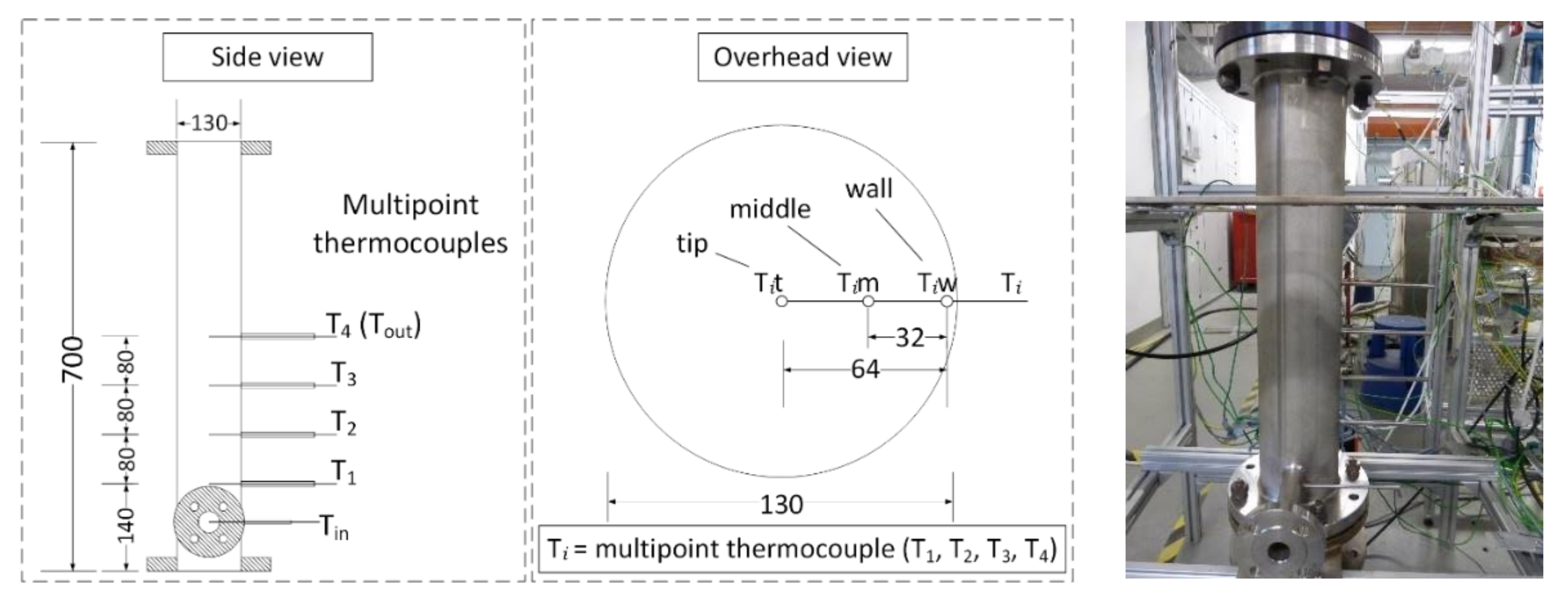
Considering the above-mentioned criteria, a reactor based on a standard steel pipe filled with the granules is designed (Figure 1). A countercurrent flow was chosen where the unreacted material enters from the top of the reactor. The hot air and water vapour enter from the bottom of the reactor and stream through the bulk of granules to the top. The main design parameter is the diameter of the pipe. On the one hand, a large diameter is required to keep the gas stream below the fluidisation velocity. On the other hand, the gas volume flow needs to be large in order to deliver enough thermal power to drive the reaction. In addition, the gas velocity should not be too low in order to ensure a sufficiently high heat transfer coefficient from gas to particle. The selected design therefore seeks to balance these conflicting parameters by finding an operation window that allows high heat transfer coefficient at a gas velocity still below values that fluidise the reaction bed.
The first criterion for the design is the temperature difference between the gas and the reaction equilibrium, which is assumed to range from 50 to 200 K. Based on this, for a nominal power of 1.2 kW (for 200 K temperature difference) a volume flow of 16 Nm3/h is required. Hence, the operational power varies from 0.3 to 1.2 kW for temperature differences between 50 and 200 K, respectively. Based on a chosen nominal flow and a given particle diameter, the minimal fluidisation velocity ( U m f ) can be calculated at the maximum inlet temperature of 550 °C and pressure of 1 bar (see Section 2.5, Equations (1)–(3)). This velocity corresponds to the maximum velocity of the reactor design and must not be exceeded.
In our case the diameter of the reactor was chosen to 0.130 m and consequently a volume flow of 45 Nm3/h corresponds to a gas velocity in the reactor of 0.94 m/s, which is slightly below the minimal fluidisation velocity of 1 m/s. Hence, the maximum thermal power at which the reactor can be operated using this gas velocity and a 50 to 200 K temperature difference varies from 0.9 to 3.5 kW accordingly. In addition, the gas velocity affects the heat transfer coefficient (α) between gas and particles. The calculated values of α result in 140 and 248 W/m2 K for volume flows of 16 (nominal) and 45 (maximum) Nm3/h, respectively (see Section 2.6, Equations (4)–(12)).
The second criterion used is the size of the reaction bed. In the reactor pipe, a 0.24-m-high bed accounts for a 3-L volume of storage material which corresponds to 2.160 kg and an amount of energy of 0.78 kWh. Furthermore, the bed size determines the surface area of the granules available for the heat exchange with the gas. Bearing in mind that the granules have a small diameter of 2 mm, the surface area available for heat transfer amounts to 4.8 m2. This area and the heat transfer coefficient at nominal conditions result in a specific power of 0.67 kW/K and a specific power density of 224 W/K L when the 3-litre storage material is considered. By comparing the specific power of the reactor to the nominal thermal power of the gas flow (0.3–1.2 kW), it is expected that the reactor can be operated with a small temperature difference between the reaction bed and the gas. Hence, the energy of the gas flow will be rapidly absorbed by the particles, the reaction zone will be small and progressively move upwards through the bed of granules. The reaction is therefore expected to be controlled by the gas volume flow and the inlet temperature of the gas. Finally, a homogeneous outlet temperature of the gas close to the equilibrium temperature of the reaction is foreseen to be reached. The design parameters are summarised in Table 1.

2.2. Test Bench

The test bench consists of three main units: the reactor unit, the heat transfer fluid (HTF) supply unit and the reaction gas supply unit (Figure 2).
A feeding tank (20 L) is located at the top of the reactor unit and under it a controlled flap can adjust the mass flow of the granules into the reactor. A double cylinder jacket connects the upper flap and the reactor. The inner cylinder has a fine steel mesh wall (2 µm diameter) that allows the air and steam to leave the reactor and separates the gas from the solid material. The lower section of the reactor (100 mm high) is filled with 10-mm glass beads and then the samples are filled to make a 240-mm-high reaction bed (approximately 3 L). At the end of a reaction cycle the lower flap is opened and the material can flow out of the reactor.
Ambient air is used as heat transfer fluid (HTF) to supply heat to the reaction bed. The air is first compressed and then moisture and CO2 are removed in an adsorption dryer. Once the air is dry and CO2-free, the volumetric flow is set before the fluid is heated up in the electrical heaters. The heated air is then directed to the reactor. In the reaction gas supply unit, an evaporator is used to produce the steam that is later supplied to the reactor by means of a mass flow controller (MFC). A gas analyser is connected to the outlet pipe to monitor the content of water vapour present at the outlet of the reactor.
Four multipoint thermocouples (T1, T2, T3 and T4) are attached to the reactor at 4 different heights and one single thermocouple is attached at the inlet (Tin). Thus, the temperature at 13 different positions can be monitored (see Figure 1, left). Thus, the temperature distribution (axial and radial) throughout the reaction bed and the gas temperature right above it can be monitored.

2.3. Materials

2.3.1. Uncoated Granules

As reference material, commercially available granulated Ca(OH)2 (Sorbacal® H90) was supplied by Rheinkalk GmbH. The product contains 92.9 wt.% Ca(OH)2 and granules with diameter between 1.6 and 2 mm were used in the experiments (Bulk density: 721 kg/m3).

2.3.2. Coated Granules

Granulated Ca(OH)2 (Sorbacal H90) was put into a mixer (Eirich, type R02/E) where water as adhesion promoting agent was added under co-current flow. Subsequently, nanostructured Al2O3 (AluC©, Evonik) was added to the granules up to the point that all surfaces were thoroughly covered, and no fines of the additives aggregated separately within the mixing container. In case of this sample, no further processing of the material was performed. The content of Al2O3 accounts for 10 wt.%. Coated granules with diameter between 1.6 and 2 mm were used in the experiments (Bulk density: 822 kg/m3).

2.4. Experimental Procedure

In two measurement series, batches of 3 L of uncoated and coated granules are filled in the reactor. 10 cycles of dehydration and hydration are carried out with each batch which remained in the reactor for the whole series. Only after the last cycle the lower flap is opened to test the flowability of the storage material. The experimental parameters are given in Table 2.

2.4.1. Dehydration

First, the upper flap is opened and the samples (Ca(OH)2) contained in the feeding tank fill the reactor up until the level right above of the thermocouple T3 (see Figure 2). In order to preheat the storage material in the reactor, the air volume flow is supplied and the preheating temperature (compare T H T F ,   s t a r t in Table 2) is set. Once the temperature is stable, it is increased to the dehydration set temperature ( T H T F ,   s e t in 
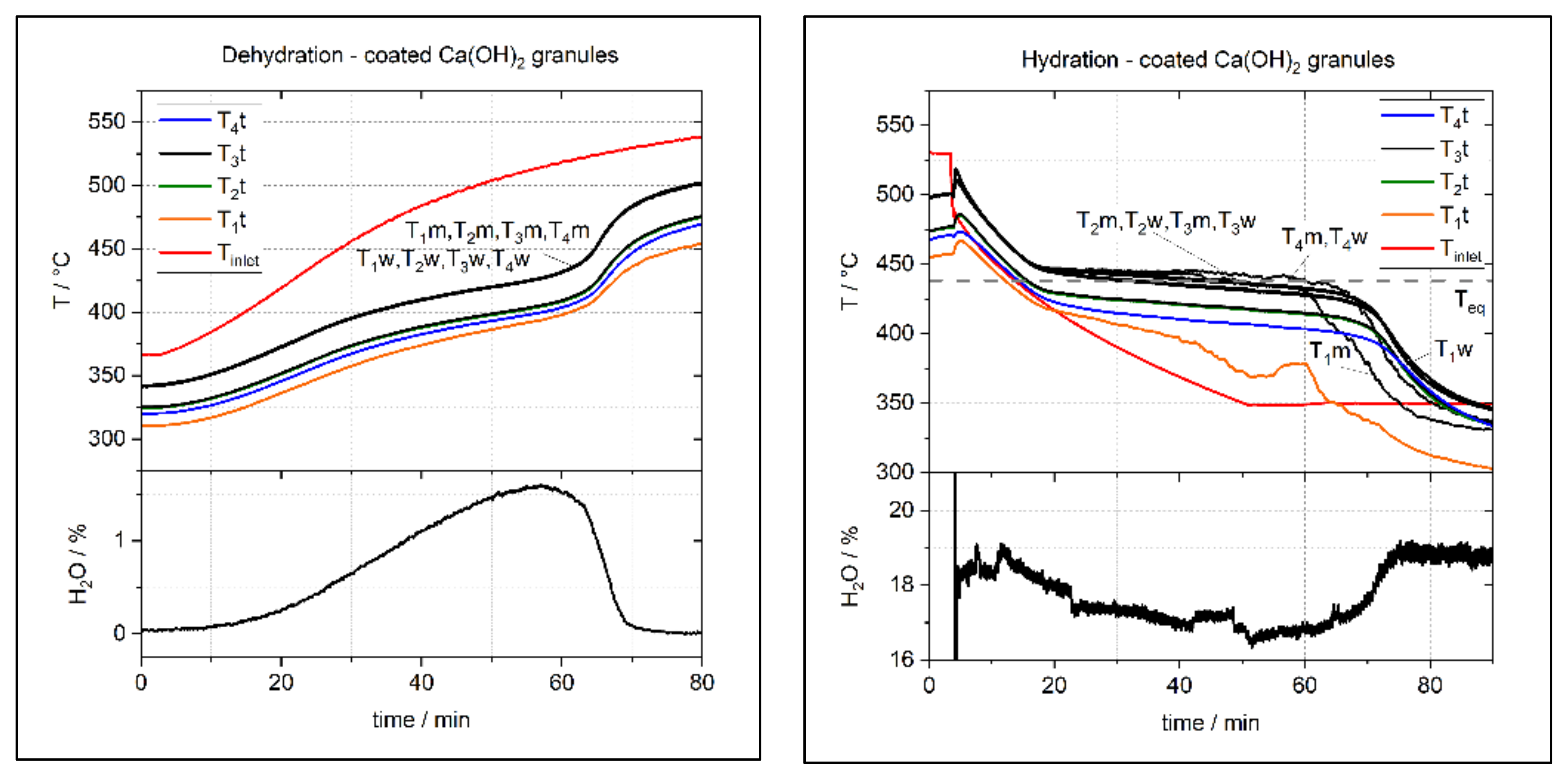
Table 2). The dehydration starts when the storage material temperature exceeds the equilibrium temperature, and an increase of water vapour is detected by the sensor located at the outlet pipe of the reactor. The dehydration is complete when the content of water vapour measured in the gas analyser decreases again and stays constant.

2.4.2. Hydration

The dehydrated samples (CaO) contained in the reactor are preheated with air volume flow at a starting temperature. In the reaction gas unit, water vapour is prepared in the evaporator and the MFC is set. The valve that connects the evaporator and MFC is opened and the water vapour mixes with the air volume flow before they stream into the reactor. At the same time, the temperature of the air flow is decreased to below the equilibrium temperature to start the hydration of the samples. Since the CaO present in the samples reacts with the water vapour supplied, the content of water vapour at the outlet sensor of the reactor decreases. When the value of the water content increases again and stabilises, the hydration is complete.

2.5. Determination of the Minimal Fluidisation Velocity

The minimal fluidisation velocity ( U m f ) is calculated by the following expression [32]:
U m f = R e m f μ ρ d p
where μ is the dynamic viscosity of the gas, ρ is the density of the gas and d p the diameter of the particle. The term R e m f refers to the Reynolds minimal fluidisation and is calculated as follows:
R e m f = 33.3 2 + 0.33 A r 0.5 33.3
where A r corresponds to the Archimedes number and can be determined by the following expression:
A r = g ρ ρ p ρ d p 3 μ 2
ρ p refers to the density of the particle, which accounts for 2313 kg/m3 [24] and g to the gravitational acceleration: 9.81 m/s2.

2.6. Determination of the Heat Transfer Coefficient

The heat transfer coefficient (α) can be represented by Equation (4) [33]:
α = N u λ d p
where λ is the thermal conductivity of the gas and N u corresponds to the Nusselt number, which can be determined based on the factor f a and the Nusselt number for sphere ( N u s p h e r e ), in laminar ( N u l a m ) and in turbulent flow ( N u t u r b ) (Equations (5)–(8)).
N u = f a   N u s p h e r e
N u s p h e r e = 2 + N u l a m 2 + N u t u r b 2  
N u l a m = 0.664   R e ψ   P r   3
N u t u r b = 0.037 R e ψ 0.8   P r 1 2.44   R e ψ 0.1   P r 2 3 1
The factor R e ψ or Reynolds coefficient in the void fraction is calculated by means of the minimal fluidisation velocity ( U m f ), the diameter of the granule ( d p ), the kinematic viscosity of the gas ( v ) and the void fraction of the reactor ( ψ ) (Equation (9)):
R e ψ = U m f   d p ν   ψ
The Prandtl number ( P r ) is the quotient of the kinematic viscosity ( ν ) and thermal diffusivity ( a ) of the gas (Equation (10)):
Pr = ν a
The void fraction ( ψ ) can be obtained from the volume ( V ) of the reactor and the volume of all the granules in the bed ( V F ) (Equation (11)). For the experiments in this work, ψ amounts to 0.625.
ψ = V V F V
The factor f a is calculated as follows:
f a = 1 + 1.5   1 ψ

2.7. Determination of the Partial Pressure of Water Vapour and Equilibrium Temperature

The pressure of water vapour in the gas stream mixture is calculated by Equation (13):
p H 2 O = n ˙ H 2 O n ˙ a i r + n ˙ H 2 O 1.032   b a r
where n ˙ is the molar flow and is determined by Equations (14) and (15):
n ˙ H 2 O = m ˙ H 2 O M H 2 O
n ˙ a i r = m ˙ a i r M a i r
where m ˙ is the mass flow and M the molar mass. Both mass flows (water vapour and air) are measured by mass flow controllers (MFC) in the set up (compare Figure 2). The equilibrium temperature used for analysis in this work is determined by the equation of Samms and Evans [34]:
ln p H 2 O b a r = 11375 T   K + 14.574

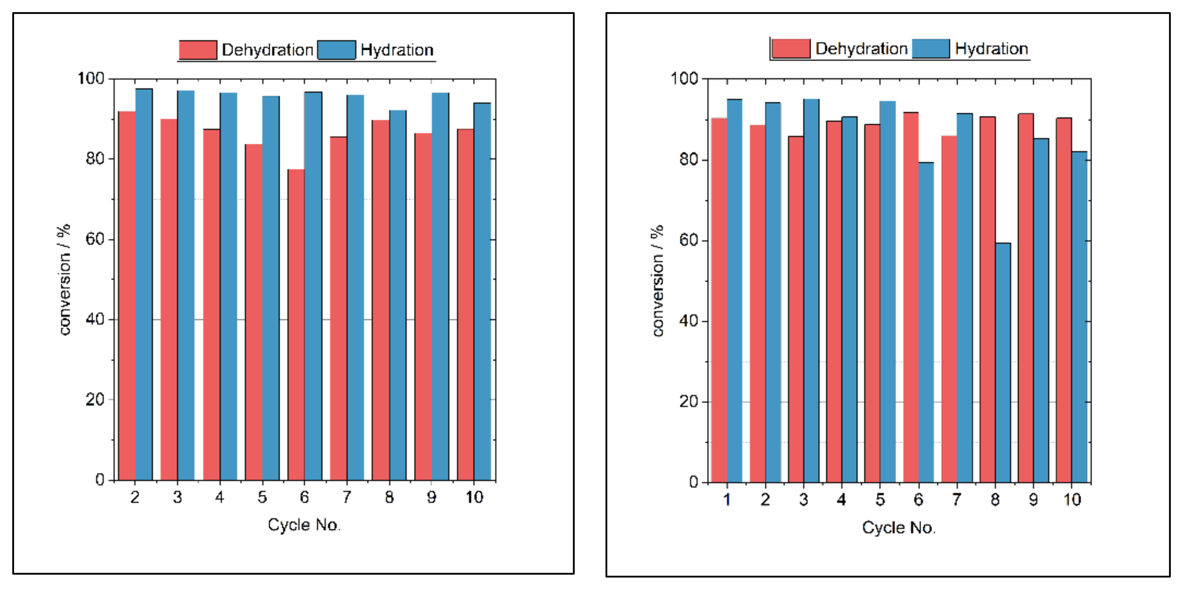
2.8. Cycling Stability

To determine the degree of conversion, after each experiment a sample of the storage material is taken and subject of thermogravimetric analysis (TGA). A simultaneous thermal analyser (Netzsch STA 449 F3 Jupiter) was used to carry out these measurements. In this device, the atmosphere inside the furnace is maintained inert by using volume flows of nitrogen as protective and purge gases. The sample was heated up to 850 °C and the experiments lasted 2 h. The extent of dehydration and rehydration in the test bench X d h y and X h y , respectively, is calculated by Equations (17) and (18):
X d h y % = 1 m H 2 O m e a s u r e d m H 2 O   s t o i c h   100   %
X h y % = m H 2 O m e a s u r e d m H 2 O   s t o i c h   100   %
where m H 2 O m e a s u r e d is the total mass of water dehydrated during the thermal analysis and m H 2 O   s t o i c h is the stochiometric mass of water of the reactive material present in the sample.

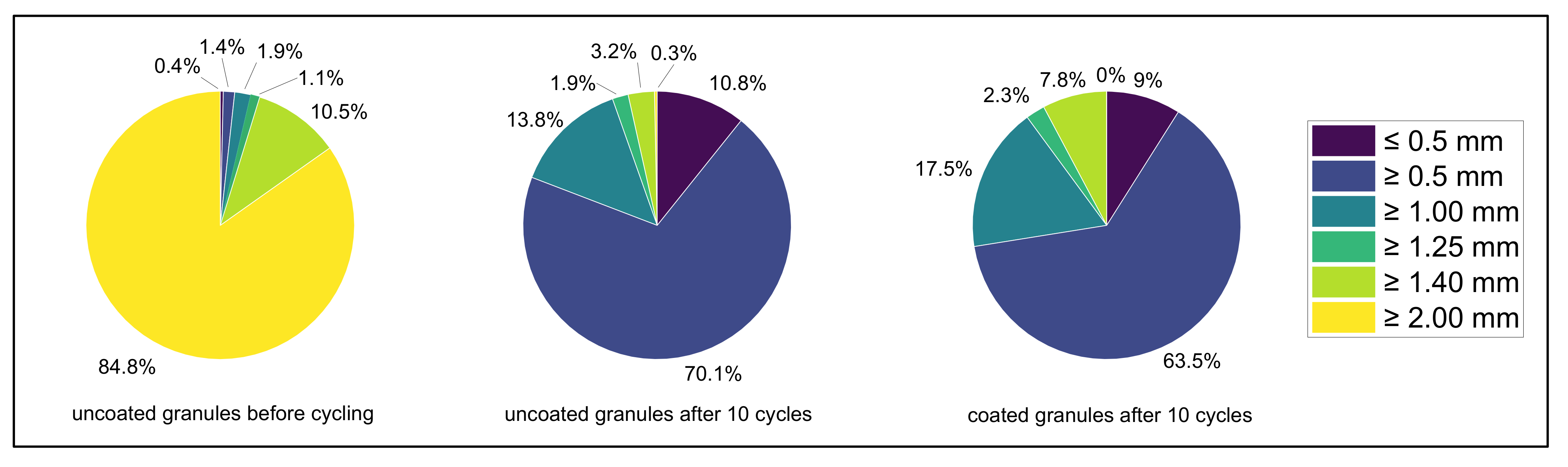
2.9. Structural Integrity

Initially, a defined range of diameters of the uncoated granules was selected as reference material and as raw material for the encapsulation process of the coated granules before it undergoes thermochemical cycling. This diameter range between 1.4 and 2 mm was prepared by sieving the initial granules with broader diameter distribution. After tenfold thermochemical cycling, the particle size distribution of the uncoated and coated material was tested by sieve analysis again. Therefore, sieves with the mesh sizes of ≥0.5 mm, ≥1 mm, ≥1.25 mm, ≥1.4 mm and ≥2 mm were used. The sieving duration, associated with a vibrant motion of the stacked sieves was each 5 min.
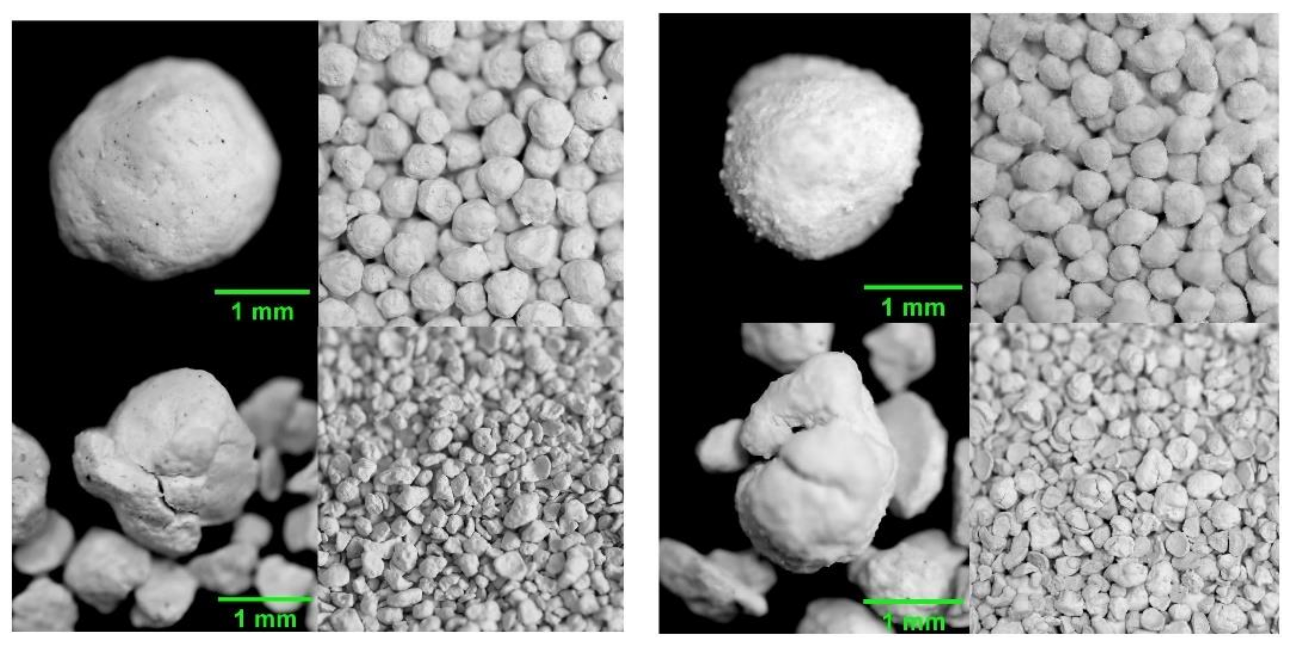
Additionally, images of granules taken after every experiment are used in order to qualitatively assess the degree of deterioration over the experimental series.

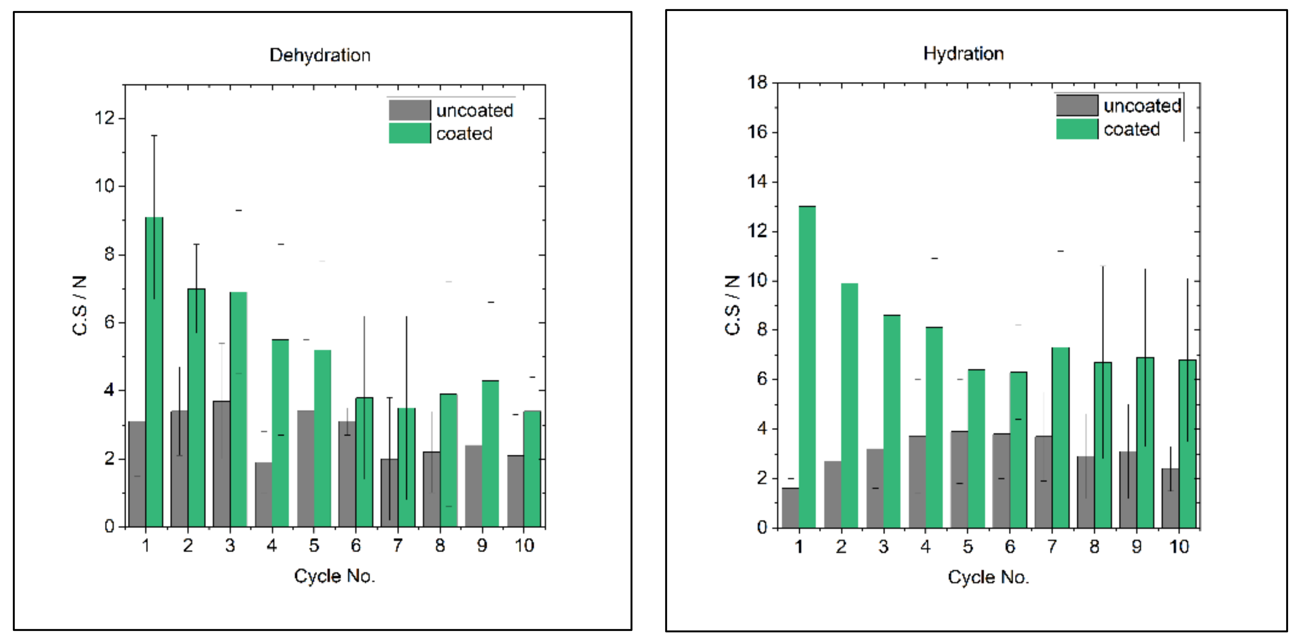
2.10. Mechanical Stability

The mechanical stability of the uncoated and coated granules was tested before and after tenfold thermochemical cycling by dynamometry. Therefore, a manually operated test stand equipped with a force gauge (SHIMPO, FGE-100X, max. capacity: 500 N, resolution 0.1 N) was used. All measurements were conducted with a flat-head measuring module mounted to the force gauge with the sample lying on a flat steel plate. For each sample, an amount of 25 individual granules were measured. The final mechanical stability of each sample was calculated as the mean value of the individual measurements whereas the respective standard deviation gives the uncertainty of stability. This uncertainty is thereby not only interpreted as statistic deviation from the mean, but also gives an idea about the variation of inhomogeneities within the sample’s microstructure affecting the mechanical stability.

2.11. Flowability

After the last hydration of the series, the ability of the reaction bed to move through the reactor is tested. The lower pneumatic flap is opened to let the glass beads and the bulk of granules leave the reactor by the action of gravity.

2.12. Morphological Investigation and Determination of Phase Composition

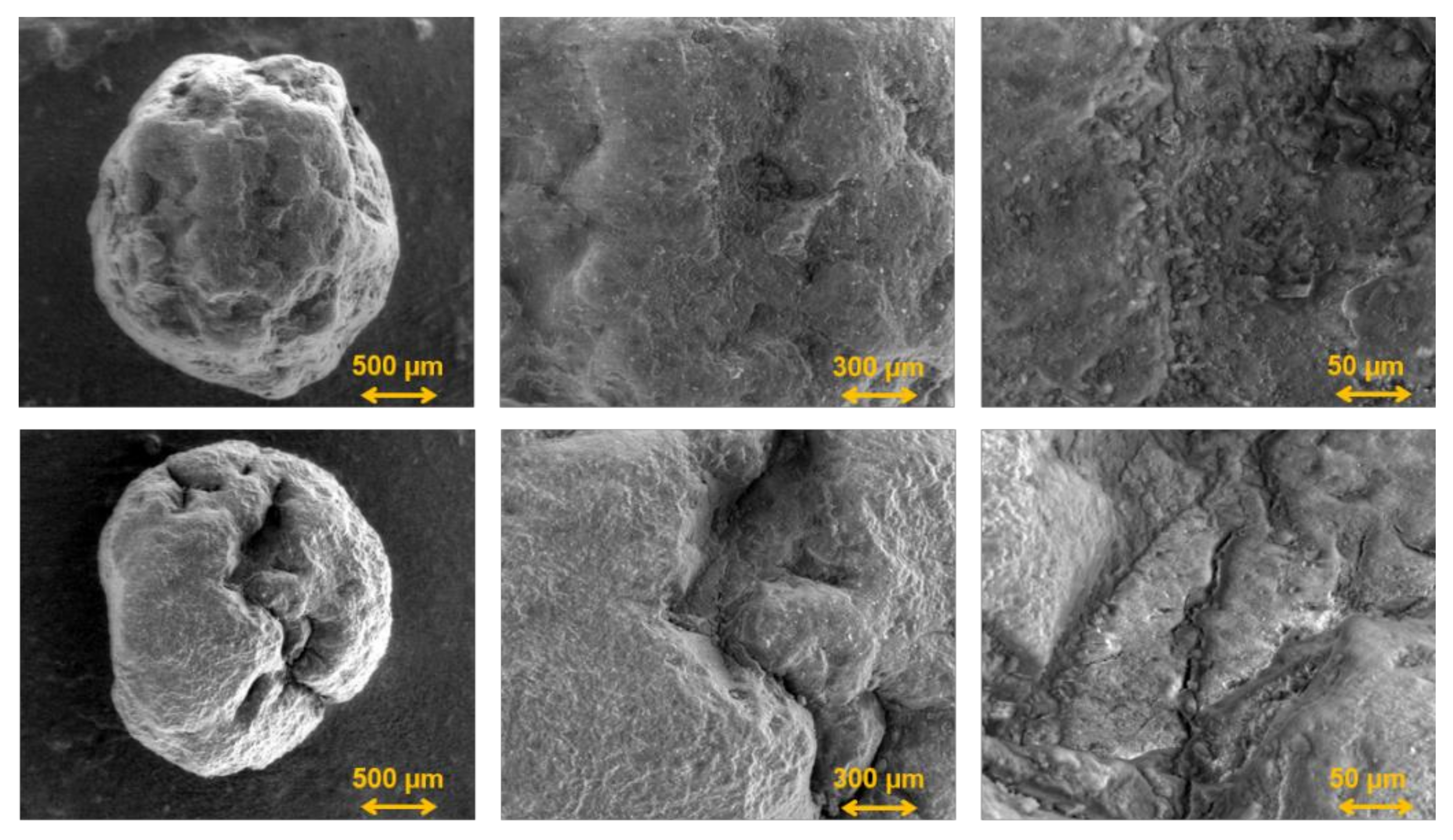
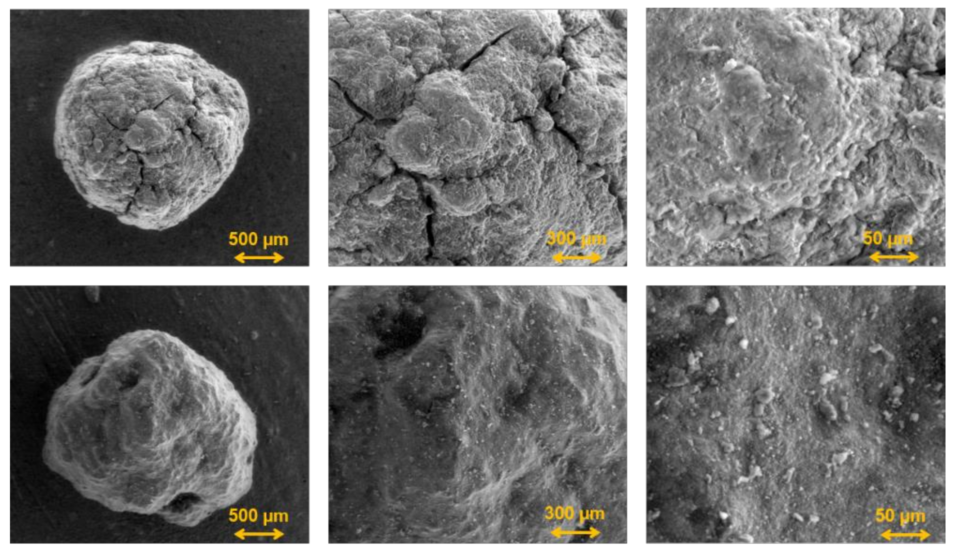
The morphology and the surface texture of the samples were examined by scanning electron microscopy (FEI Quanta FEG 250). Thereby, the initial granules are compared to the granules after tenfold thermochemical cycling. All micrographs were taken in low vacuum mode at a pressure of 90—110 Pa using a large field detector for secondary electron imaging. The high resolution of the detector allows for a high-resolution imaging as needed for this purpose.
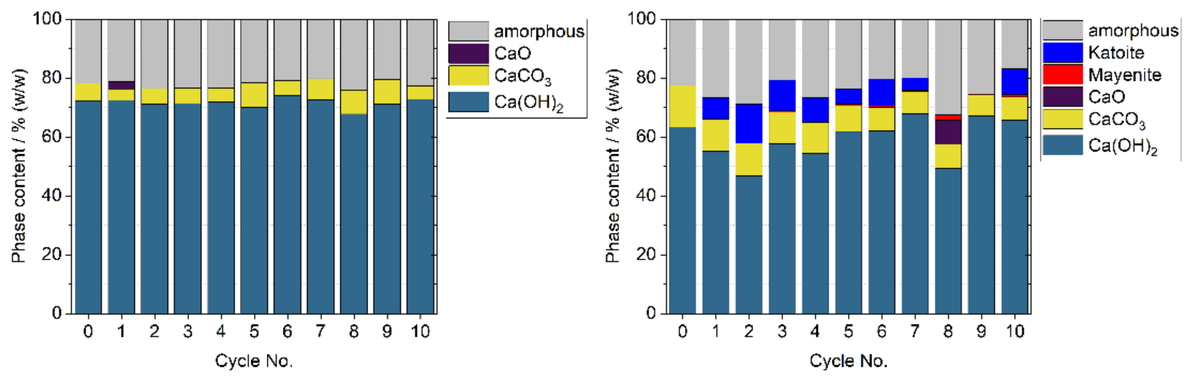
The crystalline phase composition of the materials was probed by X-ray powder diffraction (Panalytical X’Pert Pro PW 3040/60) in a scan range between 8° to 70° 2θ using Cu Kα-radiation. For phase quantification by Riteveld-refinement of the obtained pattern, ZnO (NIST standard reference) was used as external standard.

3. Results and Discussion

3.1. Reactor Operation

3.1.1. Thermal Cycling with Uncoated Granules

2.160 kg of the uncoated granules were subject of a 10-fold thermochemical cycling. The results are used as a baseline to analyse the reactor performance and operational behaviour according to the design considerations.
Figure 3 (left) shows a reference dehydration experiment with the uncoated samples. First, the air inlet temperature (Tin) is set at 350 °C and the volumetric flow at 45 Nm3/h. Once the temperature is stable, the experiment starts by increasing the gas inlet temperature to 550 °C. The dehydration starts approximately at minute 25 when the rising slope of all the bulk temperatures start to decrease indicating that the endothermal reaction is occurring. At the same time, the measured water vapour content at the outlet starts to increase, confirming that dehydration takes place. After minute 68, the bulk temperatures increase faster again and the vapour content falls, indicating that a major part of the storage material is already dehydrated. The dehydration of the material proceeds until approximately minute 100, when the temperatures in the bulk reach their maximum and the content of water vapour returns to its initial values. At this point the dehydration procedure is considered finished.
Bearing in mind that water vapour is not supplied during the charging process, the equilibrium temperature is actually below the air inlet temperature (350 °C) during the pre-heating stage. Therefore, it is likely that a portion of the bulk starts dehydrating but at a very slow rate. However, no significant release of water vapour is measured at this point. Therefore, even though dehydration might occur, it is not of technical relevance. As the experiment proceeds, the temperature of the storage material increases. Consequently, the reaction kinetics becomes faster and the rate at which water vapour is released rises as well. In general, a plateau in the temperatures of the bed appears when the heat influx is in equilibrium with the thermal energy absorbed to drive the endothermal reaction. Since the plateau observed is not completely flat, in our chosen operation mode the heat influx to the reaction bed is always higher than the energy taken up by the reaction.
The hydration shown in Figure 3 (right) follows subsequently after the dehydration. The air inlet temperature initially remains at 550 °C at a lower volumetric flow rate of 16 Nm3/h. After initially reaching steady temperatures in the bulk, the gas inlet temperature is lowered to 350 °C and water vapour is additionally supplied to the gas stream at a 4 kg/h mass flow. The mixture of 16 Nm3/h of air and 4 kg/h water vapour at a total pressure of 1 bar at the reactor inlet corresponds to a water vapour partial pressure of 0.24 bar (see Section 2.7). At around minute 20, the slope of the falling temperatures within the bulk significantly decreases, indicating that the exothermal reaction accelerates. The temperature at which this effect starts, approximately 440 °C, corresponds to the calculated equilibrium temperature given by the partial pressure of water vapour present in the reactor (compare dotted line in Figure 3, right). Accordingly, the content of water vapour measured at the reactor outlet falls. At minute 80, the temperatures start to decrease again, which indicates that the heat release becomes smaller. This is again in accordance with the increase of water vapour measured. The reaction is complete at minute 100 when the bulk temperatures are below the inlet temperature because no more heat is released from the granules.
During the discharge, the heat release produced by the exothermal reaction leads to temperatures with a distinct plateau and with a slow but constant decrease in all measuring points, which lasts approximately 60 min (minute 20–minute 80). The bulk and outlet temperatures measured near the wall (Tw) and in the middle of the thermocouples show a plateau at 430 °C. Furthermore, a fairly constant difference to the gas inlet (350 °C) is observed between the minute 45 and 80. In the same region of the reactor, close to the wall (compare Tw and Tm), the measured temperatures of the bulk and the gas above it are the same, which indicates an excellent gas to particle heat transfer coefficient. It is observed, however, that the temperatures measured in the middle of the reactor (Tt) are 15–25 K lower.

3.1.2. Thermal Cycling with Coated Granules

In a second measurement series a 3.025-kg batch of coated granules was cycled 10 times in order to investigate the performance of the reactor concept with coated granules. The aim was also to cycle the novel granules under technical-scale reactor conditions. Samples of the granules were taken after each experiment and characterised in terms of cycling stability, structural integrity, mechanical stability and flowability. Morphological investigation is carried out by scanning electron microscopy after the 10 cycles. The results related to the characterisation of the properties of the granules are presented in Section 3.3.
Figure 4 (left) displays one dehydration experiment with coated granules. The storage material in the reactor is preheated to 350 °C and a volumetric air flow of 45 Nm3/h. The experiment then starts by increasing the gas inlet temperature to 550 °C. At around minute 20, the rising slope of the temperatures in the reaction bed start decreasing and the water vapour content measured at the outlet of the reactor increases. This indicates that the dehydration of Ca(OH)2 occurs in the reactor. Shortly after minute 60, the bulk temperatures increase faster again, and the vapour content falls. After 70 min, the vapour content reaches its initial value again which clearly indicates that the reaction is completed.
For the subsequent hydration procedure, presented in Figure 4 (right), the air volumetric flow is lowered to 16 Nm3/h and the gas inlet temperature remains initially at 550 °C. After having constant temperatures in the bulk at the beginning, the procedure is started by lowering the gas inlet temperature from 530 °C to 350 °C. At the same time, water vapour is added to the gas stream at a mass flow rate of 4 kg/h. The conditions result again in a vapour partial pressure of 0.24 bar (see Section 2.7). At minute 20, the slope of the temperatures within the bulk changes and stay fairly stable at around 440 °C, which is in accordance with the calculated equilibrium temperature based on the partial pressure of water in the reactor (compare dotted line in Figure 4, right). The gas analyser, accordingly, detects the decrease of the water vapour content at the outlet. Both the temperature plateau and the measured water vapour content confirm that the release of heat and the uptake of H2O in the CaO of the samples occurs. After the minute 90, the bulk temperatures are below the air inlet and the reaction is therefore complete. A reference hydration experiment is shown in Figure 4 (right).

3.2. Thermodynamic Analysis of the Reactor Concept

3.2.1. Thermal Power and Energy Release

Figure 5 (left) displays the power and energy curve for dehydration of uncoated granules. Here, the maximum difference between the endothermal reaction temperature plateau and the gas inlet temperature allowing for the calculation of the maximum power required during dehydration. This value accounts for −1.76 kW and lies within the design considerations (compare Section 2: reactor design). The outlet temperature of the gas is equal to the temperatures in the bulk (see Figure 3, left) which indicates that the entire thermal capacity of the gas volume flow is used. This supports the hypothesis that due to the high heat transfer between gas and particle a small reaction zone is formed which moves through the bulk up to the top as the experiment proceeds. Furthermore, the process is controlled by the thermal capacity of the gas flow. Thus, a larger difference between gas and dehydration temperature could increase the thermal power. Alternatively, higher gas volume flows are capable of having the same effect. However, this would lead to undesired fluidisation of the bed in the current design. In terms of energy efficiency, the energy input is significantly larger than the energy required to dehydrate the mass of the reactive material due to the large amount of sensible heat necessary to heat up the reactor and thermal losses that cannot be avoided. The effect of the latter is visible in the last part of the energy curve which never reaches a steady value. Instead, it always displays a rising slope and accounts for −6510 kJ at the end of the experiment. Nevertheless, for a continuous system as the one proposed in this work such sensible heat losses are only relevant for the preheating phase of the first cycle.
For hydration, the maximum difference between the minimal gas inlet temperature and the equilibrium temperature of the exothermal reaction determines the maximum power obtained of 0.62 kW (see Figure 5, right) and is in the range foreseen in the reactor design (compare Section 2). Similar to dehydration, the temperatures measured in the bed and at the outlet are the same which is proof of very high heat transfer between gas and particle. This also leads to a small reaction zone within the bed that moves up through it. The hydration process can also be controlled by the thermal capacity of the gas flow. Thus, the power could be increased either by setting a lower gas inlet temperature or by adjusting a higher equilibrium temperature. The thermal energy released accounts for 2392 kJ at minute 90 and remains fairly stable until the end of the experiment. This is different from the dehydration experiments due to the higher thermal losses.
To sum up, a successful operation of direct gas flow through a bed of granules was achieved. The design of the novel reactor concept presents a conflict in the use of high volume flows due to the undesired fluidisation of the bed of granules. Therefore, the main requirement for the maximum gas flow to reach high thermal power is that it remains below the minimal fluidisation velocity. Such volume flow and the difference between the gas inlet temperature and the endothermal/exothermal reaction equilibrium temperature defines the operational power. Finally, although the operation at higher pressures in principle allows for lower gas volume flows, it increases the complexity in the reactor design.

3.2.2. Gas Distribution within the Reaction Bed

Figure 6 depicts the temperature distribution for the dehydration of uncoated granules at minute 60. The data of the thermocouples located at the wall (Tw) and middle (Tm) in all the levels (T1–T4) shows a homogeneous axial distribution of the temperature. Conversely, in the center of the reactor the temperatures are approximately 25 K lower (compare Figure 1, left). Since this is observed in the dehydration and hydration experiments and for both materials, it is clear that the material has no influence on the gas distribution through the bulk. Instead, it is likely that the position of the inlet pipe in the reactor produces an uneven distribution of gas. To address this issue, a gas nozzle should be considered in the reactor designs.

3.3. Material Performance Analysis

After each thermal cycle, performed as described in the procedure section, a sample of granules was taken out of the reactor. The samples were characterized in several post analysis in order to assess the performance of the coating of the granules compared to uncoated granules. Cycling stability, structural integrity, mechanical stability, phase composition, morphology and flowability were analysed over the samples applying the respective methods explained in Section 2.

3.3.1. Cycling Stability

Figure 7 depicts the conversion achieved after every experiment carried out with uncoated and coated granules. As stated in Table 2, the values of the first cycle using uncoated granules correspond to the setting into operation experiments. Therefore, the data of dehydration and hydration in this cycle are not used for analysis. From cycle 2, the values found for rehydration of the uncoated granules are stable along the cycles and ranged between 92% and 97.5%. On the other hand, the dehydration varied from 77.5% to 92%. In general, the extent of dehydration was found lower than the following hydration in every cycle. This could be explained by the sampling method used which involves withdrawing a small amount of material and placing it in small jars for later TG analysis. Thus, the dehydrated samples probably rehydrated partially during the exposure to ambient air during the sampling and storage. Furthermore, since there is no clear degradation trend observable, these variations can be dedicated to the post processing of the small samples. In particular the conversion after dehydration in cycle 10 reaches almost 90% which can be assumed as technically full conversion. Additionally, the hydration conversion values are very stable over cycling, clearly indicating that previous dehydrations where also completed in the reactor.
Regarding the coated granules, it is observed that the dehydration reaches values similar to the reference uncoated material (around 90%). In addition, the conversion remains stable during the entire experimental series. On the other hand, the rehydration is stable until the 5th cycle with values that reach over 90%. After this, an oscillating behavior is observed with the lowest value in the 8th cycle (60%) and significantly higher values (over 80%) in the last two cycles of the series. This finding could suggest that the reactivity of the coated granules is affected with the cycles due to a change in the composition. In order to further understand this, a more detailed analysis of the composition of the coated granules is described later in this work (see Section 3.3.4).

3.3.2. Structural Integrity

Figure 8 displays the state of the granules before and after the 10-fold cycling. Before the granules are cycled, they are compact, present a smooth surface and have a fairly homogeneous size distribution (see Figure 8, top left and top right). However, after 10 cycles, the signs of deterioration are clear since the granules display visible cracks or broke into smaller pieces (see Figure 8, bottom left and bottom right). Sieve analysis was carried out over the whole cycled batches and the results show that for both materials the largest share of the granules corresponds to broken pieces with a diameter between 0.5 and 1 mm (Figure 9). This finding leads to the question whether the broken pieces would further break with additional cycling, or a stable diameter size range has been achieved.
In order to estimate the amount of fines generated during sieving, at first the granule diameter distribution of the selected particle size fraction of uncoated granules was determined. Thereby it was found that after sieving 95.3% of the granules are in the intended diameter range between 2 mm and 1.4 mm, while a fraction of 4.7% is of smaller diameter after the sieving due to abrasion occurring to the granules during the process. With this as a reference for the evaluation of the cycled samples, it was found that the uncoated and coated granules, undergo a significant deterioration during cycling. However, by coating the Ca(OH)2 storage material with nanostructured Al2O3, the size fraction with diameters between 1 mm to 1.4 mm make a total fraction of around 28% while for the uncoated material only around 19% fall into this range. In addition, the amount of particles with diameters smaller than 1 mm is significantly reduced for the coated granules (Figure 9) This evidences the positive effect of the coating over the structure of the granules. Considering the fact that besides deterioration due to volumetric expansion and contraction, the intact granules decrease in mechanical stability during thermochemical cycling, the results indicate that the coated sample also has a higher resistance to abrasion forces occurring in the bulk during sieving.

3.3.3. Mechanical Stability

The mechanical stability of the uncoated granules as well as of the coated with nanostructured Al2O3 was examined after each of the ten dehydration and hydration reactions in the reactor. From the results, it can be shown that there is a strong discrepancy in the mechanical stability of the respective dehydrated and hydrated species. With regard to the uncoated storage material, it can be seen that the initial stability is of approximately 3 N and then it increases slightly in the next two cycles for the dehydrated species. A similar effect is observed for the hydrated form but with lower values of crushing strength. In fact, in the course of thermochemical cycling, the stability of the hydrated species slightly increases up to the fifth cycle. Furthermore, for both dehydrated and rehydrated uncoated granules, the mechanical stability decreases after the fifth cycle. In contrast, after the first dehydration the mechanical stability of the coated granules is three times higher than for the uncoated material and this difference increases even further after the first hydration. The mechanical stability of the coated granules also decreases in the course of thermochemical cycling by roughly 50% after ten completed de- and rehydration reactions. Nevertheless, it is significantly higher than for the uncoated granules (about three times) (Figure 10).

3.3.4. Morphology and Phase Composition

In order to gain a detailed insight and further understanding in the observed particle size distribution and mechanical stability observed, the morphology and texture of the cycled samples were examined in comparison to the respective raw materials by scanning electron microscopy (SEM).
From the micrographs taken on the uncoated Ca(OH)2 granules before and after ten reaction cycles, it can be seen from Figure 11 (top) that initially the granule surface appears rather smooth with some irregularities on the surface which might stem from the synthesis procedure, which is a built-up granulation process. For the examination after tenfold cycling, a visually intact granule was selected. The micrographs taken on this sample reveal numerous cracks on the granules surface throughout the entire surface (see Figure 11, bottom).
In contrast, the surface of the coated starting material reveals several cracks and is covered by a material rather rough in appearance, which is the nanostructured Al2O3 covering the entire granule (see Figure 12, top). After tenfold thermochemical cycles, no cracks on the granules surface are visible and the texture now appears to be rather smooth and dense, containing some larger pores as necessary for the transport of the gaseous reaction partner during charging and discharging (see Figure 12, bottom). This observation shows that the nanostructured additive forms a stabilising shell which enhances the structural integrity and mechanical stability of the granules during thermochemical cycling.
It is reasonable that the observed increased structural integrity and mechanical stability of the granulated Ca(OH)2 coated with nanostructured Al2O3 is due to the formation of a stabilising shell during thermochemical cycling. The SEM-micrographs already revealed that there is a significant change in the texture of the respective sample before and after cycling. However, to explain the stabilising effect, it is necessary to learn about the phase composition of the shell during the course of thermochemical cycling. Therefore, the phase composition of the shell material was examined on the hydrated species by X-ray diffraction and quantified by subsequent Rietveld-analysis performed on the obtained patterns and compared to the initial phase composition of the uncycled uncoated granules as well as to the phase composition of the uncoated material during thermochemical cycling as reference.
As can be seen from Figure 13 (left) the uncycled uncoated granules contain around 71% of crystalline Ca(OH)2, 7% of CaCO3 which most probable stems from the carbonation of the storage material during its contact with the ambient atmosphere and 22% of X-ray amorphous material. Due to the synthesis procedure of the Ca(OH)2 by precipitation from solution, it is probable that the amorphous material predominantly contains nanoscaled Ca(OH)2. The Ca(OH)2 content of the bulk sample does not significantly change during thermochemical cycling. Except for the first hydration, where a small amount of CaO is detected. This observation can be explained by incomplete conversion after the completion of the previous dehydration reaction. A different situation is found for the granules coated with nanostructured Al2O3. In this case, the composition of the raw material is comparable to the uncoated material but from the first hydration reaction on, new phases can be identified. These phases are Katoite and Mayenite with the chemical composition Ca3Al2(OH)12 and Ca12Al14O33, respectively. The content of these phases varies during thermochemical cycling around a value of roughly 10%(w/w), with a predominant content of Katoite (Figure 13, right). It can be concluded, that these phases are formed as reaction products between the Ca(OH)2 storage material and he nanostructured Al2O3 during the hydrothermal conditions associated with thermochemical cycling and that these phases are responsible for the observed enhanced mechanical stability by creating a largely contiguous structure on the granules surface. Interestingly, the Ca(OH)2 content in this sample of coated granules varies to a larger extend during the individual hydration reactions than in the uncoated granules and the CaCO3 content is slightly higher. It is conceivable, that these fluctuations are caused by the reaction between the stabilising shell and the storage material core. However, according to the results, the content of crystalline storage material Ca(OH)2 after the final tenth dehydration is still in the same range of around 70% as in the starting (uncoated) material. Therefore, the results indicate that there is no major reduction in storage density due to coating by the nanostructured additive.
In summary, from the examination of the morphology and texture of the Ca(OH)2 granules coated with nanostructured Al2O3, it has been found that upon thermochemical cycling the additive forms a largely contiguous layer covering the surface of the granules. By comparative evaluation with the determined phase composition, this layer was found to consist of calcium-aluminate compounds, namely Katoite and Mayenite, which provide the enhanced mechanical stability and increased structural integrity of this material. Thereby, the stabilising effect caused by the formation of these compounds is initiated upon the first hydration reaction of the material, indicating that no further treatment may be necessary in order to achieve the desired effect.

3.3.5. Flowability of the Bed of Granules

The moving bed feature of the reactor was tested after the last experiment with both materials. After cooling down the reactor, the lower flap was opened, and the entire reaction bed flowed out and was collected in a tray.

4. Conclusions and Outlook

This work presents a directly heated moving bed reactor, based on a new concept developed for Ca(OH)2 granules as storage material. Two batches were used: Ca(OH)2 granules and Ca(OH)2 granules coated with Al2O3 nanostructured particles. The thermodynamic performance of the reactor was analysed based on the operation data obtained and reflected against our design considerations. Ten thermochemical cycles (dehydration and hydration) were carried out to analyse the cycling stability, structural integrity, mechanical stability and flowability of the storage granules.
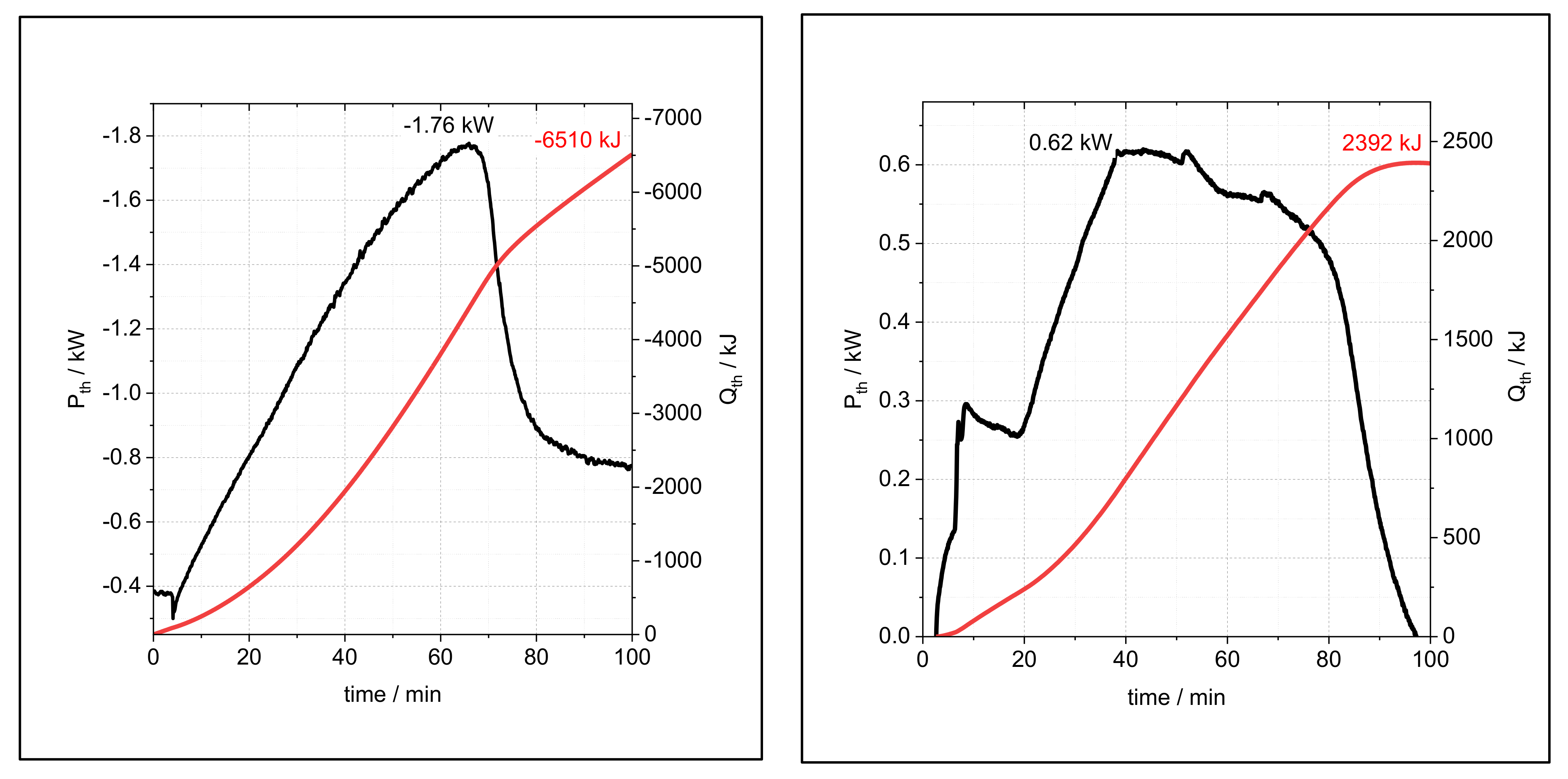
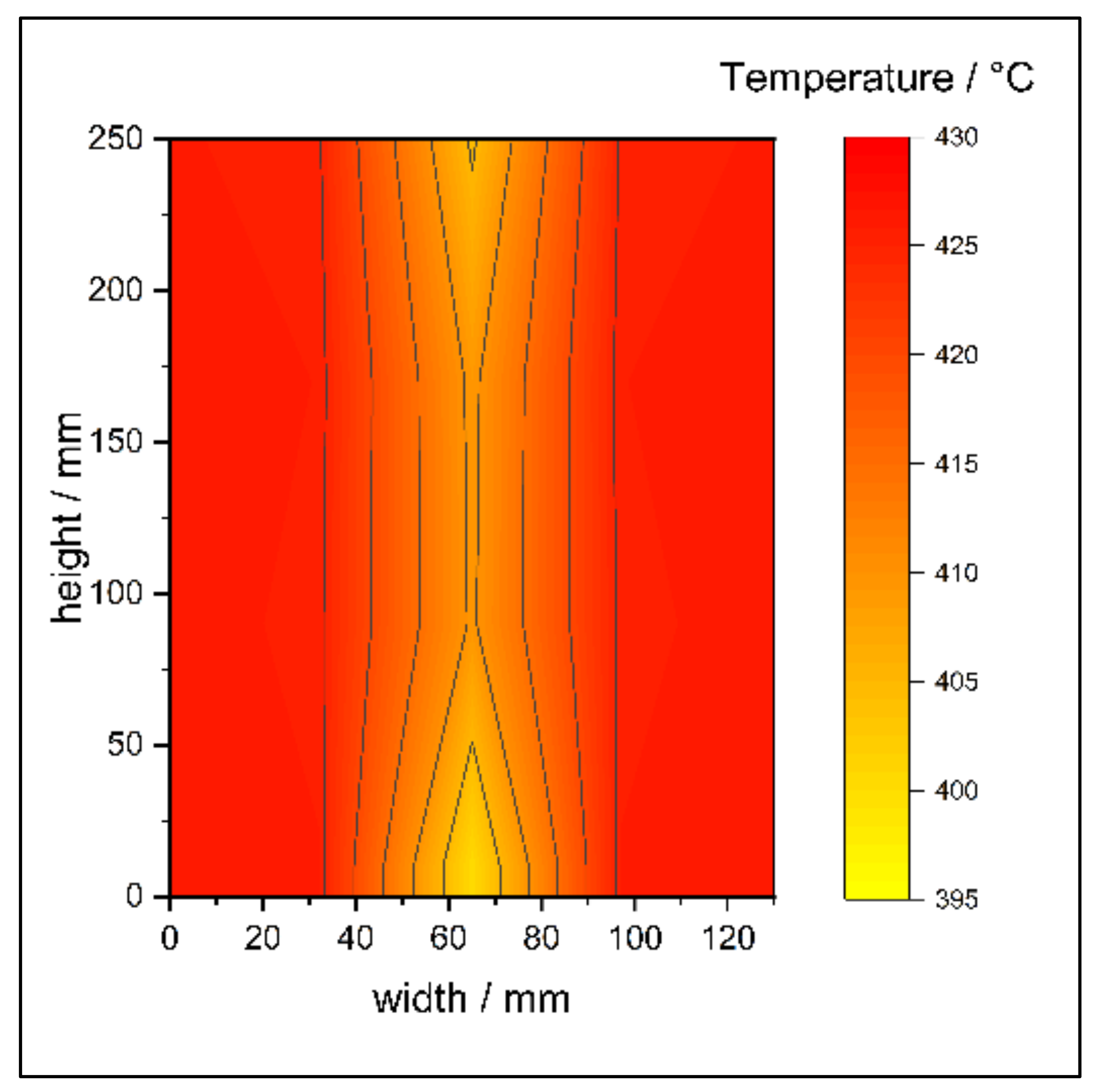
The results obtained demonstrate that the reactor concept is operational. Overall, complete hydration and dehydration of the storage material was demonstrated. The operational data presented shows that the heat transfer between gas and particles was sufficiently high. The experimental data proves that all thermal energy contained in the gas flow was transferred to the particles during reaction. In both operation modes for dehydration and hydration, the process was controlled by the obtained temperature difference and the adjusted gas volume flow. The reaction zone in the bulk therefore had a small length and wanders as the reaction proceeds, from the bottom to the top of the bulk. The maximum thermal power obtained during the dehydration process at the maximal applied gas volume flow accounted for −1.76 kW. The operation of the reactor is capable of achieving even higher power densities. However, this potential is limited by the gas velocity in the reactor which must be maintained below the fluidisation velocity. If the fluidisation can be avoided, the high heat transfer coefficient and the large available surface of the 2 mm granules would enable to reach a specific power density of 300 W/K L.
One important conclusion dedicated to the reactor concept is that the particles freely flowed out of the reactor after 10 cycles. This observation leads to the conclusion that the hot gas stream in direct contact with the granules helps to prevent the agglomeration. Therefore, based on this concept, the gravity assisted movement of cycled particles in technical scale has been demonstrated for the first time [17,27].
With regard to the materials used, it was found that complete technical conversion was achieved. In addition, no degradation attributed to the directly heated reactor concept was observed. After the experimental series, the largest share of both materials broke into smaller pieces which range in the size of 0.5–1 mm. Nevertheless, for the coated granules new phases formed as reaction products between the Ca(OH)2 and nanostructured Al2O3. This resulted in a continuous structure on the granules surface that enhances their mechanical stability without significantly reducing the storage density.
The results obtained in this work show that this reactor concept is very promising and can be considered for the development of a pilot scale reactor with a more efficient heat and gas distribution. Furthermore, different operation settings in which high power densities are achieved by means of higher volume flows but below the fluidisation velocity should be investigated. In order to prevent the reaction bed from fluidising some procedures need to be verified, for example using mechanical barriers or filling the reactor volume completely. In addition, the realisation of the continuous movement of the granules that enables continuous power output should be tested. In parallel, further studies are necessary to better understand the changes occurring in the structure of the granules during the charge and discharge process. Thus, it will be possible to determine when and to what extent the integrity of the granules is lost and if the resulting fragments stabilise in a size range after a larger number of cycles. Moreover, it is necessary to confirm the fluidisation of the bed in practice and analyse the degree of deterioration of the granules in non-fluidising conditions.

Author Contributions

A.C.M.: Conceptualization, methodology, formal analysis, investigation, visualization, writing—original draft. S.A. (Material performance and Morphology and phase composition): methodology, formal analysis, investigation, visualization, writing—original draft; M.L.: conceptualization, methodology, writing—review and editing; M.S.: conceptualization, methodology, investigation (experiments), writing—review and editing, supervision. All authors have read and agreed to the published version of the manuscript.

Funding

This work was partially funded by the European Funds for Regional Development (EFRE Program)—Project-ID EFRE-0801821 and the Deutsche Forschungsgemeinschaft (DFG, German Research Foundation)—Project-ID 279064222—in the frame of the SFB 1244.

Institutional Review Board Statement

Not applicable.

Informed Consent Statement

Not applicable.

Data Availability Statement

Datasets generated during the current study are available from corresponding author on reasonable request.

Acknowledgments

The authors thank Andreas Weigl for his technical support in the preparation of the test bench.

Conflicts of Interest

The authors declare no conflict of interest.

Nomenclature

SymbolDescriptionUnit
m MassKg
d Diameterm
p Pressurebar
T TemperatureK
V VolumeL
g Gravitym2/s
ρ Densitykg/m3
P PowerW
Q EnergyJ
ΔHReaction enthalpyJ/mol
M Molar masskg
n ˙ Molar flowmol/h
V ˙ Volumetric flowm3/h
m ˙ Mass flowkg/h
X Conversion-
αHeat transfer coefficientW/m2 K
HTFHeat transfer fluid-
U m f Minimal fluidisation velocitym/s
MFCMass flow controller-
μ Dynamic viscosity Pa.s
ν Kinematic viscositym2/s
a Thermal diffusivitym2/s
ψ Void fraction of the reactor-
R e m f Reynolds minimal fluidisation-
R e ψ Reynolds coefficient in the void fraction-
N u Nusselt number-
P r Prandtl number-
A r Archimedes number-
C.SCrushing strengthN
CSPConcentrated Solar Power-

References

  1. Farulla, G.A.; Cellura, M.; Guarino, F.; Ferraro, M. A Review of Thermochemical Energy Storage Systems for Power Grid Support. Appl. Sci. 2020, 10, 3142. [Google Scholar] [CrossRef]
  2. Kato, Y.; Sasaki, Y.; Yoshizawa, Y. Thermal Performance Measurement of a Packed Bed Reactor of a Magnesium Oxide/Water Chemical Heat Pump. J. Chem. Eng. Jpn. 2003, 36, 833–839. [Google Scholar] [CrossRef]
  3. Rosemary, J.K.; Bauerle, G.L.; Springer, T.H. Solar Energy Storage Using Reversible Hydration-Dehydration of CaO-Ca(OH)2. J. Energy 1979, 3, 321–322. [Google Scholar] [CrossRef]
  4. Ervin, G.J. Solar heat storage using chemical reactions. J. Solid State Chem. 1977, 22, 51–61. [Google Scholar] [CrossRef]
  5. Schmidt, M.; Gutiérrez, A.; Linder, M. Thermochemical energy storage with CaO/Ca(OH)2 Experimental investigation of the thermal capability at low vapor pressures in a lab scale reactor. Appl. Energy 2017, 188, 672–681. [Google Scholar] [CrossRef]
  6. Fujii, I.; Tsuchiya, K.; Higano, M.; Yamada, J. Studies of an energy storage system by use of the reversible chemical reaction: CaO+H2pÄCa(OH)2. Sol. Energy 1985, 34, 367–377. [Google Scholar] [CrossRef]
  7. Schmidt, M.; Linder, M. A Novel Thermochemical Long Term Storage Concept: Balance of Renewable Electricity and Heat Demand in Buildings. Front. Energy Res. 2020, 8, 137. [Google Scholar] [CrossRef]
  8. Xu, J.; Wang, R.; Li, Y. A review of available technologies for seasonal thermal energy storage. Sol. Energy 2014, 103, 610–638. [Google Scholar] [CrossRef]
  9. Schaube, F.; Kohzer, A.; Schütz, J.; Wörner, A.; Müller-Steinhagen, H.M. De- and rehydration of Ca(OH)2 in a reactor with direct heat transfer for thermo-chemical heat storage. Part A: Experimental results. Chem. Eng. Res. Des. 2013, 91, 856–864. [Google Scholar] [CrossRef]
  10. Roßkopf, C.; Afflerbach, S.; Schmidt, M.; Görtz, B.; Kowald, T.; Linder, M.; Trettin, R. Investigations of nano coated calcium hydroxide cycled in a thermochemical heat storage. Energy Convers. Manag. 2015, 97, 94–102. [Google Scholar] [CrossRef]
  11. Schmidt, M.; Szczukowski, C.; Roßkopf, C.; Linder, M.; Wörner, A. Experimental results of a 10 kW high temperature thermochemical storage reactor based on calcium hydroxide. Appl. Therm. Eng. 2014, 62, 553–559. [Google Scholar] [CrossRef]
  12. Yan, J.; Zhao, C. Experimental study of CaO/Ca(OH)2 in a fixed-bed reactor for thermochemical heat storage. Appl. Energy 2016, 175, 277–284. [Google Scholar] [CrossRef]
  13. Funayama, S.; Takasu, H.; Zamengo, M.; Kariya, J.; Kim, S.T.; Kato, Y. Performance of thermochemical energy storage of a packed bed of calcium hydroxide pellets. Energy Storage 2019, 1, e40. [Google Scholar] [CrossRef]
  14. Kanzawa, A.; Arai, Y. Thermal energy storage by the chemical reaction augmentation of heat transfer and thermal decomposition in the CaOCa(OH)2 powder. Sol. Energy 1981, 27, 289–294. [Google Scholar] [CrossRef]
  15. Roßkopf, C.; Haas, M.; Faik, A.; Linder, M.; Wörner, A. Improving powder bed properties for thermochemical storage by adding nanoparticles. Energy Convers. Manag. 2014, 86, 93–98. [Google Scholar] [CrossRef]
  16. Schmidt, M.; Gollsch, M.; Giger, F.; Grün, M.; Linder, M. Development of a Moving Bed Pilot Plant for Thermochemical Energy Storage with CaO/Ca(OH)2. AIP Conf. Proc. 2016, 1734, 050041. [Google Scholar]
  17. Pardo, P.E.; Anxionnaz-Minvielle, Z.; Rougé, S.; Cognet, P.; Cabassud, M. Ca(OH)2/CaO reversible reaction in a fluidized bed reactor for thermochemical heat storage. Sol. Energy 2014, 107, 605–616. [Google Scholar] [CrossRef]
  18. Angerer, M.; Becker, M.; Härzschel, S.; Kröper, K.; Gleis, S.; Vandersickel, A.; Spliethoff, H. Design of a MW-scale thermo-chemical energy storage reactor. Energy Rep. 2018, 4, 507–519. [Google Scholar] [CrossRef]
  19. Rougé, S.; Criado, Y.A.; Soriano, O.; Abanades, J.C. Continuous CaO/Ca(OH)2 Fluidized Bed Reactor for Energy Storage: First Experimental Results and Reactor Model Validation. Ind. Eng. Chem. Res. 2017, 56, 844–852. [Google Scholar] [CrossRef]
  20. Fujii, I.; Ishino, M.; Akiyama, S.; Murthy, M.S.; Rajanandam, K.S. Behavior of Ca(OH)2/CaO pellet under dehydration and hydration. Sol. Energy 1994, 53, 329–341. [Google Scholar] [CrossRef]
  21. Sakellariou, K.G.; Karagiannakis, G.; Criado, Y.A.; Konstandopoulos, A.G. Calcium oxide based materials for thermochemical heat storage in concentrated solar power plants. Sol. Energy 2015, 122, 215–230. [Google Scholar] [CrossRef]
  22. Criado, Y.A.; Alonso, M.; Abanades, J.C. Enhancement of a CaO/Ca(OH)2 based material for thermochemical energy storage. Sol. Energy 2016, 135, 800–809. [Google Scholar]
  23. Sakellariou, K.G.; Criado, Y.A.; Tsongidis, N.I.; Karagiannakis, G.; Konstandopoulos, A.G. Multi-cyclic evaluation of composite CaO-based structured bodies for thermochemical heat storage via the CaO/Ca(OH)2 reaction scheme. Sol. Energy. 2017, 146, 65–78. [Google Scholar] [CrossRef]
  24. Afflerbach, S.; Kappes, M.; Gipperich, A.; Trettin, R.; Krumm, W. Semipermeable encapsulation of calcium hydroxide for thermochemical heat storage solutions. Sol. Energy 2017, 148, 1–11. [Google Scholar] [CrossRef]
  25. Afflerbach, S.; Afflerbach, K.D.; Trettin, R.; Krumm, W. Improvement of a semipermeable shell for encapsulation of calcium hydroxide for thermochemical heat storage solutions. Sol. Energy 2021, 217, 208–222. [Google Scholar] [CrossRef]
  26. Gollsch, M.; Afflerbach, S.; Drexler, M.; Linder, M. Structural integrity of calcium hydroxide granule bulks for thermochemical energy storage. Sol. Energy 2020, 208, 873–883. [Google Scholar] [CrossRef]
  27. Mejia, A.C.; Afflerbach, S.; Linder, M.; Schmidt, M. Experimental analysis of encapsulated CaO/Ca(OH)2 granules as thermochemical storage in a novel moving bed reactor. Appl. Therm. Eng. 2020, 169, 114961. [Google Scholar] [CrossRef]
  28. Xia, B.Q.; Zhao, C.Y.; Yan, J.; Khosa, A.A. Development of granular thermochemical heat storage composite based on calcium oxide. Renew. Energy 2020, 147, 969–978. [Google Scholar] [CrossRef]
  29. Valverde-Pizarro, C.M.; Briones, L.; Sanz, E.; Escola, J.M.; Sanz, R.; González-Aguilar, J.; Romero, M. Coating of Ca(OH)2 /#3-Al2O3 pellets with mesoporous Al2O3 and its application in thermochemical heat storage for CSP plants. Renew. Energy 2020, 162, 587–595. [Google Scholar]
  30. Tescari, S.; Moumin, G.; Bulfin, B.; de Oliveira, L.; Schaefer, S.; Overbeck, N.; Willsch, C.; Spenke, C.; Thelen, M.; Roeb, M.; et al. Experimental and numerical analysis of a solar rotary kiln for continuous treatment of particle material. AIP Conf. Proc. 2018, 2033, 130014. [Google Scholar] [CrossRef]
  31. Risthaus, K.; Linder, M.; Schmidt, M. Experimental investigation of a novel mechanically fluidized bed reactor for thermochemical energy storage with calcium hydroxide/calcium oxide. Appl. Energy 2022, 315, 118976. [Google Scholar] [CrossRef]
  32. Anantharaman, A.; Cocco, R.A.; Chew, J.W. Evaluation of correlations for minimum fluidization velocity (Umf) in gas-solid fluidization. Powder Technol. 2018, 323, 454–485. [Google Scholar] [CrossRef]
  33. VDI-Gesellschaft Verfahrenstechnik und Chemieingenieurwesen (VDI-GVC). VDI Heat Atlas; Springer: Berlin/Heidelberg, Germany, 2010; pp. 743–744. [Google Scholar]
  34. Samms, J.A.C.; Evans, B.E. Thermal dissociation of Ca(OH)2 at elevated pressures. J. Appl. Chem. 1968, 18, 5–8. [Google Scholar] [CrossRef]
Figure 1. Left and middle: Side and overhead view of the reactor design, including the dimensions and the position of the multipoint thermocouples. Right: image of the actual reactor without insulation and connections.
Processes 10 01680 g001
Figure 2. The schematic design of the test bench.
Processes 10 01680 g002
Figure 3. Temperature profiles and values of water vapour of reference experiments for dehydration (left) and hydration (right) for uncoated granules.
Processes 10 01680 g003
Figure 4. Temperature profiles and values of water vapour for dehydration (left) and hydration (right) for coated granules.
Processes 10 01680 g004
Figure 5. Power and energy curve for dehydration (left) and hydration (right) of uncoated granules.
Processes 10 01680 g005
Figure 6. Side view of the temperature distribution in the reactor for the hydration of uncoated granules at minute 60.
Processes 10 01680 g006
Figure 7. Conversion of uncoated granules (left) and coated granules (right) over the 10-fold thermochemical cycling.
Processes 10 01680 g007
Figure 8. Images of uncoated and coated Ca(OH)2 material as single granules and as bulk. Left: uncoated granules before (top) and after (bottom) the experimental series. Right: coated granules before (top) and after (bottom) the experimental series.
Processes 10 01680 g008
Figure 9. Sieve analysis performed on the selected particle size fraction of uncoated granules (left) and after tenfold thermochemical cycling of the uncoated (middle) as well as coated (right) granules.
Processes 10 01680 g009
Figure 10. Mechanical strength of the uncoated and coated granules in the 10-cycle experiment series. Left: after dehydration. Right: after hydration.
Processes 10 01680 g010
Figure 11. Scanning electron micrographs of the uncoated Ca(OH)2 granule before (top) and after tenfold cycling (bottom), taken at 100-fold (left), 250-fold (middle) and 1.000-fold (right) magnification.
Processes 10 01680 g011
Figure 12. Scanning electron micrographs of the Ca(OH)2 granule coated with nanostructured Al2O3 before (top) and after tenfold cycling (bottom), taken at 100-fold (left), 250-fold (middle) and 1.000-fold (right) magnification.
Processes 10 01680 g012
Figure 13. Phase composition of the uncoated (left) and coated (right) Ca(OH)2 granules during thermochemical cycling, the uncycled material is indicated by cycle No. 0.
Processes 10 01680 g013
Table 1. Dimensions and technical features of the reactor.
Pipe diameter0.13 m
Pipe length0.70 m
Height of reaction bed0.24 m
Volume of reaction bed3 L
Mass of samples in reaction bed2.160 kg
Surface area of granules4.8 m2
Nominal gas volume flow16 Nm3/h
Gas velocity at 550 °C inlet temperature and 1 bar0.33 m/s
Fluidisation velocity at nominal operating parameters1 m/s
Heat transfer coefficient at nominal conditions140 W/ m2 K
Thermal power at nominal gas flow0.3–1.2 kW at 50–200 K difference
Thermal power at maximum gas flow0.9–3.5 kW at 50–200 K difference
Construction materialStainless steel 1.4571
Table 2. Parameters of temperature, volume and mass flow used in the experimental series.
Setting T H T F ,   s t a r t   / ° C V ˙ /   N m 3 h T H T F ,       s e t / ° C m ˙ H 2 O   / k g h
Dehydration
A400455500
B450455500
C350455500
Hydration
D550324004
E550163504
Publisher’s Note: MDPI stays neutral with regard to jurisdictional claims in published maps and institutional affiliations.

