
Numerical Investigation of the Flow and Infrared Radiation Characteristics of Nozzles with Transverse Jets of Different Shapes


Jiangsu Province Key Laboratory of Aerospace Power System, College of Energy and Power, Nanjing University of Aeronautics and Astronautics, Nanjing 210016, China
*
Author to whom correspondence should be addressed.
Processes 2022, 10(4), 763; https://doi.org/10.3390/pr10040763
Submission received: 3 March 2022
/
Revised: 7 April 2022
/
Accepted: 8 April 2022
/
Published: 13 April 2022
(This article belongs to the Special Issue CFD Applications in Energy Engineering Research and Simulation)
Abstract
:The hot jet of an aero engine is one of the main radiation sources of infrared detectors in 3–5 microwave bands. Transverse jets were introduced into a hot jet to enhance mixing and reduce the infrared radiation characteristics. This proved to be a high-efficiency and low-resistance infrared suppression technology. The steady-state distribution of temperature data was simulated, which was needed in the thermal radiation calculation. The radiation characteristics were calculated based on the anti-Monte Carlo method in 3–5 microwave bands. The mechanics of enhanced mixing by a rectangular nozzle or transverse jets was investigated with the LES simulation. Compared with an axisymmetric nozzle, a rectangular nozzle induced abundant counter-rotating vortex pairs (CVP), hairpins, shears, and helical vortexes, which resulted in significant mixing enhancement and infrared radiation decrease of the hot jets. Further, circumferential transverse jets of different types were introduced downstream of the nozzle. These jets enhanced the mixing and reduced the infrared radiation in the 3–5 µm band. The mixing characteristics of these different schemes were studied in detail. Large-scale vortices formed on the windward portion of the hot jet boundary under the effect of the transverse jets, which caused strong CVP structures. They also resulted in hairpin vortexes, shear vortexes, and helical vortexes appearing earlier and occurring more frequently than with nozzles without transverse jets. The enhanced mixing caused by the transverse jets led to an increase in temperature decay and a decrease in infrared radiation in the 3–5 µm band. Further, transvers jets of different geometrical shapes (rectangular, cube, and circular schemes) achieved different mixing characteristics, and the rectangular transverse jets allowed the most significant mixing for the largest Q criterion value.
1. Introduction
With the rapid development of the detection technology of infrared (IR), the IR signature of aero engine has become a serious problem. From the point of view of aircraft survivability, IR signatures within two atmospheric windows, 3–5 and 8–14 µm, are the most important. In the waveband of 3–5 µm, the hot components (including nozzles, turbine blades, cones, afterburners) of an aero engine exhaust system and the hot plume are the major sources of IR emission.
Aero engines are the main infrared radiation aircraft sources in the 3–5 µm band, while the thermal components and exhaust plumes are the main infrared radiation sources of aero engines. The hot components have large infrared radiation, which can mainly be detected in relatively small backward angular regions of the nozzle. Due to the omnidirectional radiation of the plumes, they can be detected from almost any angle in the hemispherical space [1].
When a plume travels downstream, its high temperature region spreads in both axial and radial directions through the exchanging process of heat and momentum between the plume and the nearby gas. Thermal radiation increases with the enlarged surface and volume of the high-temperature region [2,3]. By increasing the mixing of the plume and the ambient air, temperature attenuation becomes larger, and the thermal radiation of the plume significantly decreases [4].
Jet mixing enhancement methods can be classified in two major categories: passive flow control and active flow control technologies. The passive flow control methods include solid tab, lobe nozzle, and chevron nozzle [5,6,7,8,9,10,11]. These techniques can effectively alter the primary jet shear layers, but the performance of the engine exhaust system will decrease with these off-design conditions. The passive flow control methods also have a thrust penalty on the exhaust system.
Based on passive flow control technologies, active flow control technologies were gradually developed [12,13,14,15]. Mature active flow control methods of jet mixing enhancement include steady and pulsed jet technologies. Behrouzi and McGuirk compared the mixing effects of solid small tab, steady state, and pulse transverse jets on the near-field jet of an axis-symmetric nozzle [16]. Their results indicated that the pulse transverse jet showed the best effect. Knowles and Saddington summarized these approaches in [3].
Gevorkyan et al. and Kamran et al. carried out several experiments on jets [17,18]. Their results showed that the mixing characteristics of the plume could be effectively improved by transverse jets. In addition, they preliminary examined the mixing mechanics. Active flow control methods were based on the local energy of transverse jets into the main flow. These techniques disturbed the jet flow shear layers and then generated large-scale structures which promoted jet mixing [19,20].
Many scholars focused on the influence of the shape and configuration parameters of transverse jets, which greatly affect the mixing characteristics. McClinton experimentally investigated the influence of the injection angle and concluded that, with the decrease of the injection angle, the penetration height becomes larger, and the mixing rate increases [21]. Gretta [6] drew different conclusions from McClinton [21] through numerical research on the 2-D slot injection. That paper showed that, with the decrease of the injection angle, the penetration height becomes smaller, and both the mixing rate and the total pressure loss decrease.
Gruber et al. experimentally investigated the penetration and mixing characteristics in a Mach 2 flow field with three different injection schemes including the vertical injection of a circular hole, the oblique injection of a circular hole, and the vertical injection of an elliptical hole [22]. Zhang Bo numerically investigated the mixing characteristics in supersonic primary flow and subsonic secondary flow and revealed the influence of waves on the mixing layer between supersonic primary flow and subsonic secondary flow from circle injectors [23,24]. Kan Kobayashi carried out research on mixing of the scramjet model with a diamond-shaped injector [25]. Yang carried out investigations on the influence of circular and elliptical transverse-hole jets on the vortex structure [26]. The results showed that the vortex structures in the far field of the two schemes were similar, while the leading-edge vortex pulsation of the elliptic jet in the near field was more intense in the shear layer. The transverse pulsing frequency also plays an important role. Eri carried out a study of the effect of the mixing efficiency and coherent structures by using a large eddy simulation and suggested that the optimal mixing enhancement corresponded to an effective balance between the number and the size of vortex structures [27].The formation of the counter-rotating vortex pair in the near field of transverse jets and its development in the far field have drawn much attention. However, few studies focusing on the effect of transverse jets on the generation and evolution of downstream vortex structures have been published.
Recently, more and more studies have tended to use the anti-Monte Carlo method in radiation characteristics simulation for its high accuracy and efficiency; this method has gradually replaced the traditional ray-tracing method [28,29].
A circular to rectangular nozzle with an exit with a width-to-height ratio of 2 was designed in this paper, based on the axisymmetric convergent nozzle. Four transverse jets were arranged in the circumferential direction of the rectangular exit. The effects if transverse jets on the mixing and the infrared suppressing characteristics of a hot jet in the 3–5 µm bands were investigated. In addition, the mixing mechanisms were preliminarily analyzed.
2. Physical Models
Figure 1 presents the physical models of all CASEs studied in this paper. CASE A (axis-symmetrical nozzle) is shown in Figure 1a. The specific parameters are marked as following: Dn (Diameter of the nozzle entrance) was 0.1 m, D (Diameter of the nozzle exit) was 0.8 Dn, and the length L was 1.5 Dn. CASE A was set as the basic design. Figure 1b shows CASE B (Circular to rectangular nozzle), with a rectangular exit having an aspect ratio of 2. It has the same length, entrance, and exit area as CASE A. Further, CASE B1 was formed at the base of CASE B, after introducing transverse jets. The diameters of the transverse jets (D) were 0.1 Dn, with the same length of 0.3 Dn, and the center of the jets hole was 0.08 Dn downstream of the nozzle exit. Then, the transverse jets’ shapes were optimized for the equivalent square and rectangular holes (named CASE B2 and CASE B3, respectively); the specific scheme are shown in Table 1.
3. Computational Domain and Boundary Conditions
Figure 2 shows the cylindrical computational domain used in this paper. Its diameter was 16 Dn, and the length was 30 Dn. The flow direction was along the x-axis, the wide side was in the y-direction, and the narrow side was in the z-direction.
The calculated boundary conditions were as follows: the mass flow rate of the inlet was 1 kg/s, the pressure was 1.5 bar, the temperature was 600 K, and the mass fractions of CO2, CO, and H2O were 6.6%, 0.1%, and 2.7%, respectively. The ambient pressure was 100 KPa, and the temperature was 300 K. The wall of the nozzle was gray, with an emissivity of 0.9. The transverse jets had 4 uniform inlets set in the circumferential direction. These jets had a flow rate of 0.01 kg/s each, whose pressure was 210 kPa, and the temperature was 350 K.
4. Meshes Generation and Independence
The software ANSYS ICEM-CFD was used to generate the computational meshes, and ANSYS FLUENT was used as the flow solver. The domain meshes were hexahedral, including four layers close to the nozzle wall. There were about 5.6 million elements in total (Figure 3), which allowed performing a sufficiently precise analysis. A mesh independent test was carried out with different meshes for CASE B, and the results are shown in Figure 4. It was observed that, when the mesh number increased to 5.6 million, the difference of the results was less than 2%. Thus, the meshes used in CASE B proved to be suitable and can be used as a reference for mesh generation in other cases.
In this paper, the numerical simulation method was verified with the data of Ref [7], and the comparative result (Stanton number St () = 0.2 is shown in Figure 4b, which proves the validity of the numerical simulation method.
In Figure 4b, is a dimensionless parameter to assess the cooling efficiency, which is defined as . is the temperature of the plume, is the temperature of the transverse flow, and is the ambient temperature.
5. Numerical Simulation Method
This paper is divided into two parts: the study of the flow field and the study of infrared radiation characteristics. The time-averaged temperature data of different models were simulated by using Reynolds stress equation model (RSM), which were needed for thermal radiation calculation. The radiation characteristics in 3–5 µm bands were calculated based on the anti-Monte Carlo method as in [30].
In order to reveal the mechanism of enhanced mixing with a rectangular nozzle and transverse jet, the flow field was calculated using the Large Eddy Simulation method and the dynamic Smagorinsky model. Instantaneous mixing and the vortex evolution characteristics were simulated, and the evolution of the vortex structure from the two dimensions of time and space was analyzed through Ansys Fluent.
The detection distance was set at 35 m as in previous experiments. The walls are treated as grey walls with an emissivity of 0.9. The HTEMP2000 database was adopted to calculate the atmospheric absorption and emission.
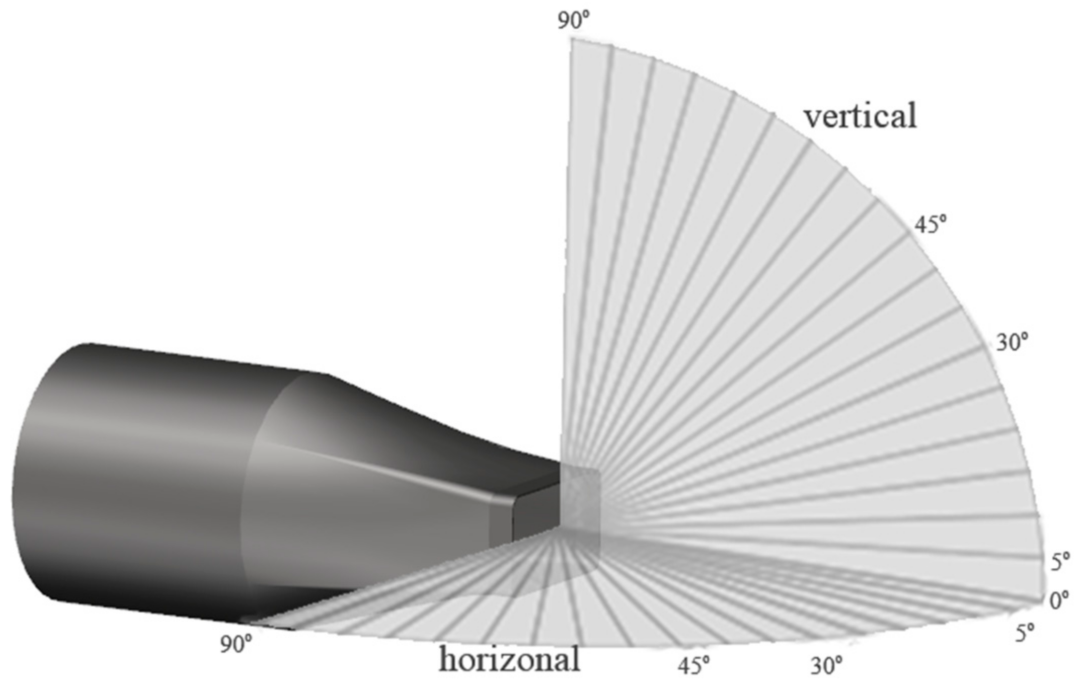
Figure 5 shows the distribution of the infrared radiation detection surfaces. The infrared radiation could be detected from the horizontal detection surface (XOY) and the vertical detection surface (XOZ). The detection points were located at 5° intervals; α = 0° is the direction of the nozzle axis, and α = 90° is the direction perpendicular to the nozzle axis.
6. Analysis of the Calculation Results
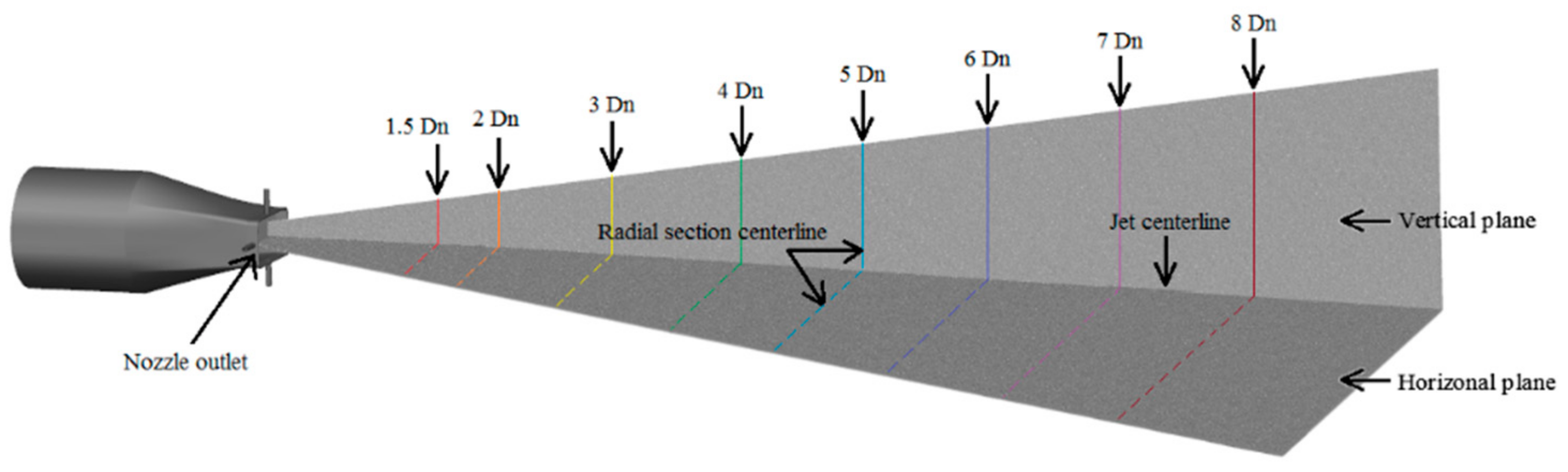
Figure 6 shows the location of the typical axial sections downstream of the horizontal plane and vertical plane, and the intersections of the axial sections are marked from 1.5 Dn to 8 Dn.
6.1. The Distribution of the High-Temperature Zone
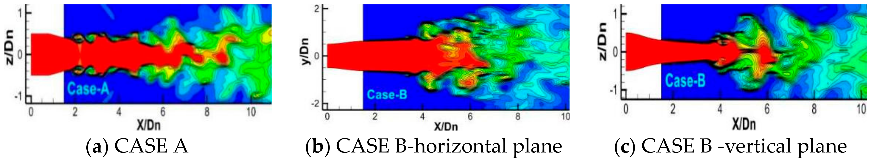
Figure 7 shows the distribution of instantaneous temperature contours on different planes of the CASEs, simulated with LES models. The instantaneous temperature contour mapsin symmetrical plane of CASE A is shown in Figure 7a, and those in horizontal and vertical planes of CASE B are shown in Figure 7b,c. The temperature contours of the three figures have similar distribution.
In Figure 7, it can be seen in the field near the hot jet that the jet column remained stable and that the boundary layer of the jet formed an obvious shear vortex structure. With the development of the jet, the jet column became unstable, and the larger vortex structure dissipated into smaller and richer small vortexes. The vortexes dissipated shorter jet columns and obvious pulsation characteristics.
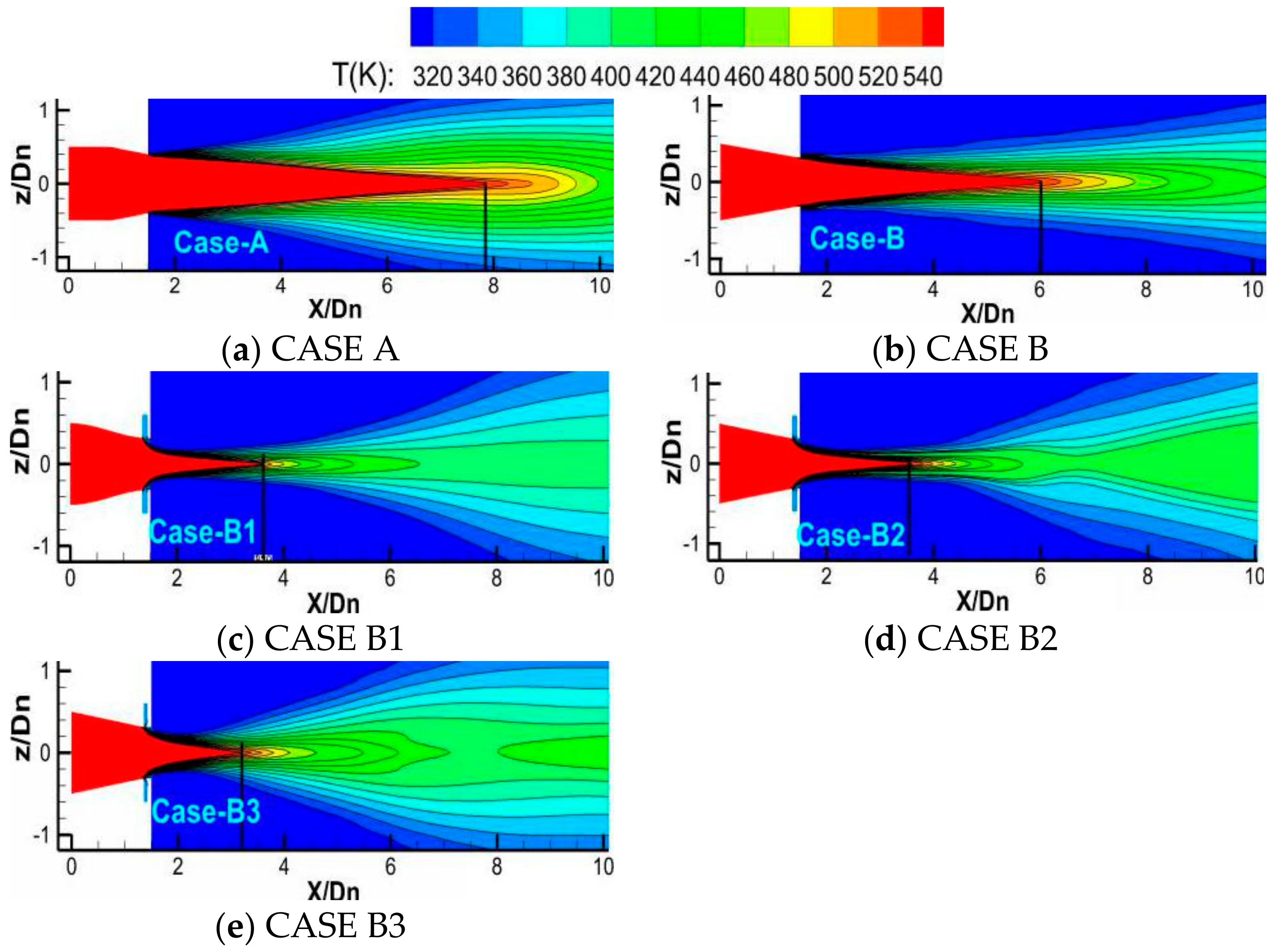
In order to compare the time-averaged temperature characteristics of different cases, Figure 8a–e show the temperature distributions of CASE A, B, B1, B2, and B3 obtained with the Reynolds stress equation model (RSM). The range of high-temperature zones (T > 540 K) are marked by black vertical lines.
Figure 8a presents the temperature contour distribution for CASE A. Figure 8b presents the temperature contour distribution on the vertical plane for CASE B. The results show agreement with CASE A, while the length of the high-temperature zone decreased.
Figure 8c–e show the influence of the configurations on the transverse jets. The circular transverse jets of CASE-B1 resulted in a compressing influence on the hot jet in the vertical plane. The mixing between transverse jets and hot jet increased, which led to the decay of the high-temperature zone and shortened it. Further, when comparing the different transverse jets, the cube jet (CASE B2) and the rectangular jet (CASE B3) showed similar distributions as that of the circular jet (CASE B1). On the other hand, the lengths of the temperature zones decreased. This was caused by the stronger mixing between the hot jets and the non-axis-symmetrical transverse jets.
Figure 9a–e present the temperature distributions of the horizontal planes of CASE A–CASE B3. The results re obviously different from those of vertical planes. In Figure 9b, CASE B shows a contour profile of double peaks, which is different from that of CASE A. This observation shows that the mixing area was enlarged, and the mixing between the ambient and the hot jet was strengthened. This mixing led to a decrease in the high-temperature zone. The length of the high-temperature zone on the vertical and horizontal planes are marked with dotted and continuous lines, respectively. CASE B1 and CASE B2 also showed similar distributions, while CASE B3 showed a reduced high-temperature zone on both vertical and horizontal planes.
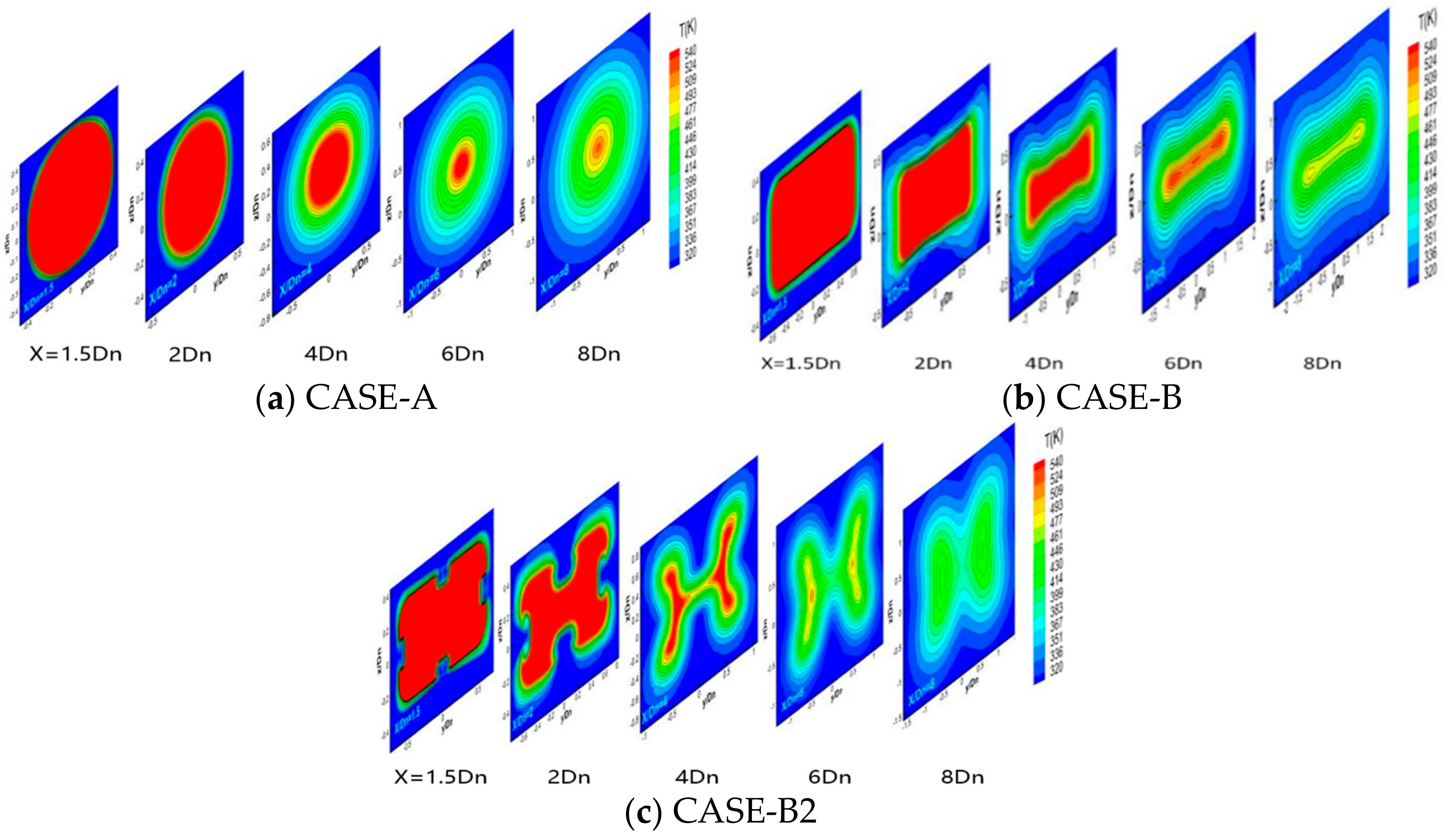
Figure 10 shows the time-averaged temperature distribution of the axial sections for different cases. Compared with CASE A (Figure 10a), the temperature contour map of CASE B (Figure 10b) showed a flatter, rectangular profile, which resulted in a larger contacting area with ambient gas and a stronger mixing ability for the ambient gas.
In Figure 10c, circumferential four-strand transverse jets are introduced. The high-temperature zones in CASE B1 showed four concave zones in the middle of four edges near the nozzle exit, and in the downstream field, the hot jet expanded in both the vertical and the horizontal plane under the extrusion of the transverse jets. The transverse jets significantly increased the mixing between hot jet and ambient gas, which truncated the high-temperature zone downstream, on the vertical and horizontal planes.
6.2. Analysis of the Mixing Mechanism of Flow Field
In this paper, the jet mixing process was numerically investigated by the LES simulation method. For the vortex kernel analysis, the widely used Q criterion was adopted to identify the vortex structures [19].
represents the vorticity amplitude, indicating rotation, S represents the strain rate amplitude, indicating deformation.
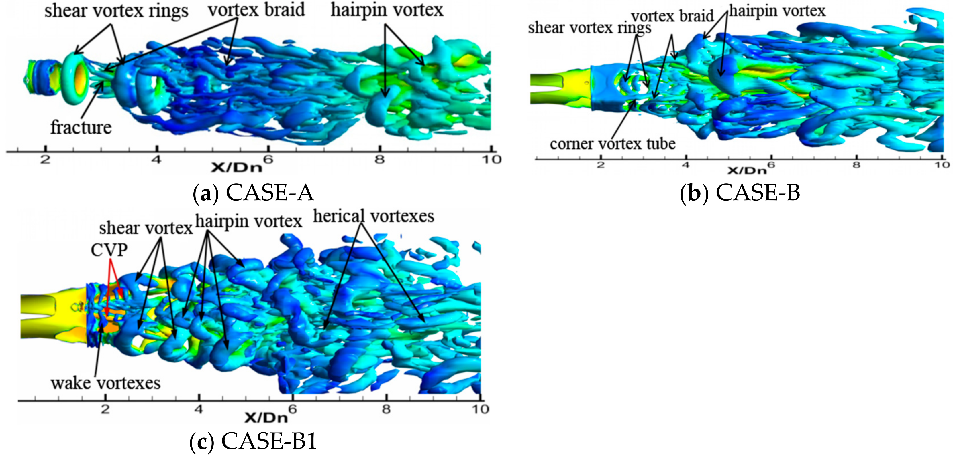
Figure 11 shows the instantaneous coherent structure distributions of the jet vortex Q in downstream regions for each of the CASEs. The vortex structures were mainly composed of a vortex ring, a vortex braid, a hairpin vortex, and a helical vortex. Compared with CASE A, CASE B showed a greatly enhanced strength of shear vortex rings, with abundant vortex braids and hairpin vortices. These structures appeared earlier in position than similar structures in CASE A.
In Figure 11c, the discontinuity of the velocity for the transverse jets and the hot jet in CASE-B1 resulted in strong reverse rotating vortex pairs (CVP) that showed inward entrainment in the shear layer. A series of shear vortex structures were introduced, and weak wake vortexes were also produced on the leeward surface, which induced an extensive mixing, increasing near the nozzle exit. Downstream, helical vortices appeared, resulting in stronger mixing. The variation of the injection shape mainly affected the near-field mixing degree, and among the three different transverse jets schemes studied in the present paper, Case B3 appeared to be the optimal one. The rectangular jet increased the mixing area, leading to a stronger CVP.
6.3. Infrared Radiation Intensity Distribution
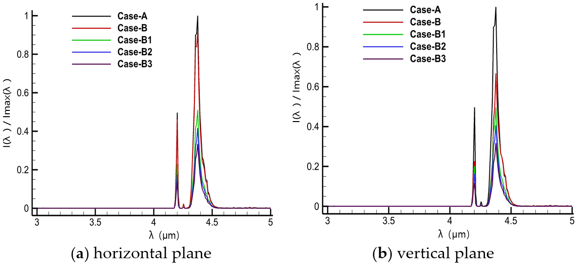
Figure 12 presents the infrared radiation intensity spectrum of the hot jet in the 3–5 µm bands, which was measured at 60°. In the 4.16~4.6 µm band, the absorption and emission of CO2 and H2O induced wave peaks and troughs. The distribution of spectral radiation in CASE-B was similar to that of CASE-A, while the radiation intensity magnitude of CASE-B was smaller. When the transverse jets were applied, the infrared spectrum radiation intensity was clearly reduced for both detective planes. This is illustrated for CASE B1, CASE B2, and CASE B3, while the magnitude of the three decreased in the 4.16~4.6 µm band.
The infrared radiation intensity is defined as:
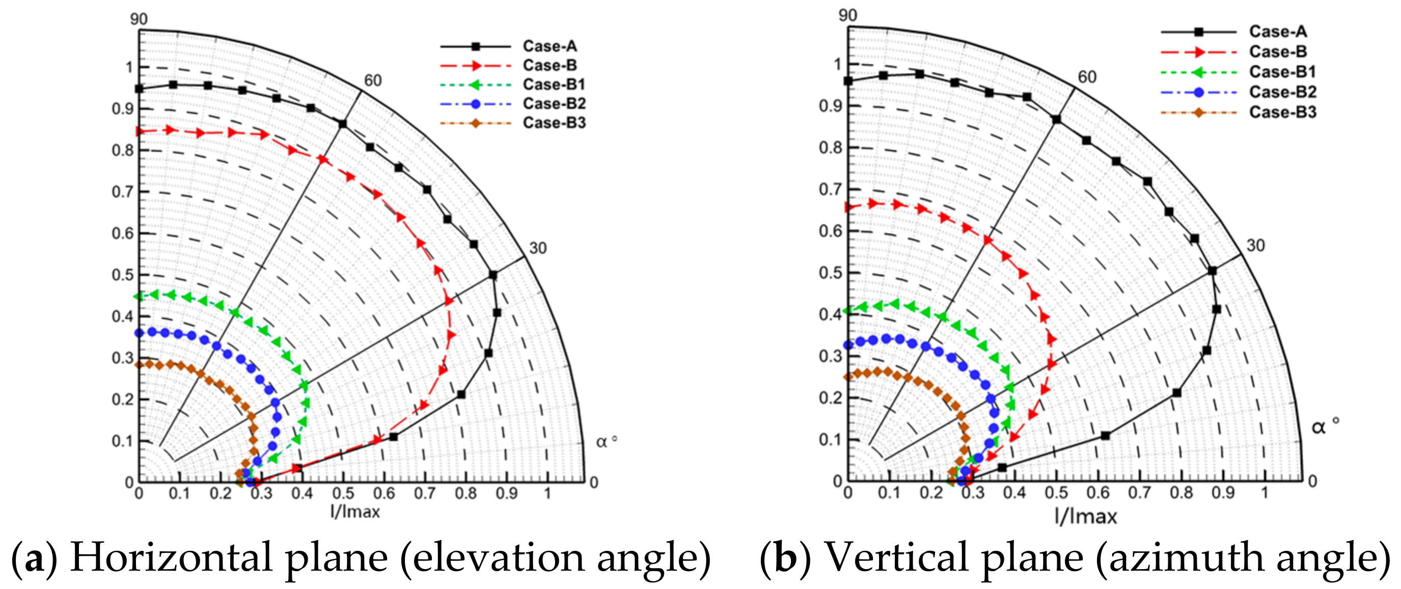
In formula (1), the infrared radiation intensity can be integrated in the infrared spectrum radiation. is the spectral radiation intensity, while is the lower and is the upper limit of the 3–5 microwave band. The results are dimensionless and based on the maximum radiation intensity Imax of CASE-A. The results for the horizontal and the vertical planes are shown in Figure 13a,b.
Figure 13 presents the infrared radiation intensity of the hot jet in the 3–5 microwave regions for detected angles from 0 to 90°. The infrared radiation intensity, I, of the hot jet increased first and then decreased in all CASEs. The infrared radiation intensity reached a high value between 30 and 60°.
The infrared radiation intensity of CASE-A was consistent on the horizontal and vertical planes because of its symmetrical geometrical characteristics. For CASE-B, the infrared radiation intensity distribution was in good agreement with that of CASE-A, while the intensity was lower for both planes. Further, the intensity on the horizontal plane was slightly higher than that on the vertical plane. The infrared radiation intensity distribution for CASE-B1, CASE B2, and CASE B3 was also in good agreement with that of CASE B. The intensity on both planes was also lower than those observed for CASE-B and decreased on both the horizontal and the vertical plane.
7. Conclusions
In this paper, a circular convergent nozzle and a circular-rectangular nozzle were designed. Using the latter nozzle, three different circumferential transverse jets were introduced. The heat transfer and infrared radiation characteristics in subsonic situations were numerically investigated. The main conclusions of the research presented in this paper are the following:
- (1)
- Compared with the axisymmetric nozzle, the circular-to-rectangular nozzle induced great mixing and led to a decrease of the high-temperature zone. The induced transverse jets resulted in a mixing enhancement of the hot jet. The high temperature-zones were shortened.
- (2)
- By changing from a circular to a rectangular nozzle, abundant vortices occurred in the near field of the hot jet. Shear vortices near the corners developed rapidly. Hairpin vortices, which formed near the nozzle exit, dissipated quickly.
- (3)
- The transverse jets induced CVP structures, resulting in abundant near-field vortices, increased vortex development speed, and enhanced pulsation of the mainstream boundary layer. They even expanded the penetration range, which led to the instability of the hot jet. Furthermore, the lap winding frequency was higher, large-scale hairpin vortices formed earlier, and the influenced range was wider.
- (4)
- As the transverse jets were introduced into the circular-rectangular nozzle, the infrared radiation significantly decreased. For all angles, when circular transverse jets were introduced, the infrared radiation decreased on the horizontal and vertical planes. Furthermore, when cube and rectangular transverse jets were introduced, the infrared radiation decreased by 28.2% on the horizontal plane and by 25.3% on the vertical plane.
Author Contributions
Introduction: B.Z., Z.L.; Physical Model: B.Z., Z.L., J.Z.; Computational Domain and Boundary Conditions: Z.L., J.Z., S.Y.; Meshes Generation and Independence: J.Z., S.Y.; Numerical Simulation Method: B.Z., Z.L., Analysis of the Calculation Results: B.Z., Z.L., H.J. All authors have read and agreed to the published version of the manuscript.
Funding
This research was funded by National Science and Technology Major Project (J2019-III-0009-0053) and Aeronautical Science Foundation of China (20200027052002).
Institutional Review Board Statement
Not applicable.
Informed Consent Statement
Not applicable.
Data Availability Statement
Some or all data, models, or code generated or used during the study are available from the corresponding author by request.
Conflicts of Interest
The authors declare no conflict of interest.
References
- BAE Systems. Stealth Technology; BAE Systems: Farnborough, UK, 2004. [Google Scholar]
- Freund, J.B.; Moin, P. Jet mixing enhancement by high-amplitude Fluidic actuation. AIAA J. 2000, 38, 1863–1870. [Google Scholar] [CrossRef] [Green Version]
- Knowles, K.; Saddington, A.J. A review of jet mixing enhancement for aircraft propulsion applications. Proc. Inst. Mech. Eng. Part G J. Aerospace Eng. 2006, 220, 103–127. [Google Scholar] [CrossRef]
- Parekh, D.E.; Kibens, V.; Glezer, A.; Wiltse, J.M.; Smith, D.M. Innovative jet flow control: Mixing enhancement experiments. In Proceedings of the 34th Aerospace Sciences Meeting and Exhibit, Reno, NV, USA, 15–18 January 1996; pp. 96–308. [Google Scholar]
- Mahjoub, S.N.; Habli, S.; Bournot, H.; Le Palec, G. The near field in the mixing of a three-dimensional inclined pollutant jet with a crossflow. J. Enhanc. Heat Transf. 2012, 19, 161–178. [Google Scholar] [CrossRef]
- Gretta, W.J.; Smith, C.R. The Flow Structure and Statistics of a Passive Mixing Tab Transactions of the Asme. J. Fluids Eng. 1993, 115, 255–263. [Google Scholar] [CrossRef]
- Behrouzi, P.; McGuirk, J.J. Jet Mixing Enhancement Using Fluid Tabs; AIAA-2004–2401. In Proceedings of the 2nd AIAA Flow Control Conference, Portland, OR, USA, 28 June–1 July 2004. [Google Scholar]
- Du, L.W.; Liu, Y.H.; Li, T. Numerical Predictions of Scarfing on Performance of S-Shaped Nozzle with Asymmetric Lobe. J. Propuls. Power 2015, 31, 604–618. [Google Scholar] [CrossRef]
- Sheng, Z.Q.; Chen, S.C.; Wu, Z.; Huang, P.L. High mixing effectiveness lobed nozzles and mixing mechanisms. Sci. China Technol. Sci. 2015, 58, 1218–1233. [Google Scholar] [CrossRef]
- Callender, B.; Gutmark, E.J.; Martens, S. Flow field characterization of coaxial conical and serrated (chevron) nozzles. Exp. Fluids 2010, 48, 637–649. [Google Scholar] [CrossRef]
- Suvagiya, M.; Sharma, S.D. Numerical investigation on the effect of geometric parameters of chevron nozzle on generation of streamwise vortices in high subsonic jets. J. Aerosp. Sci. Technol. 2019, 71, 225–230. [Google Scholar]
- Eri, Q.; Hong, L.; Li, T.; Wang, Q.; Wang, M. Numerical Simulations of Mixing Enhancement in Subsonic Jet Using High-Momentum Synthetic Jets. J. Propuls. Power 2016, 32, 1095–1103. [Google Scholar] [CrossRef]
- Karagozian, A.R. Transverse jets and their control. Prog. Energy Combust. Sci. 2010, 36, 531–553. [Google Scholar] [CrossRef]
- Kamran, M.A.; Mcguirk, J.J. Subsonic Jet Mixing via Active Control Using Steady and Pulsed Control Jets. AIAA J. 2015, 49, 712–724. [Google Scholar] [CrossRef]
- Andreopoulos, J. On the structure of jets in a crossflow. J. Fluid Mech. 2006, 157, 163–197. [Google Scholar] [CrossRef]
- Behrouzi, P.; Mcguirk, J. Effect of Tabs on Rectangular Jet Plume Development. J. Propuls. Power 2009, 25, 930–939. [Google Scholar] [CrossRef]
- Gevorkyan, L.; Shoji, T.; Getsinger, D.R.; Smith, O.I.; Karagozian, A.R. Transverse jet mixing characteristics. J. Fluid Mech. 2016, 790, 237–274. [Google Scholar] [CrossRef]
- Kamran, M.A. Manipulation of High Mach Number Shear Layers Using Control Jets. Ph.D. Thesis, Loughborough University, Loughborough, UK, 2009. [Google Scholar]
- Kelso, R.M.; Lim, T.; Perry, A.E. New experimental observation of vortical motions in transverse jets. Phys. Fluids 1998, 10, 2427–2429. [Google Scholar] [CrossRef]
- Bidan, G.; Nikitopoulos, D.E. On steady and pulsed low-blowing-ratio transverse jets. J. Fluid Mech. 2013, 714, 393–433. [Google Scholar] [CrossRef]
- McClinton, C.R. The Effect of Injection Angle on Interaction between Sonic Secondary Jets and a Supersonic Free Stream; NASA TND-6669; NASA: Washington, DC, USA, 1972. [Google Scholar]
- Gruber, M.R.; Nejadt, A.S.; Chen, T.H.; Dutton, J.C. Mixing and Penetration Studies of Sonic Jets in a Mach 2 Free stream. J. Propuls. Power 2012, 11, 315–323. [Google Scholar] [CrossRef]
- Zhang, B.; Hong, Q.; Bai, Y.; Li, J.; Ji, H. Numerical Investigation of Heat Transfer in Film Layer under Supersonic Condition. Ther. Sci. 2020, 24, 2279–2288. [Google Scholar] [CrossRef]
- Zhang, B.; Chen, Y.X.; Wang, Z.G.; Li, J.Q.; Ji, H.H. Influence of Mach number of Main Flow on Film Cooling Characteristics under Supersonic Condition. Symmetry 2021, 13, 127. [Google Scholar] [CrossRef]
- Kobayashi, K.; Bowersox, R.D.; Srinivasan, R.; Tichenor, N.R.; Carter, C.D.; Ryan, M.D. Experimental and Numerical Studies of Diamond-Shaped Injector in a Supersonic Flow. J. Propuls. Power 2010, 26, 373–376. [Google Scholar] [CrossRef]
- Yang, H.; Li, G.N.; Zhou, H.; Cen, K.F. Large eddy simulation of transverse elliptic jet. J. Zhejiang Univ. 2007, 41, 1181–1185. [Google Scholar]
- Kong, B.; Li, T.; Eri, Q. Large eddy simulation of turbulent jet controlled by two pulsed jets: Effect of forcing frequency. Aerospace Sci. Technol. 2019, 89, 356–369. [Google Scholar] [CrossRef]
- Zhou, Y.; Wang, Q.; Li, Y. A new model to simulate infrared radiation from an aircraft exhaust system. Chin. J. Aeronaut. 2017, 30, 651–662. [Google Scholar] [CrossRef]
- Liu, L.H. Backward Monte Carlo Method Based on Radiation Distribution Factor. J. Thermophys. Heat Transf. 2004, 18, 151–153. [Google Scholar] [CrossRef]
- Niu, Q.L.; Fu, D.B.; Dong, S.K.; Tan, H.P. A simplified model for fast estimating infrared thermal radiation of low-altitude under-expanded exhaust plumes. Int. J. Heat Mass Transf. 2019, 136, 276–287. [Google Scholar] [CrossRef]
Figure 1.
Physical models of CASEs.

Figure 2.
Computational domain.

Figure 3.
Meshes for flow computation.

Figure 4.
Validity of the meshes and numerical simulation method.

Figure 5.
Sketch of the detecting orientations.

Figure 6.
Typical downstream sections.

Figure 7.
Transient temperature contour on planes.

Figure 8.
Temperature contour on the vertical plane.

Figure 9.
Mean temperature contour on the horizontal plane.

Figure 10.
Mean temperature contours on the radial plane.

Figure 11.
Distribution of dimensionless core areas along the axial direction at t = 0.02 s.

Figure 12.
Dimensionless spectral radiant intensity of a hot jet at a detective angle a = 60°.

Figure 13.
Dimensionless radiation intensity.


Table 1.
Illustration of the models.
| Model-A | Model-B | Model-B1 | Model-B2 | Model-B3 |
|---|---|---|---|---|
| Asymmetrical nozzle | Circular-rectangular nozzle | Model-B with Round transvers jets | Model-B With square transvers jets | Model-B With rectangular transvers jets |
Publisher’s Note: MDPI stays neutral with regard to jurisdictional claims in published maps and institutional affiliations. |
© 2022 by the authors. Licensee MDPI, Basel, Switzerland. This article is an open access article distributed under the terms and conditions of the Creative Commons Attribution (CC BY) license (https://creativecommons.org/licenses/by/4.0/).
Share and Cite
MDPI and ACS Style
Zhang, B.; Lin, Z.; Zhang, J.; Yang, S.; Ji, H. Numerical Investigation of the Flow and Infrared Radiation Characteristics of Nozzles with Transverse Jets of Different Shapes. Processes 2022, 10, 763. https://doi.org/10.3390/pr10040763
AMA Style
Zhang B, Lin Z, Zhang J, Yang S, Ji H. Numerical Investigation of the Flow and Infrared Radiation Characteristics of Nozzles with Transverse Jets of Different Shapes. Processes. 2022; 10(4):763. https://doi.org/10.3390/pr10040763
Chicago/Turabian StyleZhang, Bo, Ziqiang Lin, Jun Zhang, Sheng Yang, and Honghu Ji. 2022. "Numerical Investigation of the Flow and Infrared Radiation Characteristics of Nozzles with Transverse Jets of Different Shapes" Processes 10, no. 4: 763. https://doi.org/10.3390/pr10040763
Note that from the first issue of 2016, this journal uses article numbers instead of page numbers. See further details here.