
Transient Characteristics of Three-Dimensional Flow in a Centrifugal Impeller Perturbed by Simple Pre-Swirl Inflow

Abstract
:1. Introduction
2. Numerical Setup
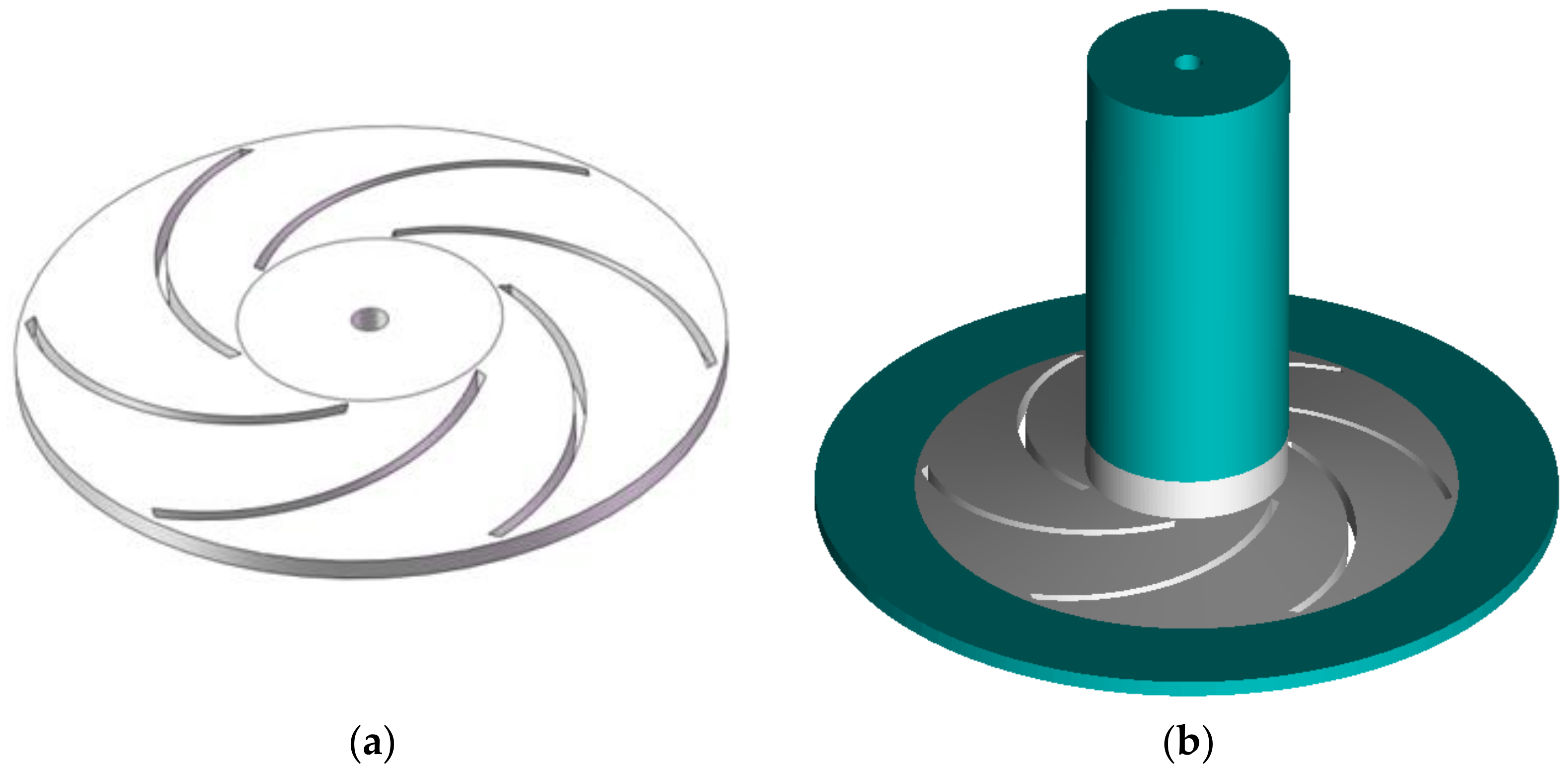
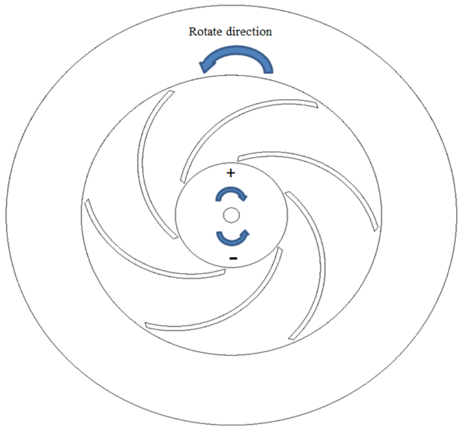
2.1. Physical Model
2.2. Numerical Methods
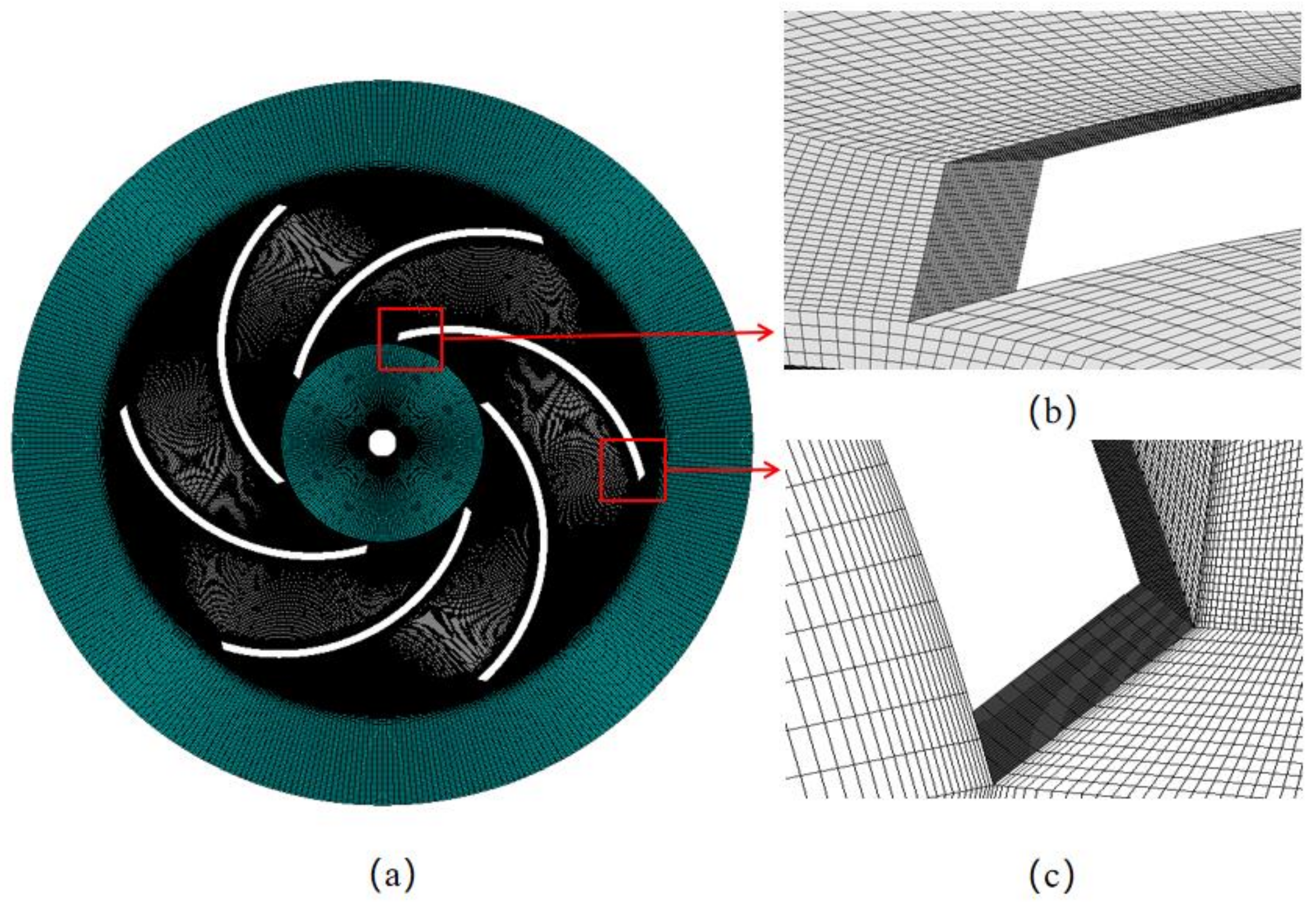
2.3. Grid Sensitivity Study
3. Results and Discussion
3.1. Development of Pre-Swirl Inflow
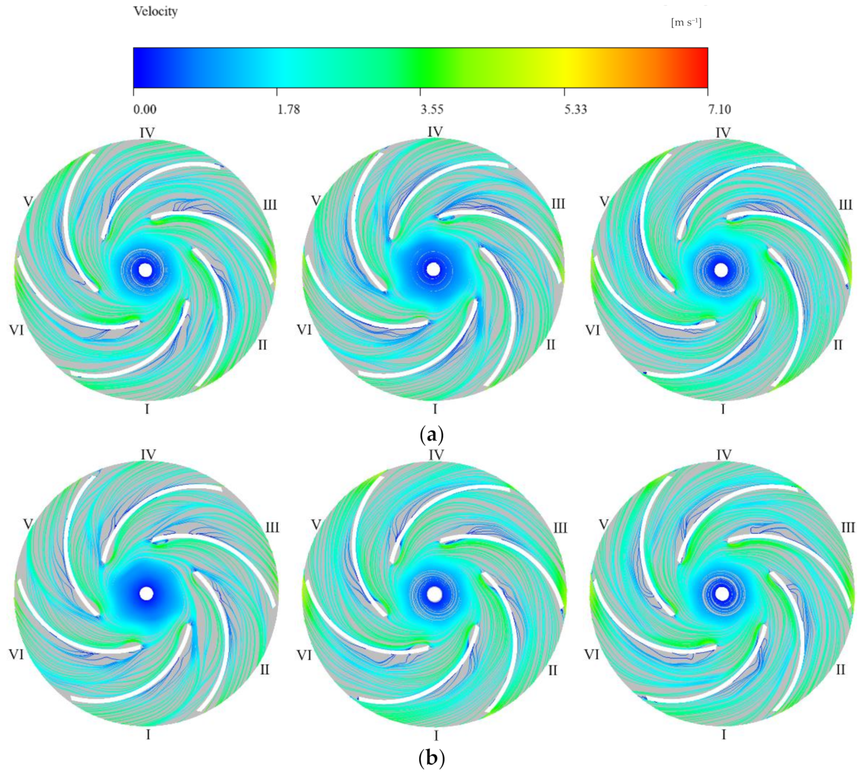
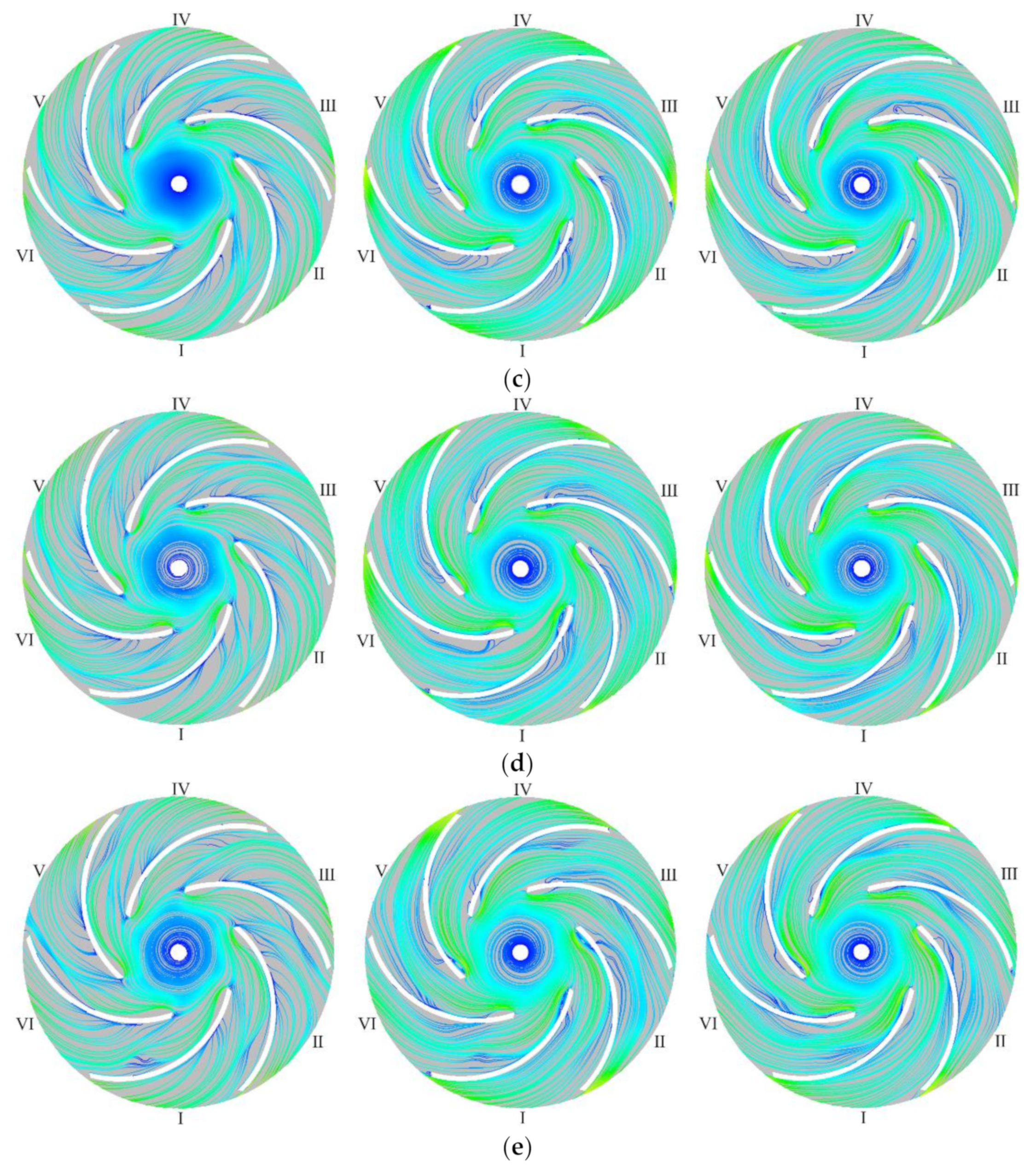
3.2. General Flow Patterns
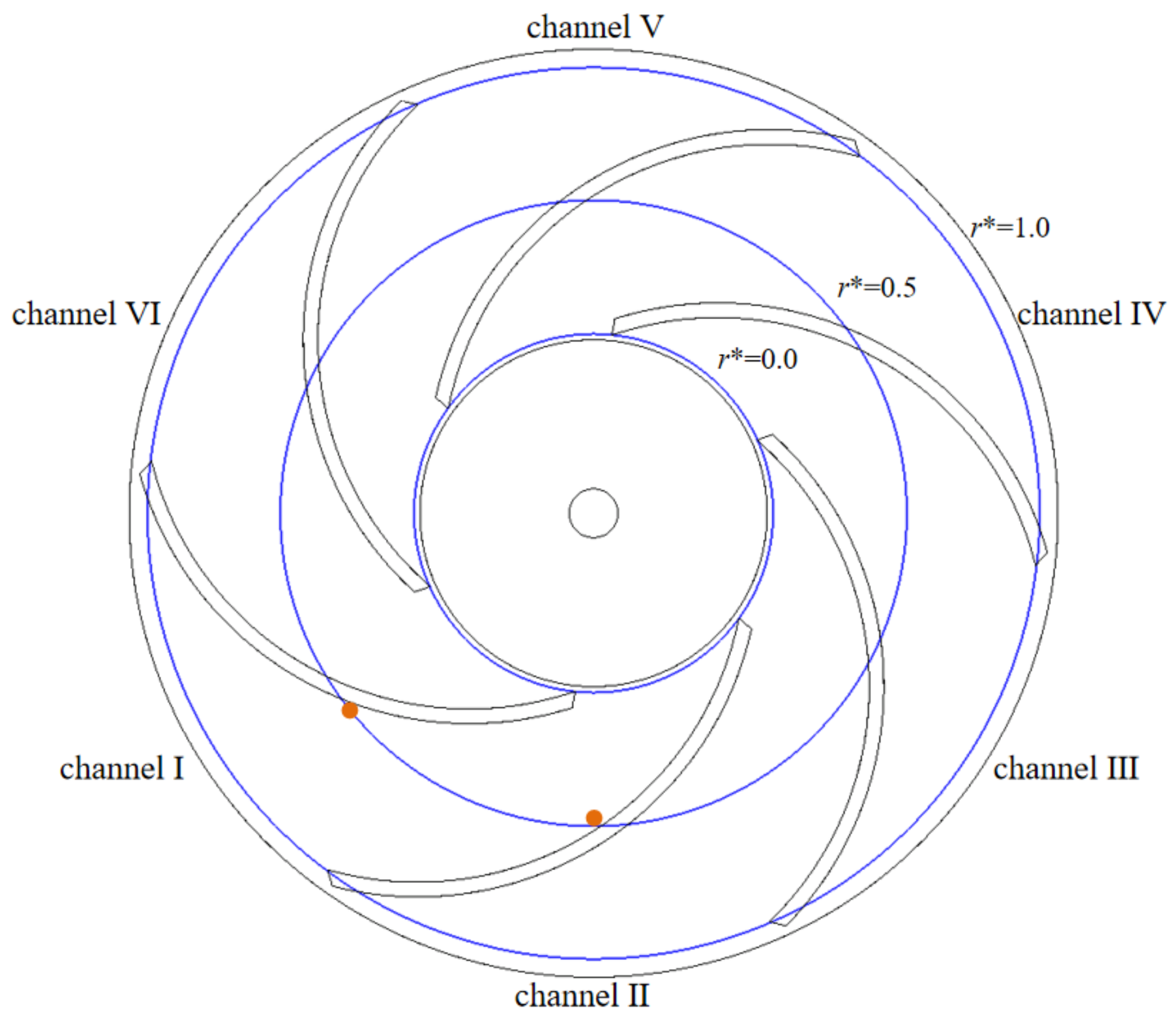
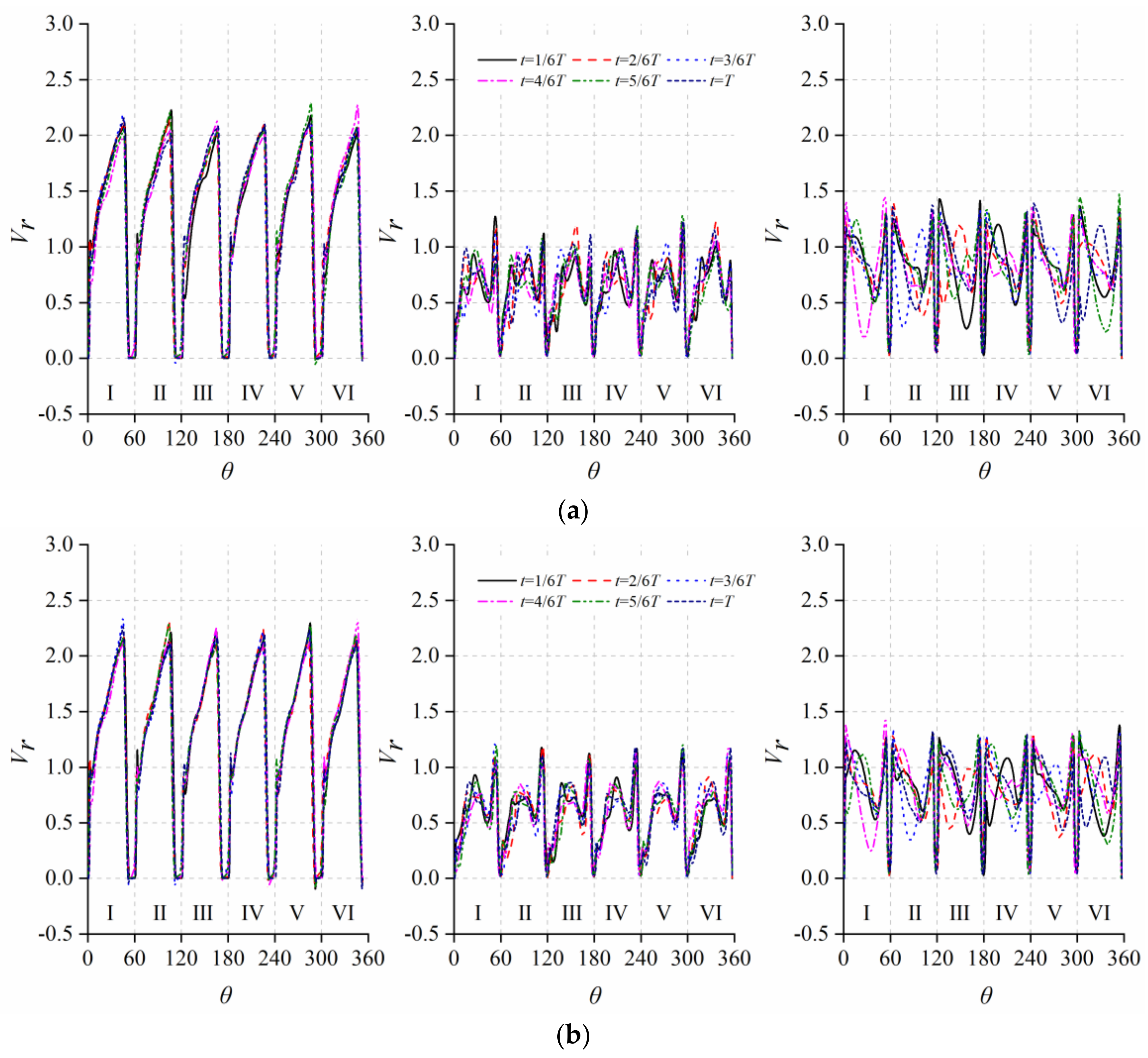
3.3. Three-Dimensional Flow: Blade-to-Blade Distribution
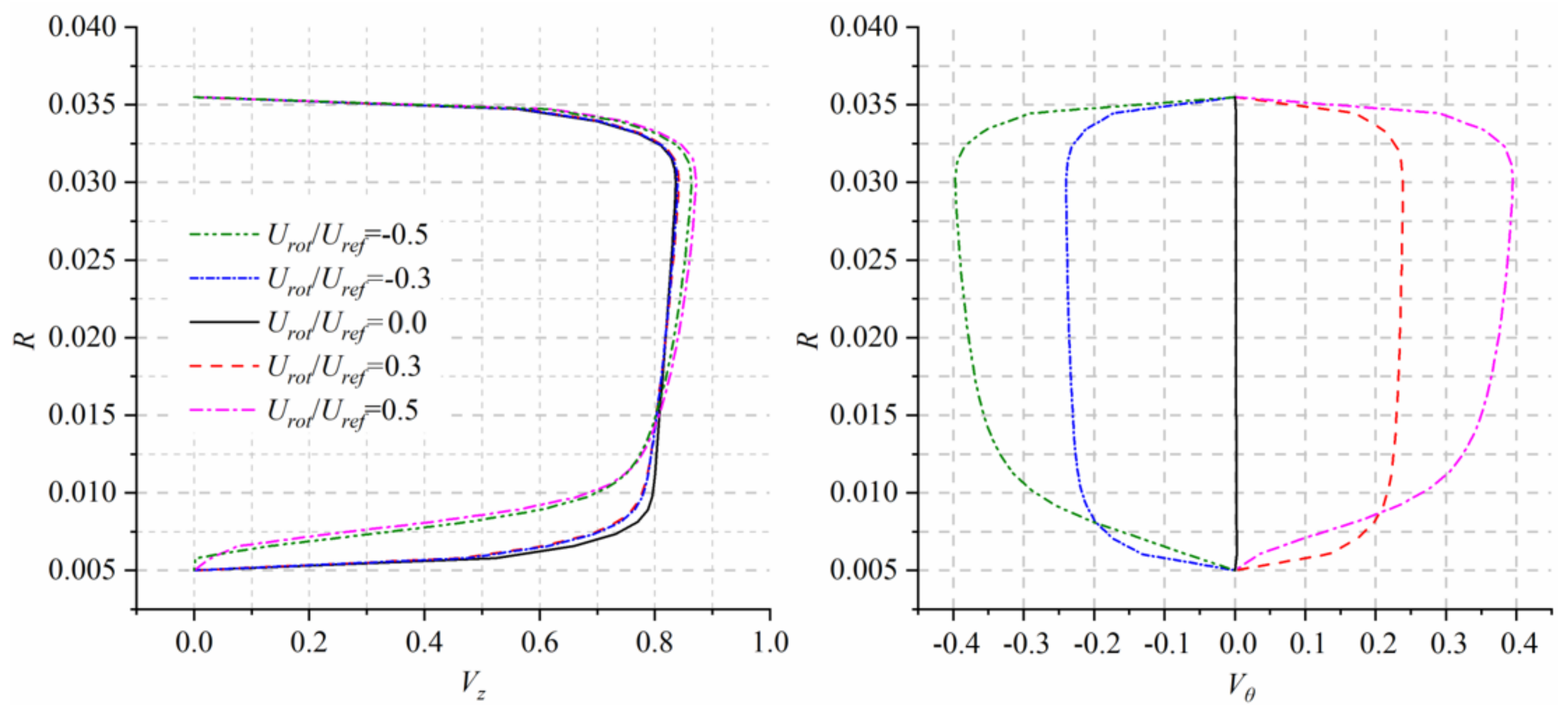
3.4. Three-Dimensional Flow: Hub-to-Shroud Distributions
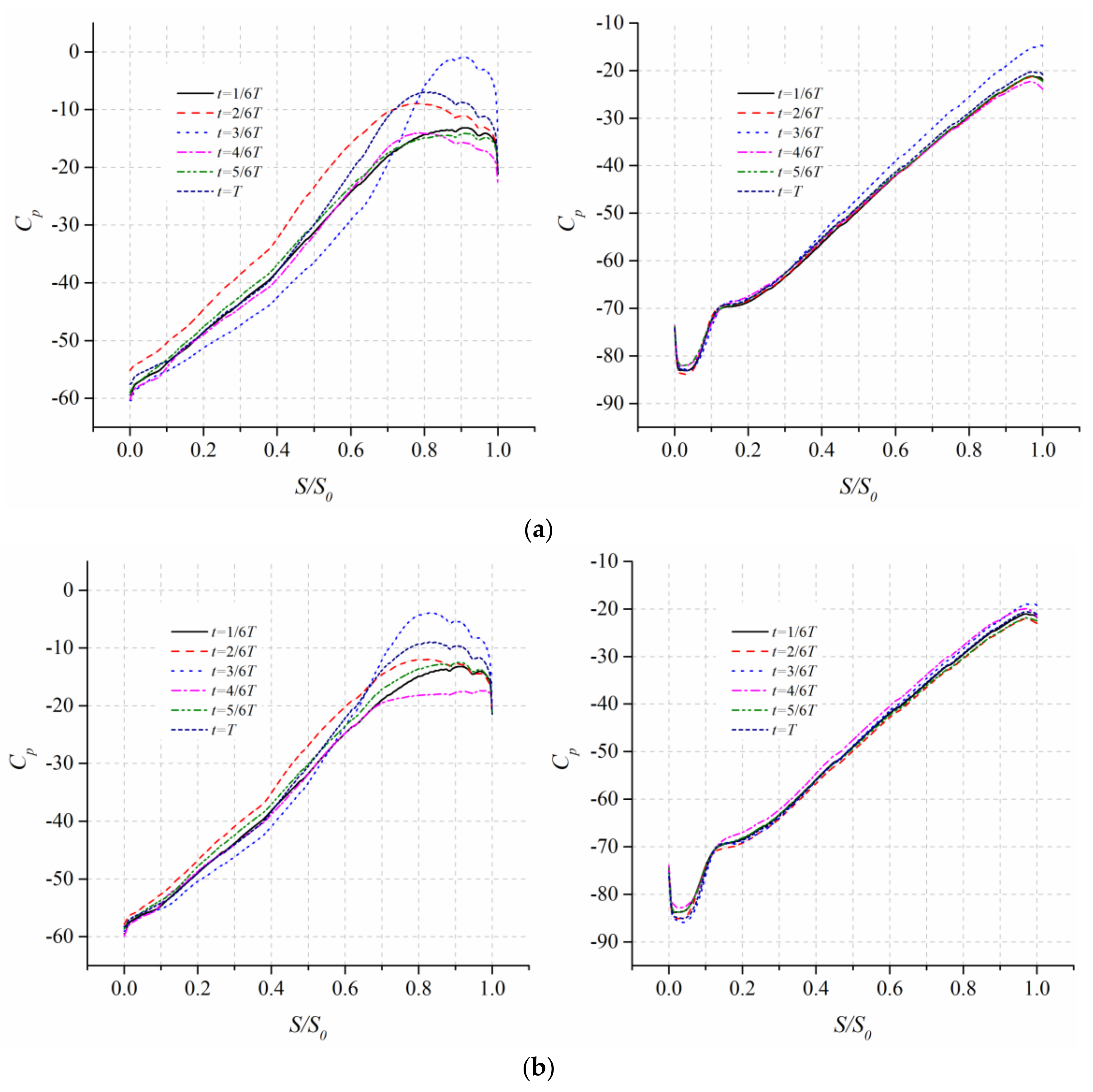
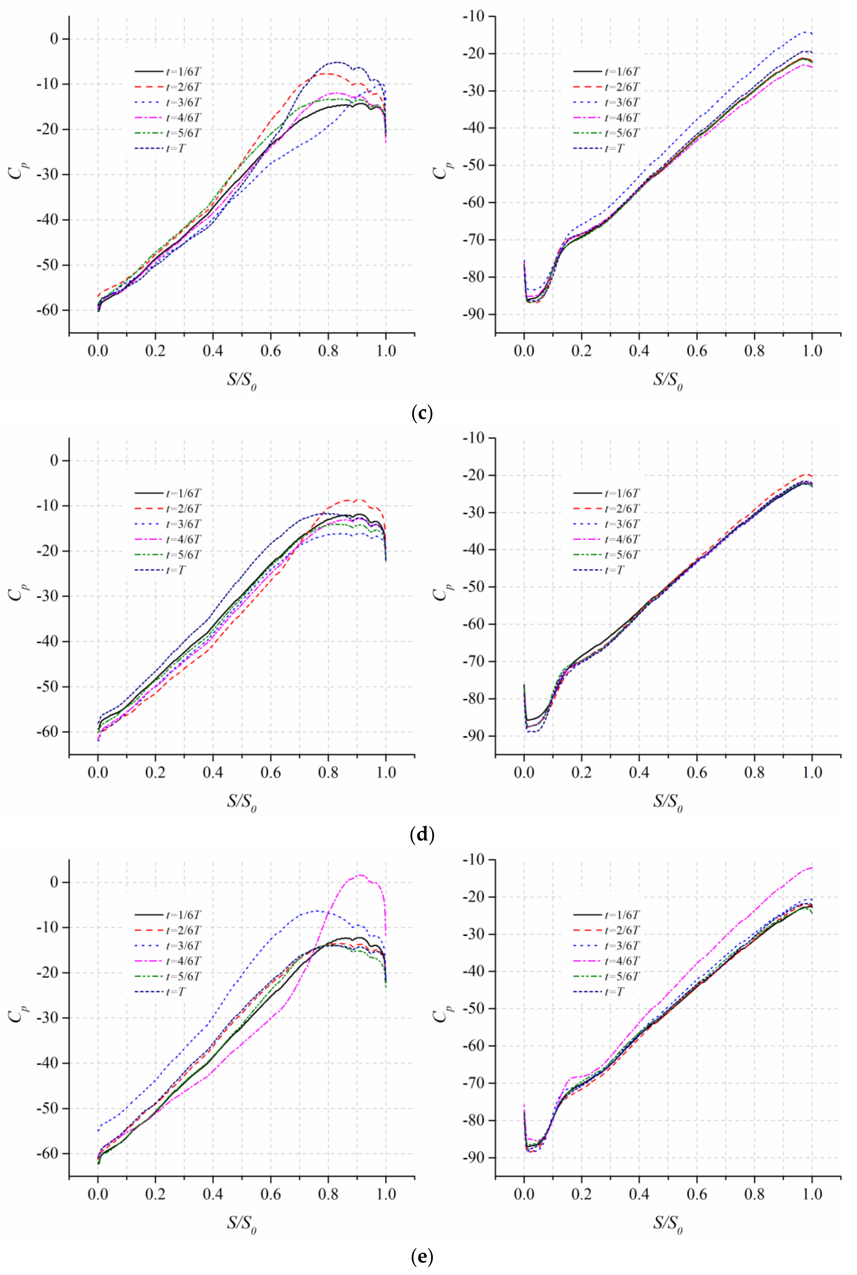
3.5. Pressure Gradient Field on the Blade Surfaces
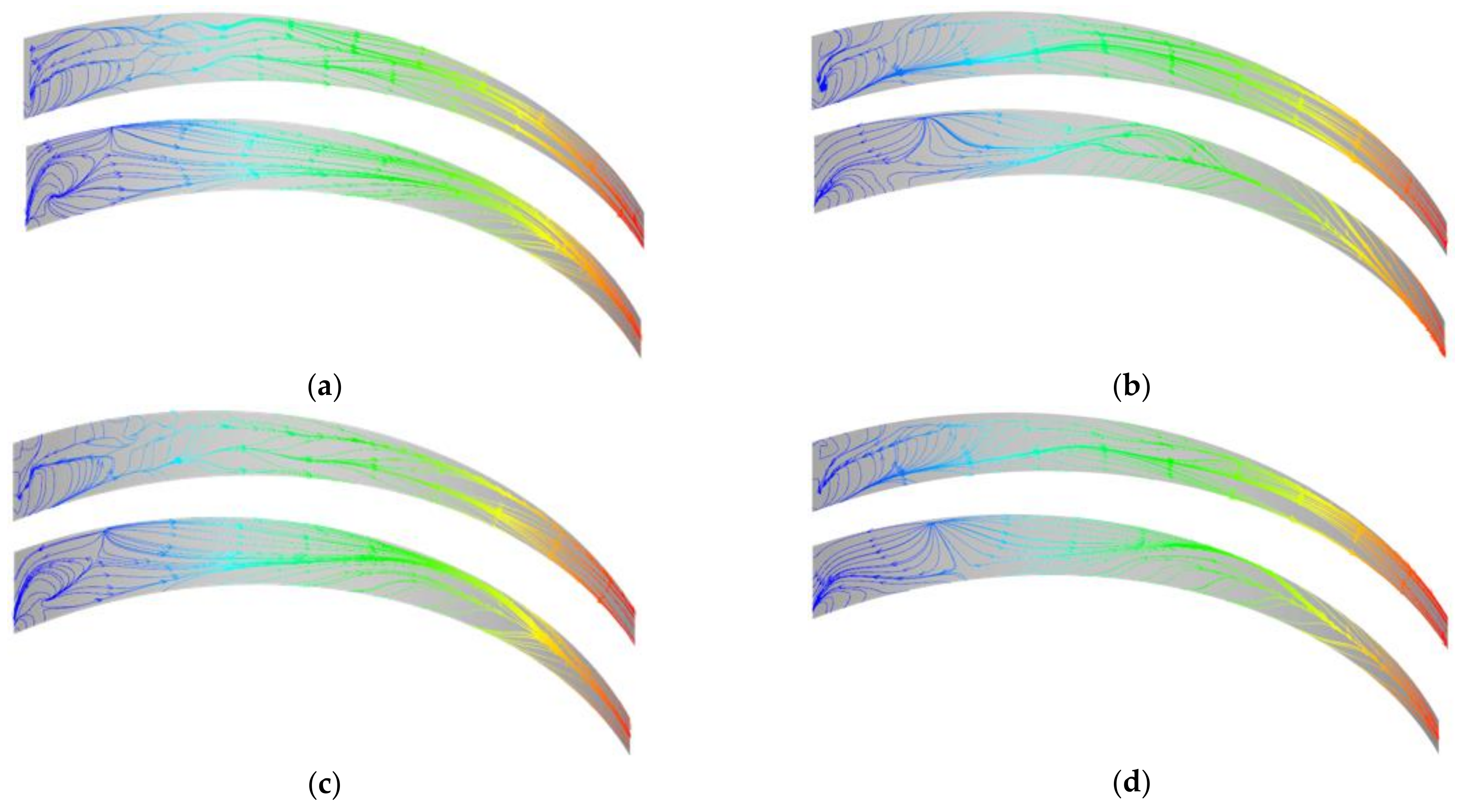
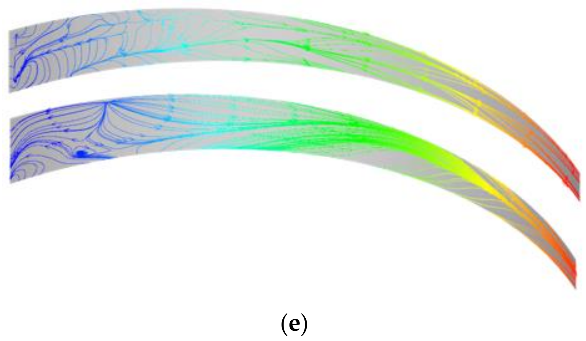
3.6. Topology of Limiting Streamlines
4. Conclusions
- (1)
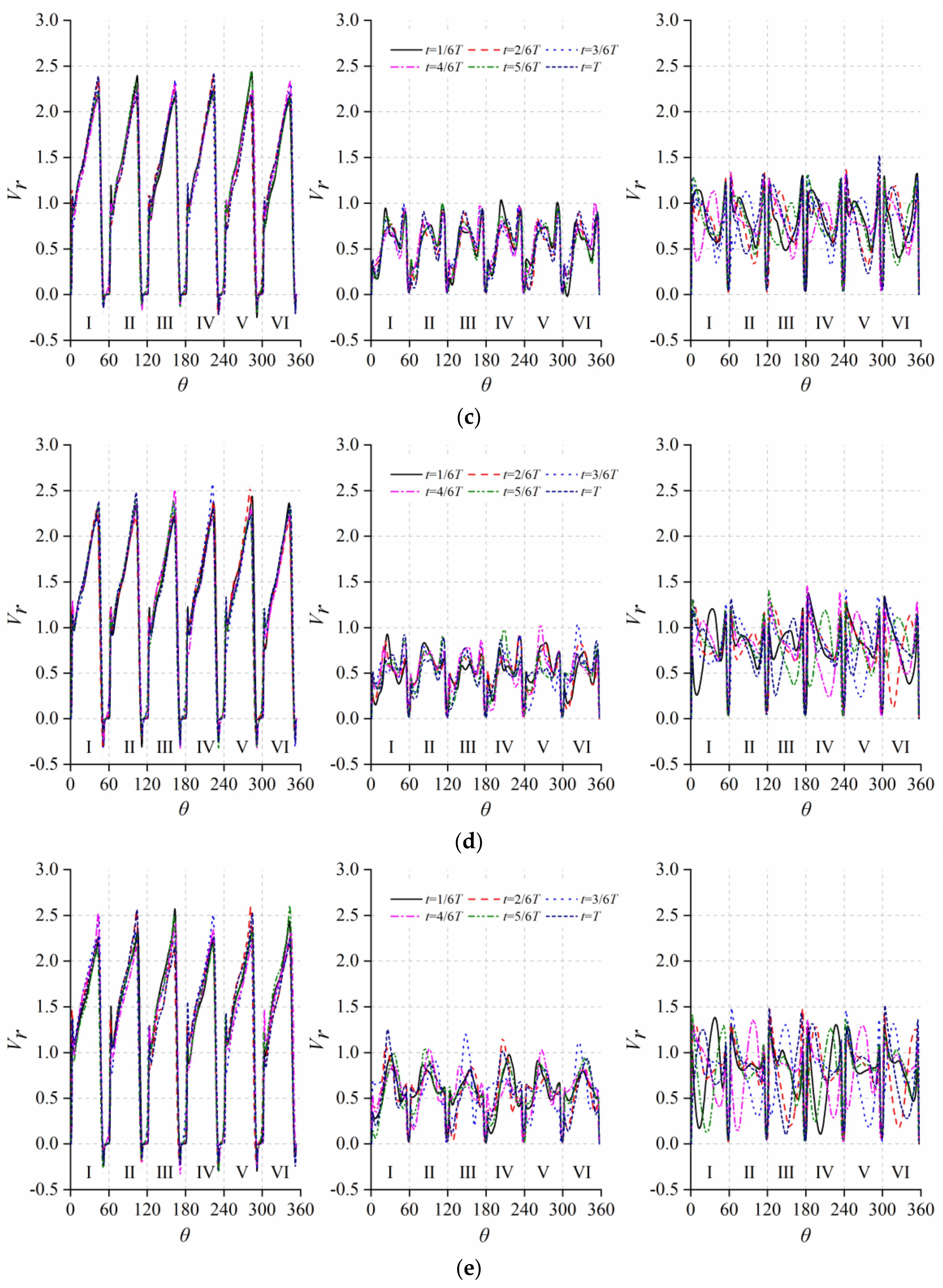
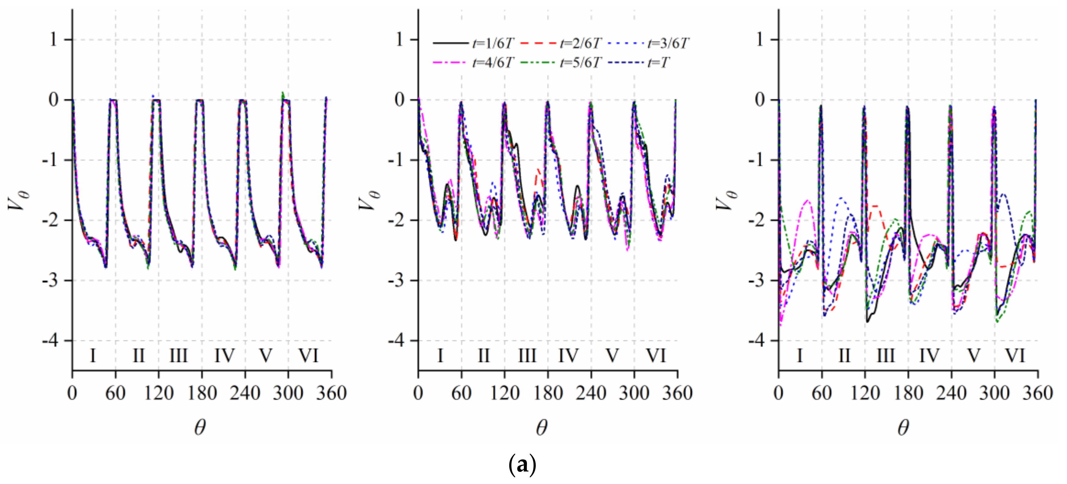
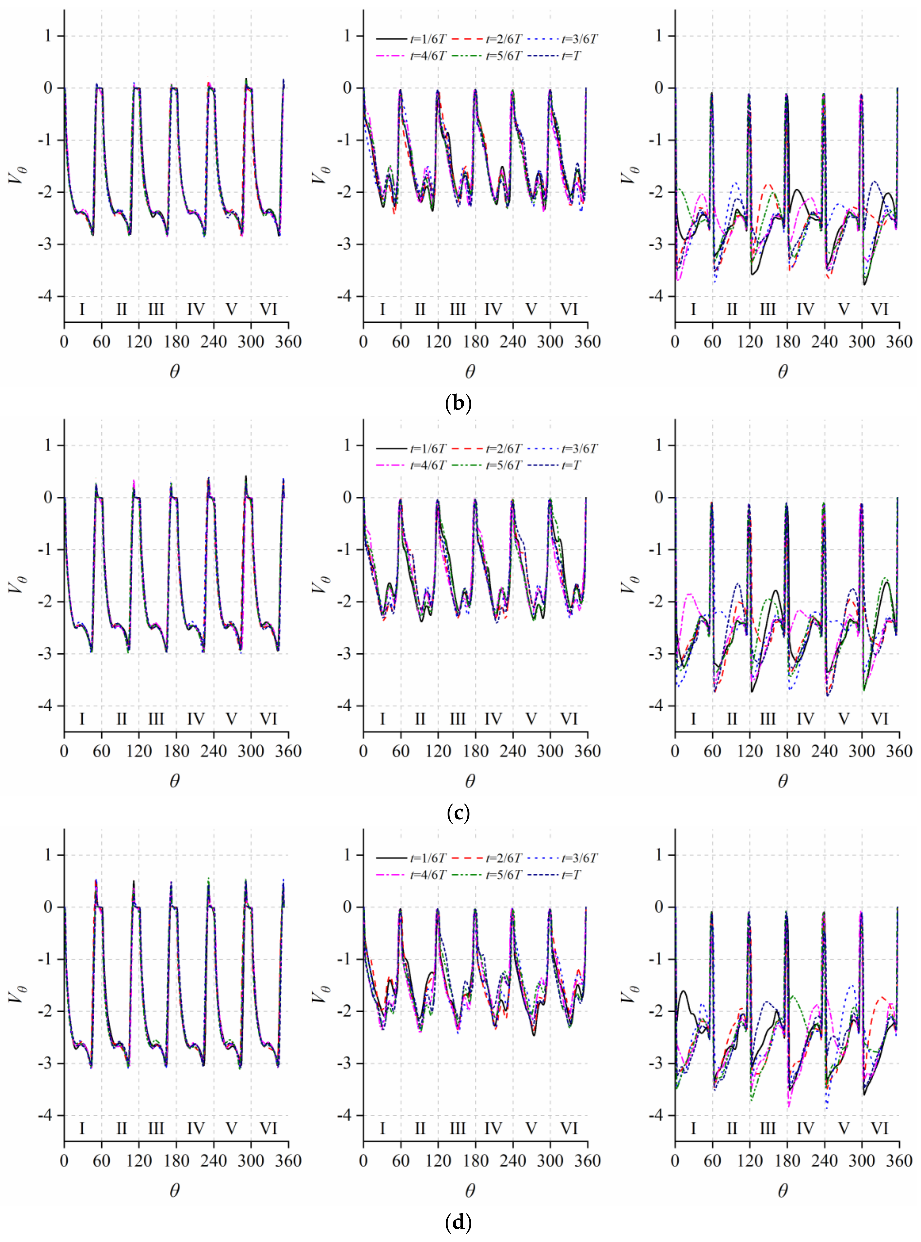
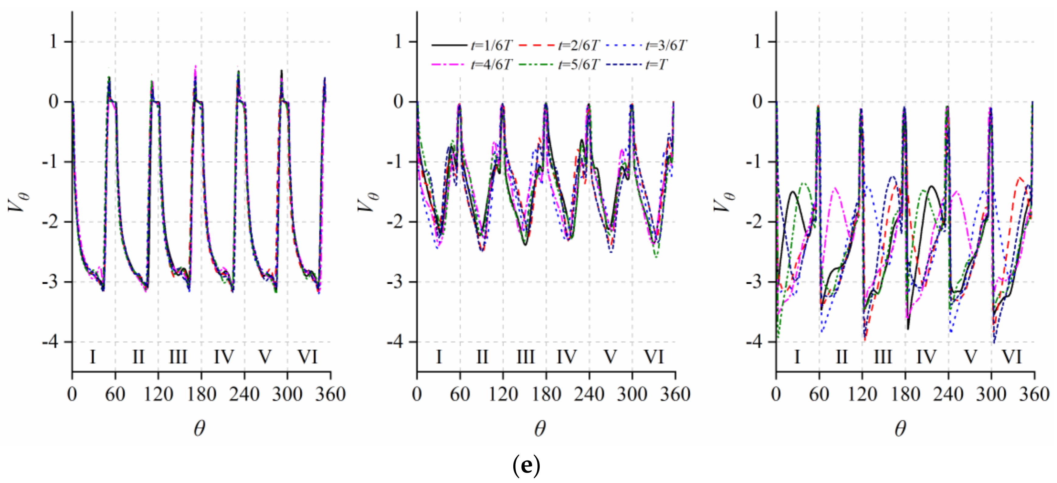
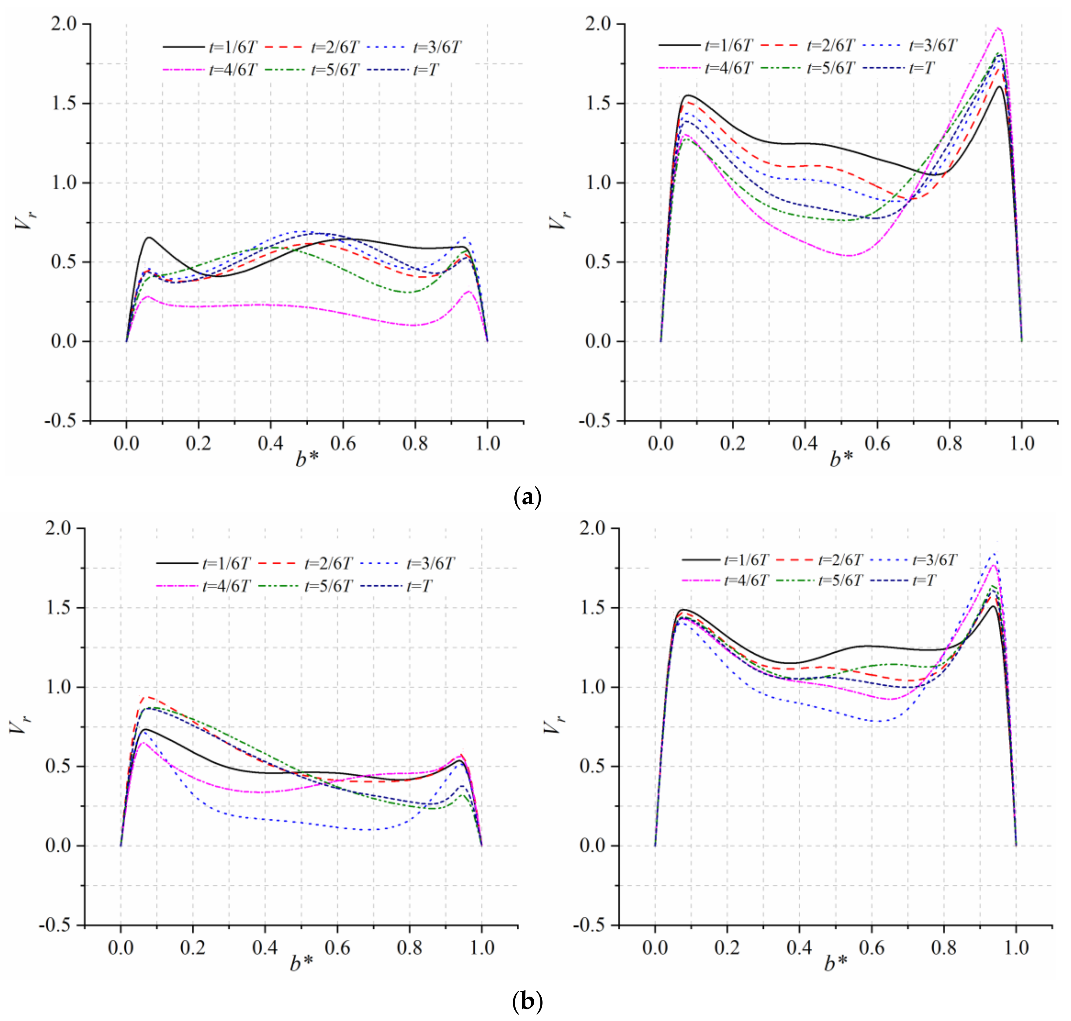
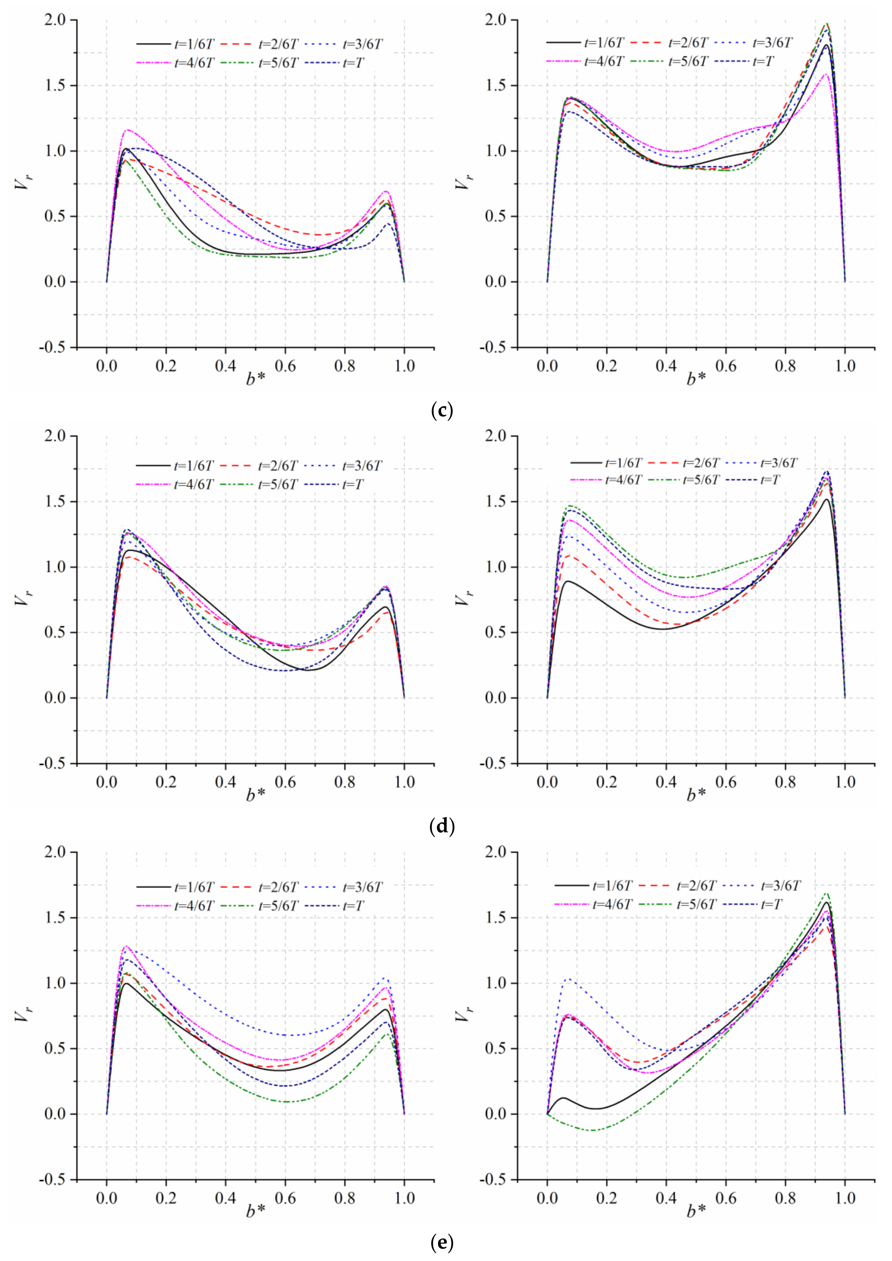
- The temporal fluctuation of flow is weak at the inlet of the blade channels (r* = 0.0). Close to the suction surface, the magnitude of radial velocity Vr for the counter-rotating inflow is 15–25% larger compared to the co-rotating inflow cases. The peak magnitude reaches the maximum about 2.5 m/s near the suction surface. In the middle of the channels (r* = 0.5), the peak magnitude of Vr moves from suction to pressure surface as the inflow gets from co-rotating to counter-rotating, and the fluctuating amplitude greatly increases, and the magnitude of Vr varies from 0 to 1.2 m/s. The fluctuation is highest at the outlet of the channels (r* = 1.0) especially for the counter-rotating inflow cases. The magnitude of circumferential velocity Vθ reaches the minimum in the central channel for the counter-rotating inflow cases, and the minimum value reaches about 2.2 m/s.
- (2)
- The internal flow of the impeller is highly three-dimensional in the hub-to-shroud direction. The strongest fluctuation of Vr occurs in the central region of the channel for the co-rotating inflow cases, while the peak is observed close to the hub for the counter-rotating inflow cases which can be negative as a result of the separated vortex. Close to the hub, compared to the zero-swirling inflow, the magnitude of Vr near the pressure surface is smaller for the co-rotating inflow cases and the degree of reduction increases with the increase in rotating speed, while for the counter-rotating inflow cases the magnitude of Vr reaches 1.25 m/s, which is 25% larger for the zero-rotating inflow cases. On the contrary, near the suction surface the magnitude of Vr is smaller for the counter-rotating inflow cases about 50–75%, compared to the co-rotating cases. For the circumferential velocity Vθ, great fluctuation appears in the central region and close to the shroud for the co-rotating inflow cases, while in the central region and close to the hub for the counter-rotating cases.
- (3)
- Both pressure and suction surfaces of the blade are mainly occupied by an adverse pressure gradient field. There is no obvious separation on the pressure surfaces because of the weak APG, and small-scale vortices appear on the suction surface around the leading edge.
- (4)
- Three-dimensional separation and reattachment of flow occur around the leading edge of the blade are observed by the limiting streamlines, while the internal flow is quite stable and uniform in the middle and downstream sections of the channels. Reattachment also occurs at the central region of the suction surface for the zero-swirling inflow, and the counter-rotating inflow could reduce the reattachment which improves the uniformity of the internal flow.
Author Contributions
Funding
Institutional Review Board Statement
Informed Consent Statement
Data Availability Statement
Conflicts of Interest
References
- Byskov, R.K.; Jacobsen, C.B.; Pedersen, N. Flow in a centrifugal pump impeller at design and off-design conditions-Part I: Particle image velocimetry (PIV) and laser Doppler velocimery (LDV) measurements. J. Fluids Eng. 2003, 125, 61–72. [Google Scholar] [CrossRef]
- Byskov, R.K.; Jacobsen, C.B.; Pedersen, N. Flow in a centrifugal pump impeller at design and off-design conditions-Part II: Large eddy simulations. J. Fluids Eng. 2003, 125, 73–83. [Google Scholar] [CrossRef]
- Zhang, N.; Jiang, J.; Gao, B.; Liu, X. DDES analysis of unsteady flow evolution and pressure pulsation at off-design condition of a centrifugal pump. Renew Energ. 2020, 153, 193–204. [Google Scholar] [CrossRef]
- Zhang, N.; Gao, B.; Ni, D.; Liu, X. Coherence analysis to detect unsteady rotating stall phenomenon based on pressure pulsation signals of a centrifugal pump. Mech. Syst. Signal Pract. 2021, 148, 107161. [Google Scholar] [CrossRef]
- Krause, N.; Zähringer, K.; Pap, E. Time-resolved particle imaging velocimetry for the investigation of rotating stall in a radial pump. Exp. Fluids 2005, 39, 192–201. [Google Scholar] [CrossRef]
- Ullum, U.; Wright, J.; Dayi, O.; Ecder, A.; Soulaimani, A.; Piché, R.; Kamath, H. Prediction of rotating stall within an impeller of a centrifugal pump based on spectral analysis of pressure and velocity data. Phys. Conf. Ser. 2006, 52, 004. [Google Scholar] [CrossRef]
- Zhou, P.; Dai, J.; Yan, C.; Zheng, S.; Ye, C.; Zhang, X. Effect of Stall Cells on Pressure Fluctuations Characteristics in a Centrifugal Pump. Symmetry 2019, 11, 1116. [Google Scholar] [CrossRef] [Green Version]
- Zhou, P.-J.; Wang, F.-J.; Yang, Z.-J.; Mou, J.-G. Investigation of rotating stall for a centrifugal pump impeller using various SGS models. J. Hydrodyn. Ser. B 2017, 29, 235–242. [Google Scholar] [CrossRef]
- Pei, J.; Yuan, S.-Q.; Li, X.-J.; Yuan, J.-P. Numerical prediction of 3-D periodic flow unsteadiness in a centrifugal pump under part-load condition. J. Hydrodyn. 2014, 26, 257–263. [Google Scholar] [CrossRef]
- Li, X.; Chen, B.; Luo, X.; Zhu, Z. Effects of flow pattern on hydraulic performance and energy conversion characterisation in a centrifugal pump. Renew Energ. 2020, 151, 475–487. [Google Scholar] [CrossRef]
- Westra, R.W.; Broersma, L.; Van Andel, K.; Kruyt, N.P. Secondary flows in centrifugal pump impellers: PIV measurements and CFD computations. In Proceedings of the ASME 2009 Fluids Engineering Division Summer Meeting, Vail, CO, USA, 2–6 August 2009; Volume 43727, pp. 305–314. [Google Scholar] [CrossRef]
- Song, Z.; Li, X.; Liu, Z. Research on the mechanism of the influence of inlet pre-rotation on the aerodynamic performance of centrifugal impeller. Chin. J. Appl. Mech. 2021, 38, 53–59. [Google Scholar] [CrossRef]
- Xiao, J.; Gu, C.; Gao, C.; Shu, X.W. Numerical analysis of the flow in centrifugal compressor in consideration of inlet pre-whirl. Chin. J. Power Eng. 2008, 28, 400–403. [Google Scholar] [CrossRef]
- Gish, L.A.; Carandang, A.; Hawbaker, G. Experimental evaluation of a shrouded horizontal axis hydrokinetic turbine with pre-swirl stators. J. Ocean Eng. 2020, 204, 107252. [Google Scholar] [CrossRef]
- Danlos, A.; Podevin, P.; Toussaint, M. Pre-swirl mechanism in front of a centrifugal compressor: Effects on surge line and on unsteady phenomena in surge area. MATEC Web Conf. 2017, 133, 04002. [Google Scholar] [CrossRef] [Green Version]
- Amin, I.; Xiao, Q. Numerical simulation of a horizontal axis tidal turbine with a pre-swirl stator. Dev. Marit. Transp. Exploit. Sea Resour. 2014, 2014, 863–869. [Google Scholar] [CrossRef]
- Mohseni, A.; Goldhahn, E.; Van den Braembussche, R.A.; Seume, J.R. Novel IGV designs for centrifugal compressors and their interaction with the impeller. J. Turbomach. 2012, 134, 021006. [Google Scholar] [CrossRef]
- Zhang, K.; Tan, M.; Wu, X.; Ma, H.; Liu, X. Clocking effect of guide vane in multi-stage centrifugal pump. J. Drain. Irrig. Mach. Eng. 2021, 39, 663–670. Available online: https://t.cnki.net/kcms/detail/32.1814.th.20210624.1113.006.html (accessed on 24 July 2021).
- Zhao, J.; Wang, Z.; Xi, G.; Zhao, Y. Improvements of inlet structure and sweep-angle of guide vane inside a centrifugal compressor at large pre-swirl. J. Xi’an Jiaotong Univ. 2017, 54, 1–6. [Google Scholar] [CrossRef]
- Xu, L.; Ji, D.; Shi, W.; Xu, B.; Lu, W.; Lu, L. Influence of inlet angle of guide vane on hydraulic performance of an axial flow pump based on CFD. Shock Vib. 2020, 2020, 8880789. [Google Scholar] [CrossRef]
- Poujol, N.; Trébinjac, I.; Duquesne, P. Effects of inlet guide vanes on the performance and stability of an aeronautical centrifugal compressor. J. Turbomach. 2021, 143, 101010. [Google Scholar] [CrossRef]
- Zhong, L.; Min, G.; Xiao, K. Experimental study of guide vane influence on performance of axial-flow pump. J. Drain. Irrig. Mach. Eng. 2009, 27, 15–18. Available online: https://www.researchgate.net/publication/286887847 (accessed on 30 January 2009).
- Liu, Z.; Yang, H.; He, H.; Yu, P.; Wei, Y.; Zhang, W. Flow instability in a volute-free centrifugal fan subjected to non-axisymmetric pre-swirl flow from upstream bended inflow tube. Proc. Inst. Mech. Eng. Part A J. Power Energy 2022, 236, 689–713. [Google Scholar] [CrossRef]
- Heidarian, A.; Ghassemi, H.; Liu, P. Numerical Analysis of the Effects of Riblets on Drag Reduction of a Flat Plate. Appl. Fluid Mech. 2018, 11, 3. [Google Scholar] [CrossRef]
- Jiang, Q.; Heng, Y.; Liu, X.; Zhang, W.; Bois, G.; Si, Q. A Review of Design Considerations of Centrifugal Pump Capability for Handling Inlet Gas-Liquid Two-Phase Flows. Energies 2019, 12, 1078. [Google Scholar] [CrossRef] [Green Version]
- Heidarian, A.; Ghassemi, H.; Liu, P. Numerical Aerodynamic of the Rectangular Wing Concerning to Ground Effect. Am. J. Mech. Eng. 2018, 6, 43–47. [Google Scholar] [CrossRef]
- Xu, Y.; Liu, P.; Penesis, I.; He, G.; Heidarian, A.; Ghassemi, H. Energy Generation Efficiency and Strength Coupled Design and Optimization of Wind Turbine Rotor Blades. J. Energ. Eng. 2019, 145, 04019004. [Google Scholar] [CrossRef]
- Cai, J.; Wang, Y.; Yu, S. The Recent Progress and the State-of-art Applications of Navier Stokes Equation. Highlights Sci. Eng. Technol. 2022, 12, 114–120. [Google Scholar] [CrossRef]
- Menter, F.R.; Kuntz, M.; Langtry, R. Ten years of industrial experience with the SST turbulence model. Turbul. Heat Mass Transf. 2003, 4, 625–632. Available online: https://www.researchgate.net/publication/228742295 (accessed on 30 January 2003).
- Menter, F.R. Influence of freestream values on k-omega turbulence model predictions. AIAA J. 1992, 30, 1657–1659. [Google Scholar] [CrossRef]
- Menter, F.R. Two-equation eddy-viscosity turbulence models for engineering applications. AIAA J. 2012, 32, 8. [Google Scholar] [CrossRef] [Green Version]
- Wilcox, D.C. Reassessment of the scale-determining equation for advanced turbulence models. AIAA J. 2012, 26, 11. [Google Scholar] [CrossRef]


| Parameter | Value |
|---|---|
| Inlet Diameter, D1 (mm) | 71.0 |
| Outlet Diameter, D2 (mm) | 190.0 |
| Inlet height, b1 (mm) | 13.8 |
| Outlet height, b2 (mm) | 5.8 |
| Blade thickness, t (mm) | 3.0 |
| Number of blades, Z | 6 |
| Inlet angle, β1 (deg) | 19.7 |
| Outlet angle, β2 (deg) | 18.4 |
| Blade curvature radius, Rb (mm) | 70.0 |
| Specific speed, Ns | 26.3 |
| Parameter | Value |
|---|---|
| Q/Qd | 1.0 |
| Flow rate, Q | 3.06 |
| Head, H | 1.75 |
| Rotation speed, n | 725 |
| Reynolds number, Re | 1.4 × 10⁶ |
| Grid Number | Head | |
|---|---|---|
| Grid 1 | 4,740,324 | 2.42 |
| Grid 2 | 5,598,924 | 2.51 |
| Grid 3 | 7,642,362 | 2.31 |
| Grid 4 | 9,185,268 | 2.38 |
| Experiment [2] | 2.41 |
Publisher’s Note: MDPI stays neutral with regard to jurisdictional claims in published maps and institutional affiliations. |
© 2022 by the authors. Licensee MDPI, Basel, Switzerland. This article is an open access article distributed under the terms and conditions of the Creative Commons Attribution (CC BY) license (https://creativecommons.org/licenses/by/4.0/).
Share and Cite
Wang, Z.; Zhang, W. Transient Characteristics of Three-Dimensional Flow in a Centrifugal Impeller Perturbed by Simple Pre-Swirl Inflow. Processes 2022, 10, 2007. https://doi.org/10.3390/pr10102007
Wang Z, Zhang W. Transient Characteristics of Three-Dimensional Flow in a Centrifugal Impeller Perturbed by Simple Pre-Swirl Inflow. Processes. 2022; 10(10):2007. https://doi.org/10.3390/pr10102007
Chicago/Turabian StyleWang, Ze, and Wei Zhang. 2022. "Transient Characteristics of Three-Dimensional Flow in a Centrifugal Impeller Perturbed by Simple Pre-Swirl Inflow" Processes 10, no. 10: 2007. https://doi.org/10.3390/pr10102007