Article

Novel Robust Internal Calibration Procedure for Precise FT-IR Measurements of Nitrogen Impurities in Diamonds

1
Lebedev Physical Institute of the Russian Academy of Sciences, 119991 Moscow, Russia
2
Kotelnikov Radio-Engineering and Electronics Institute of the Russian Academy of Sciences, 141190 Fryazino, Russia
3
Geo-Scientific Research Enterprise Public Joint Stock Company «ALROSA», 678175 Mirny, Russia
*
Author to whom correspondence should be addressed.
Chemosensors 2023, 11(6), 313; https://doi.org/10.3390/chemosensors11060313
Submission received: 5 April 2023 / Revised: 12 May 2023 / Accepted: 21 May 2023 / Published: 23 May 2023

Abstract

:
FT-IR spectroscopy is the basic finger-print method for qualitative and quantitative analysis of nitrogen, boron, and hydrogen impurities in natural and synthetic diamonds. In quantitative measurements of impurity concentrations, external standard samples are required for the calibration procedure during the analysis. In this study, the double-phonon mid-IR absorption coefficient of optical phonons of the diamond host matrix, the robust internal mid-IR absorption standard, was accurately measured for tens of diverse diamond samples, thus enabling precise calibrated measurements of ultra-low detectable impurity concentrations.

1. Introduction

Physical (optical, electrical, etc.) properties of natural, synthetic, and treated diamonds are mainly determined by the presence of defects formed by nitrogen impurities and numerous aggregates [1]. Time-tested classification of diamond types (IIa, IaA, IaB, Ib, IIb) is based on differences in infrared (IR) absorption spectra of main nitrogen and boron impurity defects in diamond [2,3,4]. Accurate measurements of impurity concentrations by Fourier-transform infrared (FT-IR) spectroscopy are necessary to analyze the genesis of the color of natural diamonds from various kimberlite clusters [5,6,7]. Moreover, precise determination of impurities concentration helps to investigate the atomistic transformation of initial defects in diamonds induced by laser-driven photoexcitation processes [8].
The characteristic features of the IR spectra used to estimate the concentration of the defects are mostly presented in the wavenumber range of 400–1400 cm−1 (one-phonon area). As an exception, two narrow spectral lines at 3107 cm−1 and 1405 cm−1 are due to N3VH defect, which is typical for natural diamonds. The absorption spectra of the main nitrogen-related defects are listed in CAXBD97 Excel spreadsheet, composed by Dr. David Fisher (DTC Research Centre, Maidenhead, UK) [9], which is widely used as reference data for spectral deconvolution. This method was implemented in several software packages for rapid analysis and quantification of IR-active defects in diamonds [10,11,12,13]. However, the measurement of IR absorption and its analysis often face a number of difficulties and uncertainties. One of them is an insufficient dynamic range of signal when measuring uncut crystals [14], which leads to errors in determining the path length of light in crystal and inaccurate estimation of high nitrogen concentrations. Another problem is the reliable estimation and correction of the spectrum slope (baseline) introduced by light scattering on crystal surfaces. The third problem is the lack of data on IR absorption spectra for the main defects including D and X components for the one-phonon region [10], the contribution of positively charged single nitrogen absorption [9], a possible impact of natural radiation defects [15], and the total IR light absorbance in thick diamonds [16].
The range of wavenumbers from 1400 cm−1 to 4000 cm−1 accounts for the intrinsic two-phonon (1400–2666 cm−1) and three-phonon (2666–4000 cm−1) lattice absorption. Two-phonon absorption is often used as an inner standard of the path length of light inside the crystal. This possibility is indispensable in the case of IR absorption analysis in uncut diamonds or crystals with non-parallel-plane faces (almost all jewelry diamonds), so it is exploited for scaling of spectra in the aforementioned programs before calculating concentration of defects. Meanwhile, reference data from different sources demonstrate a significant scatter in the values of absorption coefficient values in the two-phonon region: the values vary from 11 cm−1 [17,18,19,20] to 15 cm−1 [21,22] at the most intense absorption peaks in the range of 1900–2100 cm−1. Some researchers suggested that the intrinsic absorption may depend on impurity-defect composition of diamond [22]. Since the amount of absorbed light depends exponentially on the absorption coefficient, these uncertainties can lead to crucial errors in determining the path length (especially for large crystals) and, consequently, in determining the impurity concentrations. Moreover, using the range of intense absorption peaks (1900–2100 cm−1) as a reference for the scaling of spectra is unreliable for an optical path longer than a few mm due to the low intensity of light reaching a sensor of a spectrophotometer and low signal-to-noise ratio. Hence, the choice of a different spectral subrange as a standard of the intrinsic optical absorption or a different method for measuring the path length of light is in demand.
In this work, we present a methodological procedure for accurate measurements of main nitrogen-related defect concentrations from IR spectra and an algorithm for processing acquired spectral data that ensures maximum accuracy and dynamic range. The problem of the exact measurement of the intrinsic two-phonon absorption in diamonds of different types was also considered.

2. Materials and Methods

We characterized 48 thin polished plates (thickness 50–400 µm, linear dimensions 3–5 mm, root mean square roughness <5 nm, (110)-facet within ±5° tolerance) cut from natural diamonds (Yakutia, Russia) of various types with considerable difference in the concentration of nitrogen-related defects. FT-IR transmission spectra were measured at five points of each plate using a spectrometer Vertex 70v (Bruker, Billerica, MA, USA) in the range of wavenumbers from 400 cm−1 to 5000 cm−1 (wavelengths from 2 µm to 25 µm) with 1 cm−1 step and diaphragm Ø1 mm at room temperature. To analyze the appropriateness of using an interference component of the transmission spectrum for accurate determining of the path length of light, i.e., the thickness of the plates at the spectra measuring point, we selected 18 plates (further denoted by sample numbers in the range from T200 to T222 with some gaps) whose spectra demonstrated distinctly visible interference orders across the whole range. Additionally, for one plate with the best plane-parallelism (sample number T190), FT-IR spectra were acquired in a wider range of 400–30,000 cm−1 (wavelengths 25–0.33 µm) for in-depth analysis of the dispersion curve. The thicknesses of all selected samples were measured multiple times at the same five points using an indicator gauge ABSOLUTE Digimatic Indicator ID-S (Mitutoyo, Kanagawa, Japan) with a measuring accuracy of 1 µm.
The acquired FT-IR transmission spectra were digitally processed according to an algorithm, which provided separation of the interference component and the component related to bulk diamond absorption. Since the period of the interference signal changed little within the examined spectral range of 400–4000 cm−1, this component could be easily selected or suppressed using a digital narrow-band filter. Therefore, we calculated the fast Fourier transform (FFT) of each spectrum, automatically detected the highest peak corresponding to the interference signal, constructed a pair of complementary band-pass and band-rejection (notch) filters, applied them and obtained two filtered signals after the inverse FFT. The signal processing algorithm and other methods proposed in this work were implemented by the authors using MATLAB programming language.
The separated interference component was analyzed to estimate the dependence of the optical path length on the wavelength using the locations of extrema produced by Fabry–Perot interference for thin plate as defined in Section 3.1. According to the plate thickness measured by the indicator gauge, this dependence was transformed to the dispersion curve to evaluate the refractive index of each sample. In Section 3.2, we use the averaged dispersion curve of diamond and the separated interference components for each plate to calculate their thicknesses, which constitutes the proposed interferometric method for measuring the path length.
The rectified spectra were additionally processed using a Savitzky–Golay filter to reduce the remaining random noise and then subjected to the baseline correction and normalization using four methods. Method 1 corresponds to the procedure described in ref. [13]; the software was taken from the open GitHub repository linked with that paper. Methods 2–4 are the variations of the baseline correction technique proposed in this work with different parameters; its detailed description is given in Section 3.2.

3. Results and Discussion

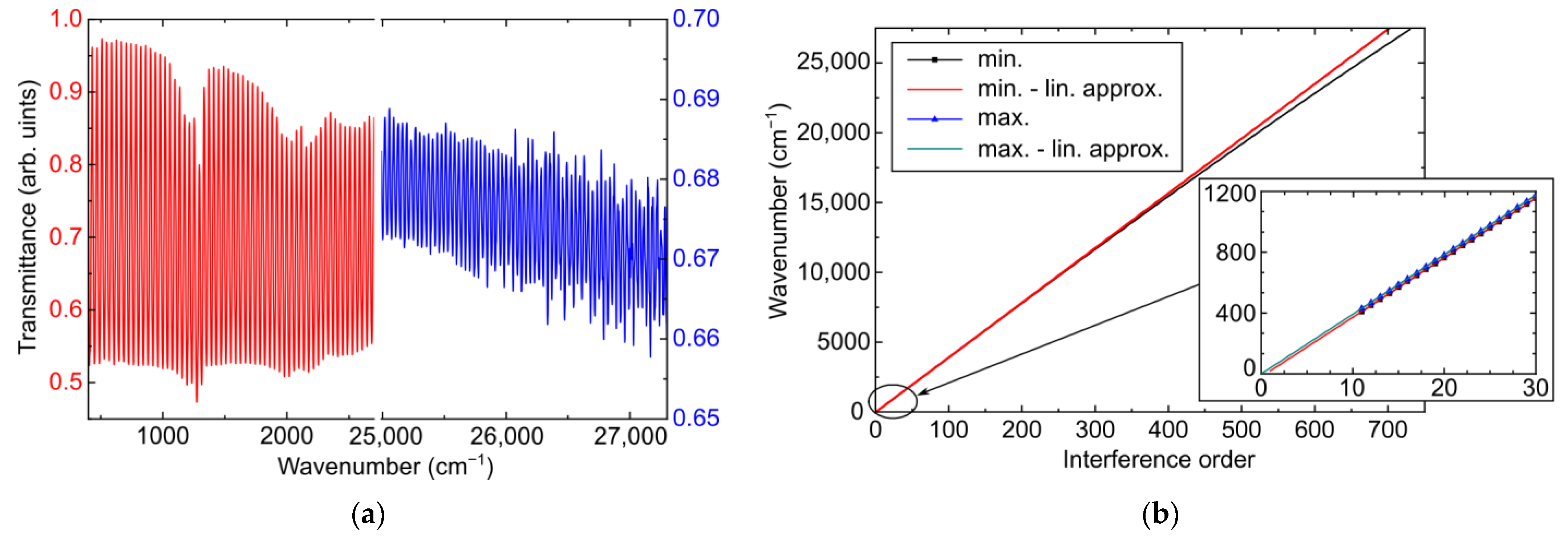
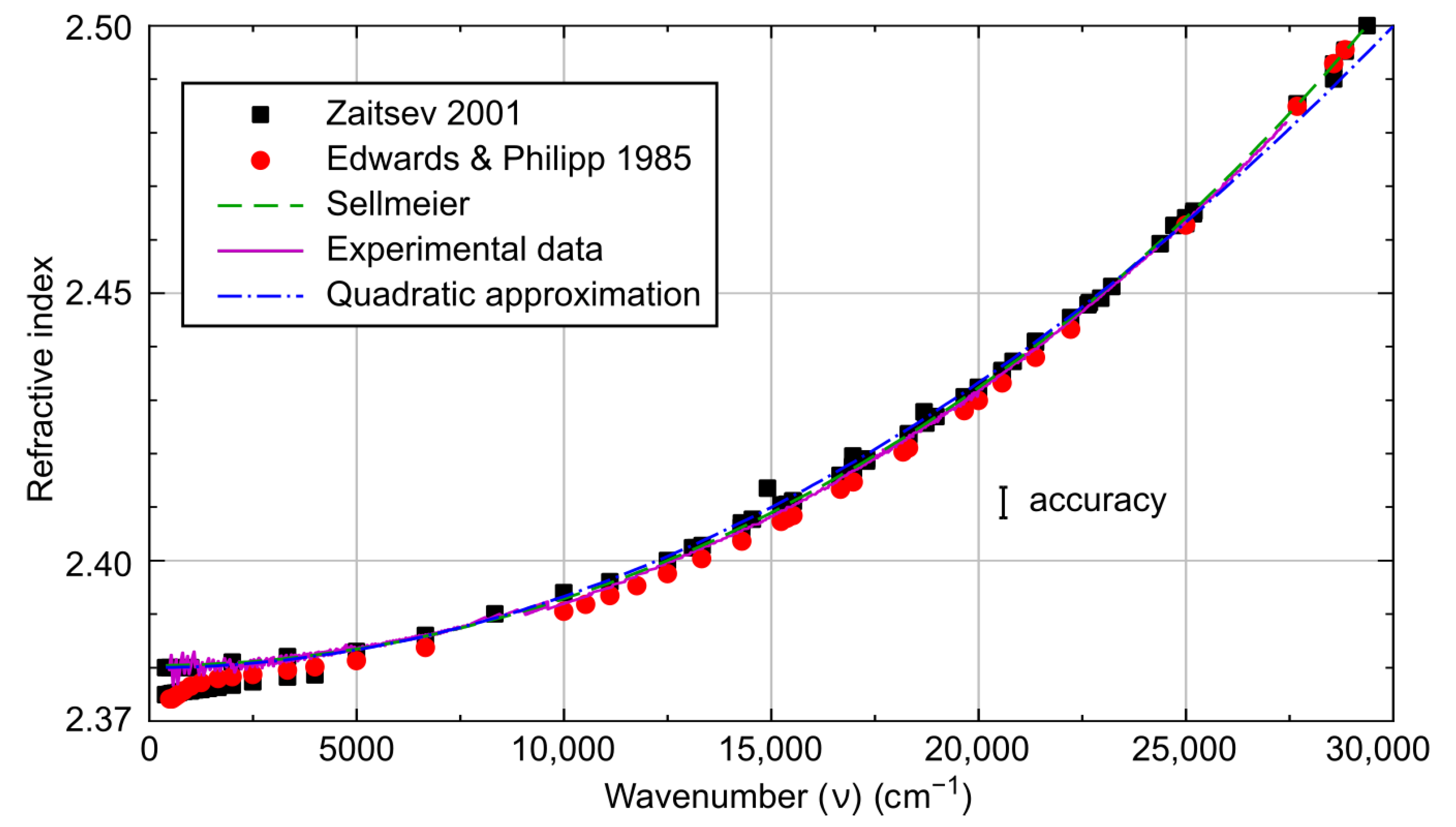
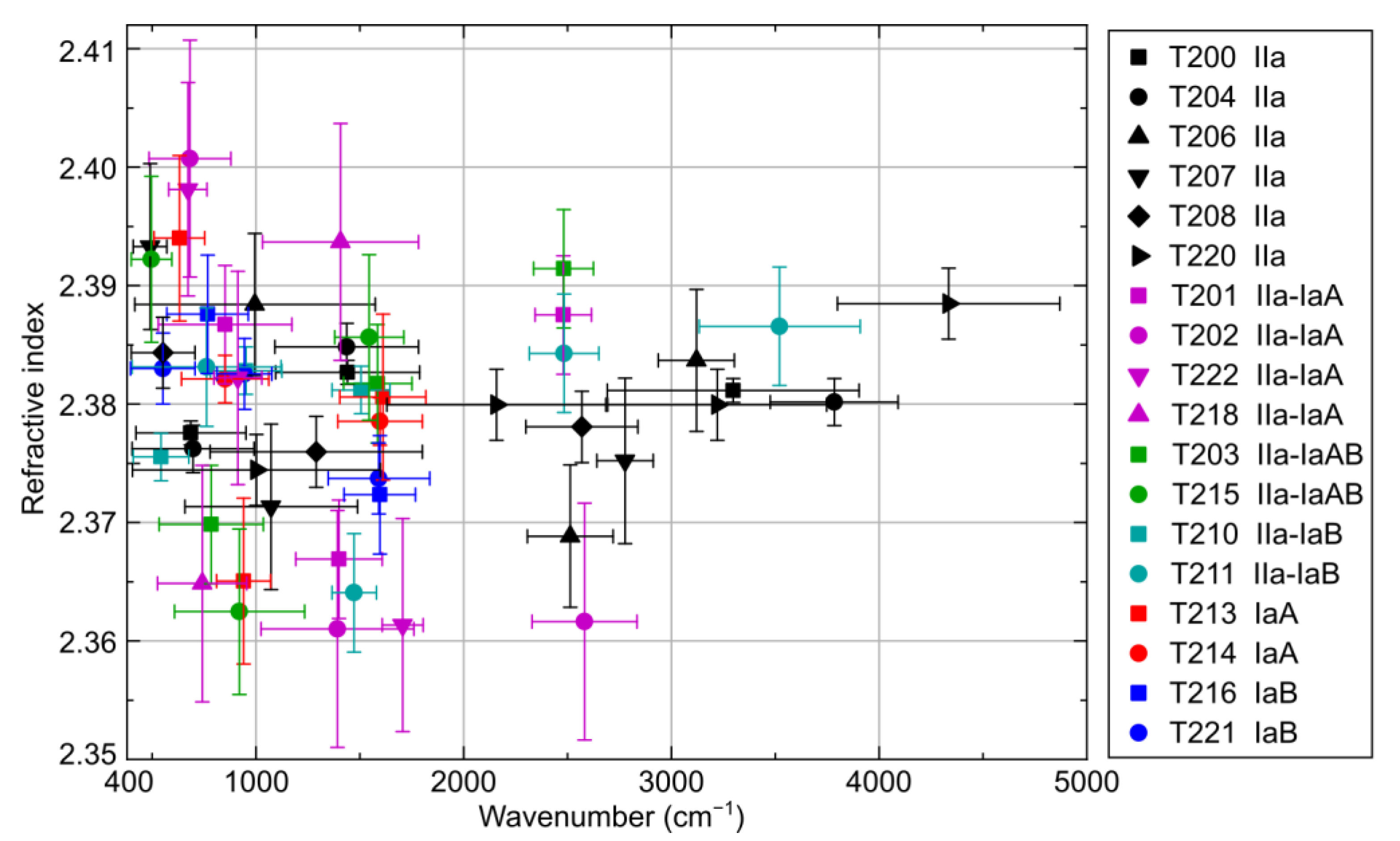
3.1. Interference and Refractive Index of Diamond

Most of the measured FT-IR spectra contain interference components with numerous orders (Fabry–Perot interference for thin plate). As an example, a transmission spectrum of T190 plate with more than 730 interference orders from mid-IR to ultraviolet (UV) range is shown in Figure 1a.
Under normal incidence of light, the optical transmission coefficient is well described by the Airy formula [23,24]:
T = B 1 F cos 4 π n d λ 1 = B 1 F cos 4 π ν n d 10,000 1 ,
where F is the amplitude of the interference component, d is the plate thickness (µm) at the measuring point, n is the refractive index of diamond, λ is the wavelength (µm), ν = 10,000/λ is the wavenumber (cm−1), and B is a slowly varying function of ν, which is determined by reflection, scattering and absorption of light in the plate. The amplitude F also depends on optical reflection and scattering on the surfaces of the plate, the volume absorption, and plane-parallelism of the plate within the measuring aperture.
Figure 1 demonstrates the interference orders starting from the 11th order (minimum at 408.8 cm−1; maximum at 432.0 cm−1). The interference amplitude F decreases with an increase in the interference order, which is mainly caused by non-ideal plane-parallelism and roughness of the plate faces. Nevertheless, extrema of the interference component are clearly distinguishable even in the UV range of the spectrum. As wavenumber increases, the gap between the extrema of the interference signal slightly diminishes due to changes in the optical path length n(ν)d caused by the normal dispersion of the diamond refractive index. These dispersion-related changes can be seen in Figure 1b as a deviation of the experimental dependence of the extrema positions on the order of interference from its linear approximation.
The linear extrapolations of the extrema positions to the range of lower frequencies can be seen in the inset of Figure 1b. It is noteworthy that the estimated position of the zero order maximum is equal to 0 cm−1 with an accuracy better than 2 cm−1. This means that the refractive index is almost constant for the range of wavenumbers from 0 cm−1 to 400 cm−1 (25 µm or 12 THz), the absorption of electromagnetic radiation is negligible, and the square of the refractive index is close to a low-frequency permittivity (2.382 = 5.66).
The interference analysis allows us to calculate the dependence of the optical path length n(ν)d on the wavenumber ν, which is further converted to the dispersion curve n(ν) using the thickness of the plate measured by the indicator gauge with 0.01% accuracy. The estimated dispersion curve corresponding to the spectrum shown in Figure 1 is given in Figure 2 along with data from other sources [22,25] summarizing the results of 15 papers.
According to the dispersion theory, two intensive absorption peaks with maxima at 0.106 µm and 0.175 µm determine the spectral dependency of the diamond refractive index. Figure 2 contains the approximation of this dependency based on the dispersion theory [25] using the Sellmeier formula [22,26]:
n 2 = 1 + 4.3356 · λ 2 λ 2 0.106 2 + 0.3306 λ 2 λ 2 0.175 2 ,
where λ is given in µm. As can be seen from Figure 2, our experimental data are in good agreement with Equation (2). Another option is to use a simple empirical dependence (quadratic approximation)
n = 2.38 1 + 5.6 · 10 11 ν 2 = 2.38 + 0.0133 / λ 2 ,
where ν is in cm−1 and λ is in µm. This approximation provides sufficient accuracy in the range 400–28,000 cm−1 but underestimates the refractive index for wavelengths shorter than 0.36 µm. In the IR range from 400 cm−1 to 4000 cm−1, which is mainly analyzed in this paper, the refractive index changes by less than 0.002 and is equal to 2.380 ± 0.002. The value of 2.38 can also be called a low-frequency refractive index. We should note that different estimates of this value (from 2.37 to 2.387) are given in refs. [18,25,27,28].
The measured transmission spectra for many plates demonstrate beats in the interference amplitude due to the non-plane-parallelism of the plate faces. To illustrate this point, Figure 3 shows the spectra of six diamond plates (samples T203, T206, T210, T214, T221, and T222), as well as the enlarged fragments of the low-frequency range with the most pronounced interference signal. The presence of beats can reduce the accuracy of the calculated optical path length, so we excluded the subranges with considerable beats from further analysis.
For further analysis, we classified the samples according to the characteristic IR features observed in their spectra and used the following color indication for Figure 3 and some subsequent figures. Thus, black color indicates type IIa plates without noticeable characteristic features in the one-phonon range (samples T200, T204, T206, T207, T208, and T220), red is used for IaA type (T213 and T214), and blue corresponds to IaB type (T216 and T221). For the last two types, the optical absorption in the one-phonon range is higher than in the two-phonon range due to high concentration of nitrogen-related defects, and they were distinguished by the position of the transmission minimum corresponding to either A (1282 cm−1 [15]) or B (1175 cm−1 [15]) peak (see the corresponding spectra for IaA and IaB in the upper part of Figure 3). The plates with lower concentrations of these defects (the optical absorption in the one-phonon range is lower than in the two-phonon range) related to IaA type (labeled as IIa-IaA, samples T201, T202, T218, and T222) and IaB type (labeled as IIa-IaB, samples T210 and T211) are shown in the purple and cyan colors, respectively, in the lower part of Figure 3. Two plates (T203 and T215) with slight but distinct differences from IIa type without a predominance of A or B peaks are further referred to as mixed type IIa-IaAB and specified by the green color. Figure 4 presents the refractive indices calculated using the proposed interferometric technique for 18 plates in accordance with the classification and the color indication introduced above. The measurement error shown by vertical bars is mostly determined by the uncertainty of thickness measured using the indicator gauge.
Statistical processing of all measurement results indicates that the refractive index of diamond does not depend on the type and concentration of the main defects within the measurement accuracy of 0.002 in the spectral range 400–5000 cm−1. This conclusion is in agreement with the data given in refs. [22,29]. The experimental result is also supported by an analysis of the contribution of absorption in the IR range to the refractive index using the Kramers–Kronig relations. Our calculations show that even with the largest absorption in the one-phonon region (at the highest encountered nitrogen concentrations of 0.3%) this contribution does not exceed 0.001. In the last century, some studies reported on the dependence of the refractive index of diamond on its impurity-defective composition [25]. It is possible that such an impression arose because of different heating of diamonds of different quality during optical measurements in the IR region. The dependence of the refractive index on temperature is known with sufficient accuracy [28,30]. Since the refractive index with an accuracy of 0.002 does not depend on the concentration of impurities and defects, the dispersion described by formula (2) or the quadratic approximation (3) (see Figure 2) is valid for all diamonds. As a result, we can further use this dispersion curve to estimate the thickness from the positions of extrema in the interference component of the spectra for all samples, which is the main idea of the proposed interferometric technique.

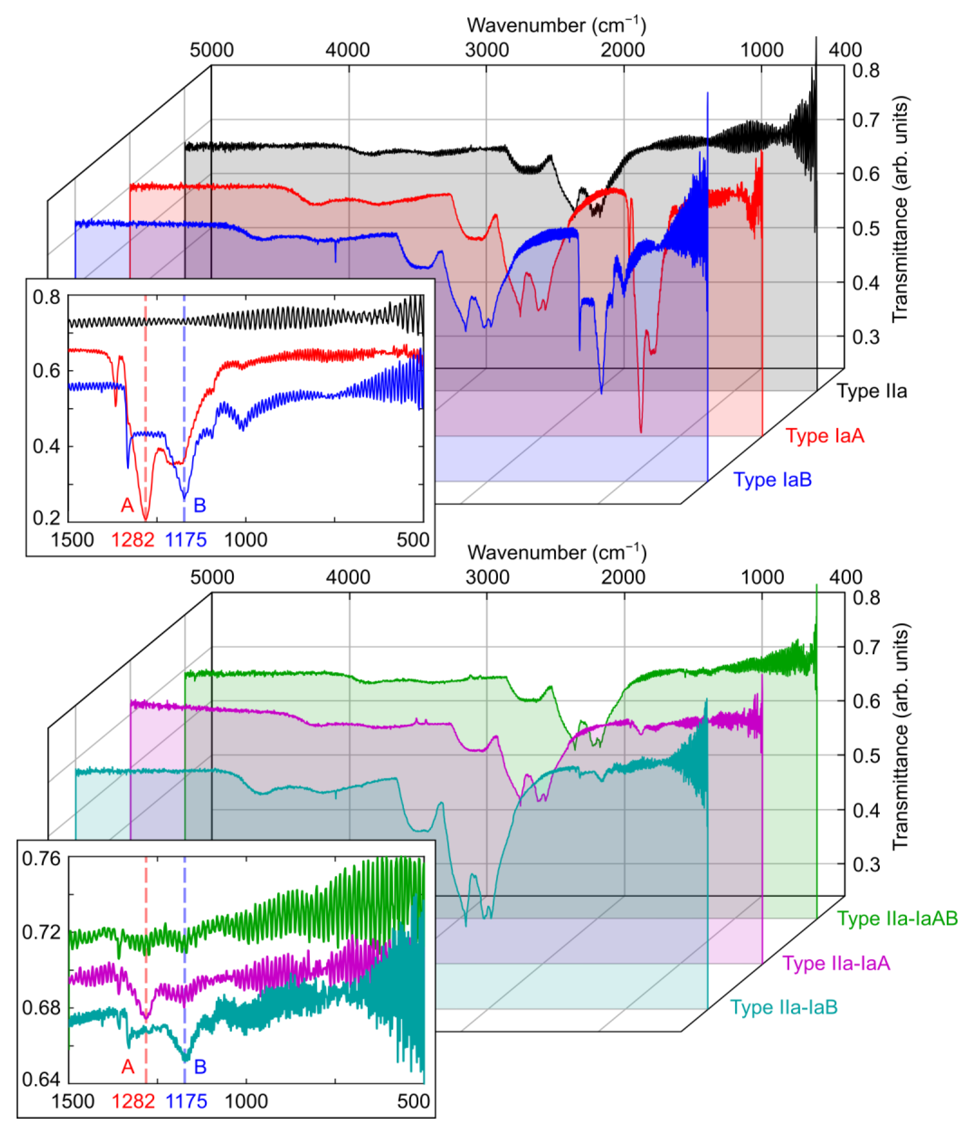
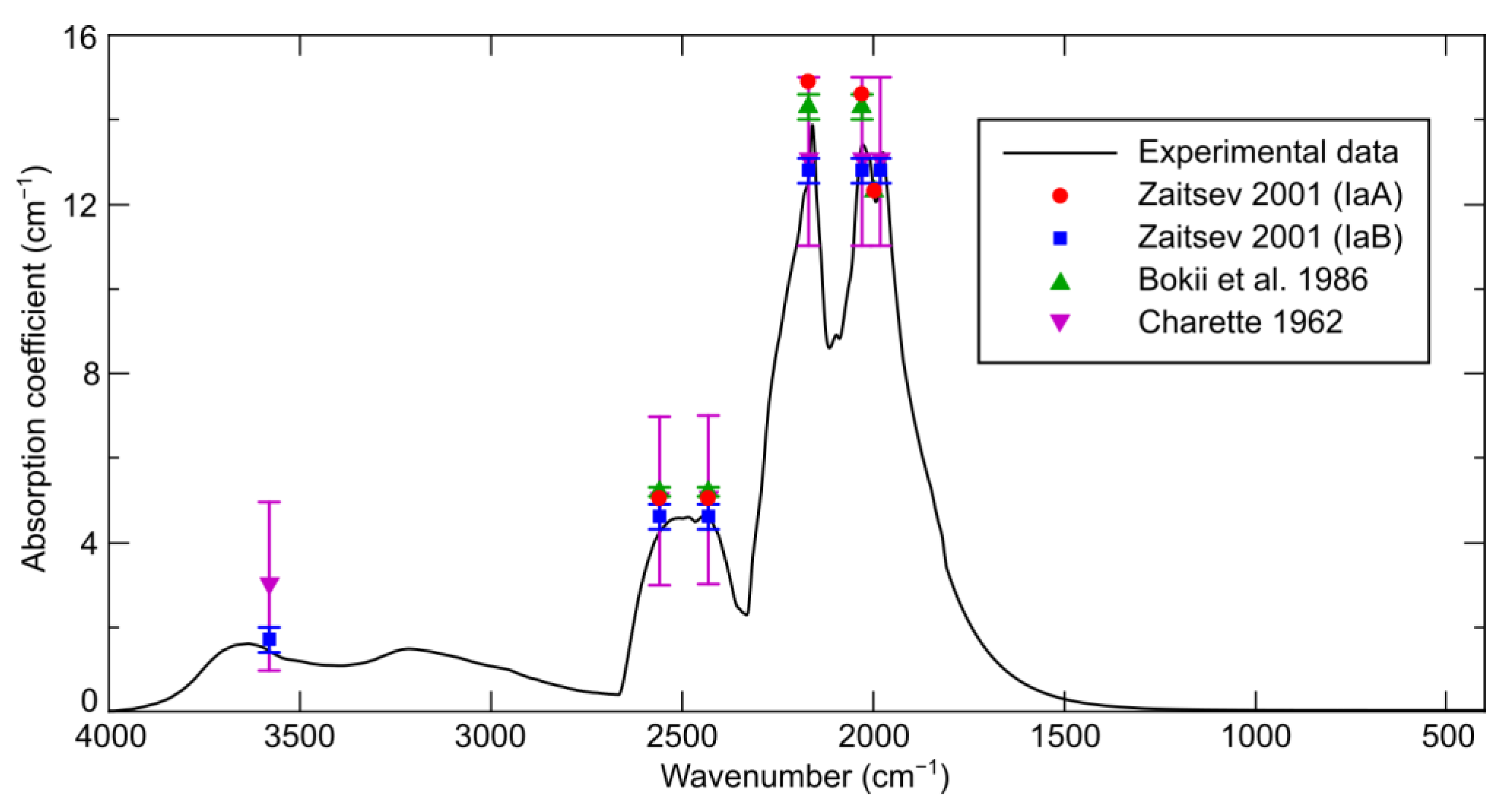
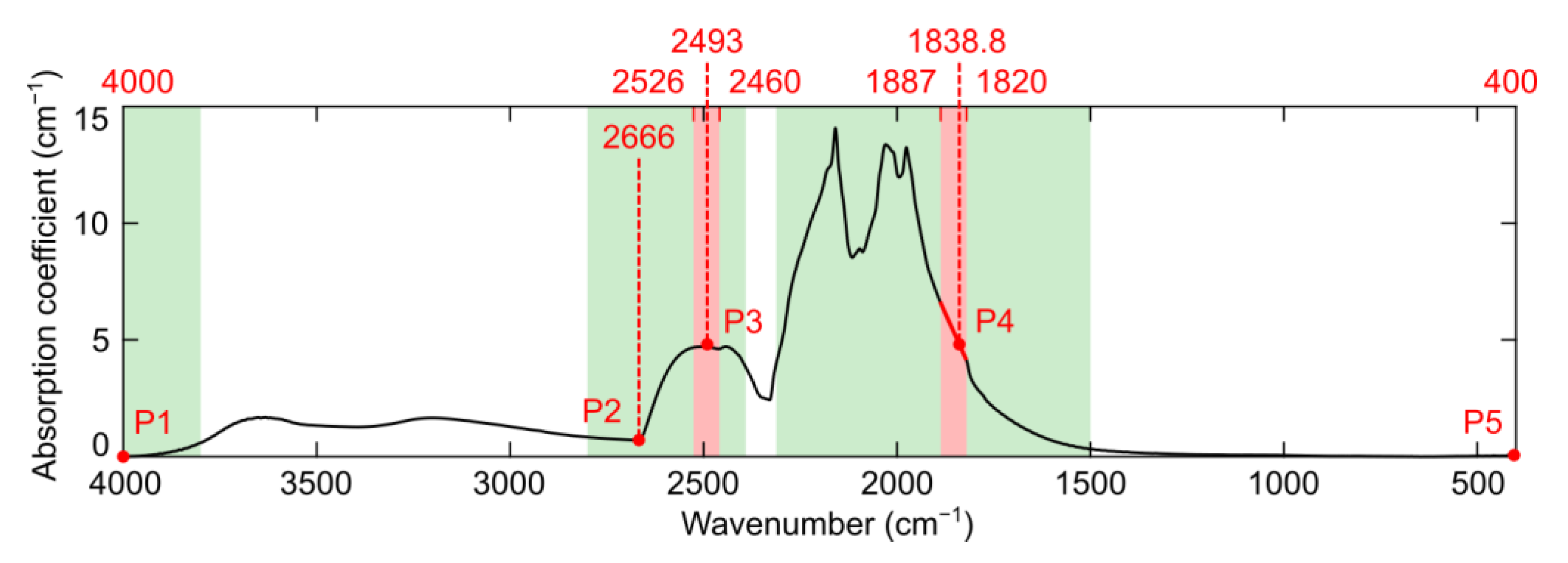
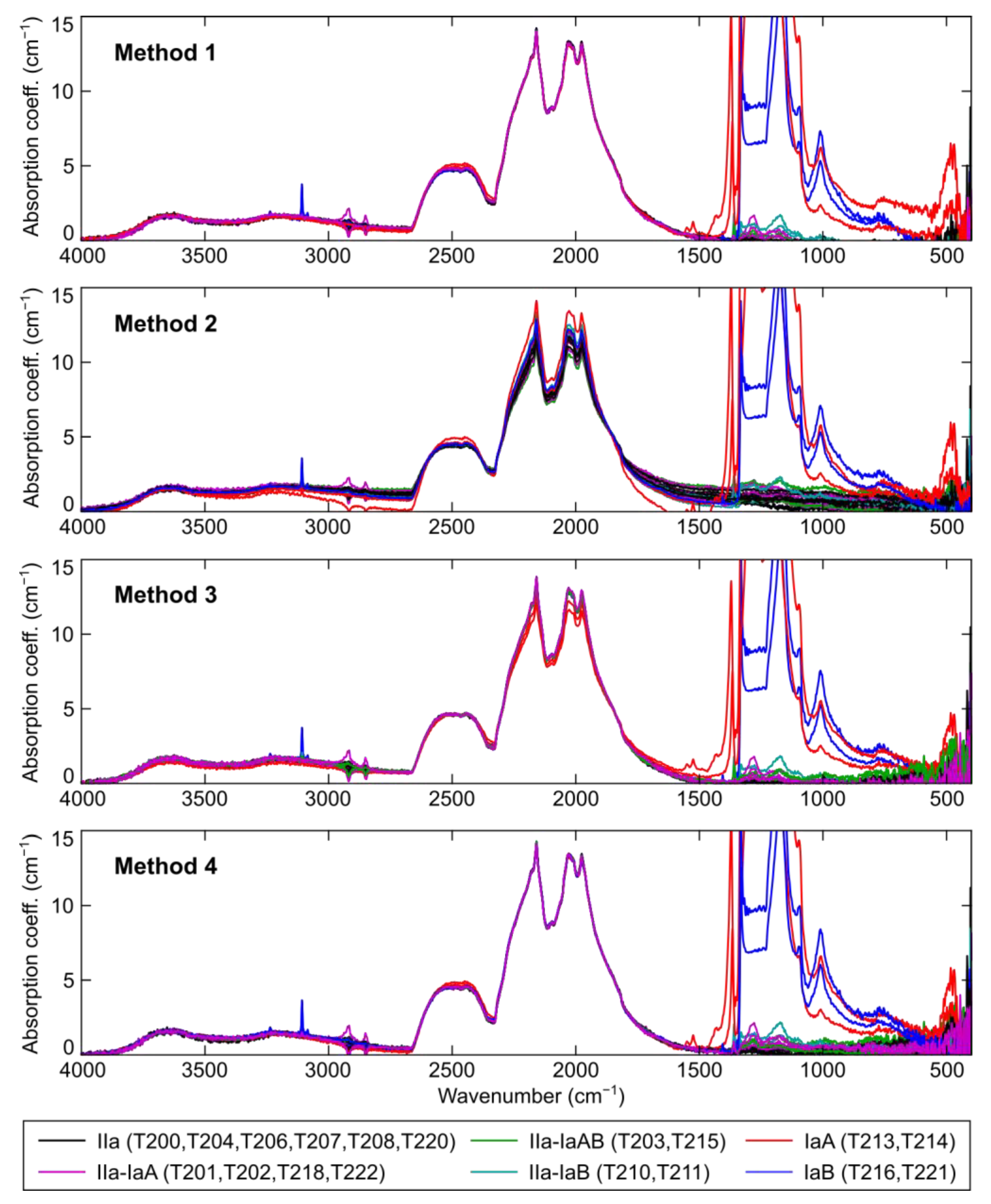
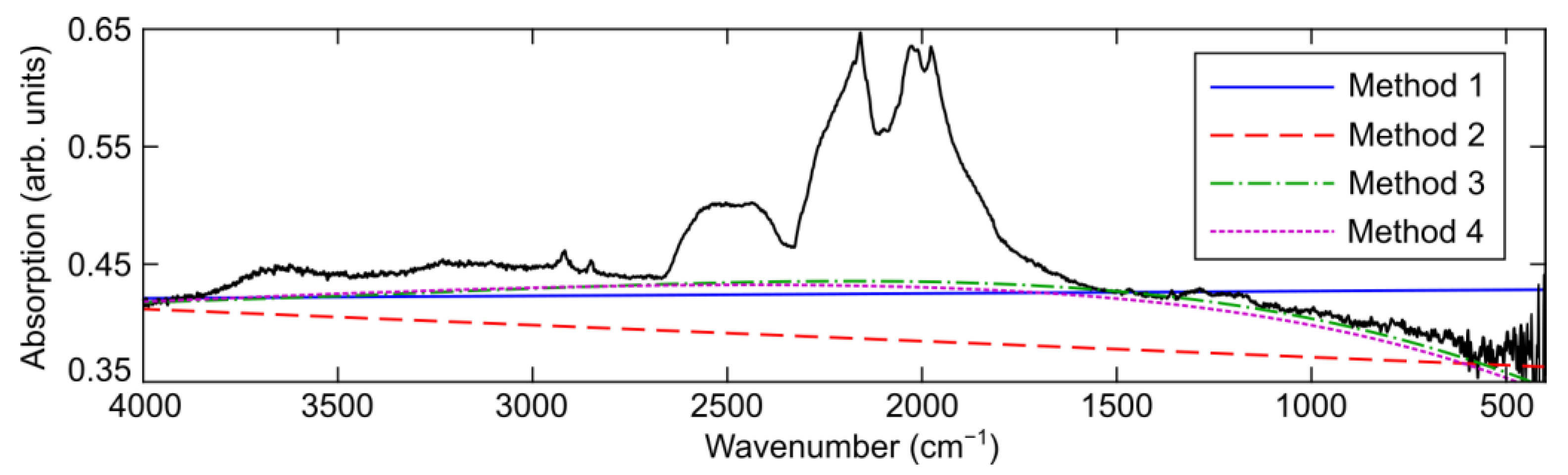
3.2. Intrinsic Diamond Lattice Absorption in IR Range

The values of the absorption coefficient caused by two- and three-phonon intrinsic absorption are used as reference data for baseline correction and simultaneous scaling to 1 cm thickness. Hence, knowing them with high accuracy is crucial for subsequent spectral decomposition and robust determining of nitrogen concentrations. However, these values may vary depending on temperature [28,30] and isotopic composition [31]. In order to obtain an accurate spectral characteristic of intrinsic absorption in the range 400–4000 cm−1, we used measured IR spectra of type IIa samples (T200, T204, T206, T207, T208, and T220) and the corresponding thicknesses estimated using the proposed interferometric technique. The scattering of light, which has a major effect on the slope of the spectrum (the baseline), was significantly reduced in our experiments since we measured absorption of thin polished plates. The acquired average characteristic (the evaluated accuracy is better than ±0.05 cm−1) is listed in Supplementary Materials and demonstrated in Figure 5 as well as data from refs. [22,29,32].
In the range of wavenumbers less than 1400 cm−1, the intrinsic optical absorption of diamond decreases exponentially. According to the results of laser calorimetry, the intrinsic absorption of natural and synthetic low-nitrogen type IIa diamonds does not exceed 0.05 cm−1 at a wavelength of 10.6 µm (943 cm−1) [19,33,34,35].
In contradiction to ref. [31], we did not detect four-phonon absorption; it was not observed even at a temperature of 823 K [29]. Although if we extrapolate the intensity ratio of two- and three-phonon absorption (about 10) to the range above 4000 cm−1, where the four-phonon absorption is expected, the signal-to-noise ratio in our measurements was sufficient to detect four-phonon absorption.
The values of the absorption coefficient at wavenumbers 1990–1995 cm−1, 2030 cm−1 and 2170 cm−1, where maxima are observed (see Figure 5), are typically used as a standard for determining the path length of light [10,22]. Unfortunately, when measuring uncut crystals or crystals with non-parallel faces, the intensity of the transmitted light may drop by two orders of magnitude [14] due to scattering and refraction of light on the crystal surfaces. Therefore, the signal-to-noise ratio of the measured transmission spectra in the subrange 1900–2200 cm−1, where the intrinsic absorption coefficient is higher than 10 cm−1, usually becomes very low if the path length in diamond exceeds 0.3 cm. The sharpness of peaks in this range can potentially lead to a large error in determining their height and location because of limited spectral resolution, sampling period, and noise. In addition, this spectral range includes water absorption peaks, which can significantly affect the result when using non-vacuum IR spectrometers. We suggest using the 2332–2666 cm−1 subrange, which provides the highest signal-to-noise ratio for measurements on most spectrometers. In non-vacuum IR spectrometers, the region 2250–2395 cm−1 accounts for the absorption of CO2, but this does not interfere with measurements in the region 2420–2540 cm−1, where the optical absorption is approximately constant and amounts to 4.5–4.6 cm−1. With this value, the signal is attenuated by a factor of 10 only when the light path is longer than 5 mm.
To correct the baseline and normalize the spectrum, we propose using several points at which the values of the intrinsic absorption coefficient of diamond are known with sufficient accuracy (as shown in Figure 6). We suppose that for ith point (i = 1…N) this reference value μi is related to the value ai of the analyzed spectrum at the same wavenumber νi by the following equation
j = 0 M p j ν i j + μ i d = a i ,
where pj are the polynomial coefficients with maximum degree M, which describe the baseline, and d is the thickness of the sample (the path length). Thus, we can write Equation (4) for each point and calculate the values of pj and d as a solution of the obtained system of N equations. If N = M + 2, one can find the exact solution, and the least squares method can be used for N > M + 2.
We assume that the absorption coefficient μ is equal to zero for the wavenumbers less than 400 cm−1 (point P5) and higher than 4000 cm−1 (point P1). According to the previously obtained characteristic (see Figure 5), the reference value of the absorption coefficient is equal to 0.37 cm−1 at point P2 (2666 cm−1). The values of the analyzed spectrum ai at these points are calculated as the average value in a small neighborhood around the corresponding wavenumbers νi. For point P3 (2493 cm−1), the value a3 is estimated as the average in the range from 2460 cm−1 to 2526 cm−1; this interval is shown in red in Figure 6. In the 1820–1887 cm−1 subrange, the spectrum is approximated by a straight line, and the value a4 for point P4 is defined as the ordinate of the point on this line at 1838.8 cm−1. Reference values for points P3 and P4 are taken equal to 4.6 cm−1.
When five points are used, the maximum degree M of the polynomial in Equation (4) is 3. For comparison, the baseline correction method in ref. [13] uses a non-linear minimization of the squared error to match the reference absorption spectrum and straight baseline in the three ranges highlighted in green in Figure 6 (from 1500 cm−1 to 2312 cm−1, from 2391 cm−1 to 3000 cm−1, and from 3800 cm−1 to 4000 cm−1). In this case, the scale factor (sample thickness) and two baseline coefficients (straight line) act as parameters. The proposed method is faster and does not require iterative minimization. It can be used both independently and as a method for determining the first approximation for subsequent comparison with the reference spectrum in some selected ranges for a given degree of the polynomial.
After the coefficients pj and thickness d have been found, the values of the corrected spectrum as for each wavenumber ν can be calculated as
a s = 1 d a j = 0 M p j ν j .
The normalized spectra for 18 samples, obtained by different methods, are shown in Figure 7. An example of calculated baselines along with the uncorrected spectrum is shown in Figure 8. Method 1 corresponds to ref. [13]. The results for the proposed method with M = 1 (straight baseline) and M = 3 are labeled as Method 2 and 3, respectively. Method 4 also uses Equation (4) but takes all values ai and μi of the analyzed spectrum and the reference spectrum (Figure 5), respectively, in the three ranges highlighted in green in Figure 6 and also at the 400 cm−1 point. As a result, a system with a large number N is obtained, and its solution is found using the least squares method for the maximum degree M equal to 3 or more (the demonstrated example uses M = 5). As can be seen from Figure 8, the processed spectra have a noticeable bend of the baseline for wavenumbers lower than 1400 cm−1, which hampers the use of methods with a straight baseline (Methods 1 and 2). Thus, Methods 3 and 4 are preferable for obtaining adequate results using the spectral decomposition in the one-phonon range afterwards.
The thicknesses estimated using all methods as well as the thicknesses dm measured using the indicator gauge are presented in Table 1 for 18 samples. The error values (d − dm) are listed in each column for Methods 1–4. In the rightmost column (‘Interf.’), the difference (dint − dm) is provided, where dint is the thickness estimated using the proposed interferometric technique in the range 410–4000 cm−1 and the refractive index defined by Equation (3). All methods, except for Method 2, provide an error in estimating the plate thickness (path length) of less than 10%. Deviations from the indicator gauge measurements for Methods 1 and 4 are comparable to the discrepancies between the results of the interferometric method and the indicator.

4. Conclusions

In this study, we proposed an interferometric method for determining the optical path length in thin plane-parallel diamond plates and applied it to measure the refractive index of various natural diamond samples. The results allowed us to obtain a robust estimate of thickness for each sample and get an accurate spectral characteristic of intrinsic absorption in the mid-IR range by averaging the data for IIa-type diamond samples. Using the acquired characteristic and its five stable reference points, the accurate general iterative procedure of the baseline correction and scaling of mid-IR diamond spectra was developed. The proposed techniques were demonstrated to enable more precise measurements of diamond thicknesses for diverse weakly and strongly absorbing natural diamonds and pave a way to precise measurements of weak mid-IR absorption of ultralow impurity concentrations.

Supplementary Materials

The following supporting information can be downloaded at: https://www.mdpi.com/article/10.3390/chemosensors11060313/s1. Table S1: Standard of spectral characteristic of intrinsic diamond absorption.

Author Contributions

Conceptualization, R.K., O.K. and S.K.; methodology, R.K. and O.K.; software, A.G.; validation, R.K., S.K. and O.K.; formal analysis, A.G., D.P. and P.D.; investigation, R.K., O.K., A.G. and D.P.; resources, R.K.; data curation, R.K. and A.G.; writing—original draft preparation, A.G., D.P. and P.D.; writing—review and editing, S.K., P.D. and R.K.; visualization, A.G., R.K. and D.P.; supervision, S.K.; project administration, S.K.; funding acquisition, S.K. All authors have read and agreed to the published version of the manuscript.

Funding

Russian Science Foundation, project #21-79-30063, https://rscf.ru/en/project/21-79-30063/ (accessed on 30 March 2023).

Institutional Review Board Statement

Not applicable.

Informed Consent Statement

Not applicable.

Data Availability Statement

The data supporting the reported results are available from the authors upon reasonable request.

Conflicts of Interest

The authors declare no conflict of interest.

References

  1. Ashfold, M.N.R.; Goss, J.P.; Green, B.L.; May, P.W.; Newton, M.E.; Peaker, C.V. Nitrogen in diamond. Chem. Rev. 2020, 120, 5745–5794. [Google Scholar] [CrossRef] [PubMed]
  2. Walker, J. Optical absorption and luminescence in diamond. Rep. Prog. Phys. 1979, 42, 1605–1659. [Google Scholar] [CrossRef]
  3. Green, B.L.; Collins, A.T.; Breeding, C.M. Diamond spectroscopy, defect centers, color, and treatments. Rev. Mineral. Geochem. 2022, 88, 637–688. [Google Scholar] [CrossRef]
  4. Kupriyanov, I.N.; Palyanov, Y.N.; Kalinin, A.A.; Shatsky, V.S. Effect of HPHT treatment on spectroscopic features of natural type Ib-IaA diamonds containing Y centers. Crystals 2020, 10, 378. [Google Scholar] [CrossRef]
  5. Wu, G.C.; Yu, X.Y.; Liu, F.; Li, H.B.; Long, Z.Y.; Wang, H. Color genesis of brown diamond from the Mengyin kimberlite, China. Crystals 2022, 12, 449. [Google Scholar] [CrossRef]
  6. Laidlaw, F.H.J.; Diggle, P.L.; Breeze, B.G.; Dale, M.W.; Fisher, D.; Beanland, R. Spatial distribution of defects in a plastically deformed natural brown diamond. Diam. Relat. Mater. 2021, 117, 108465. [Google Scholar] [CrossRef]
  7. Yuryeva, O.P.; Rakhmanova, M.I.; Zedgenizov, D.A.; Kalinina, V.V. Spectroscopic evidence of the origin of brown and pink diamonds family from Internatsionalnaya kimberlite pipe (Siberian craton). Phys. Chem. Miner. 2020, 47, 1–19. [Google Scholar] [CrossRef]
  8. Kudryashov, S.I.; Vins, V.G.; Danilov, P.A.; Kuzmin, E.V.; Muratov, A.V.; Kriulina, G.Y.; Levchenko, A.O. Permanent optical bleaching in HPHT-diamond via aggregation of C-and NV-centers excited by visible-range femtosecond laser pulses. Carbon 2023, 201, 399–407. [Google Scholar] [CrossRef]
  9. Lawson, S.C.; Fisher, D.; Hunt, D.C.; Newton, M.E. On the existence of positively charged single-substitutional nitrogen in diamond. J. Phys. Condens. Matter 1998, 10, 6171–6180. [Google Scholar] [CrossRef]
  10. Howell, D.; O’Neill, C.J.; Grant, K.J.; Griffin, W.L.; Pearson, N.J.; O’Reilly, S.Y. μ-FTIR mapping: Distribution of impurities in different types of diamond growth. Diam. Relat. Mater. 2012, 29, 29–36. [Google Scholar] [CrossRef]
  11. Babich, Y.V.; Babich, I.Y. Batch processing of diamond IR spectra for mineralogical-geochemical research. Geochem. Int. 2012, 50, 711–717. [Google Scholar] [CrossRef]
  12. Spetsius, Z.V.; Bogush, I.N.; Kovalchuk, O.E. FTIR mapping of diamond plates of eclogitic and peridotitic xenoliths from the Nyurbinskaya pipe, Yakutia: Genetic implications. Russ. Geol. Geophys. 2015, 56, 344–353. [Google Scholar] [CrossRef]
  13. Speich, L.; Kohn, S.C. QUIDDIT—QUantification of infrared active Defects in Diamond and Inferred Temperatures. Comput. Geosci. 2020, 144, 104558. [Google Scholar] [CrossRef]
  14. Khmelnitsky, R.A.; Kovalchuk, O.E.; Gulina, Y.S.; Nastulyavichus, A.A.; Kriulina, G.Y.; Boldyrev, N.Y.; Kudryashov, S.I.; Levchenko, A.O.; Shiryaev, V.S. Optimal direction and propagation of mid-IR light inside rough and polished diamonds for highly-sensitive transmission measurements of nitrogen content. Diam. Relat. Mater. 2022, 128, 109278. [Google Scholar] [CrossRef]
  15. Smith, S.D.; Hardy, J.R. Activation of single phonon infra-red lattice absorption in neutron irradiated diamond. Philos. Mag. 1960, 5, 1311–1314. [Google Scholar] [CrossRef]
  16. Kudryashov, S.I.; Rimskaya, E.N.; Kuzmin, E.V.; Kriulina, G.Y.; Pryakhina, V.I.; Muratov, A.V.; Khmelnitskii, R.A.; Greshnyakov, E.D.; Danilov, P.A.; Shur, V.Y. Advanced Mapping of Optically-Blind and Optically-Active Nitrogen Chemical Impurities in Natural Diamonds. Chemosensors 2023, 11, 24. [Google Scholar] [CrossRef]
  17. Wehner, R.; Borik, H.; Kress, W.; Goodwin, A.; Smith, S. Lattice dynamics and infra-red absorption of diamond. Solid State Commun. 1967, 5, 307–309. [Google Scholar] [CrossRef]
  18. Clement, R.E. LWIR spectral properties of CVD diamond at cryogenic temperatures. Diam. Relat. Mater. 1997, 6, 169–171. [Google Scholar] [CrossRef]
  19. Mollart, T.P.; Lewis, K.L.; Pickles, C.S.J.; Wort, C.J.H. Factors affecting the optical performance of CVD diamond infrared optics. Semicond. Sci. Technol. 2003, 18, S117. [Google Scholar] [CrossRef]
  20. Koidl, P.; Klages, C.P. Optical applications of polycrystalline diamond. Diam. Relat. Mater. 1992, 1, 1065–1074. [Google Scholar] [CrossRef]
  21. Hardy, J.R.; Smith, S.D. Two-phonon infra-red lattice absorption in diamond. Philos. Mag. 1961, 6, 1163–1172. [Google Scholar] [CrossRef]
  22. Zaitsev, A.M. Optical Properties of Diamond. Data Handbook; Springer: Berlin/Heidelberg, Germany, 2001. [Google Scholar] [CrossRef]
  23. Soler, F.J.P. Multiple reflections in an approximately parallel plate. Opt. Commun. 1997, 139, 165–169. [Google Scholar] [CrossRef]
  24. Ruf, T.; Cardona, M.; Pickles, C.S.J.; Sussmann, R. Temperature dependence of the refractive index of diamond up to 925 K. Phys. Rev. B 2000, 62, 16578–16581. [Google Scholar] [CrossRef]
  25. Edwards, D.; Philipp, H.R. Cubic carbon (diamond). In Handbook of Optical Constants of Solids; Palik, E.D., Ed.; Academic Press: Orlando, FL, USA, 1985; pp. 665–673. [Google Scholar] [CrossRef]
  26. Collins, A.T. Intrinsic and extrinsic absorption and luminescence in diamond. Physica B 1993, 185, 284. [Google Scholar] [CrossRef]
  27. Edwards, D.; Ochoa, E. Infrared refractive index of diamond. J. Opt. Soc. Am. 1981, 71, 607–608. [Google Scholar] [CrossRef]
  28. Fontanella, J.; Johnston, R.L.; Colwell, J.H.; Andeen, C. Temperature and pressure variation of the refractive index of diamond. Appl. Opt. 1977, 16, 2949–2951. [Google Scholar] [CrossRef]
  29. Bokii, G.B.; Bezrukov, G.N.; Klyuev, Y.A.; Naletov, A.M.; Nepsha, V.I. Natural and Synthetic Diamonds; Nauka: Moscow, Russia, 1986. [Google Scholar]
  30. Piccirillo, C.; Davies, G.; Mainwood, A.; Scarle, S.; Penchina, C.M.; Mollart, T.P.; Lewis, K.L.; Nesládek, M.; Remes, Z.; Pickles, C.S.J. Temperature dependence of intrinsic infrared absorption in natural and chemical-vapor deposited diamond. J. Appl. Phys. 2002, 92, 756–763. [Google Scholar] [CrossRef]
  31. Vogelgesang, R.; Alvarenga, A.D.; Hyunjung, K.; Ramdas, A.K.; Rodriguez, S.; Grimsditch, M.; Anthony, T.R. Multiphonon Raman and infrared spectra of isotopically controlled diamond. Phys. Rev. B 1998, 58, 5408–5416. [Google Scholar] [CrossRef]
  32. Charette, J.J. Absorption spectra of type I and type II synthetic diamonds. J. Chem. Phys. 1962, 37, 3014. [Google Scholar] [CrossRef]
  33. Harris, D. Properties of diamond for window and dome applications. Proc. SPIE 1994, 2286, 218–228. [Google Scholar] [CrossRef]
  34. Thomas, M. Multiphonon model for absorption in diamond. Proc. SPIE 1994, 2286, 152–159. [Google Scholar] [CrossRef]
  35. Sussmann, R.S.; Pickles, C.S.J.; Brandon, J.R.; Wort, C.J.H.; Coe, S.E.; Wasenczuk, A.; Dodge, C.N.; Beale, A.C.; Krehan, A.J.; Dore, P.; et al. CVD diamond windows for infrared synchrotron applications. Nuovo Cim. D 1998, 20, 503–525. [Google Scholar] [CrossRef]
Figure 1. Characterization of interference signal in FT-IR transmission spectrum of plane-parallel diamond plate: (a) Two parts of measured spectrum with a gap between 2700 cm−1 and 25,000 cm−1; left (red color) and right (blue) parts of the spectrum correspond to left and right vertical axes; (b) Positions of minima (min.) and maxima (max.) of interference signal depending on interference order and linear approximations (lin. approx.) of these dependencies. The inset shows an enlarged part of the plot.
Chemosensors 11 00313 g001
Figure 2. Refractive index of diamond: experimental data (purple solid line; accuracy is shown by vertical bar), approximation using Sellmeier formula (green dashed line), quadratic approximation (blue dash-dotted line), and data from other sources (black squares and red circles are used for data from refs. [22,25], respectively).
Chemosensors 11 00313 g002
Figure 3. FT-IR transmission spectra of plates cut from natural diamonds of different types (upper part: IIa (sample T206), black line; IaA (T214), red; IaB (T221), blue; lower part: IIa-IaAB (T203), green line; IIa-IaA (T222), purple line; IIa-IaB (T210), cyan line). The insets show the enlarged view of the spectra in the range 500–1500 cm−1 and the positions of peaks corresponding to A and B centers (spectral assignment after [22]); the spectra in the insets are shifted along the vertical axis for clarity.
Chemosensors 11 00313 g003
Figure 4. Refractive index of 18 diamond plates (sample numbers and types are specified by shape and color of symbols according to the legend in the right part) calculated using the interferometric method in various subranges of IR spectrum. Vertical bars represent measurement errors; horizontal bars indicate the subranges of spectra used for calculations.
Chemosensors 11 00313 g004
Figure 5. Experimentally acquired spectral characteristic of intrinsic diamond absorption (black line, with an uncertainty of ±0.05 cm−1) and absorption coefficients values at individual wavenumbers (data from refs. [22,29,32], colored symbols, uncertainty is indicated by vertical bar if known).
Chemosensors 11 00313 g005
Figure 6. Specification of points (P1–P5) used for baseline correction and scaling of absorption spectra: reference spectrum (black line), points and subranges used for their localization (red color), and ranges used in the method from ref. [13] (for comparison, green color).
Chemosensors 11 00313 g006
Figure 7. Absorption spectra of 18 samples (see the legend in the bottom part for sample numbers and types of diamonds) after baseline correction and normalization: method from ref. [13] (Method 1); proposed method with M = 1 (Method 2); proposed method with M = 3 (Method 3); method using the same ranges as Method 1 with added point at 400 cm−1 and M = 5 (Method 4).
Chemosensors 11 00313 g007
Figure 8. Uncorrected absorption spectrum (black solid line) and baselines obtained by various methods (colored lines, see the notation in the right part) for sample T206.
Chemosensors 11 00313 g008
Table 1. Measured and estimated thickness of samples.
Sample
Number
Sample
Type
Thickness,
µm
Error, µm
Method 1Method 2Method 3Method 4Interf. *
T200IIa216.20.951.1−16.3−4.8−1.6
T201IIa-IaA211.3−0.847.2−16.2−6.4−3.1
T202IIa-IaA168.4−1.955.7−16.4−6.7−6.2
T203IIa-IaAB166.8−0.964.7−14.7−6.7−7.3
T204IIa220.8−2.263.0−18.6−8.2−6.1
T206IIa150.22.934.3−9.7−1.7−1.7
T207IIa314.4−1.953.4−23.3−9.9−6.9
T208IIa192.43.129.5−10.9−1.4−0.8
T210IIa-IaB395.4−1.022.1−24.7−10.1−2.8
T211IIa-IaB259.71.944.7−15.7−4.9−2.7
T213IaA281.78.3−15.526.7−1.9−0.4
T214IaA295.31.329.80.6−7.9−5.1
T215IIa-IaAB331.54.537.0−15.8−3.32.8
T216IaB412.32.653.220.5−7.7−0.4
T218IIa-IaA205.67.434.5−8.20.30.1
T220IIa201.32.227.6−11.4−4.0−2.0
T221IaB218.73.549.5−11.4−3.4−2.8
T222IIa-IaA184.8−1.330.2−15.2−7.3−1.8
Mean--1.639.6−10.0−5.3−2.7
Standard dev.--3.018.713.53.02.7
* The proposed interferometric technique.
Disclaimer/Publisher’s Note: The statements, opinions and data contained in all publications are solely those of the individual author(s) and contributor(s) and not of MDPI and/or the editor(s). MDPI and/or the editor(s) disclaim responsibility for any injury to people or property resulting from any ideas, methods, instructions or products referred to in the content.

