
Convective Heat Transfer and Entropy Generation for Nano-Jet Impingement Cooling of a Moving Hot Surface under the Effects of Multiple Rotating Cylinders and Magnetic Field
 , , ,
, , ,  and
and 
Abstract
:1. Introduction
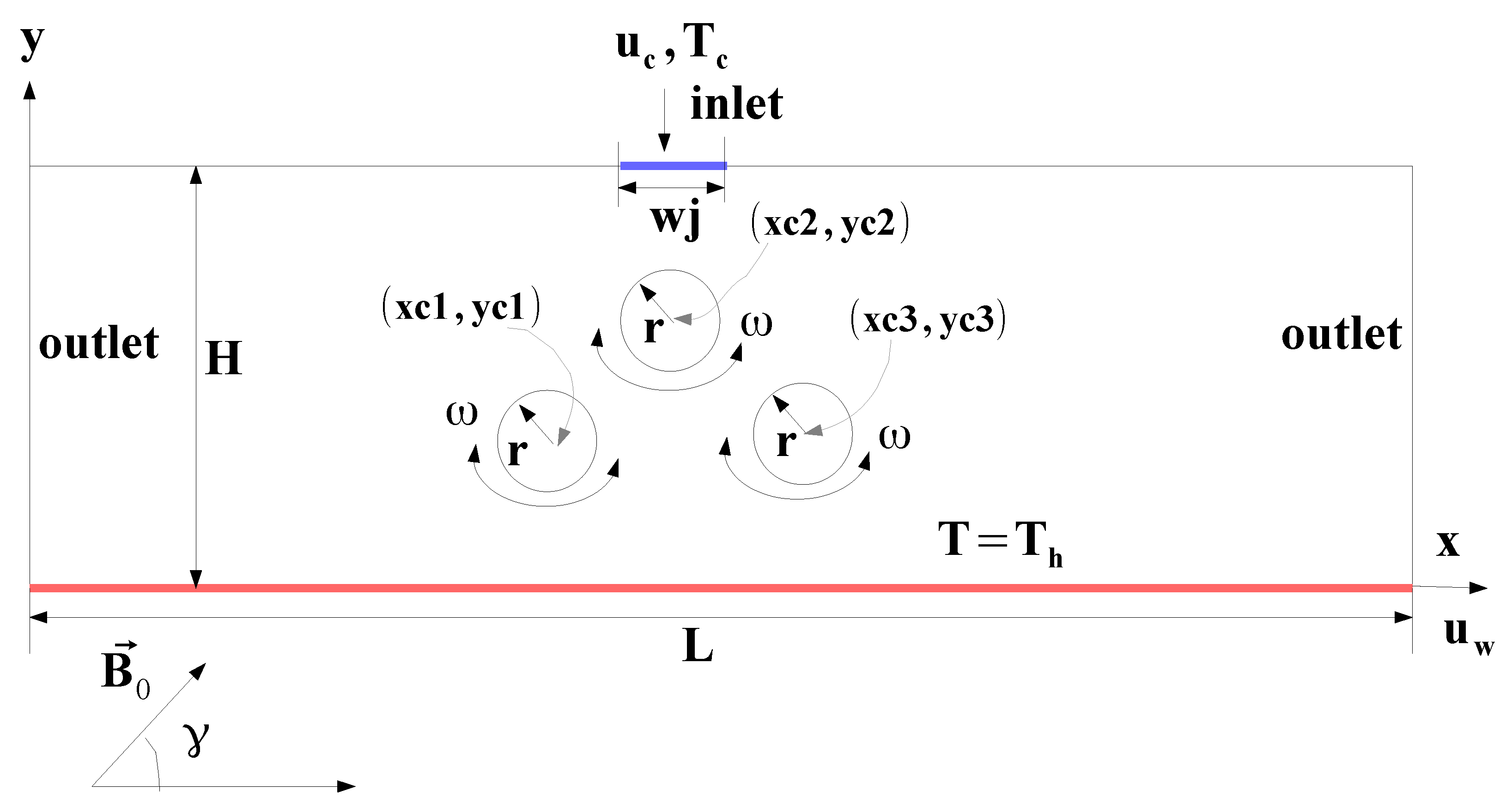
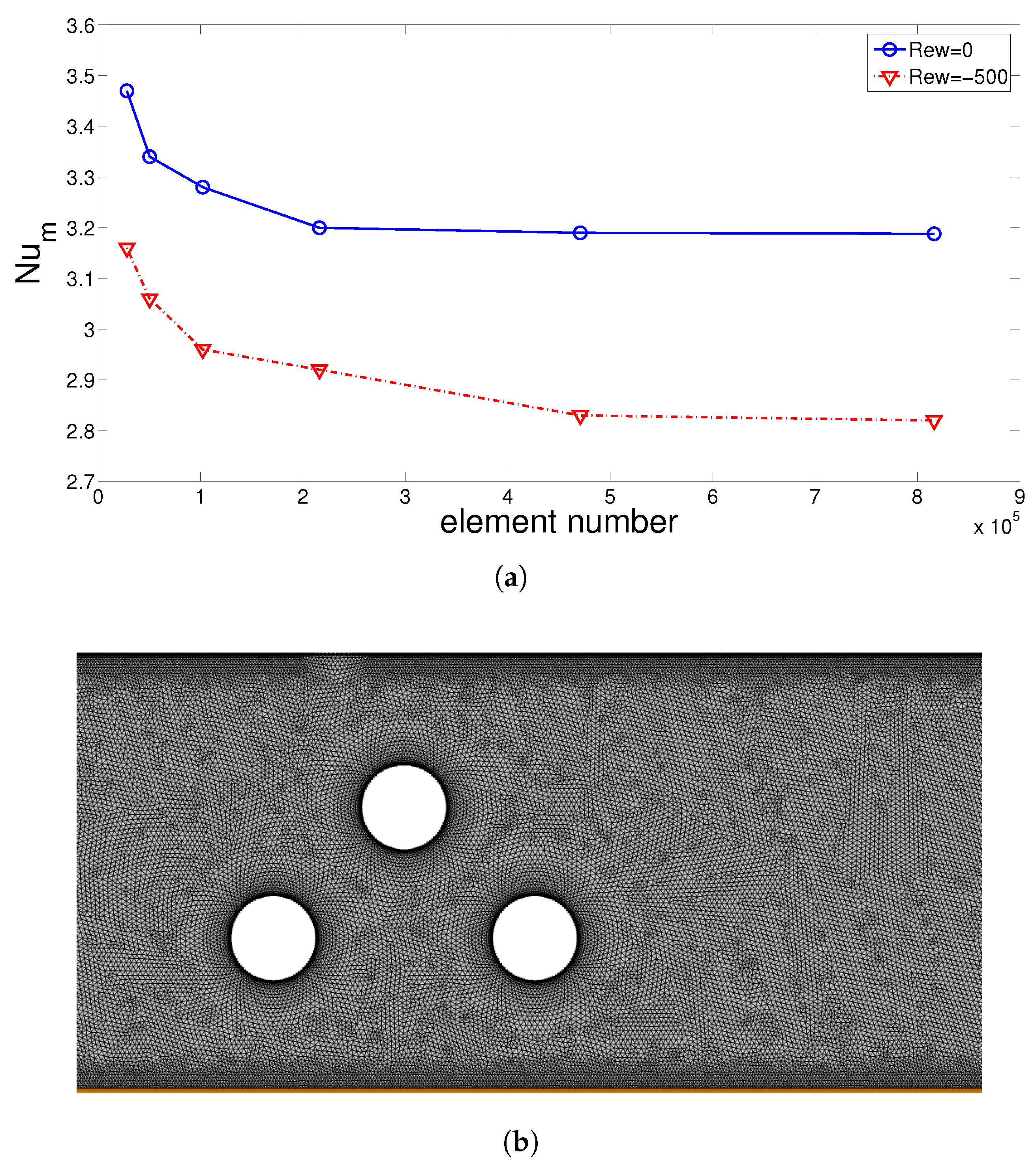
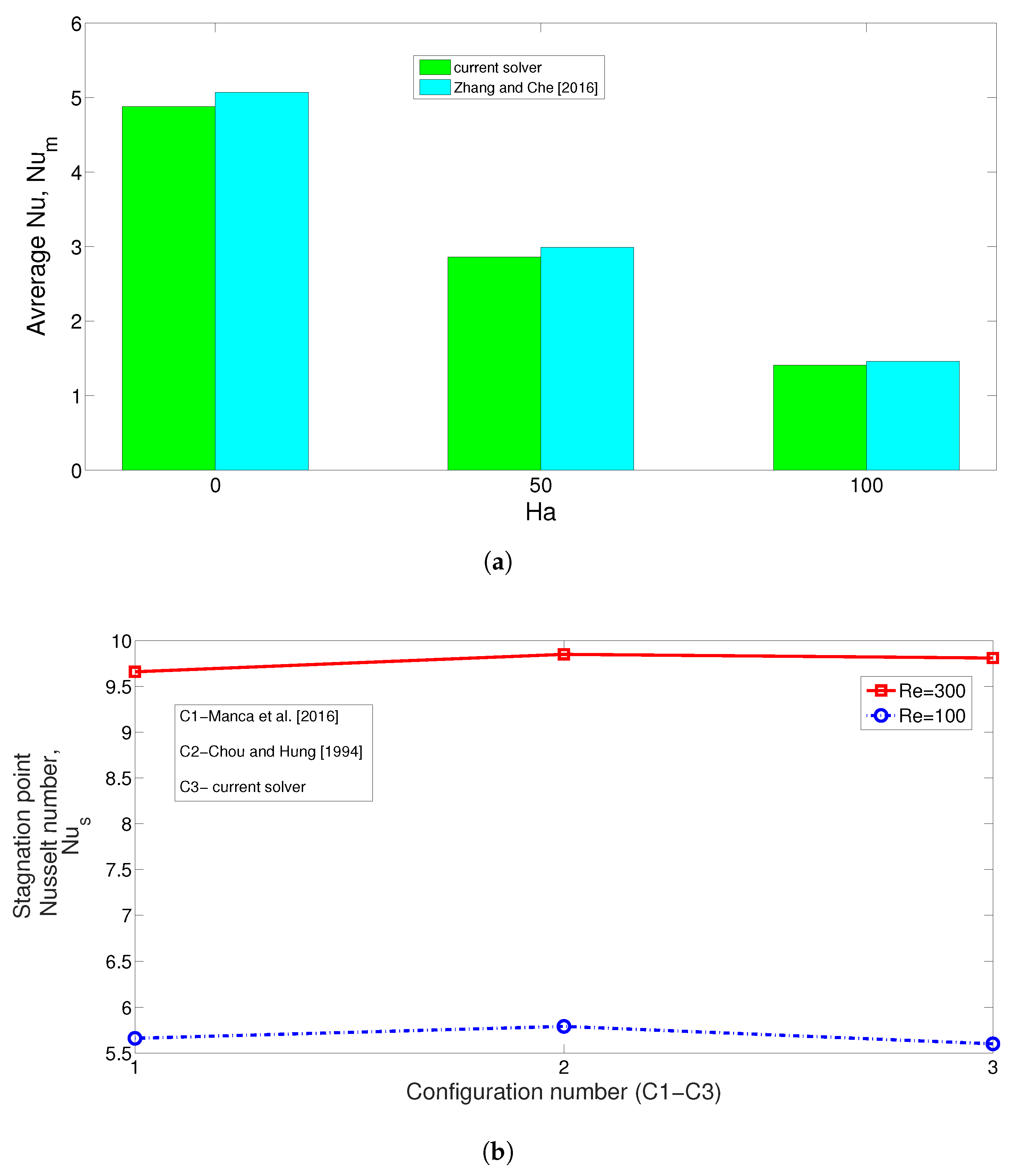
2. Numerical Model
- Jet inlet,
- Outlet:
- At the target plate:
- Upper plate walls:
- At the rotating cylinder walls:
3. Results and Discussion
4. Conclusions
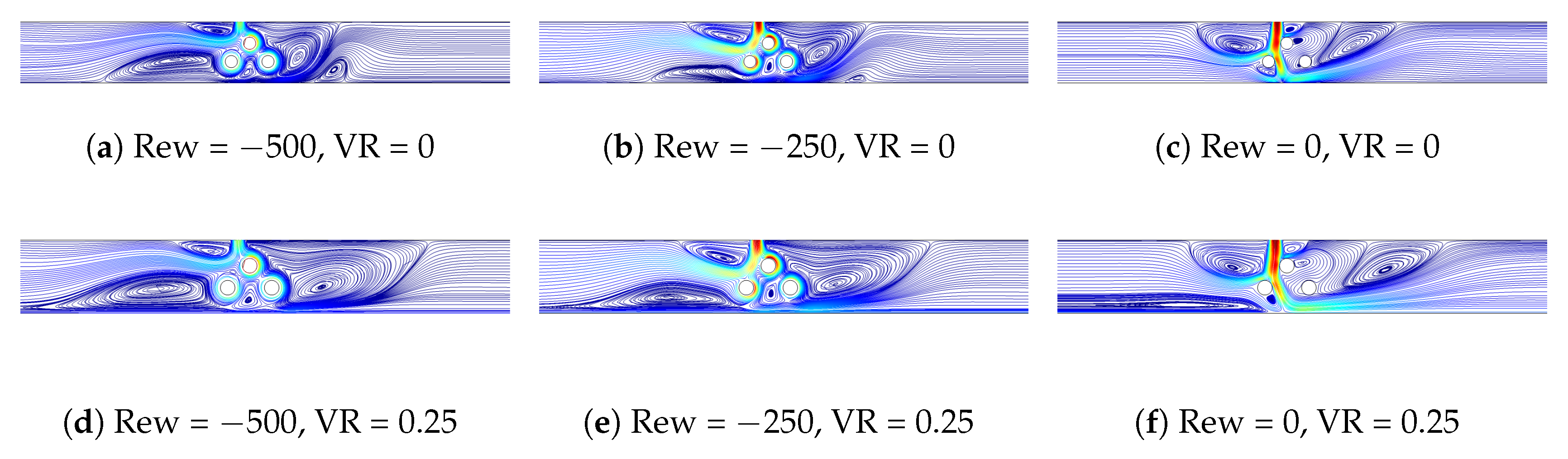
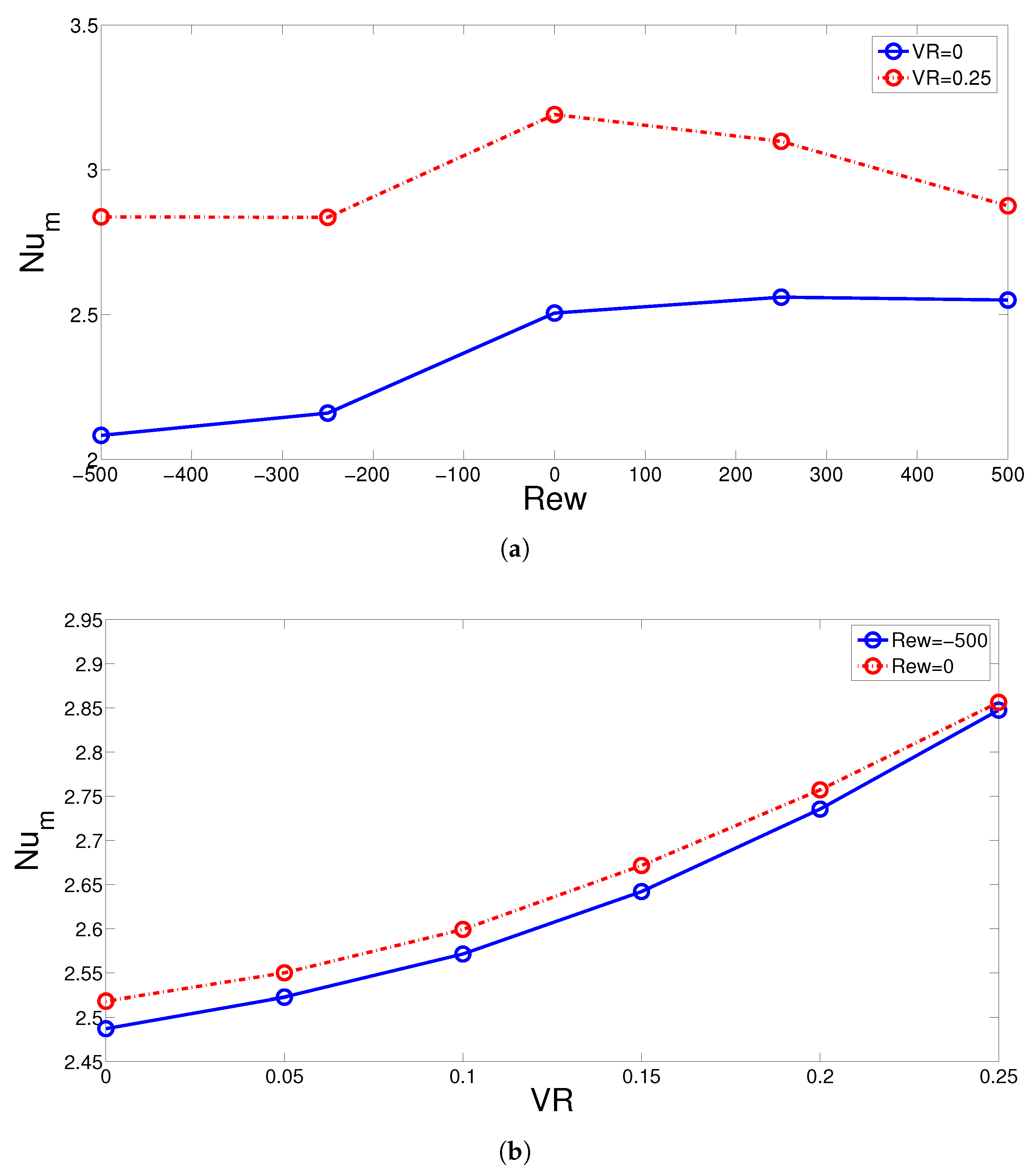
- Rotations of the CCs near the jet inlet have negative impacts of the HT enhancement for both stationary and moving hot wall cases. Reductions in the average Nu of up to 20% and 12.5% are obtained by using rotations at Rew = −500 for stationary (V = 0) and moving wall (VR = 0.25) cases.
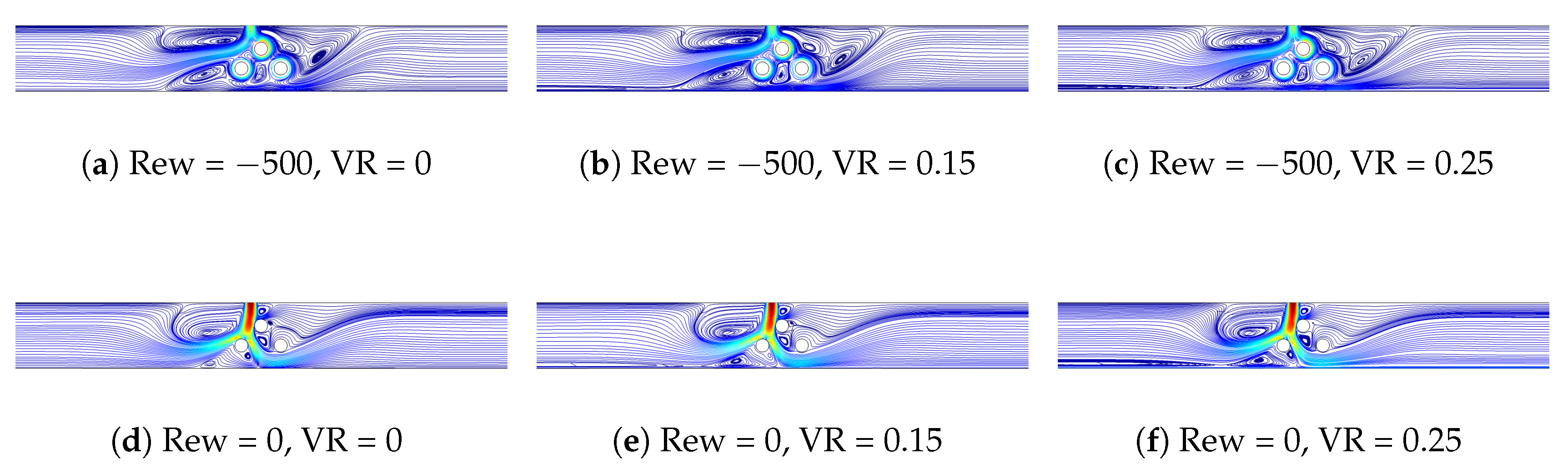
- The wall movement contributes positively to the cooling performance while HT enhancements up to 14% are achieved by wall velocity at the highest speed (VR = 0.25).
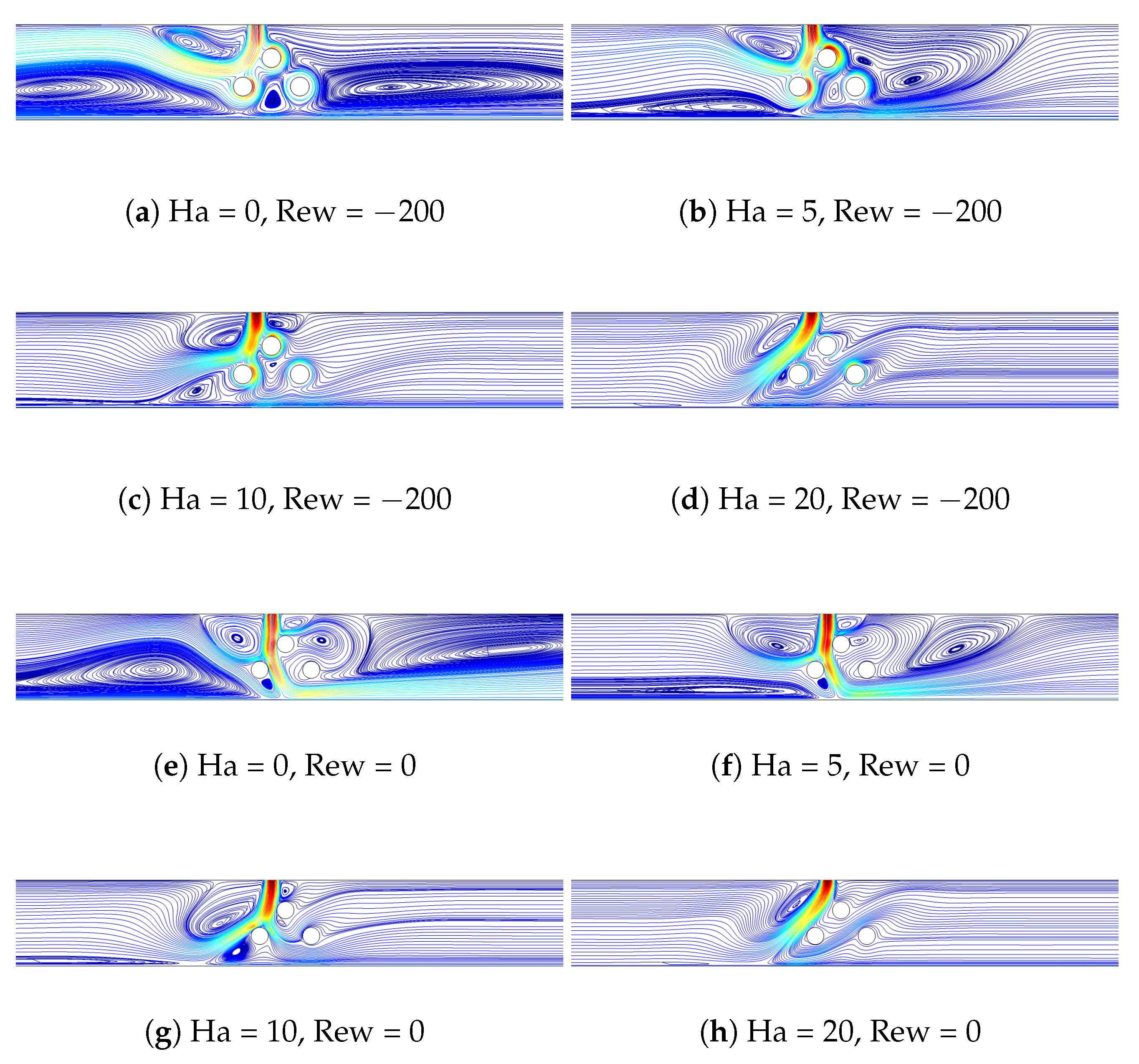
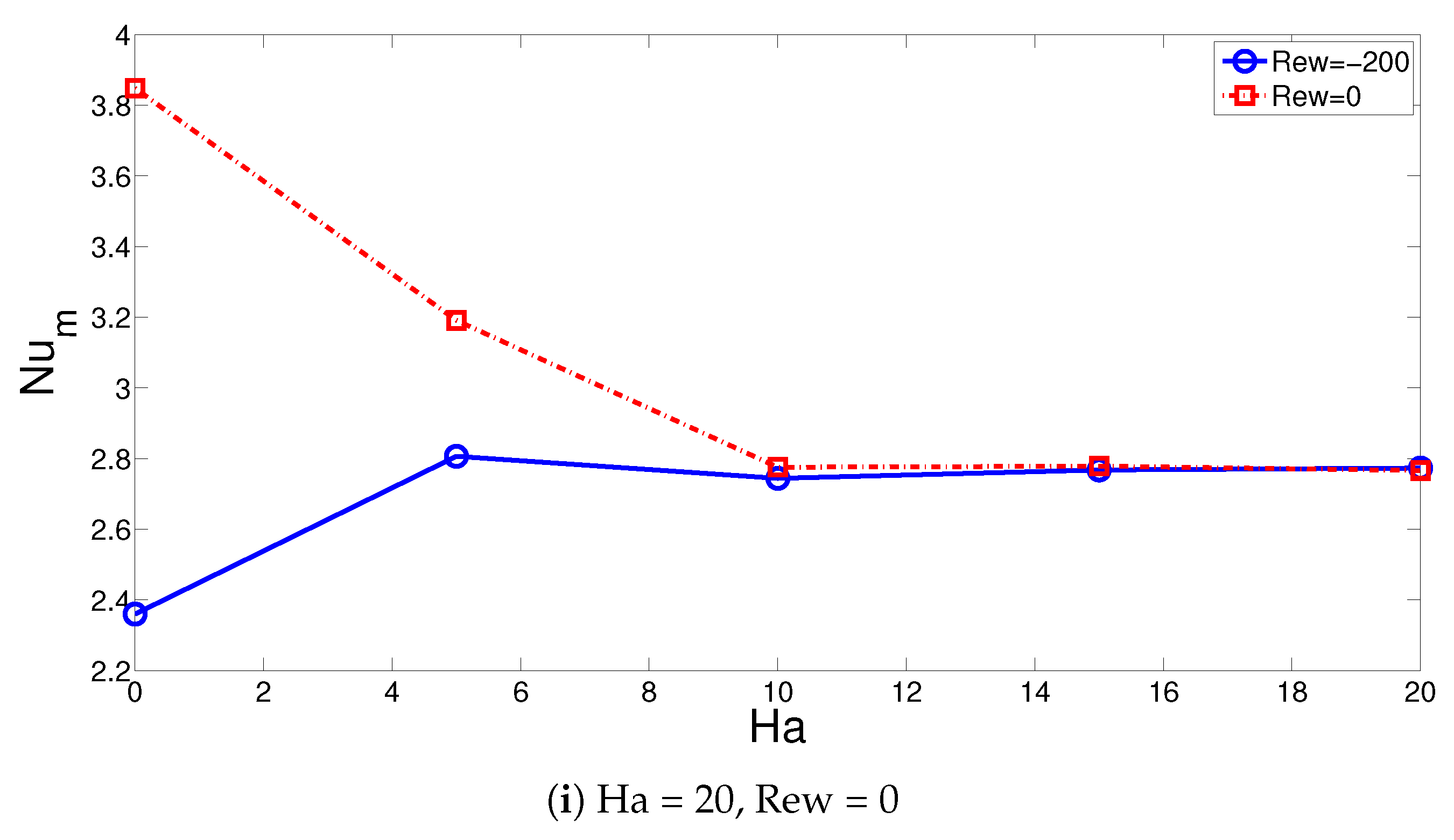
- Depending upon the activation of cylinder rotations, the impacts of MGF strength on the HT characteristics are different. For non-rotating CCs, cooling performance is reduced by about 28% until Ha = 10, while by using rotations at Rew = −200, it is increased by about 18.6%.
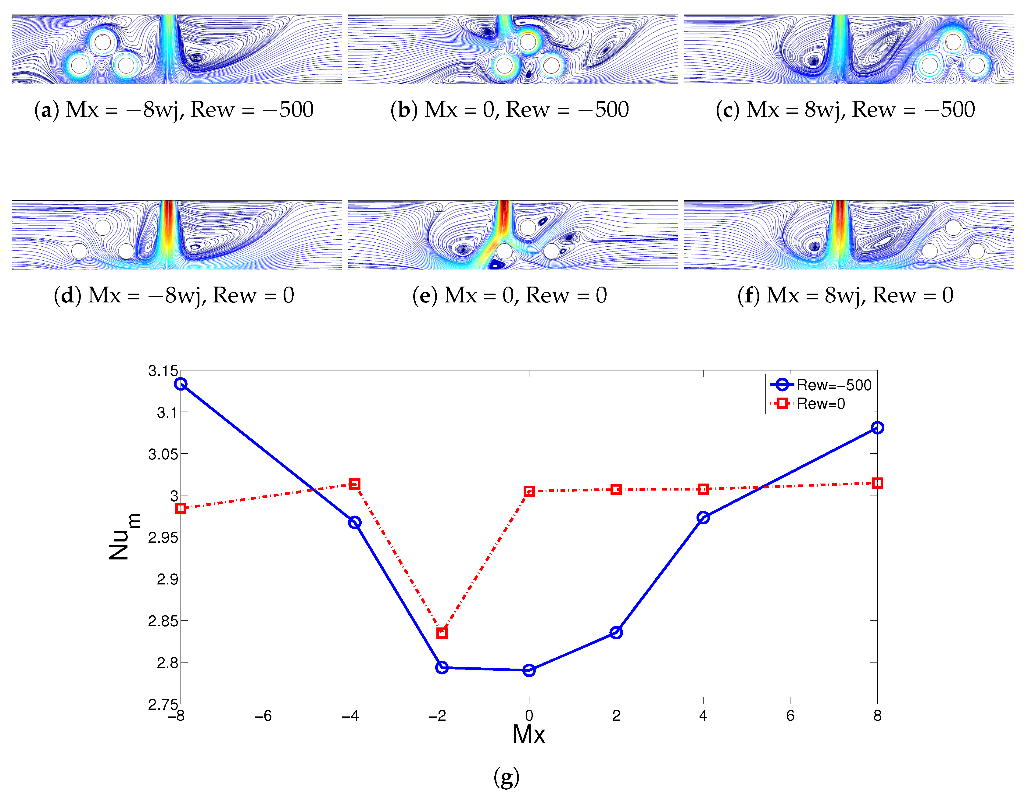
- For the rotating CC case, average Nu variations up to 12% can be achieved by varying the horizontal location of the CCs while away from the inlet, higher cooling performances are obtained.
- When the hot wall starts to move at VR = 0.25, the EG increments up to 6.25% and are obtained for non-rotating and rotating CC cases compared with the stationary wall (VR = 0) configuration.
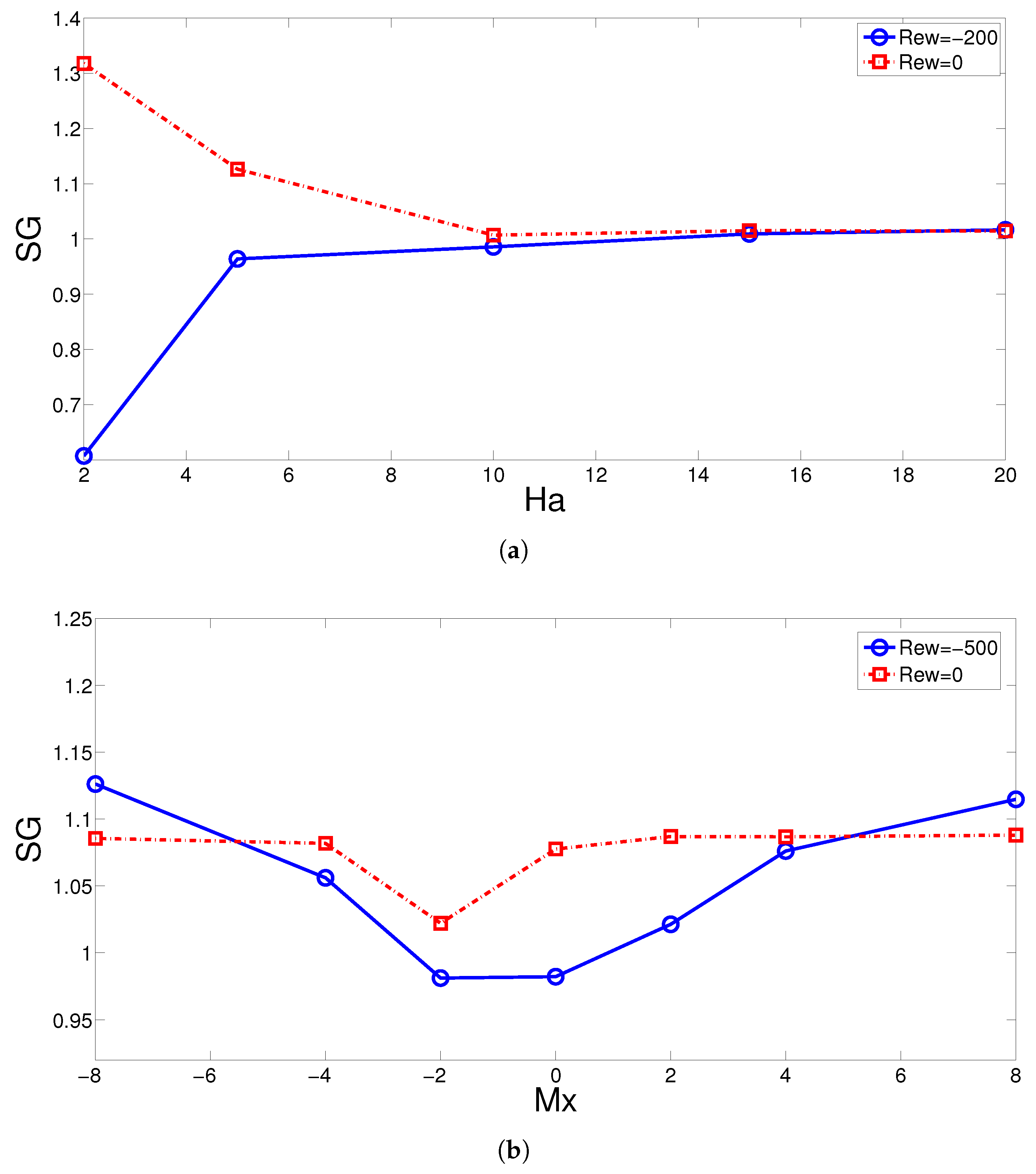
- The MGF acts to reduce the EG by about 23% for non-rotating cylinders while increment of EG by about 66% is obtained for rotating cylinders at Rew = 200. Away from the jet inlet, the EG rises.
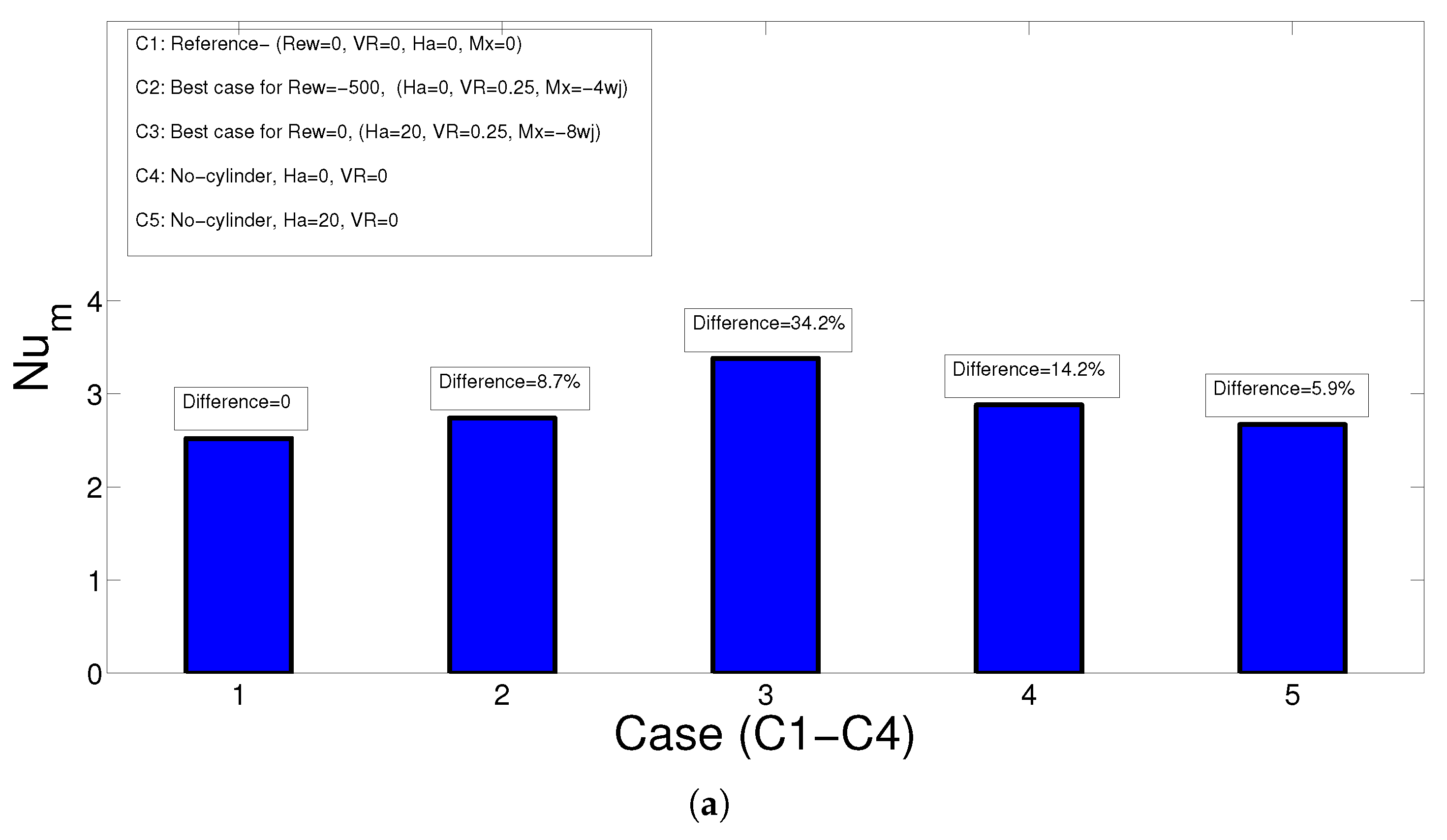
- The best configuration for the case of non-rotating CCs is achieved at (Ha, VR, Mx) = (0, 0.25, −4), and HT increment becomes 8.7% compared with the reference case of (Rew = 0, VR = 0, Ha = 0, Mx = 0). For the non-rotating CC case, the optimum set of parameters is achieved at (Ha, VR, Mx) = (20, 0.25, −8) with HT enhancement of 34.2% compared with the reference.
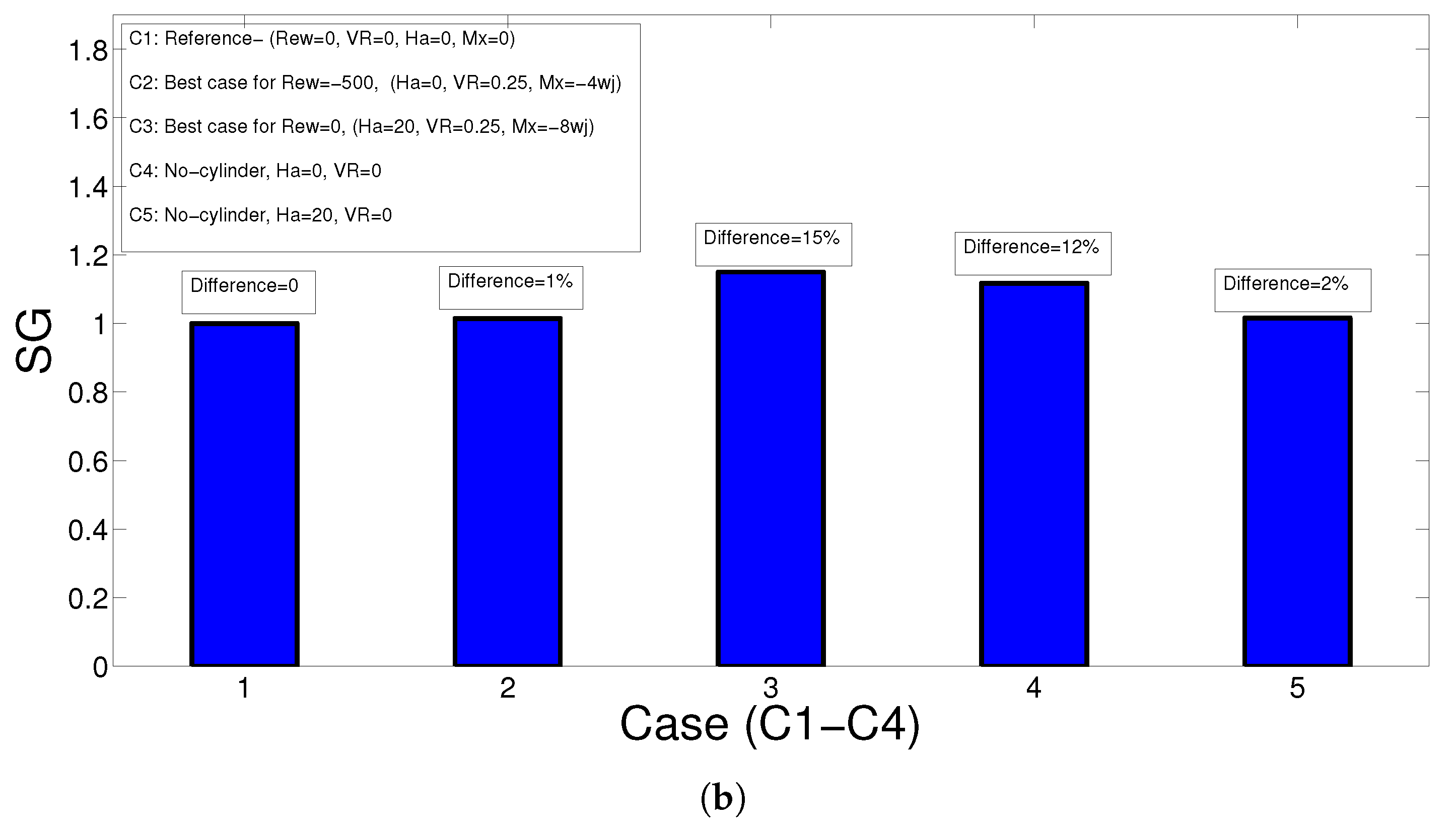
- The maximum EG is obtained for configuration with (Ha, VR, Mx) = (20, 0.25, −8) with non-rotating CCs, while the value is 15% higher than the reference case. When rotations are active at Rew = −500, the case (Ha, VR, Mx) = (0, 0.25, −4) has only 1% higher EG when compared to reference.
Author Contributions
Funding
Data Availability Statement
Conflicts of Interest
Nomenclature
| B | Magnetic field strength |
| Ha | Hartmann number |
| H | separating distance |
| h | heat transfer coefficient |
| k | thermal conductivity |
| L | plate length |
| n | unit normal vector |
| Nu | local Nusselt number |
| Nu | average Nusselt number |
| p | pressure |
| Pr | Prandtl number |
| r | cylinder radius |
| Re | Reynolds number |
| Rew | rotational Reynolds number |
| T | temperature |
| u, v | x-y velocity components |
| uc | jet velocity |
| uw | wall velocity |
| VR | velocity ratio |
| wj | slot width |
| x, y | Cartesian coordinates |
| Greek Characters | |
| thermal diffusivity | |
| magnetic field inclination | |
| non-dimensional temperature | |
| kinematic viscosity | |
| density of the fluid | |
| electrical conductivity | |
| solid volume fraction | |
| rotational speed | |
| Subscripts | |
| c | cold |
| h | hot |
| m | average |
| nf | nanofluid |
| w | wall |
References
- Javidan, M.; Moghadam, A.J. Experimental investigation on thermal management of a photovoltaic module using water-jet impingement cooling. Energy Convers. Manag. 2021, 228, 113686. [Google Scholar] [CrossRef]
- Bahaidarah, H.M. Experimental performance evaluation and modeling of jet impingement cooling for thermal management of photovoltaics. Sol. Energy 2016, 135, 605–617. [Google Scholar] [CrossRef]
- Selimefendigil, F.; Coban, S.O.; Öztop, H.F. Comparative study and hybrid modeling approach with POD for convective drying performance of porous moist object with multi-impinging jet and channel flow configurations. Int. Commun. Heat Mass Transf. 2022, 132, 105897. [Google Scholar] [CrossRef]
- Jambunathan, K.; Lai, E.; Moss, M.; Button, B. A review of heat transfer data for single circular jet impingement. Int. J. Heat Fluid Flow 1992, 13, 106–115. [Google Scholar] [CrossRef]
- Webb, B.; Ma, C. Single-Phase Liquid Jet Impingement Heat Transfer. Adv. Heat Transf. 1995, 26, 105–217. [Google Scholar]
- Tyagi, P.K.; Kumar, R.; Mondal, P.K. A review of the state-of-the-art nanofluid spray and jet impingement cooling. Phys. Fluids 2020, 32, 121301. [Google Scholar] [CrossRef]
- Kakaç, S.; Pramuanjaroenkij, A. Single-phase and two-phase treatments of convective heat transfer enhancement with nanofluids–A state-of-the-art review. Int. J. Therm. Sci. 2016, 100, 75–97. [Google Scholar] [CrossRef]
- Pordanjani, A.H.; Aghakhani, S.; Afrand, M.; Mahmoudi, B.; Mahian, O.; Wongwises, S. An updated review on application of nanofluids in heat exchangers for saving energy. Energy Convers. Manag. 2019, 198, 111886. [Google Scholar] [CrossRef]
- Chamkha, A.J.; Molana, M.; Rahnama, A.; Ghadami, F. On the nanofluids applications in microchannels: A comprehensive review. Powder Technol. 2018, 332, 287–322. [Google Scholar] [CrossRef]
- Sheikholeslami, M.; Rokni, H.B. Simulation of nanofluid heat transfer in presence of magnetic field: A review. Int. J. Heat Mass Transf. 2017, 115, 1203–1233. [Google Scholar] [CrossRef]
- M’hamed, B.; Sidik, N.A.C.; Yazid, M.N.A.W.M.; Mamat, R.; Najafi, G.; Kefayati, G. A review on why researchers apply external magnetic field on nanofluids. Int. Commun. Heat Mass Transf. 2016, 78, 60–67. [Google Scholar] [CrossRef]
- Mohammadpour, J.; Lee, A. Investigation of nanoparticle effects on jet impingement heat transfer: A review. J. Mol. Liq. 2020, 316, 113819. [Google Scholar] [CrossRef]
- Li, P.; Guo, D.; Liu, R. Mechanism analysis of heat transfer and flow structure of periodic pulsating nanofluids slot-jet impingement with different waveforms. Appl. Therm. Eng. 2019, 152, 937–945. [Google Scholar] [CrossRef]
- Manca, O.; Mesolella, P.; Nardini, S.; Ricci, D. Numerical study of a confined slot impinging jet with nanofluids. Nanoscale Res. Lett. 2011, 6, 188. [Google Scholar] [CrossRef] [PubMed]
- Yousefi-Lafouraki, B.; Ramiar, A.; Mohsenian, S. Entropy generation analysis of a confined slot impinging jet in a converging channel for a shear thinning nanofluid. Appl. Therm. Eng. 2016, 105, 675–685. [Google Scholar] [CrossRef]
- Nakharintr, L.; Naphon, P. Magnetic field effect on the enhancement of nanofluids heat transfer of a confined jet impingement in mini-channel heat sink. Int. J. Heat Mass Transf. 2017, 110, 753–759. [Google Scholar] [CrossRef]
- Selimefendigil, F.; Öztop, H.F. Hybrid nano-jet impingement cooling of a curved elastic hot surface under the combined effects of non-uniform magnetic field and upper plate inclination. J. Magn. Magn. Mater. 2022, 561, 169684. [Google Scholar] [CrossRef]
- Hashemi-Tilehnoee, M.; del Barrio, E.P. Magneto laminar mixed convection and entropy generation analyses of an impinging slot jet of Al2O3-water and Novec-649. Therm. Sci. Eng. Prog. 2022, 36, 101524. [Google Scholar] [CrossRef]
- Roslan, R.; Saleh, H.; Hashim, I. Effect of rotating cylinder on heat transfer in a square enclosure filled with nanofluids. Int. J. Heat Mass Transf. 2012, 55, 7247–7256. [Google Scholar] [CrossRef]
- Costa, V.A.F.; Raimundo, A.M. Steady mixed convection in a differentially heated square enclosure with an active rotating circular cylinder. Int. J. Heat Mass Transf. 2010, 53, 1208–1219. [Google Scholar] [CrossRef]
- Selimefendigil, F.; Öztop, H.F. Mixed convection in a PCM filled cavity under the influence of a rotating cylinder. Sol. Energy 2020, 200, 61–75. [Google Scholar] [CrossRef]
- Jiang, L.; Lyu, Y.; Zhu, P.; Gao, W.; Liu, Z. Numerical investigation of conjugate heat transfer on a rotating disk under round liquid jet impingement. Int. J. Therm. Sci. 2021, 170, 107097. [Google Scholar] [CrossRef]
- Lallave, J.C.; Rahman, M.M.; Kumar, A. Numerical analysis of heat transfer on a rotating disk surface under confined liquid jet impingement. Int. J. Heat Fluid Flow 2007, 28, 720–734. [Google Scholar] [CrossRef]
- Iacovides, H.; Kounadis, D.; Launder, B.E.; Li, J.; Xu, Z. Experimental study of the flow and thermal development of a row of cooling jets impinging on a rotating concave surface. J. Turbomach. 2005, 127, 222–229. [Google Scholar] [CrossRef]
- Selimefendigil, F.; Öztop, H.F. Analysis and predictive modeling of nanofluid-jet impingement cooling of an isothermal surface under the influence of a rotating cylinder. Int. J. Heat Mass Transf. 2018, 121, 233–245. [Google Scholar] [CrossRef]
- Bejan, A. Fundamentals of exergy analysis, entropy generation minimization, and the generation of flow architecture. Int. J. Energy Res. 2002, 26. [Google Scholar] [CrossRef]
- Bejan, A. Entropy Generation Minimization: The Method of Thermodynamic Optimization of Finite-Size Systems and Finite-Time Processes; CRC Press: Boca Raton, FL, USA, 2013. [Google Scholar]
- Narayan, G.P.; Lienhard V, J.H.; Zubair, S.M. Entropy generation minimization of combined heat and mass transfer devices. Int. J. Therm. Sci. 2010, 49, 2057–2066. [Google Scholar] [CrossRef]
- Tayebi, T.; Dogonchi, A.S.; Karimi, N.; Ge-JiLe, H.; Chamkha, A.J.; Elmasry, Y. Thermo-economic and entropy generation analyses of magnetic natural convective flow in a nanofluid-filled annular enclosure fitted with fins. Sustain. Energy Technol. Assess. 2021, 46, 101274. [Google Scholar] [CrossRef]
- Ellahi, R.; Sait, S.M.; Shehzad, N.; Ayaz, Z. A hybrid investigation on numerical and analytical solutions of electro-magnetohydrodynamics flow of nanofluid through porous media with entropy generation. Int. J. Numer. Methods Heat Fluid Flow 2020, 30, 834–854. [Google Scholar] [CrossRef]
- Li, J.; Kleinstreuer, C. Entropy generation analysis for nanofluid flow in microchannels. J. Heat Transf. 2010, 132, 122401. [Google Scholar] [CrossRef]
- Mahian, O.; Kianifar, A.; Kleinstreuer, C.; Mohd A, A.N.; Pop, I.; Sahin, A.Z.; Wongwises, S. A review of entropy generation in nanofluid flow. Int. J. Heat Mass Transf. 2013, 65, 514–532. [Google Scholar] [CrossRef]
- Huminic, G.; Huminic, A. Entropy generation of nanofluid and hybrid nanofluid flow in thermal systems: A review. J. Mol. Liq. 2020, 302, 112533. [Google Scholar] [CrossRef]
- Aghakhani, S.; Pordanjani, A.H.; Afrand, M.; Sharifpur, M.; Meyer, J.P. Natural convective heat transfer and entropy generation of alumina/water nanofluid in a tilted enclosure with an elliptic constant temperature: Applying magnetic field and radiation effects. Int. J. Mech. Sci. 2020, 174, 105470. [Google Scholar] [CrossRef]
- Barnoon, P.; Toghraie, D.; Eslami, F.; Mehmandoust, B. Entropy generation analysis of different nanofluid flows in the space between two concentric horizontal pipes in the presence of magnetic field: Single-phase and two-phase approaches. Comput. Math. Appl. 2019, 77, 662–692. [Google Scholar] [CrossRef]
- Selimefendigil, F.; Öztop, H.F.; Chamkha, A.J. MHD mixed convection and entropy generation of nanofluid filled lid driven cavity under the influence of inclined magnetic fields imposed to its upper and lower diagonal triangular domains. J. Magn. Magn. Mater. 2016, 406, 266–281. [Google Scholar] [CrossRef]
- Reddy, J.N.; Gartling, D.K. The Finite Element Method in Heat Transfer and Fluid Dynamics; CRC Press: Boca Raton, FL, USA, 2010. [Google Scholar]
- Lewis, R.W.; Nithiarasu, P.; Seetharamu, K.N. Fundamentals of the Finite Element Method for Heat and Fluid Flow; John Wiley & Sons: West Sussex, UK, 2004. [Google Scholar]
- Das, S.; Biswas, A.; Das, B. Numerical analysis of a solar air heater with jet impingement?comparison of performance between jet designs. J. Sol. Energy Eng. 2022, 144, 011001. [Google Scholar] [CrossRef]
- Froissart, M.; Ziółkowski, P.; Dudda, W.; Badur, J. Heat exchange enhancement of jet impingement cooling with the novel humped-cone heat sink. Case Stud. Therm. Eng. 2021, 28, 101445. [Google Scholar] [CrossRef]
- Selimefendigil, F.; Kolsi, L.; Ayadi, B.; Aich, W.; Alresheedi, F.; Borjini, M.N. Jet impingement cooling using shear thinning nanofluid under the combined effects of inclined separated partition at the inlet and magnetic field. Eur. Phys. J. Spec. Top. 2022, 231, 2491–2508. [Google Scholar] [CrossRef]
- Zhang, T.; Che, D. Double MRT thermal lattice Boltzmann simulation for MHD natural convection of nanofluids in an inclined cavity with four square heat sources. Int. J. Heat Mass Transf. 2016, 94, 87–100. [Google Scholar] [CrossRef]
- Manca, O.; Ricci, D.; Nardini, S.; Di Lorenzo, G. Thermal and fluid dynamic behaviors of confined laminar impinging slot jets with nanofluids. Int. Commun. Heat Mass Transf. 2016, 70, 15–26. [Google Scholar] [CrossRef]
- Chou, Y.; Hung, Y. Impingement cooling of an isothermally heated surface with a confined slot jet. ASME Trans. J. Heat Transf. 1994, 116, 479–482. [Google Scholar] [CrossRef]


Disclaimer/Publisher’s Note: The statements, opinions and data contained in all publications are solely those of the individual author(s) and contributor(s) and not of MDPI and/or the editor(s). MDPI and/or the editor(s) disclaim responsibility for any injury to people or property resulting from any ideas, methods, instructions or products referred to in the content. |
© 2023 by the authors. Licensee MDPI, Basel, Switzerland. This article is an open access article distributed under the terms and conditions of the Creative Commons Attribution (CC BY) license (https://creativecommons.org/licenses/by/4.0/).
Share and Cite
Kolsi, L.; Selimefendigil, F.; Larguech, S.; Ghachem, K.; Albalawi, H.; Alshammari, B.M.; Labidi, T. Convective Heat Transfer and Entropy Generation for Nano-Jet Impingement Cooling of a Moving Hot Surface under the Effects of Multiple Rotating Cylinders and Magnetic Field. Mathematics 2023, 11, 1891. https://doi.org/10.3390/math11081891
Kolsi L, Selimefendigil F, Larguech S, Ghachem K, Albalawi H, Alshammari BM, Labidi T. Convective Heat Transfer and Entropy Generation for Nano-Jet Impingement Cooling of a Moving Hot Surface under the Effects of Multiple Rotating Cylinders and Magnetic Field. Mathematics. 2023; 11(8):1891. https://doi.org/10.3390/math11081891
Chicago/Turabian StyleKolsi, Lioua, Fatih Selimefendigil, Samia Larguech, Kaouther Ghachem, Hind Albalawi, Badr M. Alshammari, and Taher Labidi. 2023. "Convective Heat Transfer and Entropy Generation for Nano-Jet Impingement Cooling of a Moving Hot Surface under the Effects of Multiple Rotating Cylinders and Magnetic Field" Mathematics 11, no. 8: 1891. https://doi.org/10.3390/math11081891