1. Introduction
Lord and Shulman [
1] discussed expanding Fourier’s heat transfer law by including a flux-rate term and developing a general form consisting of a hyperbolic-type heat conduction equation with a limited thermal pulse speed. This would make for a better thermoelasticity framework. Green and Lindsay [
2] used relaxation time aspects that do not go against the standard Fourier law of heat transfer to build a thermoelastic framework that predicts a heat transfer speed limit based on the temperature change rate. Further developments of thermoelasticity were made by Green and Naghdi [
3,
4,
5], who introduced the so-called first, second, and third (I, II, and III) models of extended thermoelasticity of homogeneous elastic materials. The mathematical formulation of the first model (GN-I) can be reduced to the classical Fourier concept of heat transfer. In contrast, both the second and third models (GN-II and GN-III) allow heat waves to move at restricted speeds. Tzou [
6] modified the microstructural evidence to propose a new model for extended thermoelasticity called the dual-phase-lag model (DPL). The vector of heat transfer and the temperature gradient both experienced two-stage delays as a result. Roy Choudhuri [
7] established the three-phase-lag version (TPL) of the heat transfer equation, which takes into account the phase delays in the thermal displacement gradient, the temperature gradient, and the heat flow vector. The DPL theory is not just useful for silicon microstructure research, but also for the study of other materials such as polymers. As a result, it is reasonable to assume that the wave-type heat conduction theories developed in this study may be applied to other materials, including microstretch thermoelastic media, because of the nature of the heat conduction process.
Several recent articles attest to the growing interest in the domain of electro-elasticity, also known as the linked mechanical and electric areas in piezoelectric materials. There are a variety of smart materials and systems, some of which include sensors, actuators, electrical and mechanical transducers, microgenerators, and ultrasonic biomechanical optoelectronic elements that make use of piezoelectric composite materials due to their high sensitivity and low mechanical losses. It is widely accepted that piezoelectric composites, which are created by incorporating piezoelectric ceramic fibers into a matrix, are ideally suited for ultrasonics. PZT fibers embedded in an epoxy matrix work wonderfully as active fiber composites for aerospace vehicle construction. Fibers in piezoelectric composites could benefit greatly from coating technology, enhancing their electromechanical characteristics. Because devices made of piezoelectric composite materials are often subjected to dynamic loads, it is very interesting to study how waves move through these materials and how covered fiber-reinforced composites made of different piezoelectric materials cause waves to spread out [
8]. Electro-mechanical loads, including electrical fields, strains, stresses, and thermal loads, are applied to smart materials and devices constructed with piezoelectric materials.
Piezoelectric materials find extensive use in fields as diverse as the medical field and aerospace applications, as well as in intelligent structure systems, MEMS, accelerometers, acoustic and pressure sensing, precision controller design, sensors for monitoring, ultrasonic transducers, piezoelectric composite systems, sound systems, and headphones [
9]. Since the nineteenth century, researchers have attempted to comprehend the phenomenon of coupling between a material’s thermomechanical response and its electric and magnetic responses. Piezoelectric materials were initially used in hydrophones in the middle of the twentieth century. The idea of composite materials that combine electrical and magnetic properties has emerged in the last two decades. These composites may display field coupling not seen in the individual components. The application of so-called composite and smart materials could be helpful for a wide range of developing vehicles, including optical and ultrasound sensors, gyroscopes, electric motors, and transducers, among many others. There are many uses for magneto-electro-elastic materials. These materials have found utility in cutting-edge fields such as lasers, supersonic gadgets, microwaves, and infrared purposes due to their ability to transform energy types [
10]. In addition, ferroelectric composites are inherently anisotropic and exhibit correlated behaviors between the interaction of mechanical, electrical, and electromagnetic interactions. Several researchers have taken advantage of the generalized theories of thermoelasticity to investigate some issues related to the motion of waves through magneto-thermoelastic and thermoelastic materials [
11,
12,
13,
14,
15,
16,
17,
18,
19].
Microscopically heterogeneous functionally graded materials (FGMs) are composite materials whose overall characteristics continually vary in one (or more) directions to mitigate the effects of singular stresses, reduce residual stresses, and improve bonding strength. Consequently, industries as varied as aerospace, automotive, marine, and biology use FGMs due to their valuable properties [
20]. Nonetheless, the design of FGMs is heavily dependent on the resulting effective characteristics and, more significantly, on how these qualities relate to microstructure to achieve the desired performance. Therefore, it is essential to predict the mechanical, thermal, and other properties of FGMs based on their microstructure and how they are spread out in space [
21].
The idea of FGM materials was first presented in 1984 in Japan as part of the space-plane project as a thermal barrier material. In the past few years, there has been more interest in studying solid mechanics problems where the flexible parameters are not constants but rather depend on where they are. The variation of elasticity coefficients due to inhomogeneity is a far more realistic scenario and, thus, the inspiration for this study. The surface of the Earth has its own irregularities, and this is because it is not uniform. The elasticity of the soil varies widely depending on where you are. The qualities of an FGM vary with its volume because its composition and structure change with time. Instead of using traditional homogeneous materials, FGMs often prove to be superior in a variety of settings. Components of aircraft engineering, turbines, and spacecraft are vulnerable to catastrophic failure when subjected to thermal shocks and very high temperatures, generating severe thermoelastic strains [
22].
The effectiveness of FGMs depends not only on the qualities and relative proportions of their material elements, but also on the designer’s skill in making the best possible use of those materials. One of the most critical steps in designing FG systems is to accurately simulate how they will respond to complex thermomechanical loads. The thermomechanical response to FGM material has been the focus of many analytical studies in recent years and has typically included reasonably simplified geometries, material properties, and boundary conditions. To determine the temperature of the functionally graded friction sections during single braking, Yevtushenko et al. [
23] developed a model of the frictional heat treatment process that considered the thermal responsiveness of materials. The system depends on how well the one-dimensional thermodynamic friction problem under steady slowing down is solved. The study in [
24] uses the finite element technique to investigate the nonlinear transient thermal stress in a cylinder of thick-walled FGM whose characteristics change with temperature. Using the Hermitian transfinite modeling technique, the researchers in the study in [
25] looked at the effects of temperature fluctuations on thermally induced stress and heat transmission in a cylinder with a thermosensitive functional grade. Peng et al. [
26] investigated the nonlocal extended thermal flexibility of an FGM microbial package and its thermally induced transient behavior. A ramp-style heating load heated the material at the left end of the microbeam. With the help of mathematics, Yevtushenko et al. [
27] predicted how a friction system composed of FGMs would generate heat. To account for frictional heating, the boundary-value problem of heat transfer between two semi-spaces that uniformly slide against each other was solved. Sharma et al. [
28] employed the finite element approach to illustrate the displacements, stresses, and strains for a spinning FGM disk of varying thicknesses (FEM). As one moves outward from the center of an FGM disk, the thickness and thermo-elastic material characteristics constantly change as an exponential and power law function. There is no assumed change to Poisson’s ratio. To assess thermoelastic phenomena, including temperature distribution, tension, and thermal stress, Go [
29] considered FG rotating circular disks. In order to calculate the thermoelastic properties of circular disks, a second-order differential equation was generated using the two-dimensional thermal flexible concept, and the finite element technique was employed to obtain an approximate solution. Dhakate et al. [
30] employed the ellipsoidal co-ordinates to investigate the axisymmetric thermo-elastic issue, whereby the functionally graded transversely isotropic cylindrical hole was subjected to the nonlinear thermal transfer equation, deformation functions, and stress distribution. With the help of a fractional order concept, Abouelregal and Mohamed [
31] looked into the thermo-mechanical elastic waves of functionally graded nanobeams (FGN) subjected to periodic flow rates. Because of the structural transition from ceramic at the bottom to metal at the top, FGN can be considered a non-homogenous structural system. Utilizing the more comprehensive theory of thermoelasticity, Abouelregal et al. [
32,
33] investigated the thermoelastic waves of a functionally graded thermo-piezoelectric fixed rod. The thermo-piezoelectric rod was grounded at both sides and heated by a variable axial element. Generalized thermoelastic functionals with gradations were studied by Abo-Dahab et al. [
34] using a non-Gaussian laser beam shaped like a narrow strip. Abouelregal and Dargail [
35] brought attention to the fact that a novel mathematical formulation for functionally graded thermally induced nanobeams (FGNB) with a customizable kernel function and delay period has been introduced. Hamilton’s principle, the Euler–Bernoulli hypothesis, Eringen’s concept, and three-phase-lag memory-dependent heat transfer form the basis of the governing equations for the suggested framework.
Because of their prevalence in so many engineering contexts, heat conduction (HC) sources that are in motion are of considerable significance. Procedures are as diverse as welding, metal cutting, milling, laser annealing/forming, metal plating, cannon firing, burning of some solid fuels, and dental work, all of which present unique challenges. Even though the basic idea of heat transfer for mobile heat transport problem analyses has been known for a long time, not many analytical solutions that can be solved with computers have been devised yet.
Intelligent structures are frequently exposed to both intermittent and constant heat sources during fabrication and reaction process procedures. Therefore, intelligent structural design methods must understand the effect, thermal response, and piezoelectric response of functionally scaled structures. For this reason, in this work, a new model incorporating the general equations describing the extended piezoelectric thermoelectric energy based on a double-phase delay will be presented. This presented model is an improvement over the traditional coupled thermoelasticity theory, which may fail to describe such problems physically. By adding two phase lags to the Fourier law of conduction of heat, the proposed dual phase lag (DPL) heat transfer model has been established to account for micro-structural influences that emerge in high-rate heat transmission. This model has a different advantage over other models in that it can be used to represent the ultra-fast heat transfer process on a small scale. The mathematical model was used to investigate how piezoelectric heat waves travel through a functionally graded (heterogeneous) rotating rod composed of an inner and an outer piezoelectric layer connected by linear elastic materials. Additionally, the piezoelectric rod is subjected to variable, moving, and dissipating heat sources. The results have the potential to generate a great deal of interest in the field of thermoplastics, in addition to the smart materials sector.
Using the successive separation method and the Laplace transform, the system of equations that describe the problem has been solved. The analytical formulas for the relevant physical quantities, such as deformations, thermoelectric stress, temperature change, and electric potential, have been assigned within the transduced field. Using an appropriate approximation algorithm, the numerical values of the different domains in the space-time domain were calculated. The results obtained were compared with those already published in the scientific literature. The effect of heterogeneity indices on the behavior of thermoelastic and functionally graded materials was demonstrated. By neglecting the heterogeneity parameter, the results for the homogeneity condition can be simply obtained.
After the discussion section, the remainder of the paper is organized as follows:
Section 2 presents the basic equations for piezoelectricity and thermoelasticity.
Section 3 presents a detailed description of the proposed problem for a rotating piezoelectric thermoelastic flexible rod.
Section 4 presents the method of solving using Laplace transforms, while
Section 5 presents a numerical algorithm for inverse Laplace calculations. In
Section 6, the results and discussion are presented. Finally,
Section 7 presents the most important conclusions.
List of Symbols
In the governing equations, represents the stress tensor, denotes the strain tensors, displays the displacement components, symbolizes the entropy, represents the heat flow, indicates elastic coefficients, are the piezoelectric parameters, are the thermal moduli, is the density of the material, specifies the specific heat, and represents the pyroelectric quantities. Additionally, characterizes the electric displacement, means the constant single delay time, symbolizes the thermal conductivity tensor, designates the temperature increment, is the primary temperature, denotes the electric field, and are dielectric parameters. Subscript commas indicate partial derivatives concerning the next variable, while overdots represent time derivatives.
2. Governing System of Equations
It is possible to formulate equations that govern thermopiezoelectricity theory for piezoelectric materials under a thermal field by the following system equations [
36,
37]:
The constitutive equations:
where
The electric displacement relationships are provided by:
It is assumed that the following conditions hold for the constants of matter: , , , and .
Often, we may classify the lag durations as either or , which we refer to as material qualities. To begin, is a simplified version of an energy equation that arises from processes such as phonon–electron interactions and phonon scattering. It was designed to investigate the flow of energy during rapid heating, which is significant since it is related to non-equilibrium thermodynamic conversion and microstructural changes that accelerate reaction rates. Therefore, may be seen as a mitigation time, which clarifies the rapid transitory effect of thermal inertia.
Tzou [
6,
38] described the dual-phase-lagging framework by developing Fourier’s law as follows:
where
and
are positive delay times. Additionally, the system is stable if
and unstable if
(see Ref. [
39]).
For piezo-thermoelastic solids, we can establish a generalized heat transport equation with a single-phase delay by using Equations (3)–(5) as:
The DPL thermal transport model has advantages in several contexts, including describing the effects of material defects and thermomechanical coupling due to ultrafast heating. Not only that, but it can also be used to describe how pulses move through liquid helium, study how delays vary in porous media, and figure out how sensitive thermal delays are in amorphous materials that are heated by an ultrafast pulse laser.
The thermo-piezoelectricity problem without body force and volume charges is governed by three supplementary equations given by:
The equations of motion (10) are written as follows by repeatedly substituting Equation (1) into Equation (10) [
36,
37]:
Differentiating Equation (5) with respect to position and using Equations (8) and (9), we find:
Assuming that piezoelectric influences are zero (, ), the fundamental system field equations simplify to the modified thermoelasticity with a single relaxation time. Additionally, the equations of the coupled thermo-piezoelectricity framework are obtained by ignoring both lagging times ( and ). Moreover, the Lord and Shulman model can be obtained by setting . It is also possible to obtain the conventional Fourier heat transport if the parameters of piezoelectric and relaxation time are all zero ( and ).
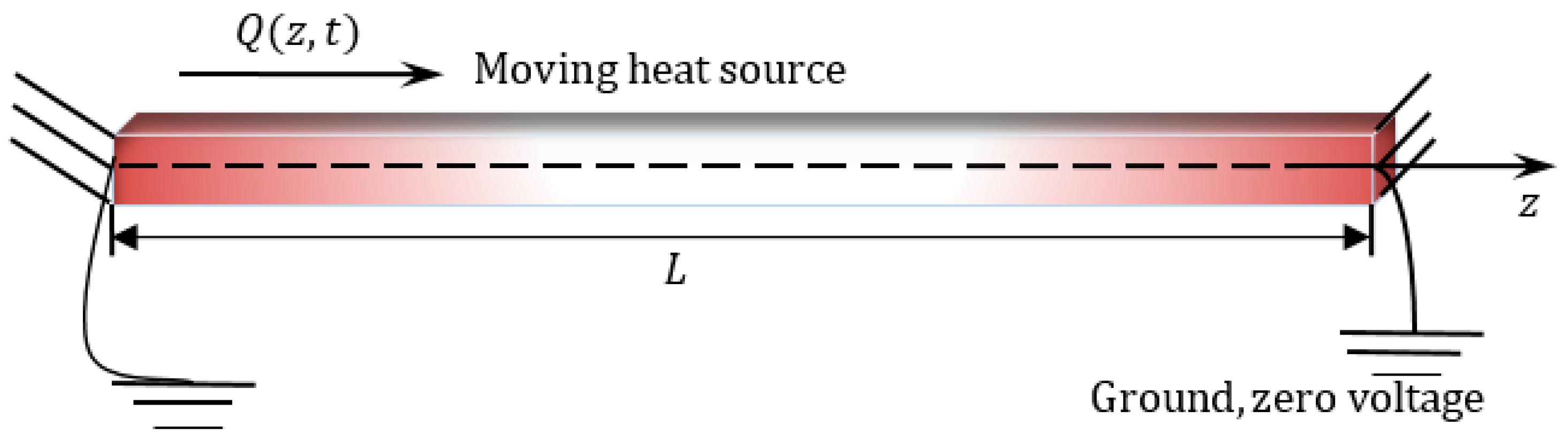
3. Problem Formulation
Here, we focus on the case of a finite rod of thermoelastic material with a functional gradation occupying the region
. We consider that the origin of the coordinates at the left edge of the piezoelectric elastic rod, as displayed in
Figure 1, was the alignment of the rod along the
-axis. In addition to being permanently attached, there is insulation on both ends to prevent heat loss. At the end,
, we assume a flat distribution of a heat source
moving at a constant velocity towards the right. We will suppose that the rod was initially motionless and at a temperature of
. It is assumed that the physical characteristics of the rod vary exponentially across its axial length.
Only due to the nature of the problem are the spatial variable and the time variable necessary to describe the state of the rod during movement and rotation. It will be taken into account that the material rotates at a constant angular velocity , where represents the unit vector along the axis of rotation. The equation of motion has been expanded to incorporate two new terms as a consequence of the rotation process. The first term accounts for the gravitational acceleration () caused by time-varying motion alone, while the second term represents the Coriolis acceleration of , where denotes the displacement vector. The distortion is also assumed to be significantly small.
In order to simplify our analysis of the one-dimensional problem, we will suppose that the electric field
, displacement
, strain
, thermal stress
, heat flow
, and electric displacement
are functions of
and
only. Because of this, we may write the governing equations as:
Equation (8) gives
, which implies that the electrical displacement is assumed to be
We will take into account that along the piezoelectric rod.
Substitution into Equation (16) results in:
As a result of plugging Equation (19) into Equations (14) and (17), we obtain:
FGMs are a type of material whose characteristics change continually with a location. Many publications discussing the mechanical properties of FGM have been published in recent years. Studies often focus on particle composites, where the dispersed phase’s volume fraction fluctuates continuously with thickness. The following formula describes how matter’s physical properties evolve exponentially in the
-axis direction [
10]:
where
represents the change of physical properties,
is assumed to be fixed, which reflects the property that a substance has when
is equal to zero (homogeneous material), and
is an indicator of heterogeneity.
When we plug the relationship (22) into the governing Equations (19)–(21), we find:
When the body is examined for the phenomenon of heat transfer, moving heat sources are those physical situations in which thermal excitation regularly changes its location and intensity. Suppose we have a stationary heat source of strength intensity
that is on at time
and moves continuously along
-axis with a constant
[
39]:
where the function
denotes the Dirac delta.
For simplicity, the following dimensionless variable quantities have been provided:
By removing the primes, we can reformulate Equations (23)–(25) as
where
When Equation (29) is substituted into Equation (15), the piezo-thermoelasticity motion equation is obtained as:
4. Solution Technique
It is assumed that the beginning conditions of FGM are given by:
If the Laplace transform defined by
is applied to any function
where
is the parameter of the Laplace transform, then the basic equations in the transformed Laplace domain under the above initial conditions (33) take the following forms:
It is possible to rewrite Equations (36) and (37) as:
where
The first- and second-order derivatives of Equation (38) are substituted into Equation (39) to produce the following displacement ODE:
where
We can write the characteristic equation of ODE Equation (40) as
where the roots
,
can be found as follows:
with
The general solution to Equation (41), describing an inhomogeneous system, can be stated as:
The parameters
,
denote the integral coefficients. In addition to that, the coefficient
takes the following form:
Similarly, removing
from Equations (38) and (39), we obtain:
where
In this case, we can express the temperature solution as:
Using Equations (46) and (50) as replacements in Equation (39), we can obtain the following:
Consequently, the final solution for
may be expressed as:
Substituting (46) and (50) into Equation (34), we then find:
where
As a result, the Laplace transform domain solution for electric potential can be found as
The solutions for electric displacement
and normalized stress
can be presented as:
We will assume that the rod is thermally insulated at the ends (
) and fixed at zero voltage at
. Therefore, the following criteria at the border will be taken into account:
After incorporating the Laplace transform into the boundary conditions (58), we obtain the system of equations in the uncertain coefficients
where
as:
By solving the above system equations, it is possible to set the values of the unknown coefficients of integration (, ).
6. Numerical Example and Results
Using the technique outlined in the earlier section, the transmission of mechanical, thermal, and electrical vibrations in an FG piezoelectric rod will be studied. To prove the aforementioned analytical approach and verify the validity of the presented theoretical research results, a numerical state of a physical substance was considered. For the numerical calculations, an FG rod with cadmium selenide on the left end was considered. In our analyses, we have taken into account the following physical characteristics of the materials we are using [
44]:
Some numerical findings are offered to analyze the theoretical outcomes achieved in the preceding sections. All of the data have been analyzed in terms of dimensionless studied field variables, and figures have been made as a function of axial distance. For various values of some parameters, such as the speed of the applied heat supply , non-homogeneous parameter , and the angular velocity of rotation , we examined the variations of the temperature change , electric potential , normal thermal stress , and displacement distribution .
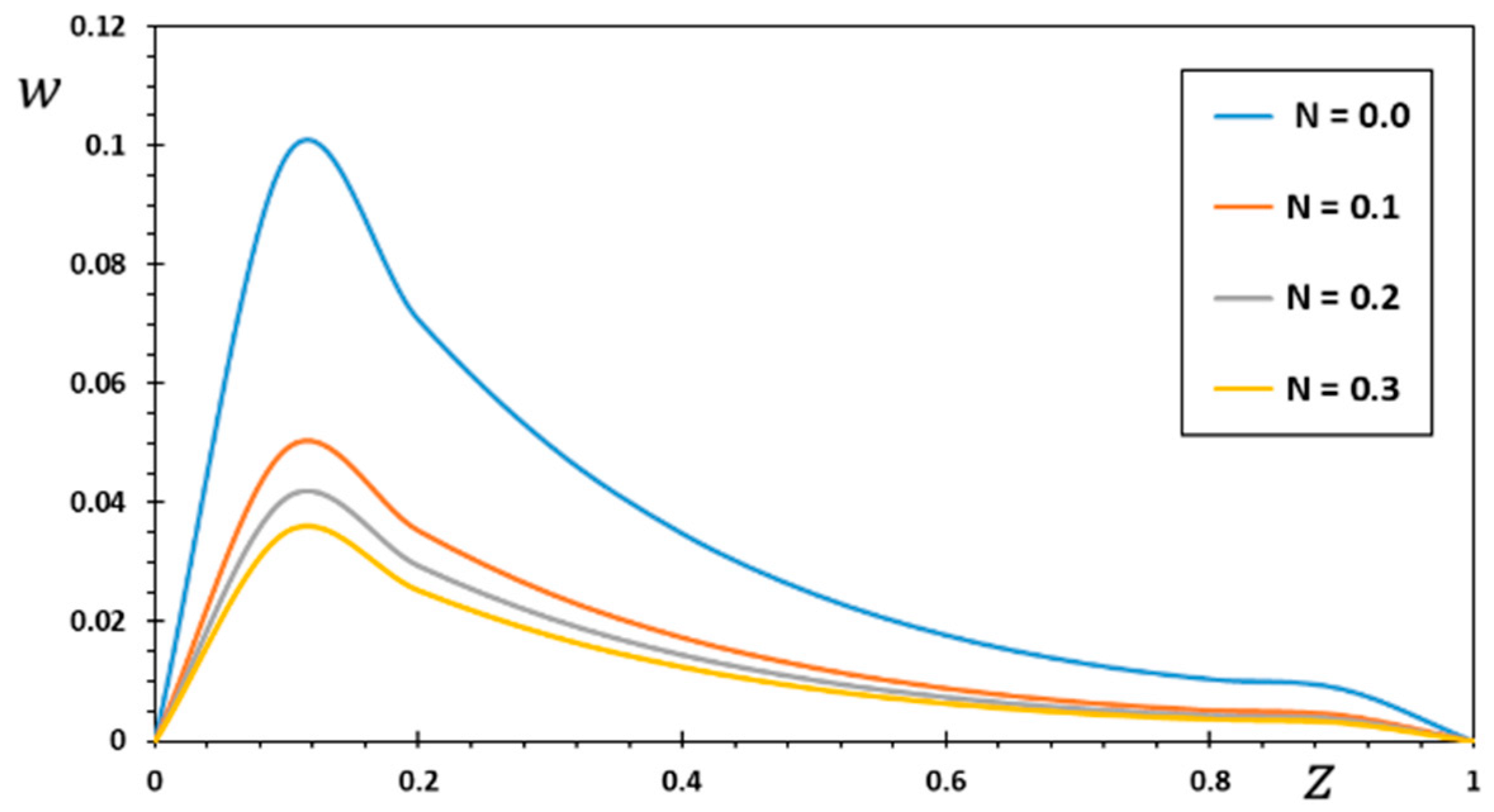
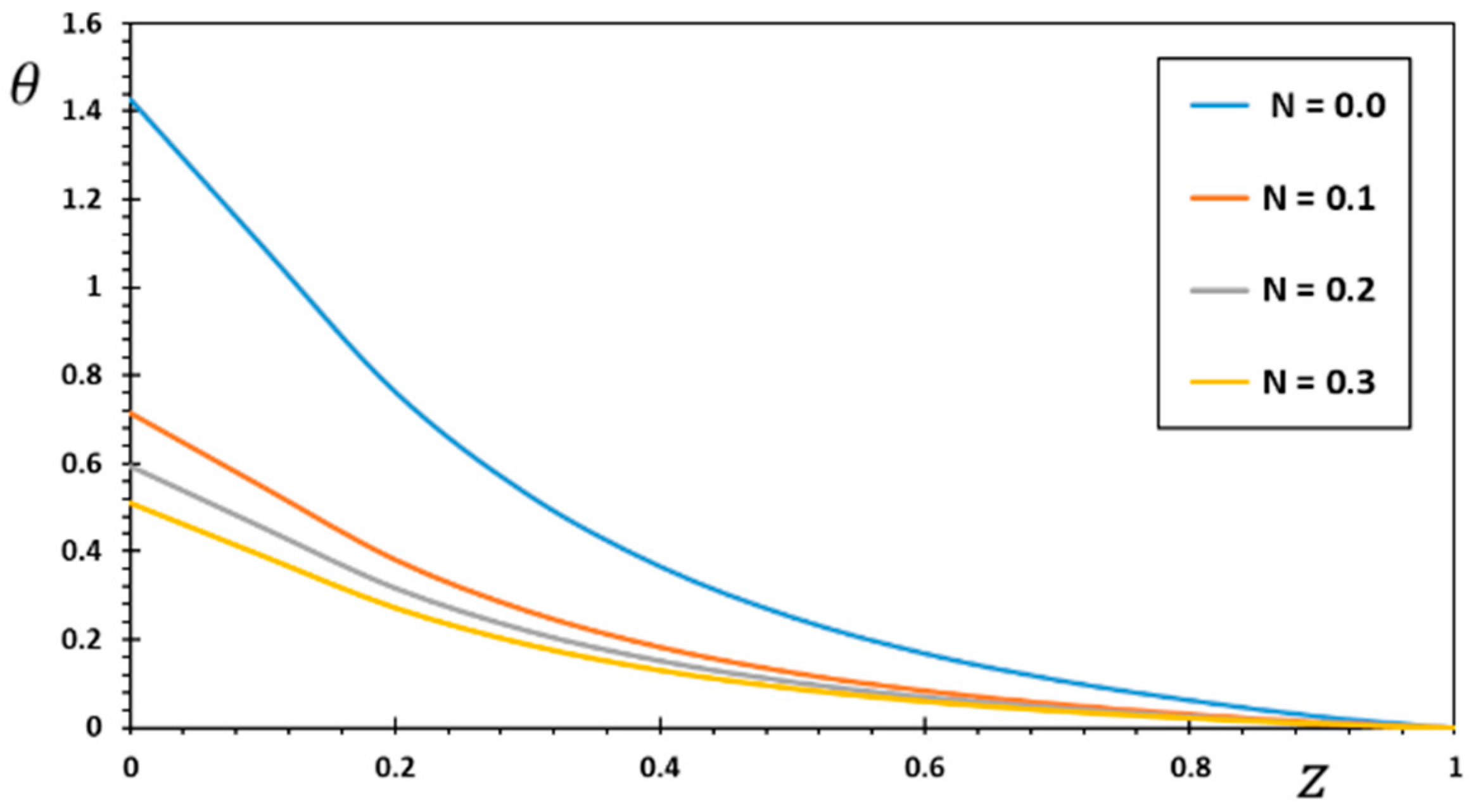
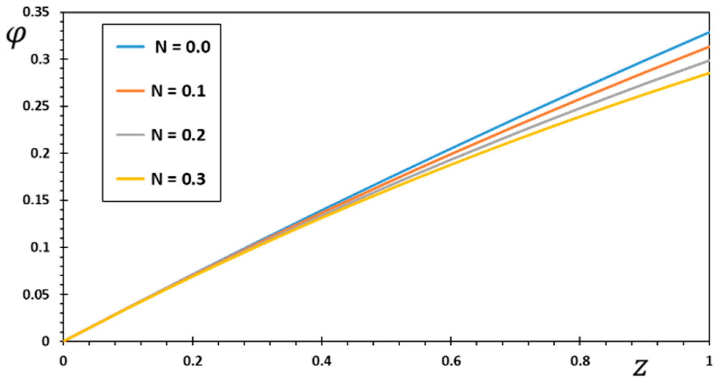
Functional Graded Materials (FGM) are one type of heterogeneous material that is specifically designed for use in high-temperature applications. This section highlights the importance of analytical studies focusing on the difficulties of transient thermoelasticity in such heterogeneous materials. In this particular instance, five distinct values of the non-homogeneous index were taken into consideration to discuss its impact on the field variables being researched. For the FG material, we used the values , , and , whereas the value represented the homogenous scenario with constant material attributes. The obtained results are displayed graphically in graphs 2–5 for the parameters , , , and , which were kept constant. These figures make it abundantly evident that the gradient indicator had a significant impact on every one of the fields that were investigated.
Figure 2 illustrates how the material inhomogeneity (
) influences the displacement
. Since the two ends of the FG rod were fixed, the expansion deformation that occurred between the two ends was confined between them. This deformation results in compressive thermal stress in the rod. It can be seen in
Figure 2 that the displacement at both ends of the FG rod satisfies the imposed boundary conditions where the displacement values are
at
and
.
Figure 2 shows that when the inhomogeneity parameter
increases, displacement decreases.
Figure 2 shows that as time passes, the temperature rises in the area of disturbance, which grows more extensively in the initial section of the piezoelectric rod. An increasing amount of displacement may be seen as time passes because the rod has been deformed by thermal expansion as a result of the external source of heat. In comparison with the results that were presented in [
45,
46], it was found that there was agreement in behavior despite the different circumstances of both problems. The effect of rod rotation was considered in this problem, but was not considered in similar cases. These results are helpful in guiding the engineering design and optimization of electro-elastic graded materials in MEMS and NEMS devices because the change in the graded factor affects the deformation of the FG rod.
Figure 3 shows the non-dimensional changes in temperature
that occur in a piezoelectric rod for various options for the inhomogeneity coefficient
. We can see from
Figure 3 that the temperature
decreases as both the amount of time elapsed and the distance traveled increase. It is also noted that the temperature
takes its maximum values at the first end, where the heat source is located, before it moves towards the other end of the rod. We also see that the amplitude of temperature
is most significant in the homogeneous area, where
equals zero, and decreases when the parameter
is increased. In addition, piezoelectric materials exhibit mechanical, electrical, and thermal coupling properties. No matter how long you are exposed to the heat source, it will always produce the same amount of heat. As the source velocity increases, the intensity of energy released per unit rod length diminishes. As a result, the amount of energy reaching any given spot in the thermally turbulent region decreases proportionally as the source velocity increases. As a result, the temperature gradient inside the rod decreases locally. In comparison to what Pal et al. found in their study [
47], the behavior was found to be similar, although the rotation effect was not present in their case. There are many uses for elastic piezoelectric materials. These materials are used in high-tech fields, including lasers, supersonic devices, infrared applications, and microwave ovens, due to their ability to transfer energy from one type to another (between mechanical, piezoelectric, and thermal energies).
With varied values of the inhomogeneity coefficient
, the electric potential
vs. the distance
can take on a wide range of shapes, as seen in
Figure 4. One can see that the electric potential quantities rise with increasing
from the graph in
Figure 4. The highest value of the electric displacement is shown when the grading indicator declines. In the illustration, each curve starts with a value of zero, and they all satisfy the limit condition that
φ must be zero for
z to be zero. The differences in electrical potentials increase as the gradient index of the rod increases. It is clear that the inhomogeneity factors do not have much of an effect on the axial component of the electric field. This means that the axial component of the electric field is mostly independent of the inhomogeneity factor. By comparing our results to those published in [
48,
49], we were able to confirm that they are in line with what other research in this field has found. Based on the value of the gradient index, it was shown that the external voltage (electric potential
) may be able to improve the device’s resistance to bending and performance.
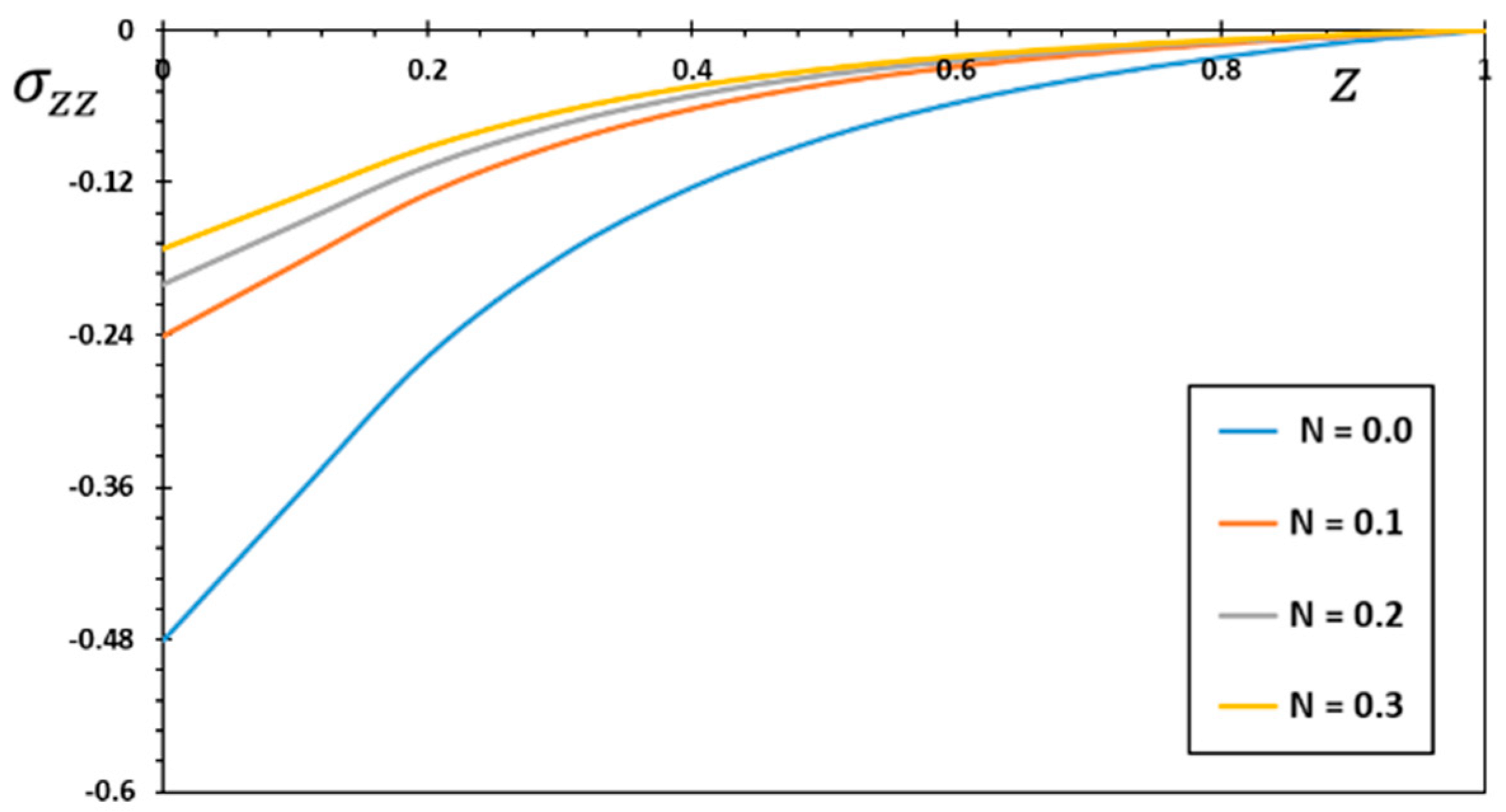
In
Figure 5, the change in thermal stress,
, was plotted against the distance
to see how the non-homogeneous parameter affects thermal stress
. Undoubtedly, compressive stress is the nature of normal stress
. When the space variable
increases, the amplitude of the pressure
in each case is seen to increase near the limit before decreasing. It is essential to take into account that these stresses express themselves as a result of a temperature change as well as the constraint posed by both ends of the
-axis extension. The highest points on the thermal stress distribution curve moved away from the tip where the heat source was applied. Because the rod is clamped at both ends, thermal expansion displacement is prevented from developing along the length of the rod. As a result, piezoelectric stress develops in the piezoelectric FG rod. As seen in this figure, when the non-homogeneous indicator
is modified, we can also detect a significant variation in the levels of thermal stress
. Such behaviors, which are discussed in the sources [
50,
51], are similar to the results and responses obtained in this article. Not only this, but different aspects of thermal stress behavior can be found in micromedia, as indicated in [
52,
53,
54,
55,
56], due to the presence of the scale effect.
Figure 2.
Variation of displacement for various values of the gradient coefficient .
Figure 2.
Variation of displacement for various values of the gradient coefficient .
Figure 3.
Variation of temperature for various values of the gradient coefficient .
Figure 3.
Variation of temperature for various values of the gradient coefficient .
Figure 4.
Variation of electric potential for various values of the gradient coefficient .
Figure 4.
Variation of electric potential for various values of the gradient coefficient .
Figure 5.
Variation of thermal stress for various values of the gradient coefficient .
Figure 5.
Variation of thermal stress for various values of the gradient coefficient .


