Article

An In-Phase Unit Slot-Opening Shift Method for Cogging Torque Reduction in Interior Permanent Magnet Machine

School of Electrical Engineering, Chongqing University, Chongqing 400044, China
*
Author to whom correspondence should be addressed.
Mathematics 2023, 11(7), 1735; https://doi.org/10.3390/math11071735
Submission received: 12 March 2023 / Revised: 26 March 2023 / Accepted: 31 March 2023 / Published: 5 April 2023

Abstract

:
The cogging torque reduction methods in permanent magnet (PM) machines are more or less FEA trial and error-based and cause undesirable side effects, such as distorted back EMF, new harmonic components, and structure asymmetry. A slot-opening grouping method can address these issues. However, it needs to model all slots in FEA design validation during practical cogging torque optimization iterations, and also leads to back-EMF reduction. In this paper, a new grouping strategy, termed in-phase unit (IPU), is introduced, together with the slot-opening angle-shift method. The slot openings with the same cogging torque distribution pattern are grouped into an IPU, and the cogging torque peaks of the slot openings within an IPU can now be interleaved. Thereby, the major harmonic components of the cogging torque are cancelled out, instead of being summed up. The IPU grouping principle, the slot-opening shift angle computation, and the selection of the harmonic order to cancel are analyzed in detail. By comparison, the proposed method not only simplifies cogging torque optimization iterations by only modeling the slots in one IPU in FEA, but also compensates for the back-EMF constant reduction. The effectiveness of the proposed methods is validated by two typical interior PM machine design cases.

1. Introduction

As permanent magnet (PM) machines exhibit high torque density and high efficiency [1,2], they have been widely employed in various electric drive systems [3,4,5]. Among many challenges in PM machine design, the reduction of motor torque ripple [6] is of high popularity. A major contributor to PM torque ripples is the cogging torque, which results in undesired vibration and acoustic noise, and affects control accuracy [7].
Compared with a surface-mounted PM (SPM) machine, the interior PM (IPM) machine has higher cogging torque due to the salient rotor structures [8]. Additionally, magnetic saturation has a great influence on torque ripple and machine drive performance [9]. Both finite-element analysis (FEA) and analytical technique [3,4,6,8,9,10,11,12] are used for the cogging torque prediction and optimization design processes. In each iteration of the optimization, the cogging torque is first predicted by the analytical method, and then the reduction schemes are applied under the analytical model, and finally the time-consuming FEA is performed for further validation.
Recently, numerous cogging torque reduction methods have been proposed. These methods can be mostly classified into two categories. The first category is rotor-side optimization. Caruso et al. [13,14] proposed a simple cogging torque minimization procedure for IPM machines by changing the rotor lamination geometry. The proposed method was essentially similar to the PM-chamfering method in SPM machines, and the main idea of both was to reduce cogging torque by changing the air gap permeance. However, the mechanism of cogging torque reduction was not explained and the optimal angle between the lamination openings and the neutral axis could not be computed quickly. Ren et al. [15] adopted an asymmetrical V-type rotor structure for IPM machines, based on the Taguchi method. However, the proposed structure led to a lower back-EMF amplitude and a significant phase shift of flux density. Wan et al. [16] and Kang et al. [17] proposed auxiliary slots on the rotor to reduce IPM cogging torque. Nevertheless, the optimized values of auxiliary slot parameters were entirely dependent on the time-consuming FEA iterations. Breton et al. [3] introduced the PM asymmetric distribution on cogging torque reduction. However, this method introduced new harmonic components. Gao et al. [18] proposed a method of shifting the magnets. However, the back-EMF amplitude and average torque were reduced, and the back-EMF waveforms also possessed a phase shift. Dosiek et al. [19] proposed a combined method of magnet shift and pole-arc optimization, in which each magnet was to be shifted relative to the adjacent magnets. Despite the effectiveness of this method, it returned the machine asymmetrical rotor structure, which led to mechanical vibration and back-EMF reduction.
The second category of cogging torque reduction methods is stator-side optimization. Zhao et al. [20] introduced a stepped slot-opening shift method with the aim to eliminate the IPM cogging torque. The method is similar to slot skewing, which maintains back-EMF symmetry while reducing its amplitude. Furthermore, the method has practical limitations when the stack length is relatively short. Hwang et al. [21,22] proposed a tooth-pairing method based on the energy perspective. However, only the fundamental frequency component of cogging torque was eliminated and the higher harmonics remained. In addition, the cogging torque would even increase for specific tooth widths. Abbaszadeh et al. [23] obtained the optimal slot-opening shift angle for cogging torque reduction based on the response surface method. However, the method can only be applied to PM machines with an integral number of slots per pole. It is also not straightforward to compute the optimum shift angle. Wang et al. [7] investigated the uneven tooth distribution option to reduce SPM cogging torque. However, the three-phase back EMF became slightly distorted.
The cogging torque reduction methods in permanent magnet machine design are more or less FEA trial and error-based and cause undesirable side effects, such as distorted back EMF, new harmonic components, and structure asymmetry. A slot-opening grouping method [24] by Liu et al. addresses these issues. A few adjacent slot openings are divided into a group. All of the slot openings in one group are shifted relative to the other groups in order to eliminate specific cogging torque harmonics. However, it needs to model all slots in FEA validation during the practical cogging torque optimization iterations. In addition, the fundamental frequency amplitude of back EMF and average electromagnetic torque were reduced based on the method.
In this paper, a new grouping strategy, termed in-phase unit (IPU), is introduced, together with the slot-opening angle-shift method. By comparison, the proposed method not only solves the stator asymmetry issue, as with the existing slot-opening grouping method, but also simplifies the cogging torque optimization iterations, since it only needs to model the slots in one IPU in FEA design validation. In addition, the proposed method is applicable for both PM machines (IPM or SPM machines) with fractional and integral numbers of slots per pole.
In Section 2.1, the IPU concept is proposed, and the slot openings with the same pattern of cogging torque distribution around the circumference are grouped into an IPU. Subsequently, in Section 2.2, the slot openings within an IPU are shifted with the proposed shift angle derivation method, so that the major cogging torque harmonics of each IPU are cancelled out, instead of being summed up. In Section 2.3, it is derived that some orders of cogging torque harmonics of all the IPUs are inherently cancelled out, while the other orders of harmonics are added up when all IPUs’ cogging torques are summed up. Therefore, these harmonic orders are screened as the ones to cancel by the proposed slot-opening angles shifting in each IPU. In Section 2.4, the complete process of cogging torque reduction is introduced, where the pole-arc coefficient optimization-based pre-process and post-process steps are introduced before and after the IPU slot-opening shift. Therefore, back-EMF reduction caused by IPU slot-opening shift is well compensated. In Section 3, the effectiveness of the proposed method is validated numerically using two interior PM machine design cases. Notably, only slot openings of one IPU are needed in FEA to validate the cogging torque reduction in design iterations. Section 4 concludes the paper.

2. The Proposed IPU-Based Slot-Opening Shift Method

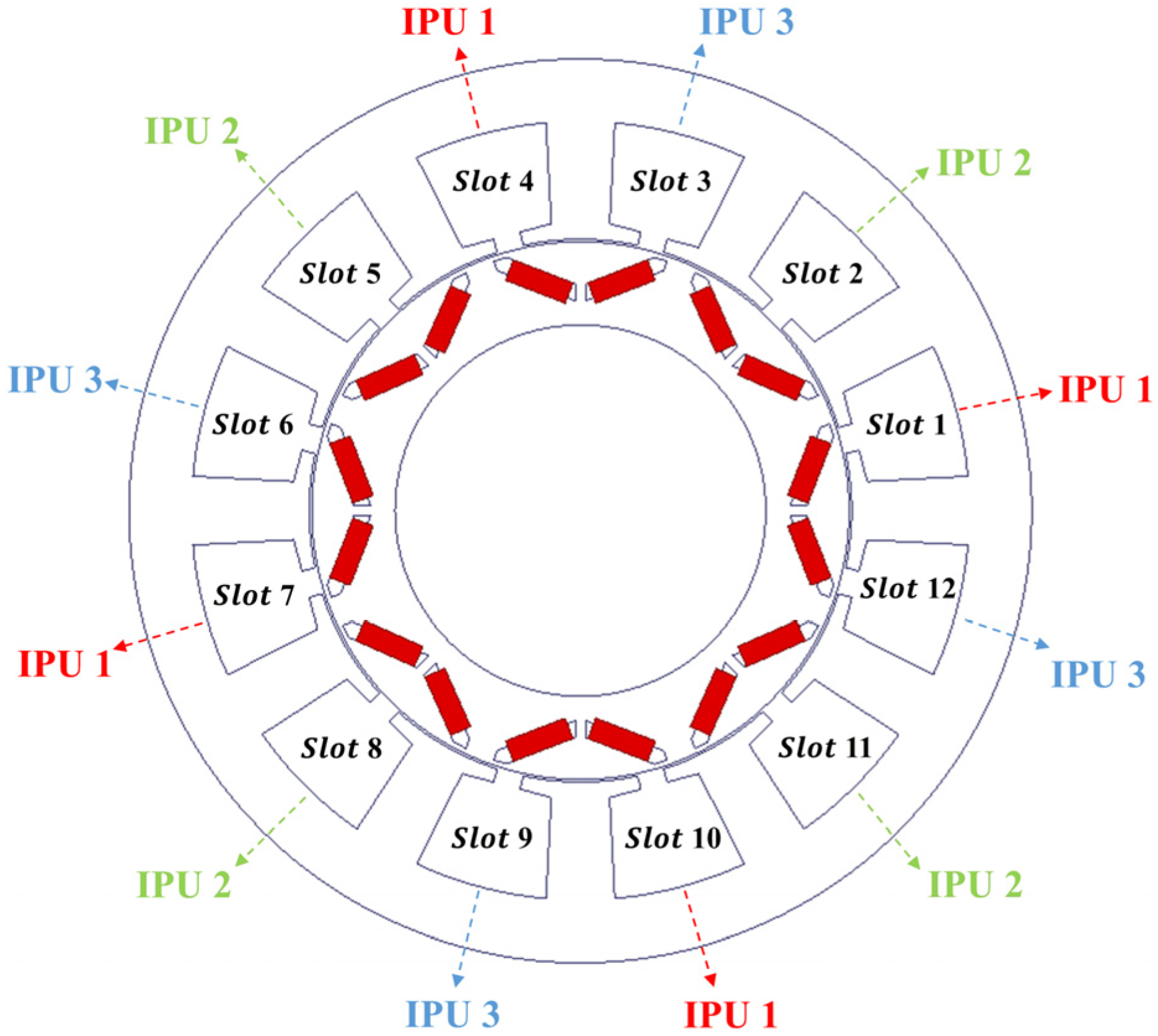
2.1. The Introduction of IPU

In PM machines, the cogging torque generated from a single-stator slot opening could be expressed as
T s s ( α ) = n = 1 T s s _ n   sin ( 2 p n α )
where n is the harmonic order, T s s ( α ) is the cogging torque generated by a single slot opening, T s s _ n is the Fourier expansion coefficient of T s s ( α ) , p is the pole-pair number, and α is the relative angle between the stator slot opening and the rotor.
As for the cogging torque distribution of the adjacent slot opening, there is a phase angle offset from (1), so that the cogging torque for any slot opening indexed by i     ( 1 i N s ) can be expressed by
T s s _ i ( α , i ) = n = 1 T s s _ n   sin { 2 p n [ α + 2 π ( i 1 ) / N s ] }
where T s s _ i ( α , i ) is the cogging torque generated by the ith slot opening, and N s is the slot number.
By defining N c as the least common multiple among 2 p and N s , κ = N c / N s and λ = N c / 2 p , where both κ and λ are prime numbers for each other. Equation (2) could be rewritten as
T s s _ i ( α , i ) = n = 1 T s s _ n   sin { n [ 2 p α + 2 π ( i 1 ) κ / λ ] }
From (3), the phase angle Δ φ between the ith and (i + j)th slot openings can be expressed as
Δ φ ( j ) = 2 π j κ λ
Observed from (4), Δ φ ( j ) is an integral multiple of 2 π only when j is an integral multiple of λ . It indicates that the stator slot openings with λ slot pitches apart have the same cogging torque distribution pattern, i.e., the harmonic components of the patterns are all in phase. As discussed in the Introduction, the first category of cogging torque reduction methods is on the rotor side, where magnets can be shifted [18], or magnet spans (pole-arc) can be changed [19]. Since our proposed shift method is of the first category, only the stator slot openings are to be shifted here.
The prior discussion can be illustrated with an 8-pole, 12-slot machine, as in Figure 1, where the cogging torque of each stator slot opening is shown in Figure 2. It is determined that the cogging torque distribution of the slots 1, 4, 7, and 10 are in phase. It is hence proposed that these stator slots are defined as an in-phase unit (IPU). Two more IPUs exist for this machine, i.e., IPU2 with the slots 2, 5, 8, and 11, and IPU3 with the slots 3, 6, 9, and 12.
As shown in Figure 1 and Figure 2, the cogging torque spatial distribution of the slot openings in different IPUs only differs by angle offset.

2.2. The Proposed IPU Slot-Opening Shift

As discussed above, all the slot openings within an IPU have the same overlapped pattern of cogging torque spatial distribution around the circumference. It is proposed here that the cogging torque peaks of the slot openings within an IPU are to be interleaved. More specifically, the harmonics of the cogging torque can be cancelled out, instead of being summed up. Basically, the slot openings within an IPU are to be grouped up in some way that would shift their angles to cancel out a specific order of harmonic. Multiple orders of harmonics are to be cancelled out, with multiple iterations of grouping and shifting.
First, as illustrated in Figure 3, the number of slot openings in an IPU ( η ) is to be factored out as
η = υ = 1 x f υ
where each factor must be a prime number. The factor x indicates the number of iterations of the slot-opening shift. In each iteration, the slot openings of an IPU are to be grouped up and shifted in order to cancel out one harmonic in the cogging torque.
Additionally, as illustrated in Figure 3, each factor indicates the number of basic units in each group for one iteration. In the first iteration, the basic units are the slot openings in an IPU, these units are grouped up with the adjacent ones along the sequence, and the number of units in a group is the factor f1. Each unit within a group is to be shifted by a certain angle to cancel out one order of harmonic in the total IPU cogging torque. In the second iteration, each group in the preceding iteration becomes a basic unit for the second round of grouping. Again, the adjacent units are grouped up, and the number of units in each group in the second iteration is factor f2. Each unit (with corresponding slot openings) within a group is to be shifted by a certain angle to cancel out the next order of harmonic in the total IPU cogging torque. The iterations are performed x times.
Taking a 6P48S motor as an example, each IPU has six slot openings, so it will be factored out as two and three. The first iteration uses the groups of two units (slot openings), and the second iteration uses the groups of three units. As for the example of a 12P36S motor, each IPU has 12 slot openings, so it will be factored out as 2, 2 and 3. There will be three iterations.
In the first iteration, one specific order of harmonic is eliminated by incrementally shifting the slot openings in a group. Additionally, note that these slot openings should all have the same initial angle. Therefore, the nth harmonic expression of the cogging torque of the group is established in (6) with the unknown shift angle, which is then solved by setting (6) as zero.
T IPU _ group cog _ n ( α , n ) = T ss _ n i = 1 f 1 sin [ 2 p n ( α + i θ shift _ n ) ]
where the cogging torque harmonic expression of a few single slot openings within a group of the IPU are summed up.
Equation (6) can be transformed into
T IPU _ group cog _ n ( α , n ) = T ss _ n   i = 1 f 1 sin ( 2 p n θ shift _ n i + 2 p n α ) = T ss _ n   i = 1 f 1 [ sin ( 2 p n θ shift _ n i ) cos ( 2 p n α ) + cos ( 2 p n θ shift _ n i ) sin ( 2 p n α ) ] = T ss _ n   [ cos ( 2 p n α ) i = 1 f 1 sin ( 2 p n θ shift _ n i ) + sin ( 2 p n α ) i = 1 f 1 cos ( 2 p n θ shift _ n i ) ]
To simplify the summing up expression, the following mathematical relations are needed.
{ i = 1 B sin ( A i ) = sin ( B A / 2 ) sin [ ( B + 1 ) A / 2 ] sin ( A / 2 ) i = 1 B cos ( A i ) = sin ( B A / 2 ) cos [ ( B + 1 ) A / 2 ] sin ( A / 2 )
When A and B in (8) are substituted with 2 p n θ shift _ n and f 1 terms in (7), Equation (7) can be rewritten as
T IPU _ group cog _ n ( α , n ) = T ss _ n { cos ( 2 p n α ) sin ( p n θ shift _ n f 1 ) sin [ p n θ shift _ n ( f 1 + 1 ) ] sin ( p n θ shift _ n ) + sin ( 2 p n α ) sin ( p n θ shift _ n f 1 ) cos [ p n θ shift _ n ( f 1 + 1 ) ] sin ( p n θ shift _ n ) } = T ss _ n sin ( p n θ shift _ n f 1 ) sin ( p n θ shift _ n ) sin [ 2 p n ( α + f 1 + 1 2 θ shift _ n ) ]
Therefore, by setting (9) as zero, i.e., the specific order of harmonics of the cogging torque of a group of slot openings in an IPU is cancelled out, the shift angle can be solved as
θ shift _ n = π p n f 1
In the second iteration, a new order of harmonic is to be cancelled out. Even though the slot openings of each unit in the second-round group have f1 different angles (increment step of θshift_n), the other units also have slot openings with the same set of different angles. Therefore, in the second iteration, a group has f2 units, each unit has one slot opening with the same angle as one slot opening in the other units, so that there will be f2 slot openings with the same angle. Thereafter, if the units are shifted to cancel out a new order of harmonic, the shift angle (incremental step) can be similarly obtained with the derivation in (6)–(9), and the same Equation (10) applies for subsequent iterations.
The sequence of the units within a group should be assigned with a shift angle with an increment step of θshift_n, starting from the first one in the sequence. However, in each iteration, the number of units in each group (f1, f2…or fx) can be either two, or another prime number. Therefore, there are two different ways of shifting angle assignments along the unit sequence within a group.
In the case of a group of two, two adjacent units are paired up and the slot-opening shift angle is set as ±θshift_n/2.
In the case of the other prime numbers k (such as three, five, seven, etc.), the shift angle assignment is different. Taking three units per group, for example, the shift angles of the three adjacent units are −θshift_n, 0, and θshift_n, respectively. As for the case with k units per group, the shift angles of the k units are −(k − 1) θshift_n/2…, −θshift_n, 0, θshift_n,…(k−1) θshift_n/2, respectively. Note that the shift angle of the unit in the middle of the sequence is zero, in order to keep symmetry.
Note that the same set of shift angles for each slot opening of an IPU obtained in one iteration is also applied to other IPUs. Obviously, all of the slot openings in the motor are shifted in each iteration, so that the final shift angle of each slot opening is the sum of x shift angles obtained in x iterations.

2.3. Screening for the Right Harmonic Orders to Cancel

As discussed above, the number of harmonic orders to cancel is limited, since it is the number of factors from the number of IPU slot-opening. Therefore, it is important to screen for the harmonic orders to cancel. The cogging torque spatial distribution of different IPUs differs by angle offsets. It is derived here that some orders of harmonics are inherently cancelled out, while the other orders of harmonics are added up, when all IPUs’ cogging torques are summed up. Therefore, these harmonic orders are the ones to cancel, by shifting slot-opening angles in each IPU, as discussed in Section 2.2.
Based on the expression of the single-slot-opening cogging torque (3), any specific order of harmonic in the cogging torque of an IPU is expressed as
T IPU _ i cog _ n ( α , n , i ) = η T ss _ n   sin [ 2 p n α + 2 π n ( i 1 ) κ / λ ]
Thereafter, any specific order of harmonic in the total motor cogging torque is expressed as
T cog _ n ( α , n ) = i = 1 λ T IPU _ i cog _ n ( α , n , i ) = i = 1 λ η T ss _ n   sin [ 2 p n α + 2 π n ( i 1 ) κ / λ ]
where the harmonic of each IPU cogging torque is summed up. To further simplify (12), it is first expanded to
T cog _ n ( α , n ) = i = 1 λ η T ss _ n   sin [ ( 2 π i κ n λ ) + ( 2 p n α 2 π n κ λ ) ]
and further transformed trigonometrically as
T cog _ n ( α , n ) = η T ss _ n cos ( 2 p n α 2 π n κ λ ) i = 1 λ [ sin ( 2 π κ n λ i ) ]                                           + η T ss _ n sin ( 2 p n α 2 π n κ λ ) i = 1 λ [ cos ( 2 π κ n λ i ) ]
When the ratio of n / λ is an integer, sin ( 2 π κ n i / λ ) becomes zero, and cos ( 2 π κ n i / λ ) becomes one. Therefore, (13) becomes
T cog _ n ( α , n ) = λ η T ss _ n sin ( 2 p n α )
When the ratio of n / λ is a non-integer, (13) needs to be further simplified according to the following formula as
{ i = 1 λ sin ( A i ) = sin ( λ A / 2 ) sin [ ( λ + 1 ) A / 2 ] sin ( A / 2 ) i = 1 λ cos ( A i ) = sin ( λ A / 2 ) cos [ ( λ + 1 ) A / 2 ] sin ( A / 2 )
Therefore, (13) becomes
T cog _ n ( α , n ) = η T ss _ n { sin ( π κ n ) sin [ π κ n ( λ + 1 ) / λ ] sin ( π κ n / λ ) } cos ( 2 p n α 2 π n κ λ )                                         + η T ss _ n { sin ( π κ n ) cos [ π κ n ( λ + 1 ) / λ ] sin ( π κ n / λ ) } sin ( 2 p n α 2 π n κ λ )
As both κ and λ are prime numbers, the sin ( π κ n / λ ) term is non-zero, while the sin ( π κ n ) term is zero. Therefore, (13), or its derived (17) becomes zero when the ratio of n / λ is a non-integer.
T cog _ n ( α , n ) = 0
Therefore, only the harmonic orders of the IPU cogging torque T cog _ n ( α , n ) making integer n / λ ratios are present in the total motor cogging torque, when the harmonic amplitudes of all IPUs are added up. These harmonic orders are screened out as the ones to be cancelled by multiple iterations of IPU slot-opening shifts, as in prior discussion. As seen from (13), or its derived (17), when the harmonic orders make non-integer n / λ ratios, these harmonics present in the IPU cogging torque will be inherently cancelled out in the total motor cogging torque.

2.4. The Complete Cogging Torque Reduction Process

In the existing slot-opening grouping methods, the fundamental frequency amplitude of back EMF was reduced. Therefore, this paper further discusses the leakage flux by the proposed IPU slot-opening shift and the resulting back-EMF reduction, and further proposes the pole-arc coefficient-optimizing steps before and after the IPU shift process, as illustrated in Figure 4, so that the back-EMF amplitude remains unchanged in practical design.

2.4.1. Initial Pole-Arc Coefficient Optimization

Optimizing the pole-arc coefficient can reduce cogging torque during the machine design. The equation used to obtain the optimal pole-arc coefficient for both SPMs and IPMs [25] is
α p = k + ν N s p < 1 ,                                 0 < ν < 1
where α p is the pole-arc coefficient, k is an integer, ν is a parameter associated with minimizing cogging toque, and N s p is the number of slots per pole. For a given k value, the proper values of ν will be obtained by the FEA method [26]. Therefore, before our proposed IPU shift method is applied, the pole-arc coefficient is first optimized in order to set up a baseline.

2.4.2. Final Pole-Arc Coefficient Optimization

In previous studies of slot-opening shift methods, the resulting back-EMF reduction mechanism is not analyzed. Herein, the mechanism is analyzed from the leakage flux perspective and the pole-arc coefficient adjustment is then proposed in order to compensate for the leakage flux.
Figure 5 shows the no-load flux distribution of the 8P12S IPM machine. It can be seen that the flux distribution symmetry is well maintained using the proposed IPU slot-opening shift method. However, obvious zigzag leakage fluxes on the stator teeth appear.
According to [27], the zigzag leakage flux is one of the main contributors to the machine’s leakage fluxes. Since the back EMF is inversely proportional to the leakage factor, the increase of leakage due to IPU slot-opening shift leads to slight reduction of the no-load back EMF.
It is then proposed to increase the pole-arc coefficient to compensate for the back-EMF reduction after the slot-opening shift. The actual values of the pole-arc coefficient will be optimized again with FEA tools after applying the proposed IPU slot-opening shift.

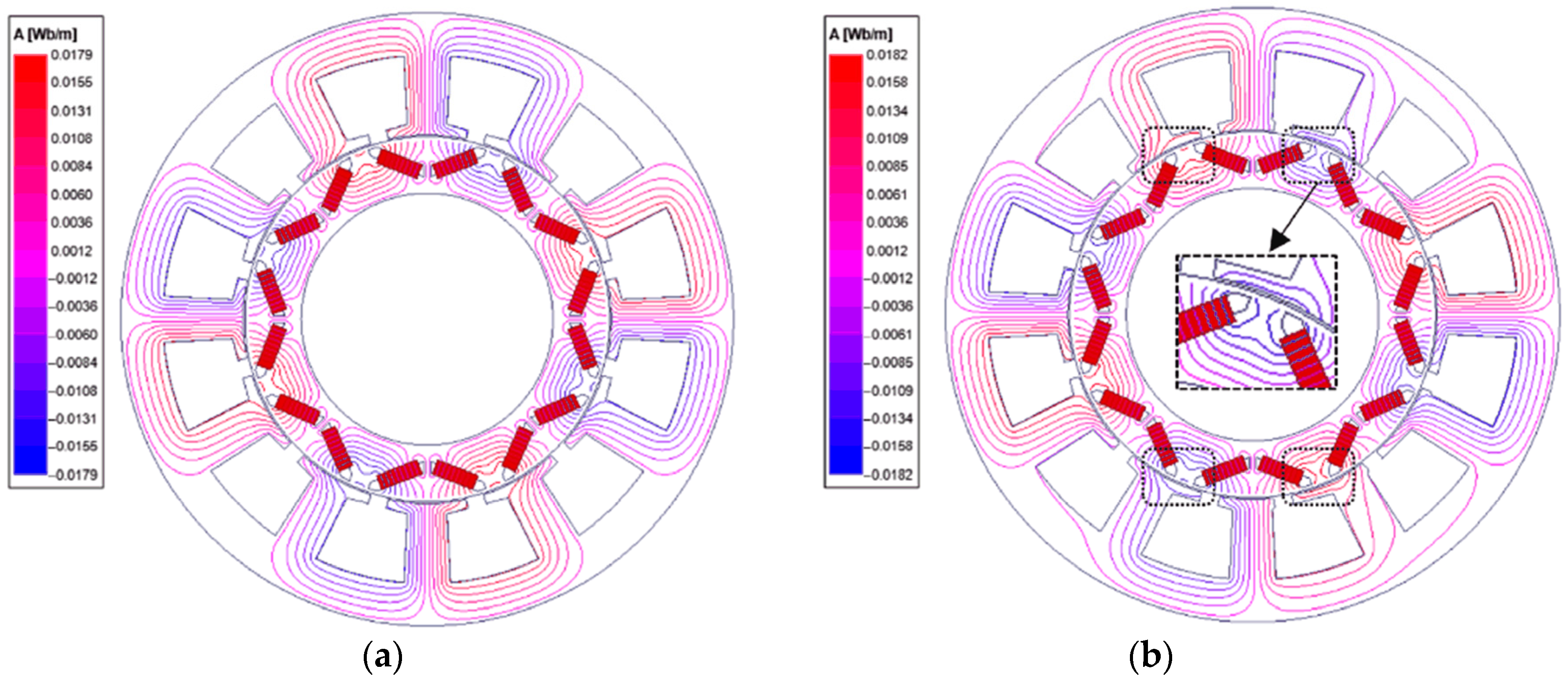
3. Numerical Analysis Case Studies

The proposed method is validated numerically with finite element analysis. Both 8-pole, 12-slot (8P12S) and 10-pole, 12-slot (10P12S) IPMs are used as examples. The parameters are summarized in Table 1. Note that these prototypes are the candidates we designed for a compact-sized sedan car electric driving system. It has the same OD (269.24 mm) and ID (161.9 mm) as a 2004 Toyota Prius traction motor, and similar output peak torque is achieved as that of the 2004 Prius motor. The difference is that the 8P12S or 10P12S concentrated windings are used in our design (instead of the lap windings as used in the Prius 8-pole, 48-slot motor), in order to simplify the manufacturing process (once proven mass producible).

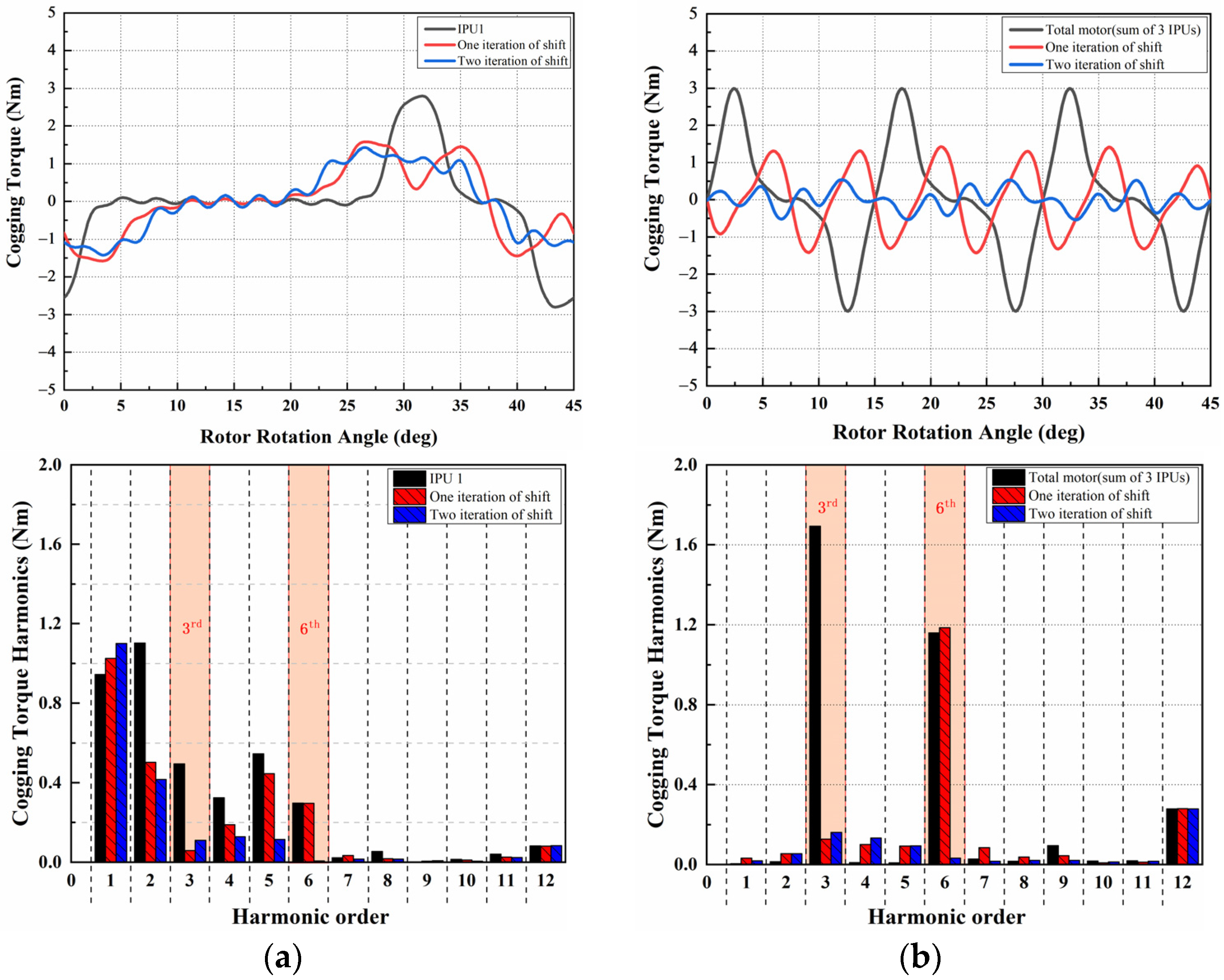
3.1. The Cogging Torque Reduction

The proposed IPU-based slot-opening shift method only needs to design the slot-opening shift for one IPU. Subsequently, after FEA validation using only the slots in this one IPU, the same set of slot-opening shift angles is applied to other IPUs.
Herein, taking IPU 1 of an 8P12S machine ( λ = N c / 2 p = 3 , η = N s / λ = 4 ) as an example, the cogging torque harmonic selective elimination process is illustrated in Figure 6. From (15), it can be obtained that the 8P12S motor has the third, sixth, and ninth cogging torque harmonics cancelled out by the proposed slot-opening shift within an IPU, while the other cogging torque harmonics that exist in each IPU will be inherently cancelled out in the total motor cogging torque.
By two iterations of slot-opening shift in IPU 1, the third and sixth cogging torque harmonic can be minimized. The corresponding shift angles are computed by (10) as shown in Figure 6.
In the first iteration, the third harmonic in the cogging torque is to be cancelled out. The four slot openings are divided into two pairs (1 and 4, 7 and 10). The two slot openings in a pair need to be shifted by (10), i.e., θ shift _ 3 = π / ( 4 3 2 ) = 7.5 . In order to maintain symmetry, each slot opening is shifted in the opposite direction by θ shift _ 3 / 2 .
In the second iteration, the sixth harmonic in the cogging torque is to be cancelled out. The shift angle is computed by (10) as θ shift _ 6 = π / ( 4 6 2 ) = 3.75 . The slot-opening pairs (1 and 4) and (7 and 10) are to be paired up and shifted. In order to maintain symmetry, each slot-opening pair is shifted in the opposite direction by θ shift _ 6 / 2 .
In order to validate the claim in this paper that the proposed IPU-based slot-opening shift method only needs to model the slots in one IPU in FEA validation, Figure 7a,b show the cogging torque FEA pattern the with FFT results of IPU 1 and the total motor, respectively. In Figure 7a,b, the comparison among the original slot openings, one iteration of shift, and two iterations of shift is made. It is noted that the FEA validation of an IPU, as in Figure 7a, will return the cogging torque pattern-containing harmonics that would have been inherently cancelled out in the total motor cogging torque, as in Figure 7b. Specifically, the first and second harmonics, as in Figure 7a, are dominantly large, which explains the fact that the cogging torque of one IPU is not too much smaller than that of the whole motor. Therefore, these harmonic orders can be ignored in the FEA validation process.
Meanwhile, according to (15), the third, sixth, and ninth harmonics of each IPU in Figure 7a are simply summed up in order to obtain the cogging torque harmonics of the total motor. Meanwhile, the reduction of the third, sixth, and ninth harmonics are consistent between the FFT results in Figure 7a,b, as these harmonics, in Figure 7b, are exactly 3 times those in Figure 7a.
From the prior discussion, it is obvious that with the proposed method, one IPU is sufficient for FEA validation of cogging torque reduction. Additionally, instead of making observation on the cogging torque patterns of an IPU, only the FFT results of the harmonics screened out by (15) are to be used to evaluate the cogging torque reduction.
Note that Figure 7b shows the FEA results of the cogging torques of all slots in the motor. Herein, the third harmonic is reduced from 1.69 Nm to 0.16 Nm, and the sixth harmonic is reduced from 1.16 Nm to 0.03 Nm. It is only for comparison purposes here, however. With the IPU-based method, only slots in one IPU are needed during the FEA validation process, as shown in Figure 7a.
For the 10P12S machine ( λ = N c / 2 p = 6 , η = N s / λ = 2 ), the desired shift angle can be also be determined, and the values are shown in Figure 8. According to (10), the desired shift angle is θ shift _ 6 = π / ( 5 6 2 ) = 3 . Herein, the second iteration is not available.

3.2. Back-EMF Compensation

Obviously, for the 8P12S machine, the effectiveness of the cogging torque reduction is also indirectly reflected by the THD of back EMF, which is reduced from 12.62% to 4.72% after the second shift, as in Figure 9a,b. However, the fundamental frequency amplitude of back EMF possesses a slight reduction. Subsequently, the back EMF is compensated by increasing the pole-arc coefficient α p from 0.67 to 0.69. Note that the increase of the pole-arc coefficient is achieved via changing the angle between V-type magnets, without increasing the permanent magnet usage. Furthermore, as shown in Figure 9c, when the pole-arc coefficient is optimized to compensate for the back-EMF reduction, the cogging torque level remains nearly unchanged.
Similarly, the back-EMF compensation after the proposed slot-opening shift is also validated in the 10P12S machine, as shown in Figure 10. Again, the slight back-EMF reduction is well compensated by the pole-arc coefficient optimization, while this compensation does not undermine the effect of the prior cogging torque reduction.

4. Conclusions

In this paper, a new grouping strategy, termed in-phase unit (IPU), in PM machines is introduced, together with the IPU slot-opening shift angle derivation and the selection process of the harmonics to cancel in each IPU. Basically, the same cogging torque patterns produced by the slot openings within an IPU are interleaved, so that the major harmonic components contributing to the total cogging torque are cancelled out. It is further derived and discovered that the harmonic orders of cogging torque between multiple IPUs are either cancelled out or summed up, when all IPUs’ cogging torques are added up. Therefore, these summed up harmonics are screened as the ones to cancel by the proposed slot-opening shift within each IPU. Compared with the existing cogging torque reduction methods that also retain the structure symmetry, the proposed method can realize simplified and rapid FEA verification during cogging torque reduction design iterations, since it only models the slots of one IPU; moreover, back-EMF reduction caused by the slot-opening shift can also be well compensated and no extra harmonic or phase shift is introduced into the back EMF. The proposed methods are validated by numeric analysis of two IPM machine design cases. As an extra benefit, the proposed methods can be applied to SPM or IPM machines with either fractional or integral numbers of slots per pole.

Author Contributions

Conceptualization, L.W.; methodology, L.W. and S.L.; software, L.W.; validation, L.W., S.L., Y.C., and S.W.; formal analysis, L.W. and S.W.; investigation, L.W.; resources, S.L.; writing—original draft preparation, L.W.; writing—review and editing, L.W., S.L., Y.C., and S.W.; visualization, L.W.; supervision, S.L.; project administration, S.L.; funding acquisition, S.L. All authors have read and agreed to the published version of the manuscript.

Funding

This research was funded by the Fundamental Research Funds for the Central Universities, China, under Grant Number 2022CDJXY-007.

Data Availability Statement

Not applicable.

Conflicts of Interest

The authors declare no conflict of interest.

References

  1. Fei, W.; Luk, P.C.K. A New Technique of Cogging Torque Suppression in Direct-Drive Permanent-Magnet Brushless Machines. IEEE Trans. Ind. Appl. 2010, 46, 1332–1340. [Google Scholar] [CrossRef] [Green Version]
  2. Gao, J.; Xiang, Z.M.; Dai, L.T.; Huang, S.D.; Ni, D.C.; Yao, C. Cogging Torque Dynamic Reduction Based on Harmonic Torque Counteract. IEEE Trans. Magn. 2022, 58, 1–5. [Google Scholar] [CrossRef]
  3. Breton, C.; Bartolome, J.; Benito, J.A.; Tassinario, G.; Flotats, I.; Lu, C.W.; Chalmers, B.J. Influence of machine symmetry on reduction of cogging torque in permanent-magnet brushless motors. IEEE Trans. Magn. 2000, 36, 3819–3823. [Google Scholar] [CrossRef]
  4. Bianchi, N.; Bolognani, S. Design techniques for reducing the cogging torque in surface-mounted PM motors. IEEE Trans. Ind. Appl. 2002, 38, 1259–1265. [Google Scholar] [CrossRef]
  5. Qu, C.Y.; Guo, Z.Q.; Hu, Y.Z.; Wang, X.P.; Han, F.X. Multi-Objective Optimization Design of a New Permanent Magnet Synchronous Motor Based on the Taguchi Method. Energies 2022, 15, 7347. [Google Scholar] [CrossRef]
  6. Koh, C.S.; Seol, J.S. New cogging-torque reduction method for brushless permanent-magnet motors. IEEE Trans. Magn. 2003, 39, 3503–3506. [Google Scholar]
  7. Wang, D.H.; Wang, X.H.; Qiao, D.W.; Pei, Y.; Jung, S.Y. Reducing Cogging Torque in Surface-Mounted Permanent-Magnet Motors by Nonuniformly Distributed Teeth Method. IEEE Trans. Magn. 2011, 47, 2231–2239. [Google Scholar] [CrossRef]
  8. Bianchini, C.; Immovilli, F.; Lorenzani, E.; Bellini, A.; Davoli, M. Review of Design Solutions for Internal Permanent-Magnet Machines Cogging Torque Reduction. IEEE Trans. Magn. 2012, 48, 2685–2693. [Google Scholar] [CrossRef]
  9. Ozoglu, Y.; Garip, M.; Mese, E. New pole tip shapes mitigating torque ripple inshort pitched and fully pitched switched reluctance motors. Electr. Power Syst. Res. 2005, 74, 95–103. [Google Scholar] [CrossRef]
  10. Wang, D.H.; Wang, X.H.; Jung, S.Y. Cogging Torque Minimization and Torque Ripple Suppression in Surface-Mounted Permanent Magnet Synchronous Machines Using Different Magnet Widths. IEEE Trans. Magn. 2013, 49, 2295–2298. [Google Scholar] [CrossRef]
  11. Zhang, J.; Cheng, M.; Chen, Z. Optimal design of stator interior permanent magnet machine with minimized cogging torque for wind power application. Energy Convers. Manag. 2008, 49, 2100–2105. [Google Scholar] [CrossRef]
  12. Hasanien, H.M. Torque ripple minimization of permanent magnet synchronous motor using digital observer controller. Energy Convers. Manag. 2010, 51, 98–104. [Google Scholar] [CrossRef]
  13. Caruso, M.; Di Tommaso, A.O.; Miceli, R.; Viola, F. A Cogging Torque Minimization Procedure for Interior Permanent Magnet Synchronous Motors Based on a Progressive Modification of the Rotor Lamination Geometry. Energies 2022, 15, 4956. [Google Scholar] [CrossRef]
  14. Caruso, M.; Di Tommaso, A.O.; Miceli, R.; Schettino, G.; Viola, F. A Cogging Torque Minimization Procedure for IPMSMs based on Different Laminate Geometry. In Proceedings of the 2016 Eleventh International Conference on Ecological Vehicles and Renewable Energies (EVER), Monte Carlo, Monaco, 6–8 April 2016. [Google Scholar]
  15. Ren, W.; Xu, Q.; Li, Q.; Zhou, L.B. Reduction of Cogging Torque and Torque Ripple in Interior PM Machines with Asymmetrical V-Type Rotor Design. IEEE Trans. Magn. 2016, 52, 1–5. [Google Scholar] [CrossRef]
  16. Wan, X.B.; Yang, S.; Li, Y.C.; Shi, Y.; Lou, J.Y. Minimization of Cogging Torque for V-Type IPMSM by the Asymmetric Auxiliary Slots on the Rotor. IEEE Access 2022, 10, 89428–89436. [Google Scholar] [CrossRef]
  17. Kang, G.H.; Son, Y.D.; Kim, G.T.; Hur, J. A Novel Cogging Torque Reduction Method for Interior-Type Permanent-Magnet Motor. IEEE Trans. Ind. Appl. 2009, 45, 161–167. [Google Scholar] [CrossRef]
  18. Gao, J.; Wang, G.; Liu, X.; Zhang, W.J.; Huang, S.D.; Li, H.M. Cogging Torque Reduction by Elementary-Cogging-Unit Shift for Permanent Magnet Machines. IEEE Trans. Magn. 2017, 53, 8208705. [Google Scholar] [CrossRef]
  19. Dosiek, L.; Pillay, P. Cogging torque reduction in permanent magnet machines. IEEE Trans. Ind. Appl. 2007, 43, 1565–1571. [Google Scholar] [CrossRef] [Green Version]
  20. Zhao, J.C.; Wang, J.; Zhou, L.B.; Huang, W.H.; Ma, Y.M.; Zhang, Z.W. Cogging Torque Reduction by Stepped Slot-Opening Shift for Interior Permanent Magnet Motors. In Proceedings of the 2019 22nd International Conference on Electrical Machines and Systems (ICEMS), Harbin, China, 11–14 August 2019. [Google Scholar]
  21. Hwang, S.M.; Eom, J.B.; Jung, Y.H.; Lee, D.W.; Kang, B.S. Various design techniques to reduce cogging torque by controlling energy variation in permanent magnet motors. IEEE Trans. Magn. 2001, 37, 2806–2809. [Google Scholar] [CrossRef]
  22. Hwang, S.M.; Eom, J.B.; Hwang, G.B.; Jeong, W.B.; Jung, Y.H. Cogging torque and acoustic noise reduction in permanent magnet motors by teeth pairing. IEEE Trans. Magn. 2000, 36, 3144–3146. [Google Scholar] [CrossRef] [Green Version]
  23. Abbaszadeh, K.; Jafari, M. Optimizing cogging torque reduction in slot opening shift method for BLDC motor by RSM. In Proceedings of the 2011 2nd Power Electronics, Drive Systems and Technologies Conference, Tehran, Iran, 16–17 February 2011. [Google Scholar]
  24. Liu, T.; Huang, S.D.; Gao, J.; Lu, K.Y. Cogging Torque Reduction by Slot-Opening Shift for Permanent Magnet Machines. IEEE Trans. Magn. 2013, 49, 4028–4031. [Google Scholar] [CrossRef]
  25. Hanselman, D. Brushless Permanent-Magnet Motor Design; McGraw: New York, NY, USA, 1994. [Google Scholar]
  26. Zhu, Z.Q.; Ruangsinchaiwanich, S.; Schofield, N.; Howe, D. Reduction of cogging torque in interior-magnet brushless machines. IEEE Trans. Magn. 2003, 39, 3238–3240. [Google Scholar] [CrossRef] [Green Version]
  27. Qu, R.H.; Lipo, T.A. Analysis and modeling of air-gap and zigzag leakage fluxes in a surface-mounted permanent-magnet machine. IEEE Trans. Ind. Appl. 2004, 40, 121–127. [Google Scholar] [CrossRef]
Figure 1. The proposed IPU within an IPM machine.
Mathematics 11 01735 g001
Figure 2. The cogging torque generated by each stator slot opening of an 8-pole, 12-slot machine.
Mathematics 11 01735 g002
Figure 3. The iteration process of cogging torque harmonic cancellation within an IPU.
Mathematics 11 01735 g003
Figure 4. The summary of the proposed cogging torque reduction process.
Mathematics 11 01735 g004
Figure 5. The no-load magnetic field distribution for IPM machine: (a) the normal slot opening, (b) the IPU slot-opening shift.
Mathematics 11 01735 g005
Figure 6. The slot-opening shift angle in an IPU (8P12S).
Mathematics 11 01735 g006
Figure 7. The cogging torque FEA pattern with FFT results: (a) the IPU1 and (b) the total motor.
Mathematics 11 01735 g007
Figure 8. The slot-opening shift angle in an IPU (10P12S).
Mathematics 11 01735 g008
Figure 9. Back-EMF compensation of the 8P12S machine: (a) waveforms, (b) FFT, and (c) cogging torque after back-EMF compensation.
Mathematics 11 01735 g009
Figure 10. Back-EMF compensation of the 10P12S machine: (a) waveforms, (b) FFT, and (c) cogging torque after back-EMF compensation.
Mathematics 11 01735 g010
Table 1. Main design parameters of the selected machines.
Parameters8P12S10P12S
Outer diameter of stator (mm), D 1 269.24269.24
Inner diameter of stator (mm), D i 1 161.9161.9
Outer diameter of rotor (mm), D 2 160.4160.4
Inner diameter of rotor (mm), D i 2 110.64110.64
Machine active length (mm), L e f 83.8283.82
Rated/peak power (kW) @1200 rpm, P 33/5033/50
Rated/peak torque (Nm) with MTPA, T 264/400264/400
Rated/peak current RMS vaule (A), I 127/212127/212
Maximum speed (r/min), n r 60006000
Air-gap length (mm), δ 0.750.75
Magnet width (mm), ω m 1914
Magnet thickness (mm), h m 6.486.48
Pole-arc coefficient, α p 0.670.58
Slot-opening coefficient, α s 0.190.09
Magnet remanence (T), B r 1.1911.191
Magnet relative permeability, μ r 1.031.03
Disclaimer/Publisher’s Note: The statements, opinions and data contained in all publications are solely those of the individual author(s) and contributor(s) and not of MDPI and/or the editor(s). MDPI and/or the editor(s) disclaim responsibility for any injury to people or property resulting from any ideas, methods, instructions or products referred to in the content.

