


Refined Design and Optimization of Underground Medium and Long Hole Blasting Parameters—A Case Study of the Gaofeng Mine

1
School of Resources and Safety Engineering, Central South University, Changsha 410083, China
2
Hunan Provincial Key Laboratory of Resources Exploitation and Hazard Control for Deep Metal Mines, Central South University, Changsha 410083, China
3
Guangxi Gaofeng Mining Co., Ltd., Nandan 547051, China
*
Author to whom correspondence should be addressed.
Mathematics 2023, 11(7), 1612; https://doi.org/10.3390/math11071612
Submission received: 22 February 2023
/
Revised: 18 March 2023
/
Accepted: 22 March 2023
/
Published: 27 March 2023
(This article belongs to the Special Issue Advances in Computational Intelligence in Geotechnical and Geological Engineering)
Abstract
:Previously conducted studies have established that the rationality of the parameters of medium-deep hole blasting is one of the main factors affecting the blasting effect. To solve the problem of the parameter design and optimization design of medium-deep hole blasting in underground mines, a method of parameter design and the optimization of medium-deep hole blasting based on the blasting crater tests and numerical simulation analyses has been proposed in this study. Based on the background of deep underground mining in Gaofeng Mine, a two-hole blasting model has been established, and the blasting parameters are simulated and analyzed by the damage stress variation of the two-hole model. During the study, the initial values of blasting parameters were first obtained from the field blasting crater test, then the blasting parameters were optimized and analyzed by LS-DYNA software, and finally, the optimization scheme was demonstrated by the corresponding blasting test. The results of the field test showed that the design method of integrated blast crater test and numerical simulation analysis can effectively optimize the design of medium-deep hole blasting parameters and improve the blasting effect to a large extent. This study also provides an effective design system for the design of deep hole blasting parameters in similar mines.
1. Introduction
In mining engineering, medium-deep hole blasting has been widely used in mining. Compared with shallow hole blasting, medium-deep hole blasting has a larger one-time blasting amount, more ore caving, low explosive consumption, and high production efficiency. Moreover, the mining cycle is reduced and the production auxiliary system is simplified [1,2].
It has been proved that reasonable blasting parameters are core to ensuring the quality of medium-deep hole blasting, and the design and optimization of blasting parameters are of great significance to mining [3,4]. In recent years, a lot of work has been carried out to determine the parameters of blasting and the impact of disturbances on the rock mass. Stanković et al. [5] have studied the effect of vibration monitoring instruments positioning on burst vibration, and give recommendations for vibration monitoring instruments positioning during test blasts on any new site, to optimize charge weight per delay for future blasting works without increasing the possibility of damaging surrounding structures. Sołtys [6] has used a matching pursuit algorithm to assess the impact of blasting in open-pit mines on the surrounding area and has proved that by taking into account frequency changes over time, vibration analysis can help make much more profound and reliable predictions in this field.
In traditional blasting parameter optimization and design, mines mainly design blasting parameters based on empirical formulas and adjust blasting parameters according to geological conditions and other conditions. Himanshu et al. [7] have designed the blasting parameters for Ring holes on underground slopes based on empirical formulas and projected the rock fragmentation effect using the Kuz-Ram model, which has also achieved some success. However, the empirical formula method is simple to operate, but the method is subjective to human influence, lacks the corresponding theoretical support, and the effect of optimization also has certain limitations [8]. Nowadays, blasting projects have higher requirements in terms of fragmentation, explosive energy control, blasting efficiency, and safety and environmental protection, and traditional methods can no longer achieve the requirements, so a fine blasting theory has gradually been developed that is more compatible with modern blasting requirements [9].
Up to now, the refined blasting design and optimization system have been applied to more and more blasting fields. Pal et al. [10] have conducted a systematic study on drilling, blasting parameters, gas hazards, strata behavior, and ground vibration to solve the design problem of underground-induced blasting, providing a research idea for a similar blast design. Widodo et al. [11] have analyzed the overbreak and underbreak of each scheme during field blasting, and obtained the optimal scheme under different explosives and blasting parameters, which effectively improved the blasting effect. These methods have achieved good results, but there are some shortcomings that do not reflect the optimization work of blasting parameters. Instead, the common method used in field blasting test research is to design and optimize blasting parameters based on blast crater tests. Jeon et al. [12] have conducted a blasting crater test in underground mines and calculated the minimum explosive quantity of rocks according to the characteristics of rock blasting damage. This method effectively improved the blasting charge. Zhang et al. [13] have conducted blast crater tests under different stress load conditions and proposed a design method for blast parameters considering field stresses based on the test results. The design method based on field blasting tests makes the blasting parameters closer to the actual conditions of the mine, but the method is also subjectively influenced by humans and may produce some errors. Thus, based on the blasting crater test, an intelligent algorithm-based parameter optimization method is proposed. Monjezi et al. [14] have used a genetic algorithm to optimize blasting parameters, which effectively reduced blasting fly rock generation. Dehghani et al. [15] have optimized blasting parameters by a cuckoo optimization algorithm, which effectively reduced blasting fly rock. Saghatforoush et al. [16] have used artificial neural networks for the prediction of blasting fly rock and achieved optimization of blasting parameters by the ant colony optimization algorithm. Bastami et al. [17] have used gene expression programming and particle swarm optimization to predict and optimize blasting costs and obtained optimized blasting parameter designs through blasting cost optimization analysis, which effectively improved blasting fragmentation and reduced the adverse consequences of the blasting process. Sirjani [18] has used the artificial neural network (ANN) model and statistical models to study the anti-rupture in the blasting process. According to the prediction and analysis of the model, the optimal blast pattern design parameters are determined.
These algorithms have greatly improved the rationality of blasting parameters, but the optimization scheme based on intelligent algorithm still has problems such as incomplete analysis and evaluation of the influence factors of blasting parameters, and the intelligent algorithm only focuses on the data itself without linking the relationship between the data, Therefore, the analysis system of blasting parameter optimization based on numerical simulation was gradually formed in the subsequent research [19]. Huang et al. [20] have used PFC2D to optimize blasting parameters and obtained the optimal blasting parameters by analyzing the simulated blasting effects and stress values at monitoring points under different parameters. Jiang et al. [21] have analyzed the damage characteristics of VCR blasting surrounding rocks using FLAC3D and derived the relationship between explosive quantity and damage radius of surrounding rocks, which provides a theoretical basis for optimizing blasting parameters. Mejía et al. [22] have simulated the blasting of different shaped explosive charges using CFD and ANSYS, and obtained Characterization of Blast Wave Parameters of Shaped Charges through the analysis of shock wave stresses to provide support for the design of charging parameters of poly energy charges. The blasting can be simulated by FLAC3D, PFC2D, and other software, but LS-DYNA is the most widely used software in research and practical application. LS-DYNA can clearly show the formation process of fracture area and the development of damage fracture in rock during blasting and can also monitor the stress at key points during the simulation process [23,24,25]. Huo et al. [26] have analyzed the rock damage of lateral blasting using LS-DYNA and improved the blasting parameters based on the simulation results. Sun et al. [27] have used LS-DYNA software to carry out numerical simulation analysis on the influence of different factors on the blasting presplitting process and have determined the best parameters for blasting drilling. The practice has proven that LS-DYNA software can easily and accurately simulate the process of blasting and rock breaking, and now it has become a common analysis tool in blasting research. However, the optimization of blasting parameters based on numerical simulation greatly improves the rationality of the parameters, but the simulation requires certain initial parameter data, and most of the initial parameter data in the study come from empirical design, lacking the corresponding experimental basis, and to a certain extent, it is also detached from the actual situation of the mine site.
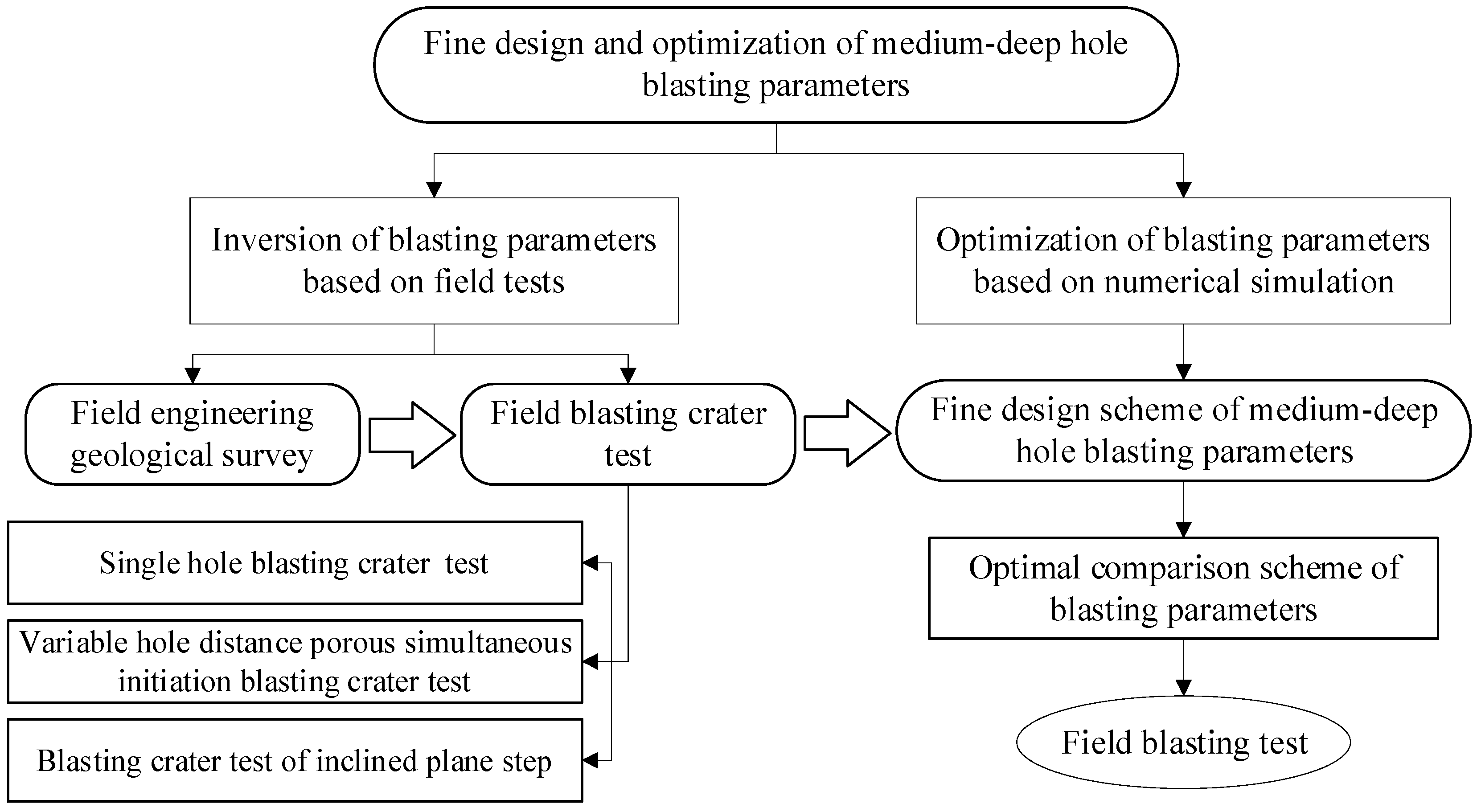
Analyzing the above, it can be noted that the design of medium-deep hole blasting parameters is a very topical issue. Therefore, the purpose of this study is to obtain reasonable parameters for medium-deep hole blasting underground in the Gaofeng Mine, and to achieve this, it is necessary to solve the following tasks: (1) carry out field engineering geological investigation and field blasting crater test; (2) carry out a numerical simulation to optimize blasting parameters; (3) and carry out field blasting tests and analyze blasting results. The specific blasting parameter optimization design process is demonstrated in Figure 1.
2. Inversion of Medium-Deep Hole Blasting Parameters Based on Blasting Crater Test
This blasting crater test includes a single-hole blasting crater test, variable hole distance porous simultaneous initiation blasting crater test, and blasting crater test of the inclined plane step. The blasting crater test is based on the Livingston blasting crater theory, also known as the energy balance theory. According to Livingston, when a spherical charge explodes inside the rock, the degree of deformation and destruction of the rock depends largely on the amount of energy that passes through it. Livingston studied the effect of changing the embedment depth of the charge on rock failure with the weight of the charge unchanged and proposed that the relationship between the critical embedment depth of the charge Le and the charge quantity Q can be expressed by the following formula [28]:
where Le is the critical burial depth, E is the strain energy coefficient, and E is constant for specific rocks and explosives. Q is the weight of the globular package.
Livingston’s blasting crater theory is based on the ball charge test. The charge quantity for the blasting of spherical charge is calculated according to the law of cubic root similarity. That is, when the same explosive explodes in the same kind of rock, each parameter of the blasting crater with a certain effect is exploded when the amount of explosive is Q0, and each parameter of the other blasting crater when the amount of explosive is changed to Q1 and meets the cubic formula [28]:
where subscriptions 0 and 1 represent the original blasting model and derived model, respectively. Lj is the best burying depth of explosives for blasting crater tests. Qj is the best charge quantity for the blasting crater test. Rj is the best radius of the blasting crater. Vj is the optimum volume of the blasting crater.
According to the basic principle that the shape of the blasting crater is similar under different charge amounts and the optimum consumption per unit is unchanged, the parameter relation of different blasting craters under different cylindrical charge conditions can be obtained by replacing the buried depth of spherical charge with the depth of blasting hole. Finally, according to the blasting similarity principle, the blasting parameters of medium-deep holes under the same geological conditions can be derived from the blasting parameters of spherical charge [29].
2.1. Engineering Background
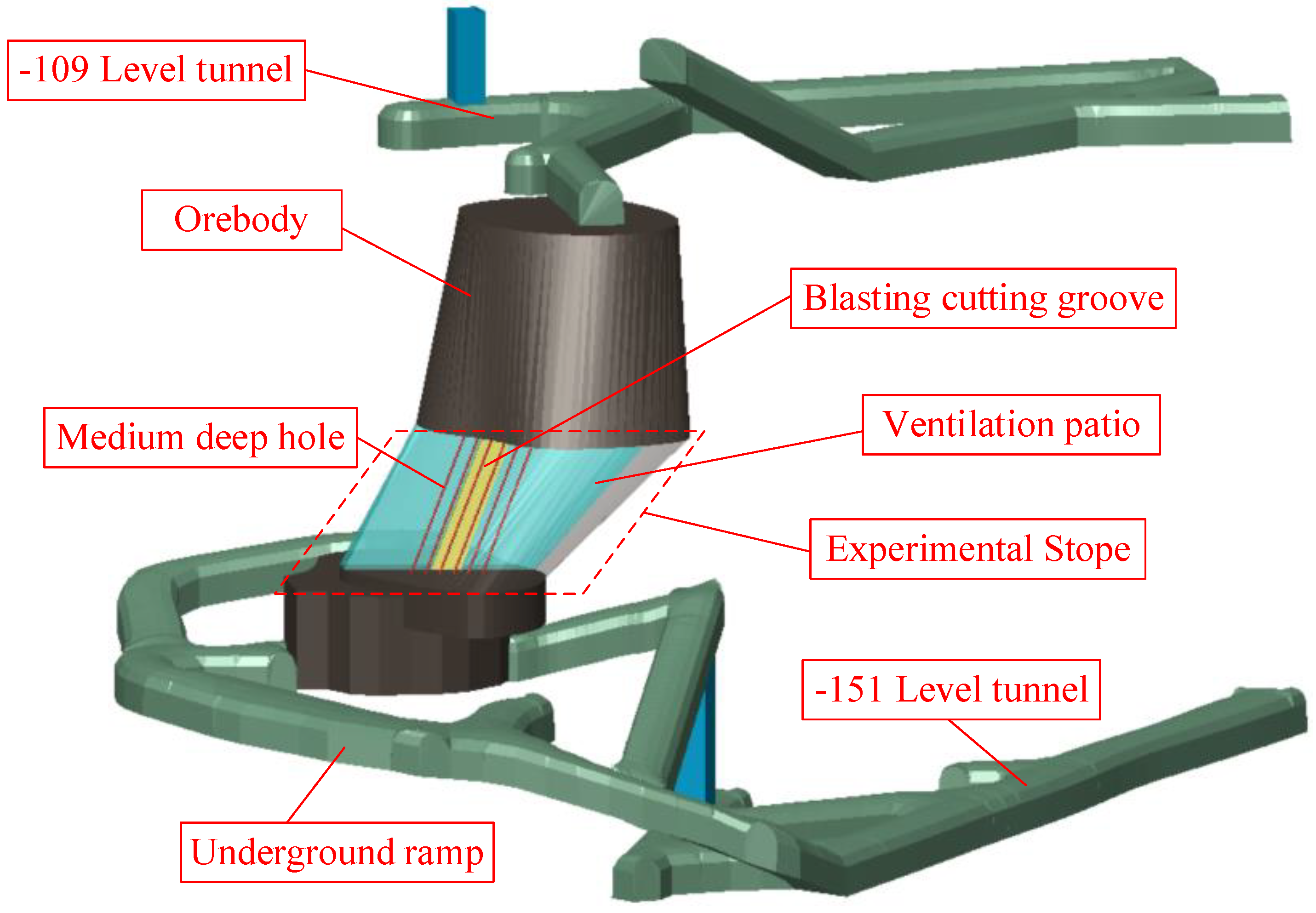
The average thickness of the ore body at the test mining site of the medium-deep hole blasting drop at the Guangxi Summit Mine is about 10 m. The ore body elevation is −110 m~−134 m, the length of the ore body is about 21 m, the middle thickness is thin at both ends, and it is an independent small orebody. Minerals and surrounding rocks are more moderately stable than those affected by historical excavation. Depending on the shape distribution of the ore body and mining equipment, mining is divided into upper and lower parts, and a blasting network is used for ore falling. In the design, the depth of the deep hole is 12 m and the diameter of the hole is 65 mm. The details of the ore body are demonstrated in Figure 2.
The deposit type of the Gao Feng mine is a cassiterite-sulfide type deposit, with a clear boundary between the ore body and the surrounding rocks. The underground ore is mainly cassiterite, with a saturated compressive strength of 80~100 MPa, and the ore is dense and massive with good solidity. The rock quality is above medium, and most of the rock body is above medium integrity. The enclosing rocks are mainly biogenic reef tuffs with a saturated compressive strength of 58 to 90.1 MPa. For hard rocks, the rock quality is above medium, and the enclosing rocks are mostly of good integrity and high compressive strength.
Medium-deep hole blasting has been attempted in the Gaofeng Mine. Due to various factors, it results in a high block rate and an unsatisfactory blasting effect. Because of the above problems, this test carries out a fine design of medium-deep hole blasting parameters through field tests and numerical simulation methods to improve the blasting effect
2.2. Blasting Crater Test Scheme
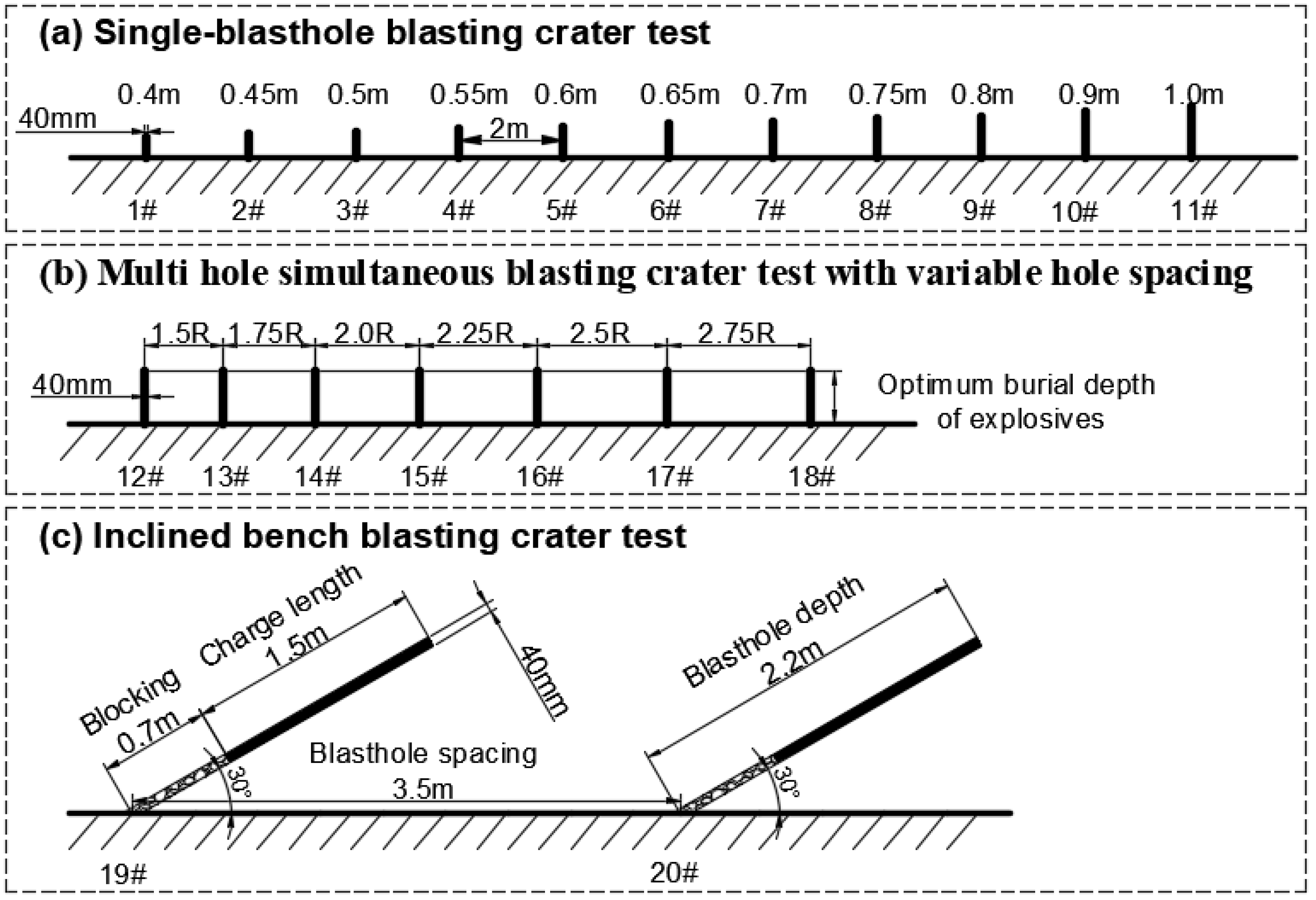
Firstly, through the single-hole blasting crater tests, the optimum buried depth of the charge center, the volume, and the radius of the blasting crater are determined under the condition of the single hole. Secondly, based on the parameters of single-hole series blasting crater tests, the variable-spacing multi-hole and same-stage blasting crater tests are carried out, and the optimum hole spacing and explosive consumption under this test condition are deduced. Finally, the minimum resistance line parameters of blasting are determined by the crater test of inclined step blasting. According to the blasting similarity theory, the optimum range of medium-deep hole blasting parameters can be calculated. There are 20 holes with 40 mm diameters in this series of hole crater tests. The specific arrangement of the test holes is demonstrated in Figure 3.
2.3. Analysis of Experimental Results
As demonstrated in Figure 4, the field test data collected are processed by CAD, 3D MINE, and MATLAB. The final series of test results are yielded in Table 1.
According to the blasting similarity theory, the average charge required to break a rock per cubic meter is a fixed value for a given rock. In cylindrical charge, when the charge parameter is changed to the charge quantity per unit length, the proportional relation changes from cubic relation to square relation. That is, the blasting similarity relationship can be expressed by the following formula [30]:
where and are the linear parameters of the bore corresponding to the cylindrical charge blasting model and the blasting test model, such as resistance line, hole bottom distance, etc. and are the charge quantities of the cylindrical charge blasting model and the blasting test model, respectively.
Therefore, based on the above analysis, when the hole diameter is 65 mm, the parameters of medium-deep hole blasting are calculated as follows:
- (1)
- Unit loading q = 1.58 kg/m.
- (2)
- Hole distance a = 1.6 m.
- (3)
- Resistance line b = 1.4 m.
3. Blasting Parameter Optimization Based on Numerical Simulation
3.1. Model Building
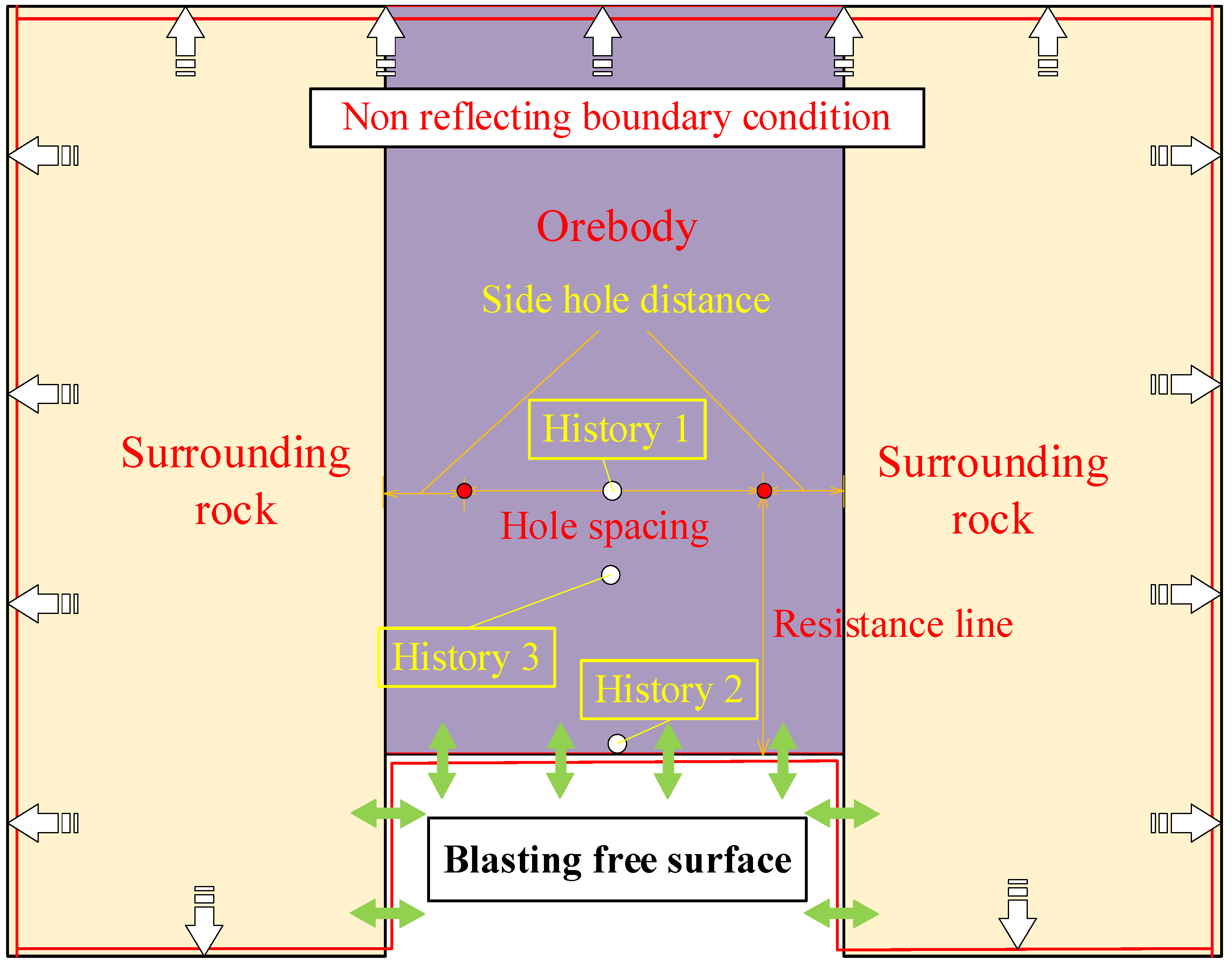
LS-DYNA nonlinear finite element software was used to optimize the parameters obtained from the blasting test. At present, the blasting method of row by row is mainly adopted for medium-deep holes under the Gaofeng Mine, and there are only two free planes in each row, and there is a certain stage difference between front and back blasting. Therefore, in order to facilitate more convenient simulation analysis and be more suitable for the actual mine production, the model is simplified to analyze the first-row blasting problem, and a double-hole blasting model is established. At the same time, since the hole depth was much larger than the aperture in the test, the numerical model was simplified into a two-dimensional calculation model without affecting the accuracy of the simulation [31]. In the simulation, the fluid-structure coupling calculation method was used for modeling, the Lagrange algorithm model was set for rock, the Euler algorithm model for explosive, and the 1/2 symmetric grid model was adopted. Since the blasting model was based on the plane stress problem of the infinite body, in addition to the free plane of the cutting groove, no reflection boundary conditions are set in the other three directions, and normal constraints are set in the Z direction [32]. The middle part of the model is the ore area, and the two sides are the surrounding rock area to simulate the blasting and crushing environment of the ore under the surrounding rock clip production. The front area of the model is the free surface area, which is used to simulate the free surface formed by the blasting and cutting groove. The specific model settings are yielded in Figure 5.
3.2. Material Parameter
3.2.1. Rock Material Model
RHT (Riedel-Hiermaier-Thoma) constitutive model was selected for rock materials, which was proposed by Riedel, Hiermaier, and Thoma on the basis of the HJC (Holmquist-Johnson-Cook) model. The influence of the third invariant of the deviatoric stress tensor J3 on the shape of the failure surface was introduced to determine the strain type and stress state of the material, and the strength of the material was elucidated by the yield surface, failure surface, and residual strength surface [33,34]. This model is also used to simulate damage constitutive models of rock impact and blasting.
There are many parameters of the RHT model, including default parameters, physical and mechanical property parameters, calculation and derivation parameters, equation-of-state parameters, damage parameters, and strength-related parameters. In the early stage of this test, relevant indoor rock mechanics tests have been completed, and specific mechanical property parameters have been obtained. By referring to relevant literature and similar model parameter design experience [35,36,37] and determining the values of all parameters of the model, as yielded in Table 2.
3.2.2. Explosive Material Model
During simulation, the HIGH-EXPLOSIVE model in the LS-DYNA material library is used to describe the constitutive relation of explosive, and the Jones-Wilkins-Lee (JWL) equation of state (EOS) is used to describe the relationship between explosive volume expansion and explosive pressure. This equation can fully reflect the stress variation process of explosives in the process of the explosion and is widely used in simulated blasting models [38,39,40].
3.3. Modeling Scheme
The corresponding simulation scheme is set up according to the initial blasting parameters obtained from the field blasting crater test. During the simulation, the blasting schemes with different resistance lines are first compared and analyzed, and the parameters of the best resistance lines are determined. Then, the blasting schemes with different hole distances are simulated and analyzed, so as to attain the best blasting hole network parameter scheme. In addition, according to the related research, increasing the hole density coefficient can effectively improve in medium-deep hole blasting effect and decrease the rate of large blocks, but the first row of the blast hole density coefficient should not be too big, the first row of the best hole density coefficient of between 0.9 and 1.1 [41]. Therefore, in order to avoid invalid pore mesh parameter schemes and simplify the workload of numerical simulation, when setting relevant pore mesh parameter schemes, the shot hole density coefficient of the simulation scheme should be kept within the range of the best shot hole density coefficient.
3.4. Analysis of Numerical Simulation Results
3.4.1. Blasting Rock-Breaking Analysis
In numerical simulation blasting, the rock is generally considered to be broken if the damage coefficient of the rock is above 0.6 [26]. Therefore, the rock breakage in the blasting process can be demonstrated in a more comprehensive way according to the cloud map of rock damage fissure changes. According to modern blasting rock-breaking theory, rock destruction is mainly formed by the combined action of explosion shock wave and detonation gas [42]. According to the blasting rock-breaking theory, taking the initial blasting parameter model of 1.6m×1.4m as the research object, the blasting rock-breaking process is divided into 4 stages, as yielded in Figure 6.
The first stage is the compression stage, as yielded in Figure 6a. Under the action of a high-pressure shock wave, the surrounding rock near the gun hole is compacted to form a compressible crushing zone. Since the crushing zone absorbs most of the energy of the blasting shock wave, the explosion shock wave rapidly attenuates into stress waves. Although the strength of the stress wave is not enough to compress the rock, the outer rock of the crushing zone is still subjected to strong radial compression, and radial cracks are generated to form the cracked zone.
The second stage is the damage stage, as yielded in Figure 6b. This stage is the main rock-breaking stage. The stress waves between the two holes begin to superposition, and the cracks are connected, resulting in rock failure. Moreover, when the stress waves are transmitted to the free surface, reflections are generated, and the compressive stress waves become tensile stress waves, resulting in large area tensile failure of the free surface rock under the action of reflected tensile force.
The third stage is the expansion stage, as yielded in Figure 6c. At this stage, with the continuous action of stress waves and blasting gas, the cracks continue to expand, resulting in further rock damage.
The fourth stage is the end stage, as yielded in Figure 6d. At this stage, the stress wave and blasting gas have attenuated to the point that the rock cannot be damaged and the crack cannot continue to expand.
Through the simulation of the rock-breaking process of blasting, it can be seen that the position of the free surface during blasting is mainly caused by the tensile failure caused by the reflection of the tensile stress wave. The damage distribution area of this part of the rock is large, and the rock-breaking condition is relatively good. However, the rock between the holes is mainly caused by the mutual penetration of radial cracks caused by the blasting shock wave. This part of the damage mainly depends on the combined action of radial compression stress and detonation gas. The damaged area is small, and the crushing effect is worse than that of the free surface.
3.4.2. Influence of Resistance Line on Blasting Effect
According to the above-simulated rock-breaking analysis process, the effect of the damage fracture program and stress monitoring curve on different resistance lines is simulated and analyzed. The hole spacing was set at 1.6 m, and the resistance lines were set at 1.5 m, 1.4 m, and 1.3 m, respectively. The simulated damage results of each scheme are yielded in Figure 7.
It can be seen from Figure 7 that as the resistance line decreases, the crushing effect of the free surface rock body is also better, but the analysis from Figure 7c demonstrated that when the free surface resistance line is smallest, the rock crushing degree between the gun holes is poorer, which indicates that not the smaller the resistance line, the better the overall crushing effect. This may be due to the resistance line being small or the free-face reverse tensile stress wave having prematurely destroyed the free-face rock, resulting in the premature release of blast gas from the free face, thus affecting the effect of rock fragmentation between the shell holes. Therefore, from the perspective of the development of damage crushing, when the resistance line is 1.3 m, the simulation obtained the best damage-crushing effect of the free face, and when the resistance line is 1.4 m, the overall damage-crushing effect of blasting is the best.
In order to compare and analyze the damage effects of each scheme more accurately, corresponding stress monitoring points (history one and history two) are set in the middle of the hole and in the middle of the free surface during the simulation process. The blasting damage of rock mass between the free surface and the hole can be judged by the stress of the blasting shock wave. The shock wave monitored by each scheme is yielded in Figure 8.
Figure 8 demonstrated that around 0.4 ms after blasting, the blasting shock wave is transmitted to the free surface and rapidly increases to the maximum value. Then, the reflection begins to decrease to form a tensile stress wave, which gradually decays to 0. The tensile stress wave also fluctuates up and down due to the interaction between the blast wave in the gun hole. By comparing and analyzing the stress monitored by the free surface, it can be seen that when the hole distance is fixed at 1.6 m, the smaller the resistance line, the longer the action time of the free surface tensile stress wave, and the more uniform the change. According to the blasting mechanism, the damage to the free surface rock is mainly caused by reflecting the tensile stress wave. Therefore, from the perspective of the tensile stress wave, the smaller the resistance line is. The damage and crushing effect of free-face rock are also better.
According to the stress distribution monitoring at the intermediate point of the hole, it can be seen that at about 0.3 ms, the blasting shock wave is transmitted to the intermediate point of the hole and quickly reaches the maximum value, about 70 MPa. Although the stress value of the shock wave at this time is less than the compressive strength of the rock, which is not enough to damage the rock, according to the analysis of blasting rock breakage, blasting rock breakage is not a single impact failure but rather the combined action of shock waves and detonation gas. Therefore, it can be seen from the damage fracture diagram that, although a shock wave is not enough to damage rock, the rock still suffers damage and failure under comprehensive action conditions. It can be seen from the analysis of the graph that the cracks between the two holes are free planes of each other to a certain extent, so a certain reflected tensile stress also appears in the monitoring stress. However, the free plane conditions formed by the holes are limited, and the tensile stress generated between the holes is small.
3.4.3. Analysis of Hole Distance Simulation Results
According to the above simulation results, under the condition that the optimal resistance line is 1.4 m, the hole spacing is set at 1.6 m, 1.5 m, and 1.4 m, respectively, to conduct the simulation test. In order to fully verify the influence of the resistance line, another 3 models with 1.6 m, 1.5 m, and 1.4 m hole spacing were set under the condition of the 1.3 m resistance line. The simulated damage results of each scheme are yielded in Figure 9.
As can be seen from Figure 9, when the resistance line is 1.4 m, the damaging effect of free-face rock in Scheme 2 is slightly worse than that in Scheme 4 and Scheme 5, but the damage condition is also in a good state. According to the damaging effect of the rock between the holes, the damaging effect of Scheme 4 is better than that of Scheme 2 and Scheme 5. It is analyzed that the interaction between the holes may be weakened when the hole distance is too large. However, when the hole distance is small, the shock wave forms the penetrating fissure on the line between holes too early, resulting in the explosion of energy escaping in advance. Therefore, when the resistance line is 1.4 m, the rock blasting damage effect is the best when the hole distance in Scheme 4 is set at 1.5 m.
Compared with the analysis of each scheme in Figure 9, it can be seen that when the resistance line is 1.3 m, the free surface blasting damage effect of each scheme is better than that of the scheme with the resistance line being 1.4 m. Meanwhile, the rock damage and breakage effect between the free surface and the hole is better as the hole distance is smaller. To a certain extent, it promotes the damage and crushing effect of rock between holes and free face. Therefore, when the resistance line is 1.3 m, the rock damage effect is the best when the hole spacing in Scheme 7 is 1.4 m.
Comprehensive comparative analysis of Scheme 4 and Scheme 7, although the 2 schemes are the best schemes at the resistance line of 1.4 m and 1.3 m, respectively, there are still some differences, as can be seen from Figure 9b,f, there is a certain weak damage zone between the gun hole and the free surface damage for both schemes (red circled part in the figure), and obviously, the comparison can be seen that compared with Scheme 4, the weak damage zone area of Scheme 7 is smaller, so the overall blast damage effect of Scheme 7 is better from the blast damage point of view.
In order to determine the blasting effect of the two schemes in the weak damage area more accurately, the corresponding blasting shock wave monitoring point (history 3) is established in the weak fracture area in the simulation, and the blasting damage situation is judged by analyzing the shock wave stress there. The specific distribution of the shock wave is yielded in Figure 10.
It can be seen from Figure 10, the pressure of the blasting shock wave rapidly increases to the maximum value of about 60 MPa at 0.4 ms after detonation, and the maximum pressure value of Scheme 7 is slightly larger than Scheme 4, and then decreases rapidly. Affected by the free surface reflected tensile stress wave, it fluctuates up and down to a certain extent. Some tensile stress even appears in Scheme 7 at 1.8 m. The reason may be that Scheme 7 is more strongly influenced by the free surface reflection tensile stress, which leads to the rapid reduction of compressive stress. From this aspect, it can also be demonstrated that, under the condition that the total blasting energy remains unchanged, the reverse tensile effect generated by Scheme 7 is stronger, and the tensile force transmitted to the weak crushing zone is also larger. Therefore, it can be said that the damage-crushing effect of Scheme 7 in the weak crushing zone is better than that of Scheme 4.
Based on the above analysis, it can be seen from the blasting damage and stress distribution of Scheme 4 and Scheme 7 that the optimal hole mesh parameter scheme should be Scheme 7: 1.4 m × 1.3 m.
4. Field Blasting Test
To further verify the reliability of the theoretical analysis and numerical simulation test results, the optimal Scheme 7 obtained by numerical simulation and the initial Scheme 2 obtained by blasting crater test are selected for the field blasting test. Two rows of holes were arranged in each scheme, and parallel medium-deep holes were arranged in the middle of the rear plate. To better control the footplate boundary, fan-shaped holes were set near the footplate boundary. To avoid excessive concentration of explosives, a cross-charging structure was adopted in the fan-shaped holes. The hole layout is yielded in Figure 11.
The site blasting situation is yielded in Figure 12. According to the analysis of the field blasting effect, most of the blasting fragmentation of Option 2 obtained by the blast crater test are more uniform, but local blasting chunks are still generated, as yielded in Figure 12a. However, in Scheme 7, which is obtained by numerical simulation optimization, there are almost no blasting chunks after blasting. The blasting fragmentation is more uniform on the whole, and the blasting effect is better than Scheme 2, as yielded in Figure 12b.
Comparing the blasting results of the two schemes, Scheme 2 obtained by the blast crater test produced some blast chunks, while the optimized hole network parameters achieved a better crushing result. According to the numerical simulation results, the reasons for the large blast chunks are largely due to the weakening of the reverse tensile stress wave caused by the large resistance line, and the large hole network parameters also mean that more rock volume needs to be crushed per unit of explosive, thus leading to insufficient crushing. The numerical simulation results also show that the blast fragmentation in the hole spacing direction is the same for Scheme 2 and Scheme 7, while there is a large difference in the weak fragmentation zone in the resistance line direction, so it can be indicated that the blasting chunks at the site may originate from the weak fragmentation zone.
Through the field blasting test, it is proved that the parameters of medium-deep hole blasting based on the blasting crater test cannot accurately represent the optimal parameter scheme, and it is also proved that the combination of the blasting crater test and numerical simulation method can effectively carry out fine design and optimization of medium-deep hole blasting parameters.
5. Discussion
The design and optimization of blasting parameters are still the key issues limiting the application and development of medium-deep blasting. Some studies use the blast crater test to design the parameters of medium-deep hole blasting, the test results of this method can better reflect the actual situation of the mine site, but it is easily be affected by human subjective factors during data collection, and the integrity of the test site surrounding rock is required by the blast crater test, so this method does not accurately obtain the optimal parameter scheme. Some studies have also used numerical simulations to optimize blasting parameters, and this method has greatly improved the rationality of the blasting parameter design. The analysis of blasting damage by numerical simulation is also more accurate, but numerical simulation requires a certain amount of simulation data, which is generally obtained by empirical design, and these data lack the corresponding experimental basis. Therefore, only using numerical simulation can neither reflect the actual situation of the mine nor accurately calculate the optimal parameter scheme.
In a similar study on the design and optimization of blasting parameters, Wang et al. [43] used numerical simulation and blast crater tests to optimize the blasting parameters of deep holes in the bottomless column segmental collapse method. He used a combination of a series of blast crater tests and LS-DYNA numerical simulation, but unlike this paper, he first analyzed the blasting parameters by numerical simulation analysis and then optimized the parameters based on the blast crater tests to verify them. The research idea of this method is clear in principle, and its biggest advantage is that the numerical simulation results can be verified by blast crater tests. However, the method faces the same problem as described above, which requires a reasonable source of simulation data to ensure the validity of the simulation. Secondly, the optimization of the parameters through blast crater tests requires strict requirements for blast crater tests and certain measures in the quarry to reduce the errors generated by human subjective factors. In this study, reasonable data sources were obtained through blast crater tests, numerical simulations were used to optimize the test data to eliminate errors in blast crater tests, and the optimized data were verified through field blast tests, which overall solved the related problems more reasonably.
6. Conclusions
This article discusses the design and optimization of medium-deep hole blasting parameters in underground mines. The article proposes a method of parameter design and optimization of medium-deep hole blasting based on the blasting crater test and numerical simulation analysis. This study effectively addresses the parameter issues in medium-deep hole blasting in the Gaofeng mines, improving blasting efficiency. The following conclusions have been drawn:
(1) It is obtained that the optimum hole network parameter of the medium-deep hole in the Gaofeng Mine is 1.4 m × 1.3 m, and the reliability of this parameter has been verified through on-site blasting tests. The blasting parameters are applicable to medium-deep hole blasting under similar test conditions in the Gaofeng mines.
(2) It has been demonstrated that the blasting parameter design method based on the blast crater test has some errors and does not accurately represent the optimal blasting solution. It is necessary to optimize the obtained parameters.
(3) The study provides a comprehensive and systematic method for the design and optimization of medium-deep hole blasting parameters and offers valuable insights into the design of deep hole blasting parameters in similar mines. By using the proposed method, the rationality and reliability of the blasting parameters can be improved immensely, which can help to ensure the safety and efficiency of underground mining operations.
Author Contributions
F.G.: Conceptualization, Methodology, Investigation, Supervision, Project administration, Funding acquisition. X.L.: Investigation, Data curation, Writing—original draft, Funding acquisition, Software. X.X.: Validation, Investigation, Data curation, Writing—review & editing. H.L.: Investigation, Resources. Z.L.: Investigation, Resources. All authors have read and agreed to the published version of the manuscript.
Funding
This work was supported by the Hunan Provincial Natural Science Foundation of China (Grant No. 2020JJ4704) and Fundamental Research Funds for the Central Universities of Central South University (Grant No. 2022ZZTS0592).
Data Availability Statement
Not applicable.
Conflicts of Interest
The authors declare that they have no known competing financial interest or personal relationships that could have appeared to influence the work reported in this paper.
References
- Jiang, Y.H.; Lei, H.Y.; Yang, J.; Song, Y.S.; Ye, G.X. Numerical Simulation of Zhenyuan Gold Mine Blasting Parameters. Blasting 2019, 36, 77–83. [Google Scholar]
- Gen, G.G.; Chi, E.A.; Liu, F.Q. Analysis on Causes of Producing Boulder in Medium-length Hole Blasting and the Technical Measures for Reducing Boulder Yield. Min. Res. Dev. 2011, 4, 104–106. [Google Scholar]
- Zhao, G.Y.; Zhang, L.; Chen, Z.Q.; Wu, J.J.; Dong, L.J. Nonlinear Prediction of Mefium-depth Hole Blasting Effects. Min. Metall. Eng. 2010, 30, 1–4. [Google Scholar]
- Ren, G.F.; Wang, W.; Feng, H.Y.; Yuan, Y.Q. Optimization Study on Mid-length Hole BlastParameters in Rongguan No. 1 Mine. Blasting 2011, 28, 34–35. [Google Scholar]
- Stanković, S.; Dobrilović, M.; Škrlec, V. Optimal positioning of vibration monitoring instruments and their impact on blast-induced seismic influence results. Arch. Min. Sci. 2019, 64, 591–607. [Google Scholar]
- Sołtys, A. Assessment of the impact of blasting works on buildings locatedin the vicinity of open-pit mines using matching pursuit algorithm. Arch. Min. Sci. 2020, 65, 199–212. [Google Scholar]
- Himanshu, V.K.; Roy, M.P.; Shankar, R.; Mishra, A.K.; Singh, P.K. Empirical approach based estimation of charge factor and dimensional parameters in underground blasting. Min. Metall. Explor. 2021, 38, 1059–1069. [Google Scholar] [CrossRef]
- Guo, J.P.; Wang, J.; Li, J.Q. Study on Optimum Design of Blasting Hole Arrangement in Medium-length Hole Blasting. Blasting 2017, 34, 79–84. [Google Scholar]
- Xie, X.Q.; Lu, W.B. 3P (PRECISE, PUNCTILIOUS, AND PERFECT) BLASTING. Eng. Blasting 2008, 14, 1–7. [Google Scholar]
- Pal Roy, P.; Sawmliana, C.; Bhagat, N.K.; Madhu, M. Induced caving by blasting: Innovative experiments in blasting gallery panels of underground coal mines of India. Min. Technol. 2003, 112, 57–63. [Google Scholar] [CrossRef]
- Widodo, S.; Anwar, H.; Syafitri, N.A. Comparative Analysis of ANFO and Emulsion Application on Overbreak and Underbreak at Blasting Development Activity in Underground Deep Mill Level Zone (DMLZ) PT Freeport Indonesia; IOP Conference Series: Earth and Environmental Science; IOP Publishing: Bristol, UK, 2019; Volume 279, p. 012001. [Google Scholar]
- Jeon, S.; Kim, T.H.; You, K.H. Characteristics of crater formation due to explosives blasting in rock mass. Geomech. Eng 2015, 9, 329–344. [Google Scholar] [CrossRef]
- Zheng, X.S.; Wang, J.; Zhou, N.S. Serial Blasting Crate Tests Confirm Medium-length Hole Blasting Parameter of Non-pillar Sublevel Caving Method. Blasting 2009, 26, 50–53. [Google Scholar]
- Monjezi, M.; Khoshalan, H.A.; Varjani, A.Y. Optimization of open pit blast parameters using genetic algorithm. Int. J. Rock Mech. Min. Sci. 2011, 48, 864–869. [Google Scholar] [CrossRef]
- Dehghani, H.; Pourzafar, M. Prediction and minimization of blast-induced flyrock using gene expression programming and cuckoo optimization algorithm. Environ. Earth Sci. 2021, 80, 12. [Google Scholar] [CrossRef]
- Saghatforoush, A.; Monjezi, M.; Shirani Faradonbeh, R.; Jahed Armaghani, D. Combination of neural network and ant colony optimization algorithms for prediction and optimization of flyrock and back-break induced by blasting. Eng. Comput. 2016, 32, 255–266. [Google Scholar] [CrossRef]
- Bastami, R.; Bazzazi, A.A.; Shoormasti, H.H.; Ahangari, K. Predicting and minimizing the blasting cost in limestone mines using a combination of gene expression programming and particle swarm optimization. Arch. Min. Sci. 2020, 65, 835–850. [Google Scholar]
- Sirjani, A.K.; Sereshki, F.; Ataei, M.; Hosseini, M.A. Prediction of Backbreak in the Blasting Operations using Artificial Neural Network (ANN) Model and Statistical Models (Case study: Gol-e-Gohar Iron Ore Mine No. 1). Arch. Min. Sci. 2022, 67, 107–121. [Google Scholar]
- An, H.M.; Liu, H.Y.; Han, H.; Zheng, X.; Wang, X.G. Hybrid finite-discrete element modelling of dynamic fracture and resultant fragment casting and muck-piling by rock blast. Comput. Geotech. 2017, 81, 322–345. [Google Scholar] [CrossRef]
- Huang, C.; Li, J.T.; Zhao, Y.; Liu, S.F. Optimization of Blasting Parameters for Dongguashan Copper Mine Based on PFC2D. Min. Metall. Eng. 2022, 42, 1–4. [Google Scholar]
- Jiang, N.; Zhou, C.; Luo, X.; Lu, S. Damage characteristics of surrounding rock subjected to VCR mining blasting shock. Shock. Vib. 2015, 2015, 373021. [Google Scholar] [CrossRef] [Green Version]
- Mejía, N.; Mejía, R.; Toulkeridis, T. Characterization of Blast Wave Parameters in the Detonation Locus and Near Field for Shaped Charges. Mathematics 2022, 10, 3261. [Google Scholar] [CrossRef]
- He, L.; Wang, J.; Xiao, J.; Tang, L.; Lin, Y. Pre-splitting blasting vibration reduction effect research on weak rock mass. Disaster Adv. 2013, 6, 338–343. [Google Scholar]
- Ma, G.W.; An, X.M. Numerical simulation of blasting-induced rock fractures. Int. J. Rock Mech. Min. Sci. 2008, 45, 966–975. [Google Scholar] [CrossRef]
- Zhao, D.; Shen, Z.; Li, M.; Liu, B.; Chen, Y.; Xie, L. Study on parameter optimization of deep hole cumulative blasting in low permeability coal seams. Sci. Rep. 2022, 12, 5126. [Google Scholar] [CrossRef]
- Huo, X.; Shi, X.; Qiu, X.; Zhou, J.; Gou, Y.; Yu, Z.; Ke, W. Rock damage control for large-diameter-hole lateral blasting excavation based on charge structure optimization. Tunn. Undergr. Space Technol. 2020, 106, 103569. [Google Scholar] [CrossRef]
- Sun, Q.; Shan, C.; Wu, Z.; Wang, Y. Case Study: Mechanism and Effect Analysis of Presplitting Blasting in Shallow Extra-Thick Coal Seam. Arch. Min. Sci. 2022, 67, 381–399. [Google Scholar]
- Zhang, X.L.; Yi, H.B.; Ma, H.H.; Shen, Z.W. Blast parameter optimization study based on a blast crater experiment. Shock. Vib. 2018, 2018, 8031735. [Google Scholar] [CrossRef] [Green Version]
- Jiang, F.L.; Zhou, K.P.; Deng, H.W.; Pan, D.; Li, K. Blasting Crater Test for Underground Mine’s Long-hole Caving. Min. Metall. Eng. 2010, 30, 10–13. [Google Scholar]
- Zhi, W.; Luo, J.; Wang, L.H. Experimental Study on Medium and Deep Hole Blasting Parameters in Panlong Lead Zinc Mine. Min. Technol. 2016, 16, 83–86. [Google Scholar]
- You, Y.Y.; Cui, Z.R.; Zhang, X.L.; You, S.; Kang, Y.Q.; Xiao, C.L.; Lu, F.X. Optimum seam forming angle of double-linear shaped charge in engineering blasting. Explos. Shock. Waves 2023, 43, 025201-1–025201-15. [Google Scholar]
- Gao, F.; Tang, L.; Yang, C.; Yang, P.; Xiong, X.; Wang, W. Blasting-induced rock damage control in a soft broken roadway excavation using an air deck at the blasthole bottom. Bull. Eng. Geol. Environ. 2023, 82, 97. [Google Scholar] [CrossRef]
- Abdel-Kader, M. Modified settings of concrete parameters in RHT model for predicting the response of concrete panels to impact. Int. J. Impact Eng. 2019, 132, 103312. [Google Scholar] [CrossRef]
- Ding, Y.Q.; Tang, W.H.; Zhang, R.Q.; Ran, X.W. Determination and validation of parameters for Riedel-Hiermaier-Thoma concrete model. Def. Sci. J. 2013, 63, 524–530. [Google Scholar] [CrossRef]
- Xie, L.X.; Lu, W.B.; Zhang, Q.B.; Jiang, Q.H.; Chen, M.; Zhao, J. Analysis of damage mechanisms and optimization of cut blasting design under high in-situ stresses. Tunn. Undergr. Space Technol. 2017, 66, 19–33. [Google Scholar] [CrossRef]
- Wang, H.C.; Wang, Z.L.; Wang, J.G.; Wang, S.M.; Wang, H.R.; Yin, Y.G.; Li, F. Effect of confining pressure on damage accumulation of rock under repeated blast loading. Int. J. Impact Eng. 2021, 156, 103961. [Google Scholar] [CrossRef]
- Li, H.C.; Liu, D.S.; Zhao, L. Study on parameters determination of marble RHT model. Trans. Beijing Inst. Technol 2017, 37, 801–806. [Google Scholar]
- Sanchidrian, J.A.; Castedo, R.; Lopez, L.M.; Segarra, P.; Santos, A.P. Determination of the JWL constants for ANFO and emulsion explosives from cylinder test data. Cent. Eur. J. Energetic Mater. 2015, 12, 177–194. [Google Scholar]
- Esmaeili, M.; Tavakoli, B. Finite element method simulation of explosive compaction in saturated loose sandy soils. Soil Dyn. Earthq. Eng. 2019, 116, 446–459. [Google Scholar] [CrossRef]
- Yang, Y.; Shao, Z.; Mi, J.; Xiong, X. Effect of adjacent hole on the blast-induced stress concentration in rock blasting. Adv. Civ. Eng. 2018, 2018, 5172878. [Google Scholar] [CrossRef] [Green Version]
- Guo, Z.W. The Application of Deep Hole Blasting Parameter Optimization in BaRun Mining Fracture Rock. Ph.D. Thesis, Inner Mongolia University of Science and Technology, Baotou, China, 2016. [Google Scholar]
- Liu, C.Y.; Yang, J.X.; Yu, B. Rock-breaking mechanism and experimental analysis of confined blasting of borehole surrounding rock. Int. J. Min. Sci. Technol. 2017, 27, 795–801. [Google Scholar]
- Wang, P. Parameter–Optimization in Medium-Length Hole of Sublevel Caving without Sill Pillar. Master’s Thesis, China University of Geosciences, Wuhan, China, 2009. [Google Scholar]
Figure 1.
Fine design and optimization flow chart of medium-deep hole blasting parameters (done by the authors).
Figure 1.
Fine design and optimization flow chart of medium-deep hole blasting parameters (done by the authors).

Figure 2.
Three-dimensional model of orebody (done by the authors).

Figure 3.
Blasthole arrangement for series blasting crater tests.

Figure 4.
Field effect of series blasting crater tests.

Figure 5.
Numerical calculation model.

Figure 6.
Simulated blasting rock-breaking process.

Figure 7.
Simulation results of rock damage fracture.

Figure 8.
The results of the blast wave monitoring.

Figure 9.
Simulation results of rock damage fracture.

Figure 10.
The results of the blast wave monitoring.

Figure 11.
Field blasting hole layout.

Figure 12.
Field blasting test results.


Table 1.
Series blasting crater test results.
| Parameter | Unit | Value | Parameter | Unit | Value |
|---|---|---|---|---|---|
| Optimum depth of explosive | 0.5 | Optimum crater radius | 0.58 | ||
| Critical burial depth of explosives | 0.67 | Optimal crater volume | 0.32 | ||
| Optimum depth ratio | 0.74 | Strain energy coefficient | E | 1.01 | |
| Optimum hole base spacing | 1.0 | Optimum resistance line | 0.9 |
Table 2.
RHT material parameters input in LS-DYNA.
| Parameter | Value | Parameter | Value |
|---|---|---|---|
| Mass density (kg/m3) | 4530 | Tensile strain rate dependence exponent BETAT | 0.0189 |
| Elastic shear modulus (GPa) | 17.39 | Pressure influence on plastic flow in tension PTF | 0.001 |
| Eroding plastic strain EPSF | 2.0 | Compressive yield surface parameter GC* | 0.53 |
| Parameter for polynomial EOS B0 | 1.2 | Tensile yield surface parameter GT* | 0.7 |
| Parameter for polynomial EOS B1 | 1.2 | Shear modulus reduction factor XI | 0.5 |
| Parameter for polynomial EOS T1 (GPa) | 39.15 | Damage parameter D1 | 0.04 |
| Failure surface parameter A | 2.1 | Damage parameter D2 | 1 |
| Failure surface parameter N | 0.125 | Minimum damaged residual strain EPM | 0.015 |
| Compressive strength FC (GPa) | 85.62 | Residual surface parameter AF | 1.6 |
| Relative shear strength FS* | 0.2311 | Residual surface parameter NF | 0.61 |
| Relative tensile strength FT* | 0.048 | Gruneisen gamma GAMMA | 0 |
| Lode angle dependence factor Q0 | 0.68 | Hugoniot polynomial coefficient A1 (GPa) | 39.15 |
| Lode angle dependence factor B | 0.05 | Hugoniot polynomial coefficient A2 (GPa) | 46.98 |
| Parameter for polynomial EOS T2 | 0 | Hugoniot polynomial coefficient A3 (GPa) | 9.004 |
| Reference compressive strain rate EOC | 3 × 10⁻⁵ | Crush pressure PEL (MPa) | 57.08 |
| Reference tensile strain rate EOT | 3 × 10⁻⁶ | Compaction pressure PCO (GPa) | 6.0 |
| Break compressive strain rate EC | 3 × 1025 | Porosity exponent NP | 3.0 |
| Break tensile strain rate ET | 3 × 1025 | Initial porosity ALPHA | 1.1 |
| Compressive strain rate dependence exponent BETAC | 0.0144 |
Disclaimer/Publisher’s Note: The statements, opinions and data contained in all publications are solely those of the individual author(s) and contributor(s) and not of MDPI and/or the editor(s). MDPI and/or the editor(s) disclaim responsibility for any injury to people or property resulting from any ideas, methods, instructions or products referred to in the content. |
© 2023 by the authors. Licensee MDPI, Basel, Switzerland. This article is an open access article distributed under the terms and conditions of the Creative Commons Attribution (CC BY) license (https://creativecommons.org/licenses/by/4.0/).
Share and Cite
MDPI and ACS Style
Gao, F.; Li, X.; Xiong, X.; Lu, H.; Luo, Z. Refined Design and Optimization of Underground Medium and Long Hole Blasting Parameters—A Case Study of the Gaofeng Mine. Mathematics 2023, 11, 1612. https://doi.org/10.3390/math11071612
AMA Style
Gao F, Li X, Xiong X, Lu H, Luo Z. Refined Design and Optimization of Underground Medium and Long Hole Blasting Parameters—A Case Study of the Gaofeng Mine. Mathematics. 2023; 11(7):1612. https://doi.org/10.3390/math11071612
Chicago/Turabian StyleGao, Feng, Xin Li, Xin Xiong, Haichuan Lu, and Zengwu Luo. 2023. "Refined Design and Optimization of Underground Medium and Long Hole Blasting Parameters—A Case Study of the Gaofeng Mine" Mathematics 11, no. 7: 1612. https://doi.org/10.3390/math11071612
Note that from the first issue of 2016, this journal uses article numbers instead of page numbers. See further details here.