
Load-Carrying Capacity of Ultra-Thin Shells with and without CNTs Reinforcement


1
Department of Architectural Engineering, Sejong University, 209 Neungdong-ro, Gwangjin-gu, Seoul 05006, Korea
2
Department of Information Technology, FPT University, Ho Chi Minh City 700000, Vietnam
3
Deep Learning Architecture Research Center, Sejong University, 209 Neungdong-ro, Gwangjin-gu, Seoul 05006, Korea
4
School of Mechanical and Aerospace Engineering, Nanyang Technological University, Singapore 639798, Singapore
*
Authors to whom correspondence should be addressed.
Mathematics 2022, 10(9), 1481; https://doi.org/10.3390/math10091481
Submission received: 5 April 2022
/
Revised: 26 April 2022
/
Accepted: 27 April 2022
/
Published: 28 April 2022
(This article belongs to the Topic Engineering Mathematics)
Abstract
:Isotropic ultra-thin shells or membranes, as well as cable–membrane structures, cannot resist loads at the initial state and always require a form-finding process to reach the steady state. After this stage, they can work in a pure membrane state and quickly experience large deflection behavior, even with a small amplitude of load. This paper aims to improve the load-carrying capacity and strength of membrane structures via exploiting the advantages of functionally graded carbon-nanotube-reinforced composite (FG-CNTRC) material. In this work, the load-carrying capacity and nonlinear behavior of membrane structures with and without CNTs reinforcement are first investigated using a unified adaptive approach (UAA). As an advantage of UAA, both form finding and postbuckling analysis are performed conveniently and simultaneously based on a modified Riks method. Different from the classical membrane theory, the present theory (first-order shear deformation theory) simultaneously takes into account the membrane, shear and bending strains/stiffnesses of structures. Accordingly, the present formulation can be applied adaptively and naturally to various types of FG-CNTRC structures: plates, shells and membranes. A verification study is conducted to show the high accuracy of the present approach and formulation. Effects of CNTs distribution, volume fraction, thickness, curvature, radius-to-thickness and length-to-radius ratios on the form-finding and postbuckling behavior of FG-CNTRC membranes are particularly investigated. In particular, equilibrium paths of FG-CNTRC membrane structures are first provided in this paper.
MSC:
74S221. Introduction
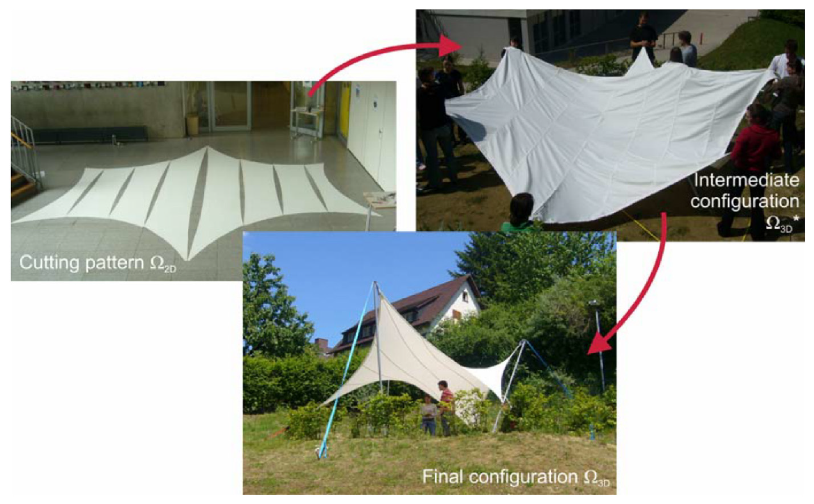
Ultra-thin shells or membranes are found in many engineering fields, from terrestrial applications to space applications, as air-bags, roofs of buildings, fabric structures, exhibition pavilions, parachutes, inflatable reflectors, antennae and solar power collection panels on spacecraft, space-based radars, etc. [1]. Membrane structures are widely used due to their high strength-to-weight ratio, light weight and flexibility. Accordingly, they can be applied flexibly to short-span, long-span and free-form shape buildings, and their behaviors should be particularly investigated. In mechanical models of isotropic membrane structures, due to their thicknesses being very small, it is assumed that the membranes have zero bending stiffness and pure membrane stiffness. Isotropic membrane structures cannot resist loads at the initial or intermediate states as illustrated in Figure 1. They always require a form-finding process to reach the steady state. After this state, the isotropic membranes can resist loads, work in a pure membrane state and quickly experience large deflection, even with a small load. Due to the importance of the form-finding process, many numerical techniques have been developed for form finding, such as: dynamic relaxation [2], force density method [3], a nonlinear solver and updated reference strategy [4], the natural-shape-finding method [5], the direct and indirect approach of the force density method [6,7], the minimal surface method [8], etc.
In attempts to improve the load-carrying capacity and strength of isotropic membrane structures, they are often stiffened by cables for reinforcement of strength. However, cable–membrane composite structures still exhibit some complicated problems, such as: (1) the folding of the membrane by the cable; (2) the sliding of the cable on the membrane surface [10]; (3) cable–membrane structures can only maintain their shapes with in-plane tensile stress [11] and so on. In addition, a form-finding process is still required even when membranes are stiffened by cables [11]. The above problems can lead to some numerical difficulties in modeling cable–membrane composite structures. To overcome the existing difficulties and improve the load-carrying capacity, as well as the strength of membrane structures, functionally graded carbon-nanotube-reinforced composite membrane structures are first proposed and investigated in this paper using a unified adaptive approach (UAA) in the framework of isogeometric analysis (IGA) and the first-order shear deformation theory (FSDT). As an advantage of UAA, both form finding and analysis are performed conveniently and simultaneously based on a modified Riks method. The present structure exploits the advantages of functionally graded carbon-nanotube-reinforced composite (FG-CNTRC) material, such as: a high stiffness, low density, high strength and aspect ratio [12,13,14]. It is interesting that the present approach and formulation can be applied adaptively and naturally to FG-CNTRC plates/shells and membranes from ultra-thin to moderate thick structures without concerning the global stiffnesses of structures. In attempts to develop advanced methods, isogeometric analysis [15] was proposed to solve mechanics problems with exact geometries and high accuracy. IGA has been developed for various types of structures, such as plates [16,17,18,19,20,21,22] and shells [23,24,25,26,27,28,29]. In particular, NURBS-based nonlinear inverse analyses of thin shells were performed not only for pure mechanical problems [30] but also for coupled problems [31]. In addition, IGA has been successfully investigated for isotropic membrane structures, such as: classical shell theory for the analysis of membranes [32], design and analysis [33], vibration analysis [34], shape optimization of vibrating membranes [35], transient analysis [36], form finding with dynamic relaxation [2] and form finding and large deflection analysis [37]. In this paper, the form finding and postbuckling analysis of FG-CNTRC membrane structures are first carried out with the goal of improving the load-carrying capacity and strength of membrane structures. As the developments of IGA, IGAs using PHT-splines [38] and RHT-splines [39] were proposed to drive the adaptive refinement and improve the computational efficiency. In addition, combinations of artificial intelligence [40,41] and computational mechanics have been proposed to analyze structures such as: deep collocation methods [42,43,44], deep energy methods [45] and the deep learned one-iteration method [46].
The paper is organized as follows: a postbuckling analysis of functionally graded carbon-nanotube-reinforced composite membranes is shown in the next section. Section 3 presents the form finding and postbuckling analysis of FG-CNTRC membrane structures using a unified adaptive approach. Results and discussions are adequately provided in Section 4. The paper is closed with several interesting main conclusions in Section 5.
2. Postbuckling Analysis of Functionally Graded Carbon-Nanotube-Reinforced Composite Ultra-Thin Shells or Membranes
2.1. Functionally Graded Carbon-Nanotube-Reinforced Composite Membranes
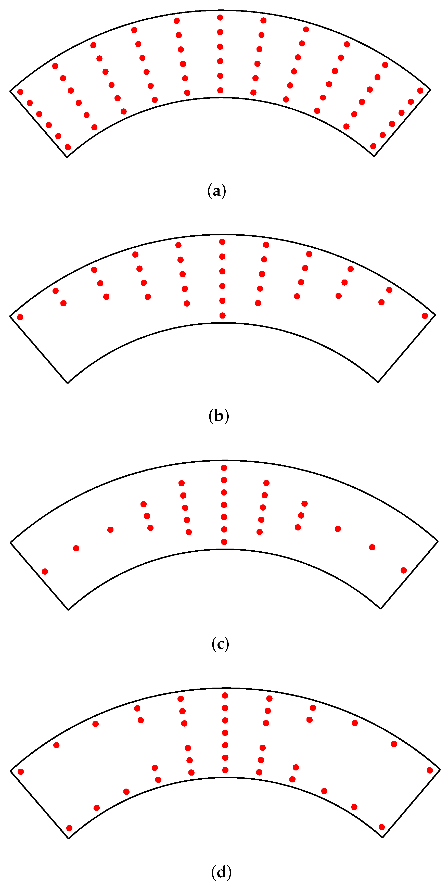
All of the FG-CNTRC membrane structures in this study are investigated with four types of CNT distributions as described in Figure 2. Four corresponding CNT volume fractions are determined as follows:
and
It is assumed that the CNTs mass fraction is equal for the four types of FG-CNTRC membranes. In addition, and , respectively, are the densities of CNTs and the matrix, and h is defined as the thickness of membranes. In this study, we employ the rule of mixture [47,48] to estimate the effective properties of CNT-reinforced materials as
where is the shear modulus and , are Young’s moduli of CNTs. is the shear modulus and is Young’s modulus of the isotropic matrix material. In addition, and , respectively, denote the volume fractions of the matrix material and the CNTs. The sum of these volume fractions is one. The efficient parameters are considered to account for the scale-dependent material properties of CNTs. Poisson’s ratio and the density can be determined as follows:
where and , respectively, are Poisson’s ratios of the CNTs and the matrix material. Note that is constant along the membrane thickness.
2.2. Postbuckling Analysis of FG-CNTRC Membrane Structures Using FSDT
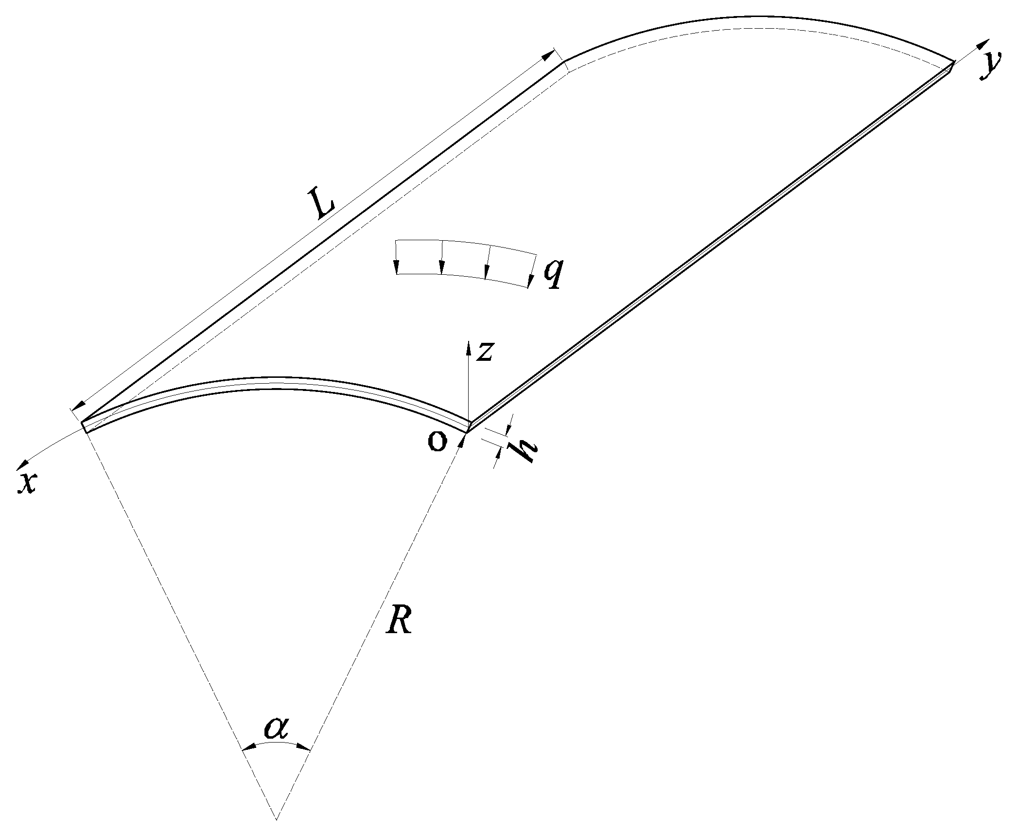
Different from the classical membrane theory, the present theory (FSDT) simultaneously takes into account the membrane, shear and bending strains/stiffnesses of structures. Hence, the present formulation can be used adaptively and naturally for various types of FG-CNTRC structures—plates, shells and membranes—without concerning the global stiffnesses of structures. Firstly, we investigate a FG-CNTRC cylindrical membrane structure with the initial geometry given in Figure 3. The displacements of an arbitrary point in the membrane based on FSDT are defined as [49,50,51].
and
where , are the tangential displacement components and is the radial displacement component or the deflection of the considering point. and , respectively, are the rotations in the y and the x axes. The strains in the orthogonal curvilinear coordinate system (oxyz) with the von Karman assumption are defined as [51]
and
The nonlinear strain component is re-expressed as
The virtual work equation of the FG-CNTRC membrane structure is written as follows:
where the load vector . For the postbuckling analysis of the FG-CNTRC membrane structure subjected to a radial pressure , the virtual work equation is conveniently re-written as
where and , respectively, denote the load factor and the stress resultant vector. The vector is defined as
This vector has three components:
In plane
bending
shear
Hooke’s law is used to describe the relationship between the generalized strain vector and the stress resultant vector as
with
In this study, we employ the shear correction factor [49] and
3. Form Finding and Postbuckling Analysis of FG-CNTRC Membrane Structures Using a Unified Adaptive Approach
3.1. A Brief Introduction to the Unified Adaptive Approach (UAA) for Form Finding and Analysis of Membrane Structures
For the analysis of an isotropic membrane, a form-finding process is first carried out to reach the steady state or to achieve the new geometry of the membrane. Next, the analysis step is conducted based on this new geometry. In this step, the isotropic membrane works in a pure membrane state and can experience large deflection quickly, even with a very small load. For the analysis of membrane structures using the conventional numerical approach, form finding and analysis are separately carried out, including a form-finding process and numerical techniques for the geometrically nonlinear analysis of membranes. In this study, the form finding and analysis of FG-CNTRC membrane structures are conducted at the same time using the unified adaptive approach (UAA), which exploits the advantage of the modified Riks nonlinear solver [37]. Note that, when employing the nonlinear solver for form finding, the shape-generating load is often a surface load, such as: snow, self-weight [4], etc. In this study, the surface load is employed for the two processes: form finding and analysis. For isotropic membrane structures, a new type of equilibrium path at the central point was proposed based on UAA. This path includes two parts: one is achieved via form finding and the rest is from the analysis [37].
3.2. A Brief Introduction to Non-Uniform Rational B-Splines Basis Functions
In this subsection, we present a summarization of non-uniform rational B-spline (NURBS) basis functions. The details, as well as source codes, of isogeometric analysis using NURBS basis functions can be found in [52]. We first investigate a knot vector , with . This vector is open if the last and first knots are repeated times. Note that a B-spline basis function has the continuity at each knot while it has the continuity inside a knot span. The B-spline basis functions in the one-dimensional parametric space are determined as follows [53]:
We next investigate two knot vectors in the two-dimensional parametric space and . The B-spline basis functions in this space can be determined via a tensor product as
The NURBS basis functions can be employed to exactly describe geometries and are determined by assigning the weight w for each control point as follows [15]:
Note that the NURBS and the B-spline basis functions are completely the same if all of the weights of the control points are identical.
3.3. Form Finding and Postbuckling Analysis of FG-CNTRC Membrane Structures Using UAA and NURBS
Applying the unified adaptive approach (UAA) [37], both form finding and postbuckling analysis are carried out at the same time via a modified Riks nonlinear solver as mentioned earlier. In the present formulation, NURBS basis functions are employed to interpolate geometries and displacements of membranes as follows:
denotes the NURBS basis function and stands for the control point coordinate. The vector involves degrees of freedom of the typical control point A. In addition, the vector contains the physical point coordinates and denotes the interpolated displacement vector.
Combining Equations (11) and (25), the strain vectors can be interpolated via the control point displacements as
and
Substituting Equation (25) into Equation (12), the interpolated nonlinear strain vector is achieved as follows:
We substitute the interpolated strains from Equations (26) and (28) into Equation (19) and achieve the variation of the generalized strain vector as
Next, the terms in Equations (25) and (29) are substituted into Equation (14). We then eliminate the virtual displacement component. The nonlinear equation can be written conveniently as follows:
In this study, the nonlinear equation in (30) is iteratively solved by employing the modified Riks method [54]. When a change in the load from to is created, a new equilibrium configuration close to the old one is reached and expressed as
Only taking into account the first term after applying the Taylor series expansion to Equation (31), we achieve a system of the linear incremental equilibrium equations as
where stands for the tangent stiffness matrix determined at as
We next carry out an iterative process for all load increments [54]. Conveniently, Equations (32) and (33) can be re-expressed in a generalized form with the mth load increment and the ith iteration as
with
and the load vector
where denotes the referenced load vector, while the internal load vector is determined as
We substitute all of the terms in Equations (19), (26), (28) and (29) into Equation (37) and obtain the following equation:
with
The iterative computation is carried out for all load increments. To check the convergence of solutions, the criterion based on the residual load vector is applied as
4. Results and Discussion
4.1. Verification Study
This section aims to confirm the accuracy of the present formulation and approach for the form finding and postbuckling analysis of FG-CNTRC membrane structures. It should be noted that a high accuracy of the present approach for the form finding and analysis of isotropic membrane structures was confirmed in [37]. In addition, this is the first study on the analysis of FG-CNTRC membrane structures, and there is no reference solution in the literature to compare to. Accordingly, the proposed formulation and approach are verified via some benchmarks of isotropic FG-CNTRC cylindrical shell structures and a composite circular cylinder shell. In this work, the central deflection is positive, corresponding to the central point, which is deflected downward. Inversely, the central deflection is negative, corresponding to the central point, which is deflected upward. The load is downward pressure as illustrated in Figure 3. In this study, the surface load with a small load step N/m2 is employed as the shape-generating load. This load is used for the two processes: form finding and analysis. For the convenience and efficiency, all of the problems in this study are analyzed employing the mesh of 14 × 14 cubic elements and 4 × 4 Gauss points per each element. The armchair SWCNTs [55] and Poly methyl methacrylate (PMMA) [56] are, respectively, employed as the reinforcements and the matrix material for FG-CNTRC membranes. In addition, all of the membranes are circumferentially reinforced with CNTs. Material properties at room temperature are employed as
- The CNTs reinforcement materialTPa, TPa, TPa, , ;
- The PMMA matrix materialGPa, , .
For the CNTs reinforcement material, the efficiency parameters corresponding to the volume fractions are given as [55]
- : and ;
- : and ;
- : and .
We can assume that and . For an FG-CNTRC membrane with the initial geometry as described in Figure 3, the clamped boundary is directly imposed as
In this study, two non-dimensional parameters are defined and investigated as follows:
- Normalized central deflection: ;
- Curvature: .
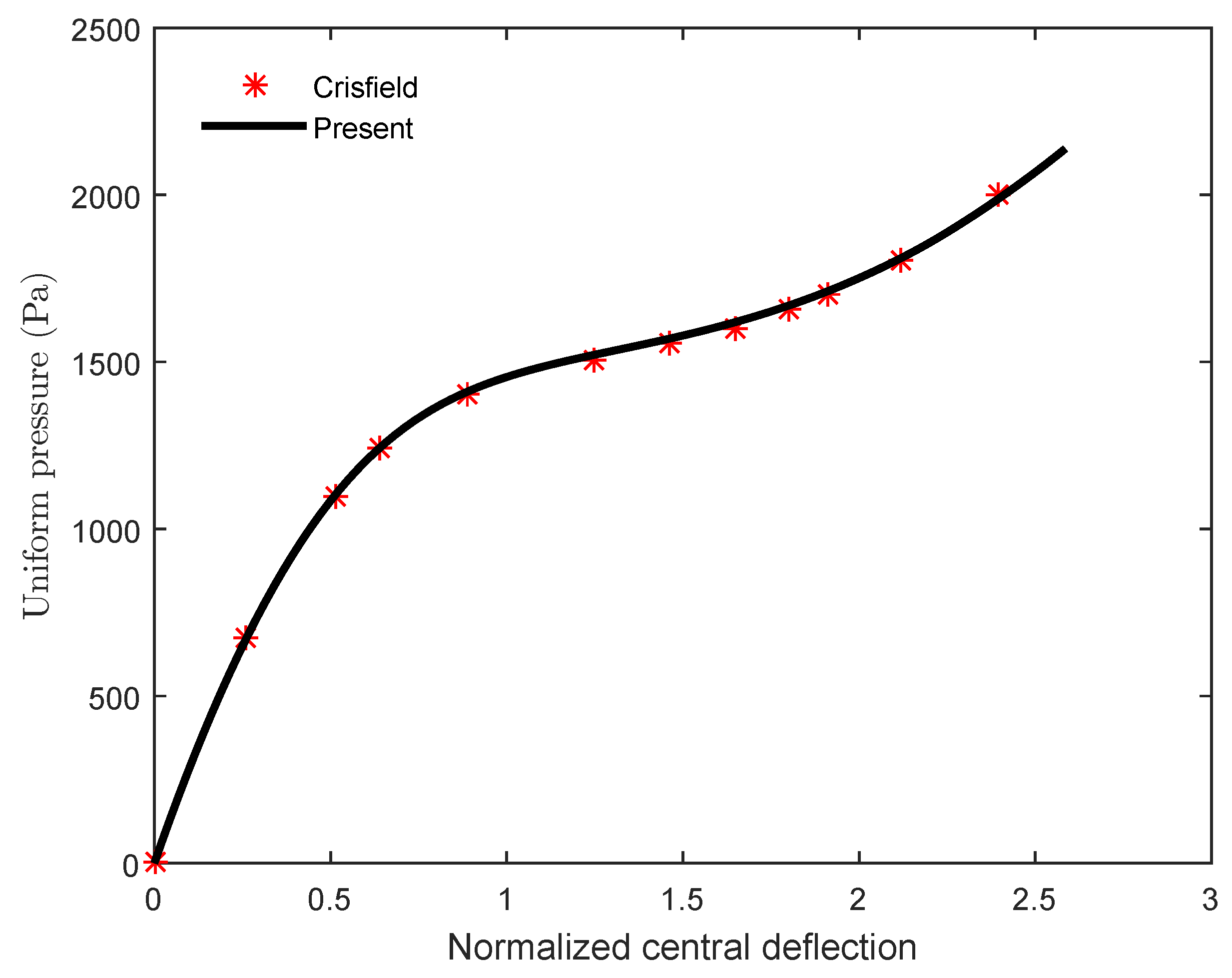
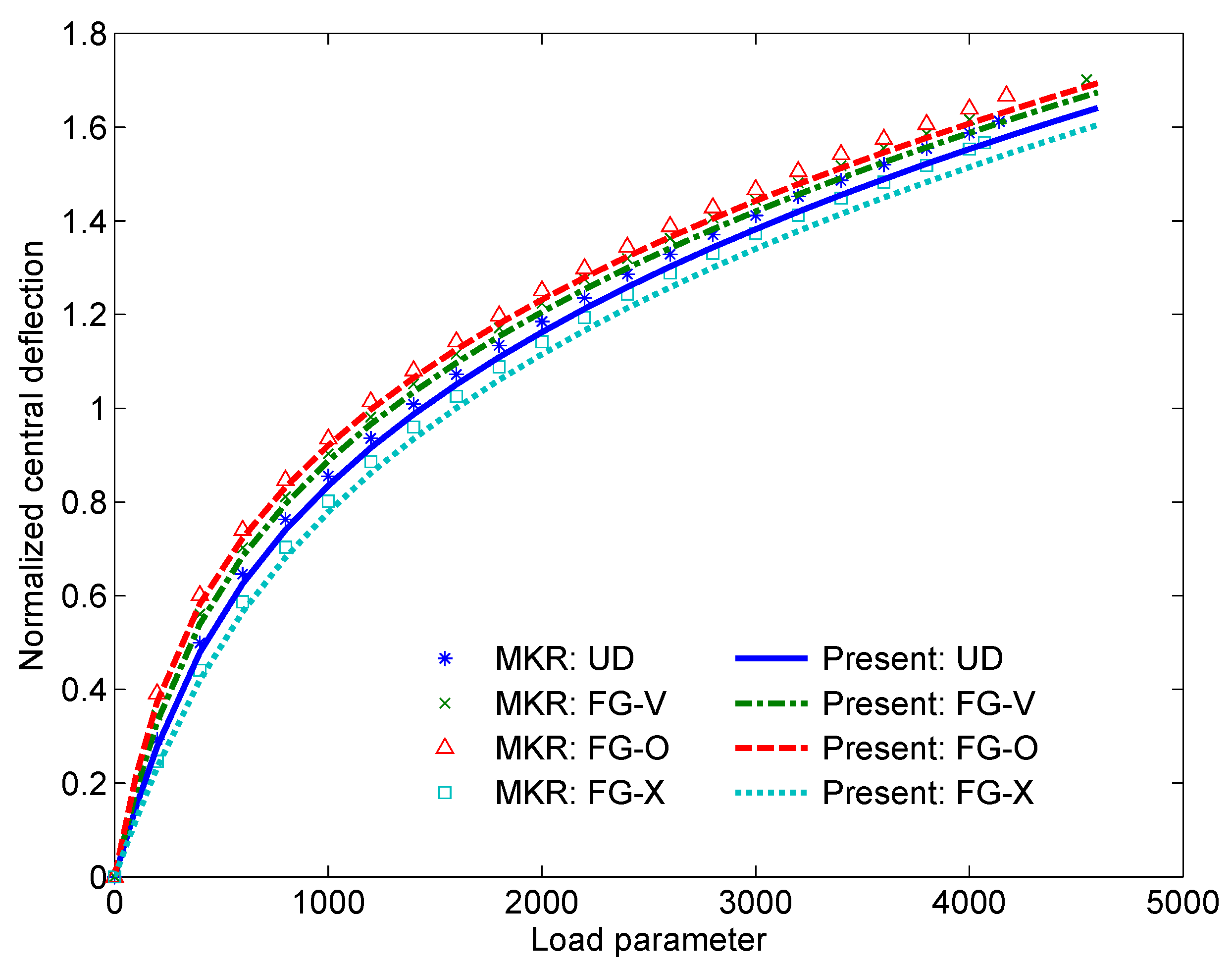
In this section, geometrically nonlinear analyses of isotropic and FG-CNTRC cylindrical shell structures are carried out to verify the present formulation and approach. Firstly, we investigate a fully clamped isotropic cylindrical panel subjected to a pressure. The geometry of the panel is determined as: the thickness mm, mm and the radius mm. The characteristics of the material are Poisson’s ratio and Young’s modulus . The obtained result is presented in Figure 4 in a comparison with the result of Crisfield [57] using the finite element method. A very good agreement is found. Next, a fully clamped FG-CNTRC cylindrical panel subjected to a pressure, as shown in Figure 3, is investigated. The geometry of the panel is described as follows: rad, and . The obtained results are shown in Figure 5 in a comparison with the results of the mesh-free kp-Ritz method (MKR) [58]. A very good agreement is obtained for all types of CNTs distributions. It can be seen that the present approach and formulation have a high accuracy for nonlinear analyses of isotropic and FG-CNTRC cylindrical shell structures. Finally, we can conclude that the present approach and formulation have a high accuracy for the form finding and postbuckling analysis of FG-CNTRC membrane structures.
4.2. Parametric Study
4.2.1. FG-CNTRC Cylindrical Membranes
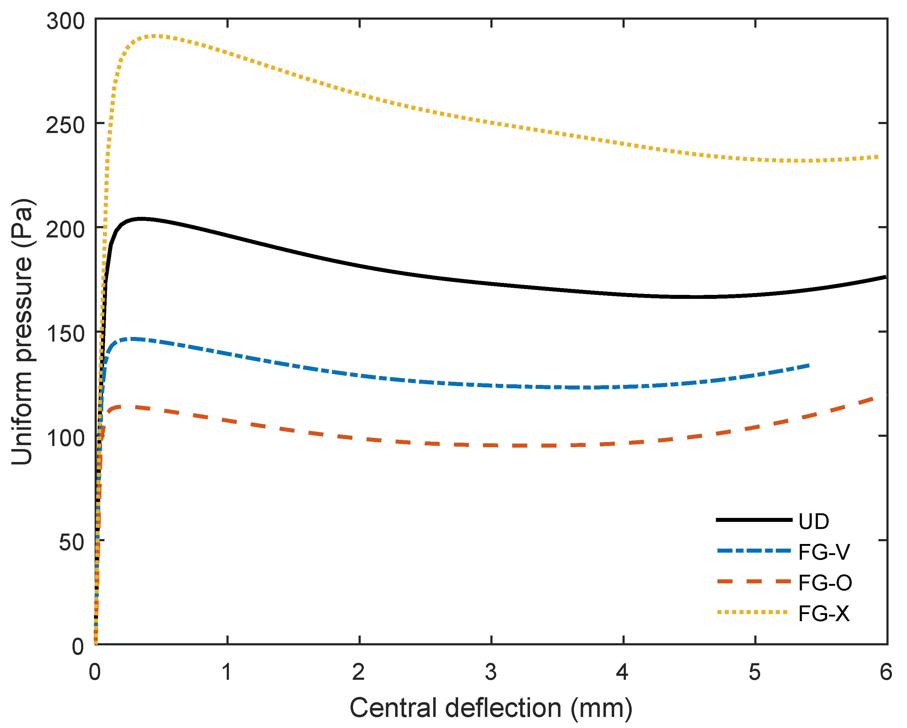
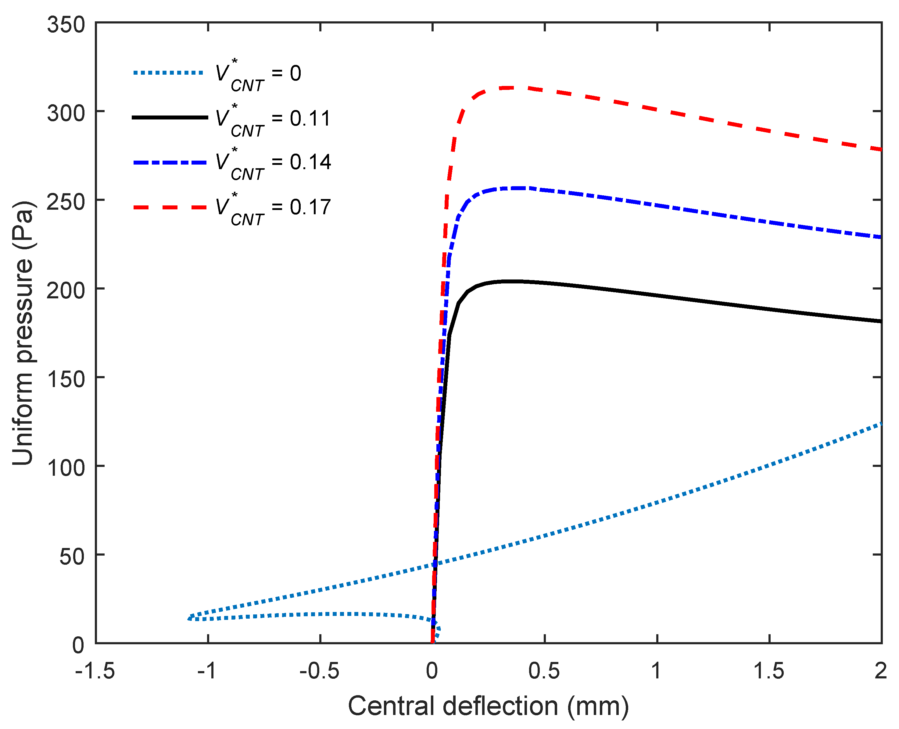
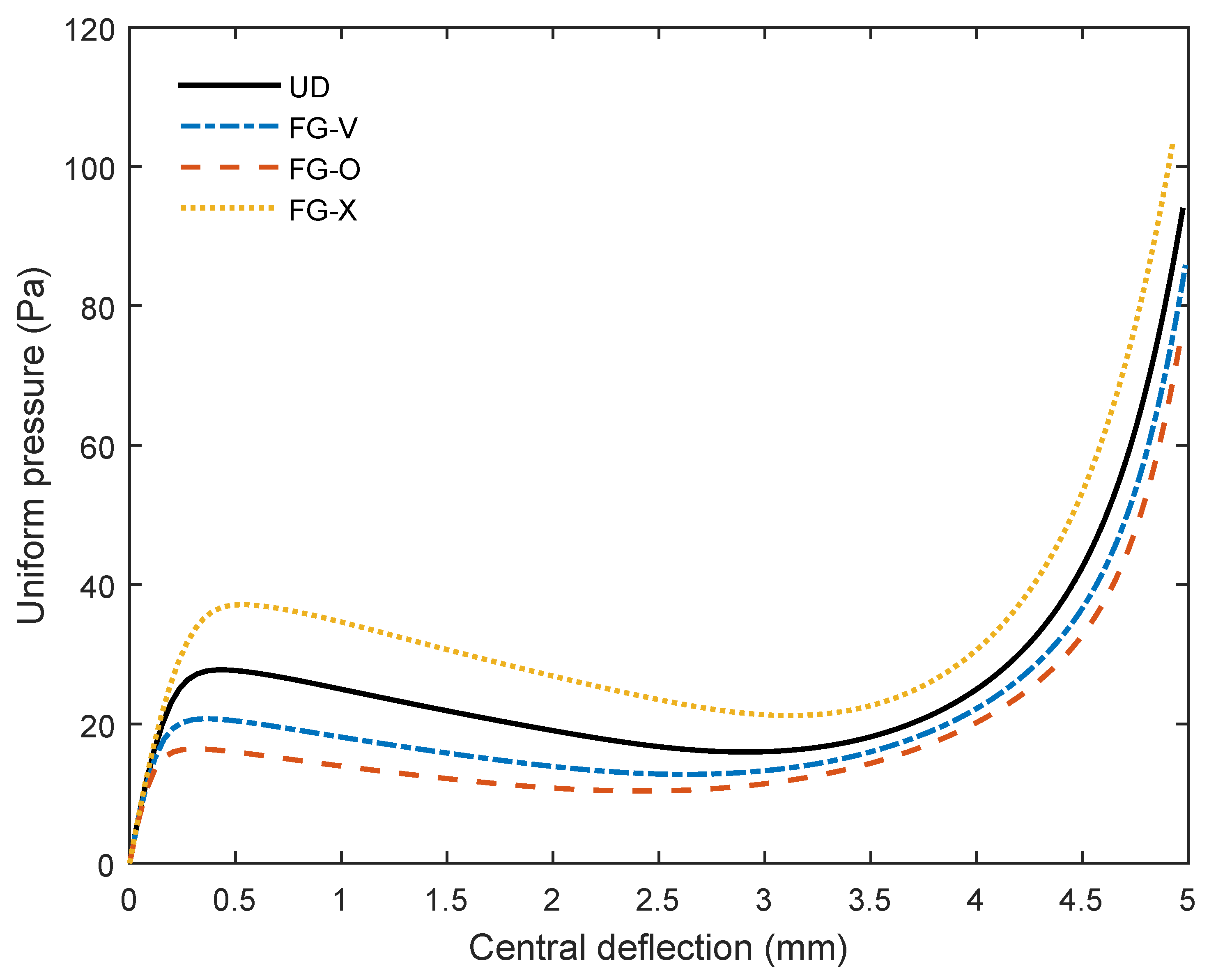
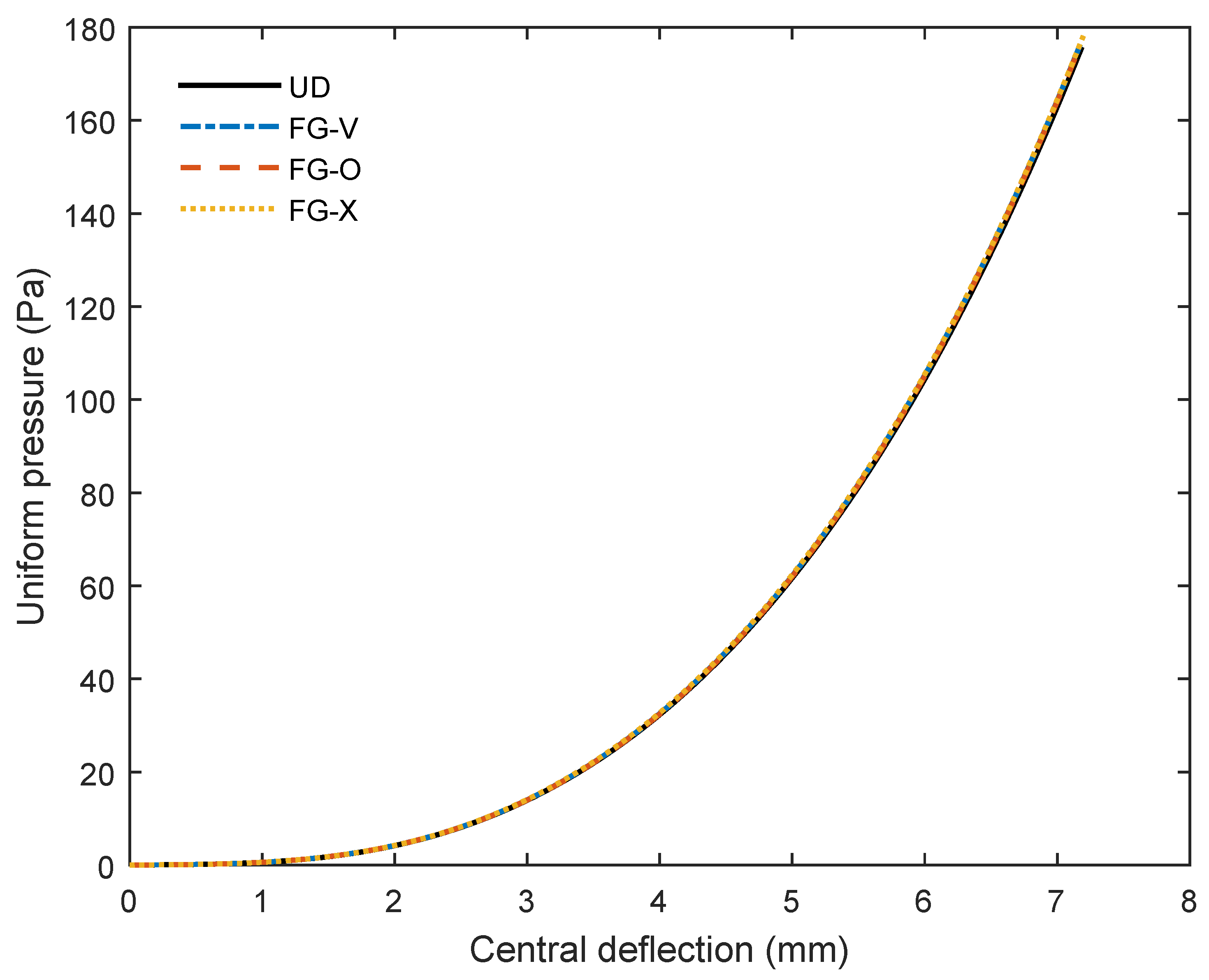
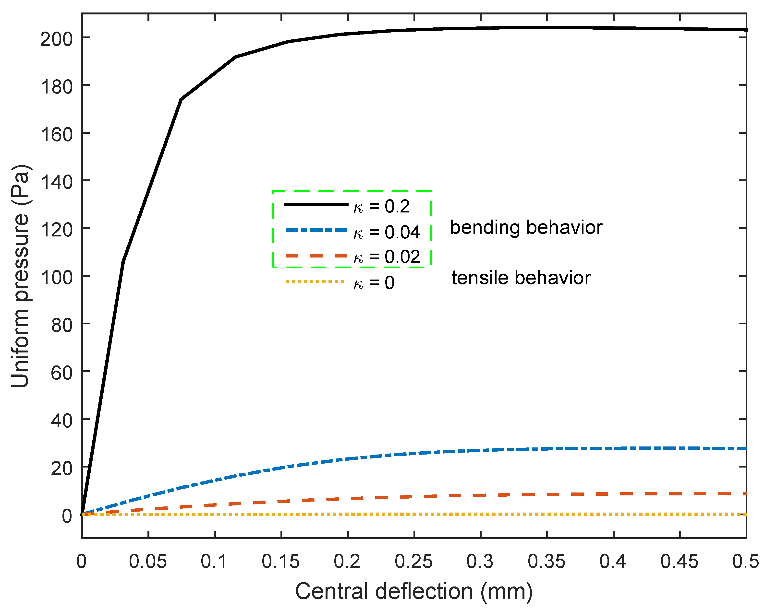
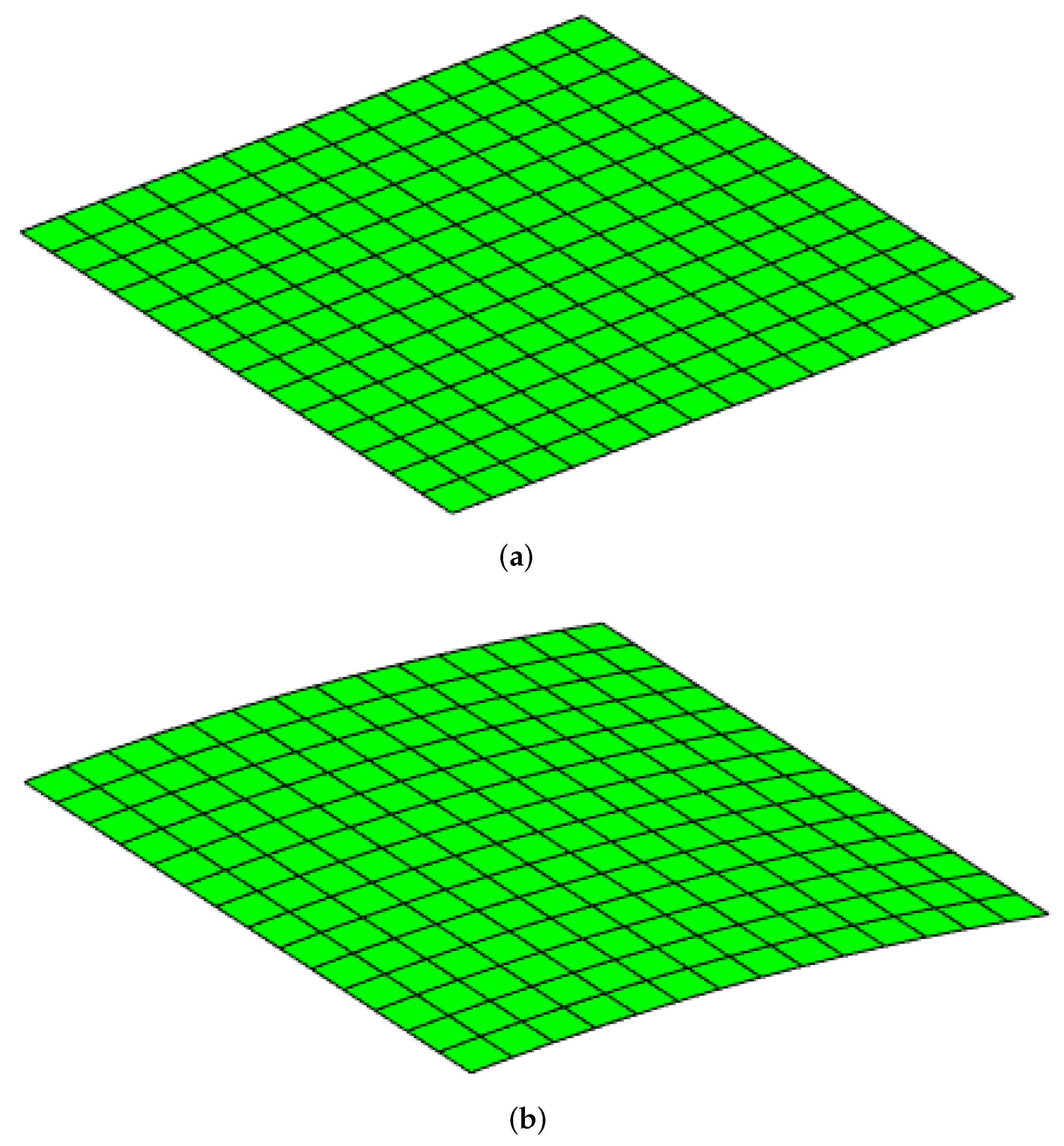
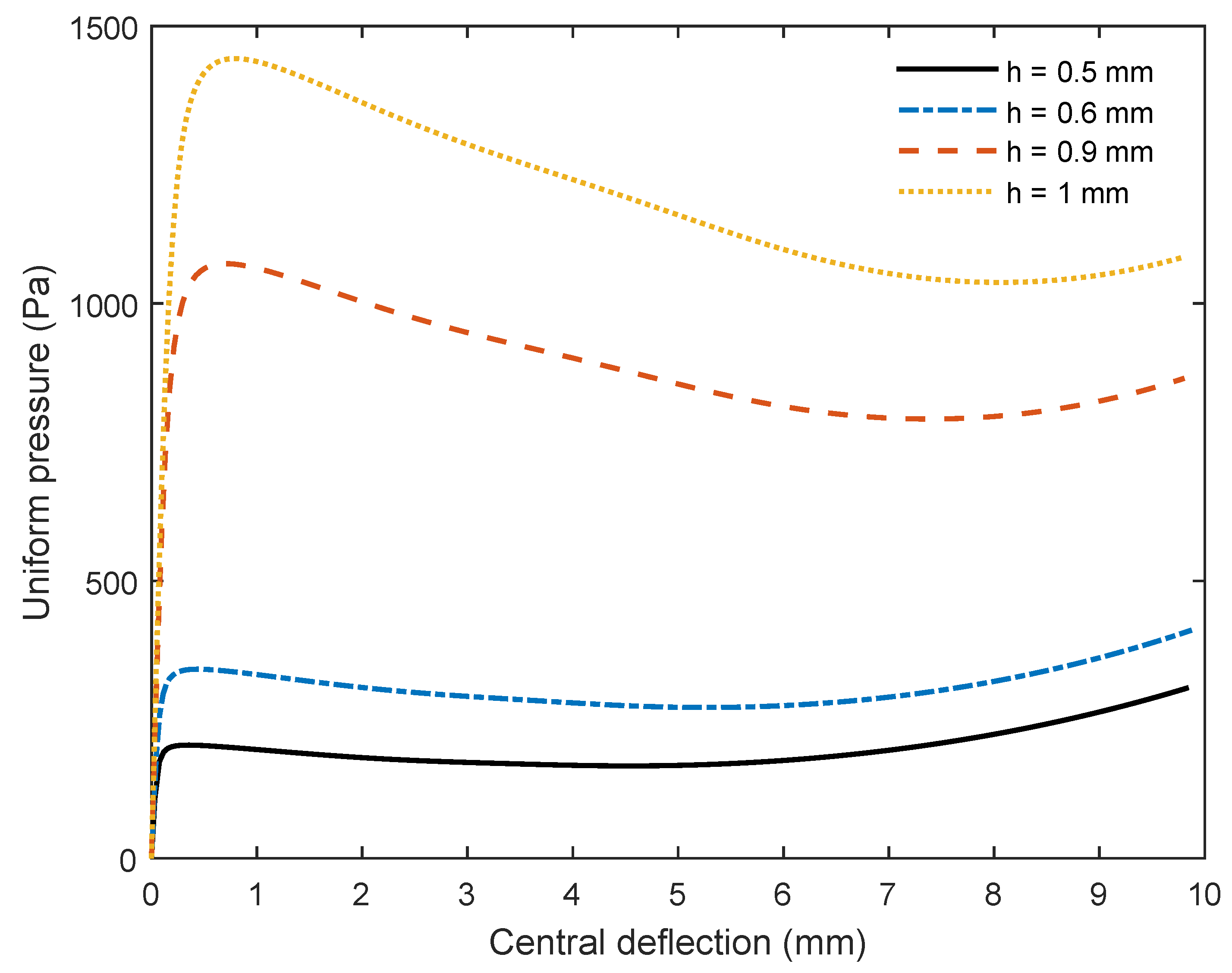
In this section, we consider a fully clamped cylindrical membrane structure under a pressure. The geometric characteristics of the cylindrical membrane (C-M) are the thickness mm, mm and the radius mm. First, we investigate the behavior of the cylindrical membrane with the isotropic material as Poisson’s ratio and Young’s modulus . The obtained result is presented in Figure 6. It is interesting that, although the loading is downward, the central point is deflected upward at the beginning. This phenomenon occurs due to the form-finding process as explained in [37], published by the authors of this paper. It is observed that the structure works in a pure membrane state and quickly experiences large deflection behavior, even with a small pressure, as seen in Figure 6. It should be noted that the results in Figure 4 and Figure 6 are obtained from two models with the same material, geometric data, loading and boundary condition. The only difference is the thickness ( mm and mm). It is clear that behaviors of the isotropic membrane and thin-shell structures are completely different. Next, we investigate the behavior of the above cylindrical membrane structure (C-M) with the FG-CNTRC material. The obtained results are depicted in Figure 7. It is interesting that, when using the FG-CNTRC material, the membrane structure works as a bending structure. It is clear that behaviors of the isotropic and FG-CNTRC membrane structures are completely different as seen in Figure 6 and Figure 7. The FG-CNTRC membrane structure can resist the load at the beginning without finding a new geometry, which usually occurs in any isotropic membrane structures (the so-called form-finding procedure). Using the same geometric data, loading and boundary condition, the FG-CNTRC membrane structure has a significantly higher nonlinear strength compared with the isotropic membrane structure as seen in Figure 6 and Figure 7. It can be concluded that using the FG-CNTRC material for membrane structures is very efficient. It is observed that FG-X is the best distribution and the one that gives the greatest postbuckling strength. Figure 8 shows the effect of CNTs volume fraction on the nonlinear response of the FG-CNTRC cylindrical membrane structure. The larger the amount of CNTs in the membrane, the higher the postbuckling strength. Without CNTs reinforcement (), the membrane cannot resist the load at the initial state and requires a form-finding process to reach the steady state. Conversely, with CNTs reinforcement, the membranes can resist the load at the beginning. It is concluded that CNTs reinforcement can create a load-carrying capacity for cylindrical membrane structures, even at the initial state. Figure 7, Figure 9 and Figure 10 show the effect of CNTs distribution on the nonlinear response of the FG-CNTRC membrane with various curvatures . It is observed that the smaller the curvature of the membrane structure, the lower the postbuckling strength. It is clear that using the FG-CNTRC material for the cylindrical membrane structure is very effective, whereas, for the square membrane structure, it is not effective. As seen in Figure 7 and Figure 10, although various types of CNT distributions are investigated, the nonlinear strength of the square membrane structure () does not change, whereas that of the cylindrical membrane structure is significantly improved. As mentioned earlier, FG-X is the best distribution and the one that gives the greatest postbuckling strength. Accordingly, using the FG-CNTRC material for cylindrical membrane structures is very effective and recommended, whereas using it for square membrane structures is not recommended. It is interesting to note that, when the curvature of the membrane is very small— (an almost flat membrane)—the membrane still works as a bending structure. However, when the curvature , the square membrane works as a pure tensile structure. This phenomenon occurs due to the fact that CNTs reinforcement in the circumferential direction can significantly improve the nonlinear bending strength of the membrane structure, even when the curvature is small. In addition, Figure 11 shows a strong effect of the curvature on the nonlinear response and behavior of the FG-CNTRC membrane, although the change in curvature is very small, as described in Figure 12. As seen in Figure 11, the membrane works as a bending structure even when the curvature of the membrane is very small but not equal to zero. However, when the curvature , the square membrane suddenly works as a pure tensile structure. It is noted that the classical membrane theory cannot model FG-CNTRC membranes correctly due to the present of bending stiffness created by CNTs reinforcement. Different from the classical membrane theory, the present theory (first-order shear deformation theory) simultaneously takes into account the membrane, shear and bending strains/stiffnesses of structures. Accordingly, the present formulation can be applied adaptively and naturally to various types of behaviors and structures, such as: FG-CNTRC plates/shells and membranes. The high efficiency of the present formulation is confirmed. The effect of the thickness on the nonlinear response of the FG-CNTRC cylindrical membrane is very significant as seen in Figure 13. It can be concluded that, for an FG-CNTRC cylindrical membrane structure, an ultra-small change in thickness or curvature can lead to a significant change in its nonlinear response, strength and behavior.
4.2.2. FG-CNTRC Circular Cylinder Membranes
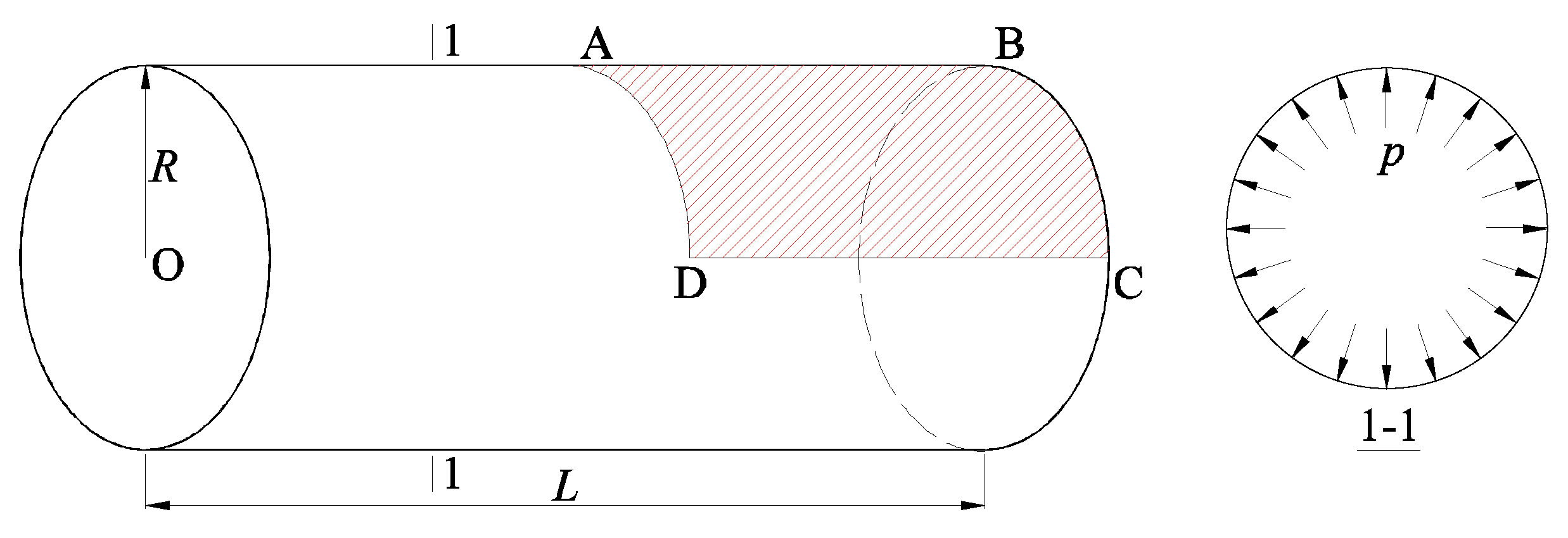
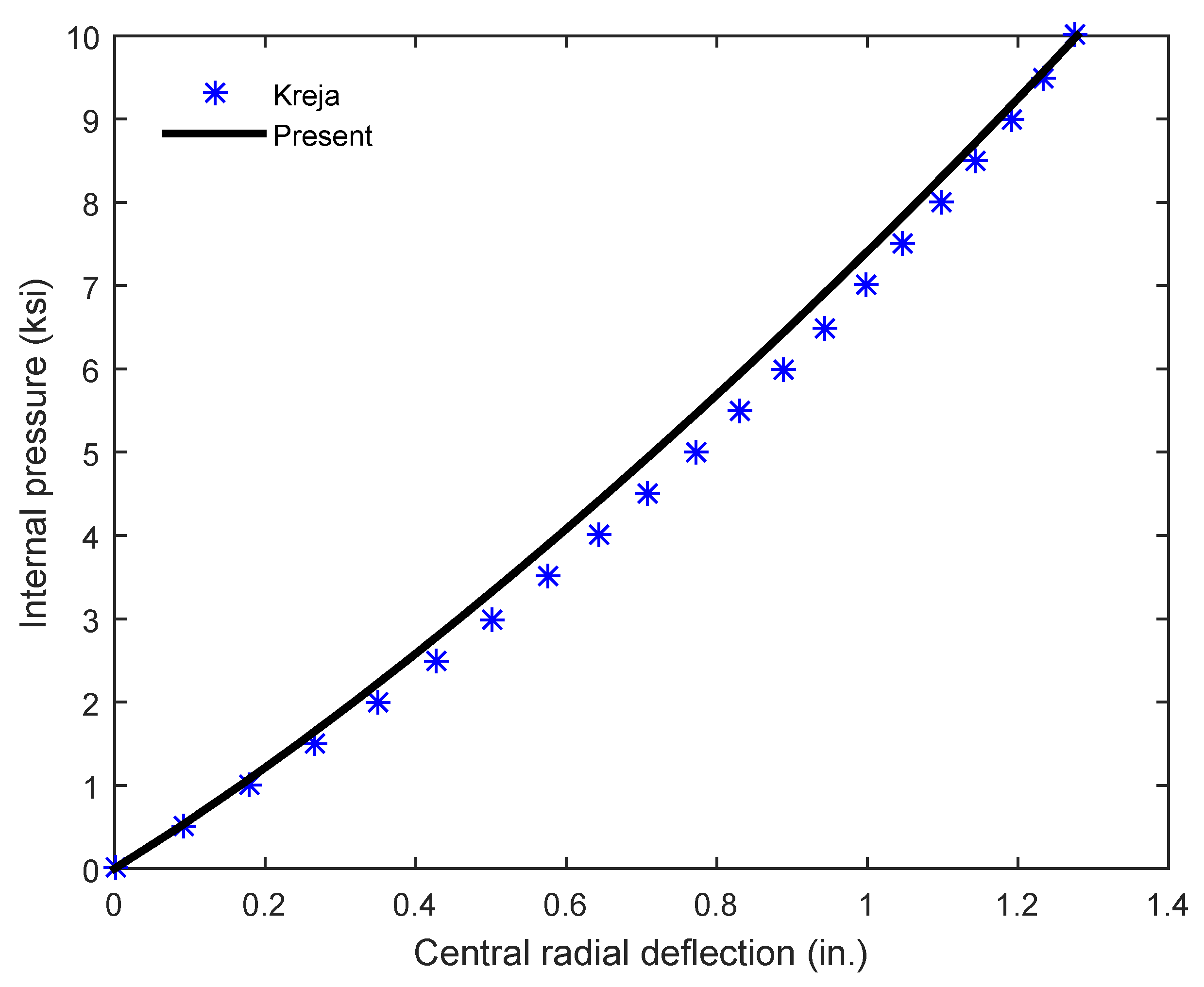
We next analyze a glass–epoxy circular cylinder shell with an internal pressure as illustrated in Figure 14. The cylinder is fully clamped at two ends. The properties of the geometry are given as follows: the thickness in., the radius in. and the length in. The material data are provided as follows: ksi, ksi, , ksi and ksi. We exploit the symmetry of the cylinder shell: one eighth (ABCD) of the cylinder is analyzed without a loss of accuracy of the solution. The achieved result is presented in Figure 15 in a comparison with the result of Kreja [59] employing FEM. The present solution has a good agreement with the referenced one. It can be concluded that the present formulation and approach have a high reliability in predicting the geometrically nonlinear behavior of orthotropic cylinder shells.
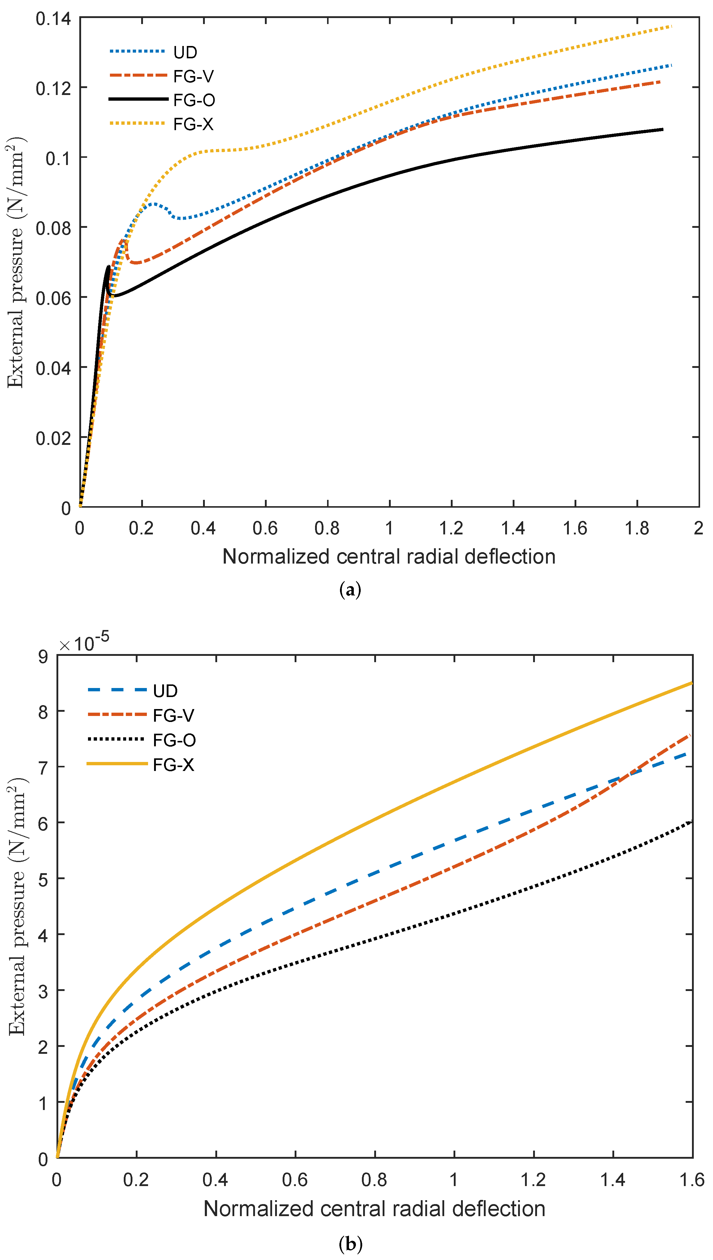
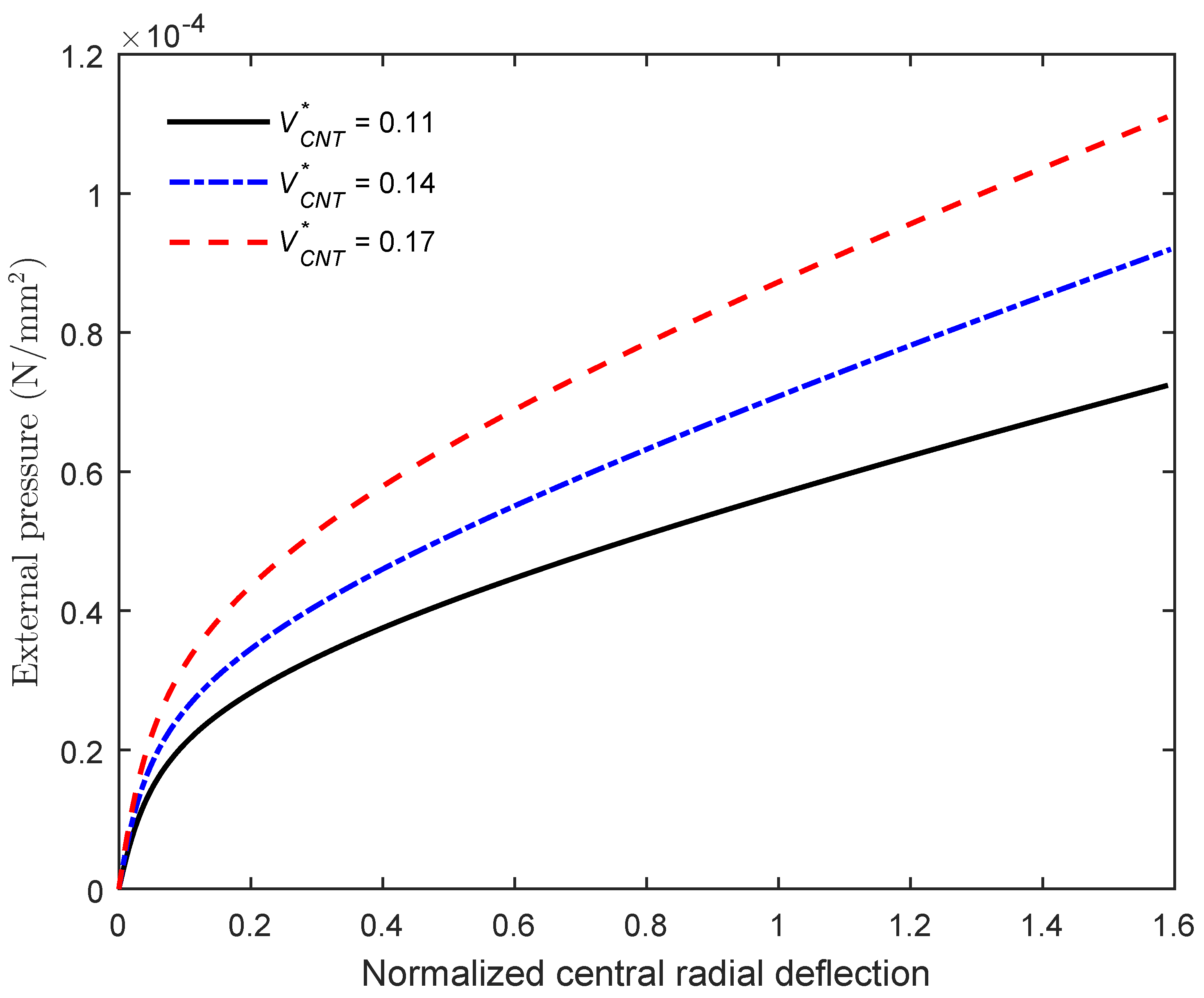
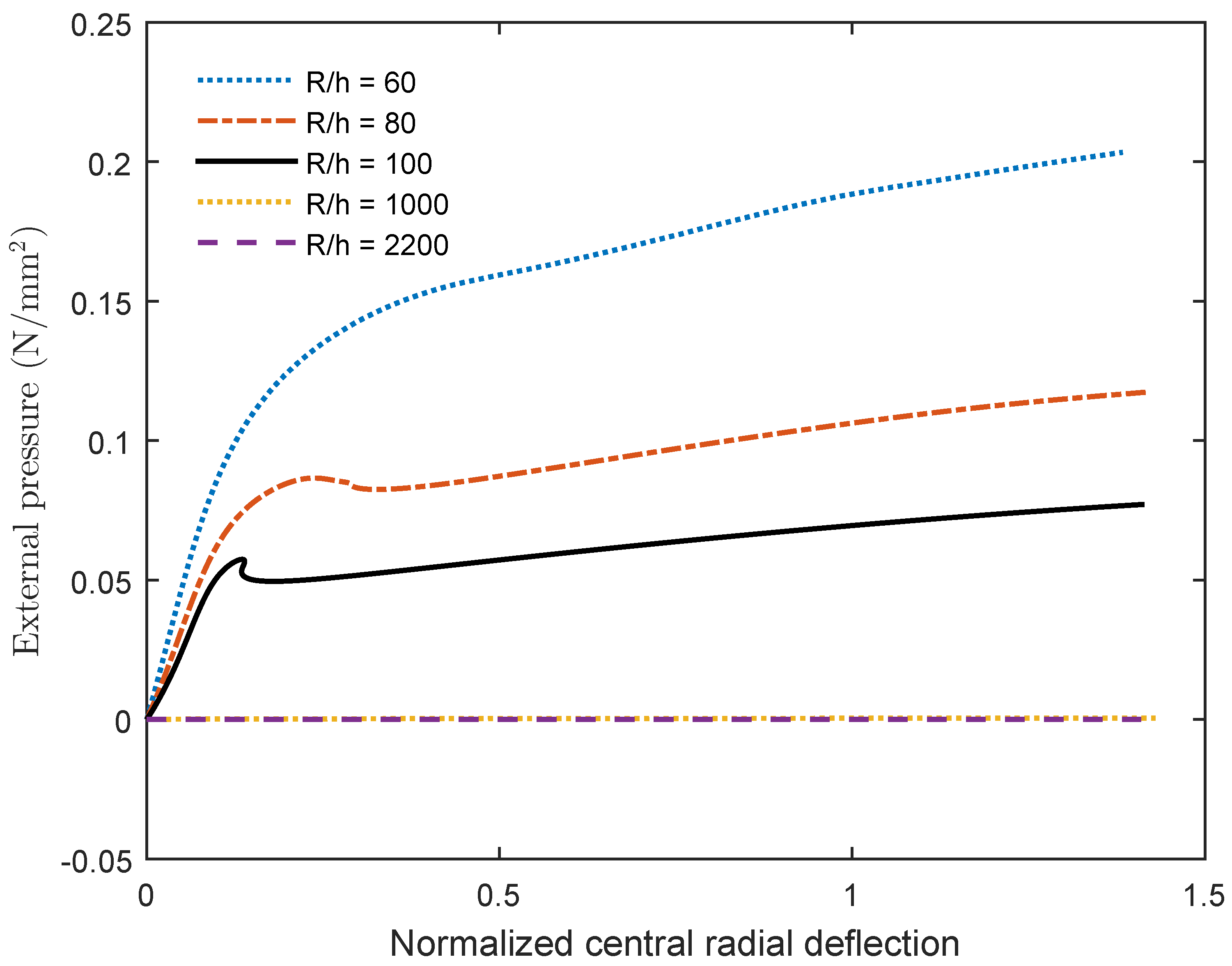
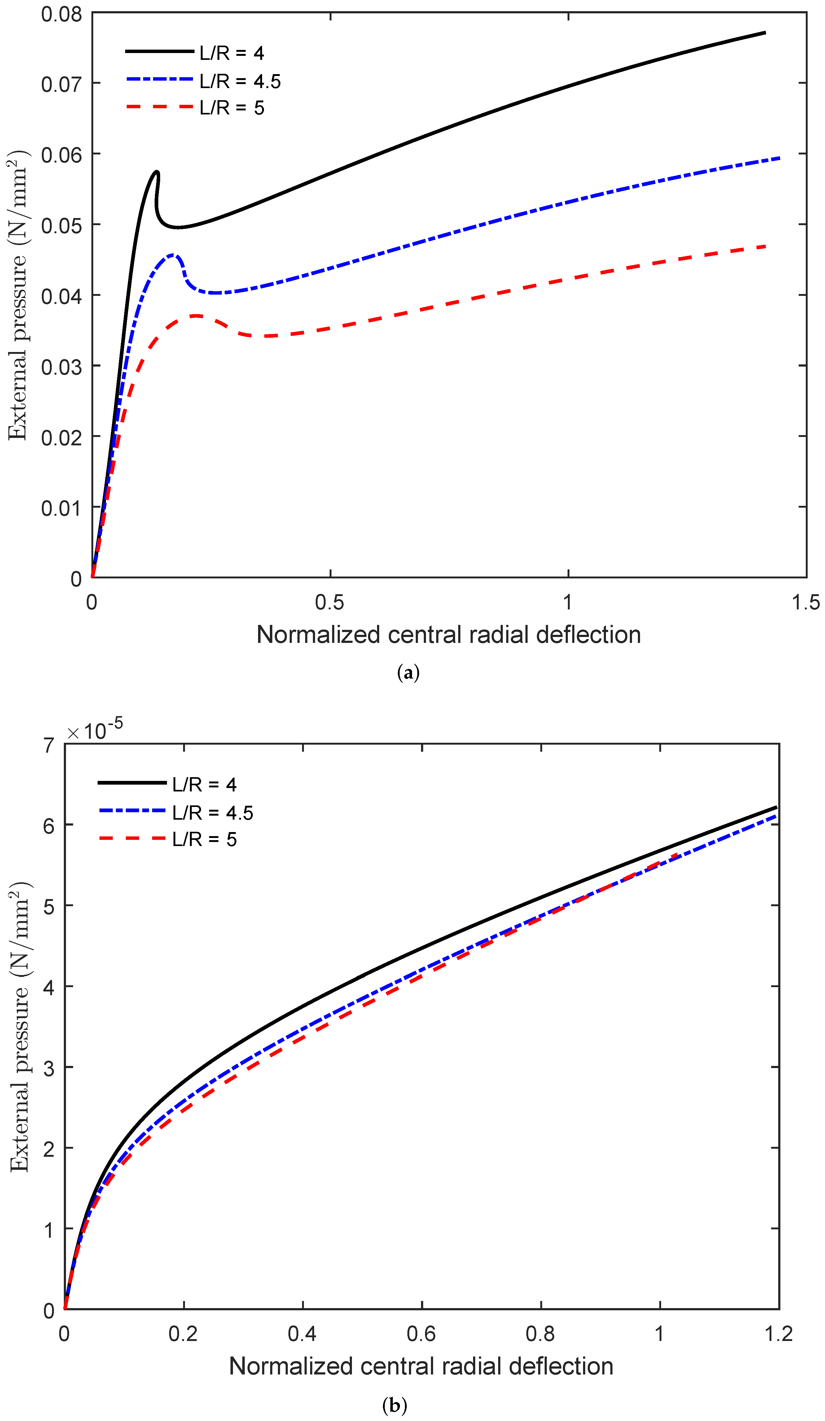
Next, an adequate investigation into nonlinear behaviors of FG-CNTRC circular cylinder shells and membranes is first performed in this study. Fully clamped FG-CNTRC cylinder shells and membranes with a fixed thickness in. under external pressure are considered. Figure 16 shows the significant effects of CNTs distribution on nonlinear responses of the FG-CNTRC cylinder shell and membrane. For the cylinder shells, instabilities including “snap-through” or “snap-back” occur depending on the CNTs distribution. It is interesting to note that the cylinder membranes are stable during loading and quickly experience large deflection behavior, even with a very small amplitude of pressure. For both FG-CNTRC cylinder shells and membranes, FG-O is the worst distribution and the one that gives the lowest nonlinear strength, and FG-X is the best distribution and the one that gives the greatest nonlinear strength. Figure 17 shows the effect of the CNTs volume fraction on the nonlinear response of the FG-CNTRC cylinder membrane. It is clear that, the greater the amount of CNTs in the membrane, the greater the nonlinear strength. The effects of the radius-to-thickness ratio on nonlinear responses of the FG-CNTRC cylinder shell and membrane are described in Figure 18. For the cylinder shells (∼100), instabilities can occur, whereas the cylinder membranes (∼2200) are stable and quickly experience large deflection behavior. The effect of the radius-to-thickness ratio on the nonlinear response of the cylinder shell is very significant, whereas there is no effect of this ratio on the response of the cylinder membrane. Finally, Figure 19 shows the effects of the length-to-radius ratio on nonlinear responses of the FG-CNTRC cylinder shell and membrane. The effect of the length-to-radius ratio on the instability and nonlinear response of the FG-CNTRC cylinder shell is significant. However, this ratio almost does not affect the instability and nonlinear response of the FG-CNTRC cylinder membrane.
5. Conclusions
The load-carrying capacity and nonlinear behavior of ultra-thin shells or membranes with and without CNTs reinforcement have been investigated for the first time using a unified adaptive approach (UAA). As an advantage of UAA, both form finding and a postbuckling analysis are performed conveniently and simultaneously based on a modified Riks method. Different from the classical membrane theory, the present theory (FSDT) simultaneously takes into account the membrane, shear and bending strains/stiffnesses of structures. Accordingly, the present formulation can be applied adaptively and naturally to various types of FG-CNTRC structures—plates, shells and membranes—without any restriction or modification. The high accuracy of the present approach and formulation was verified via the benchmark problems. In particular, equilibrium paths of FG-CNTRC membrane structures have been provided for the first time in this paper, which could be useful for future references. From the parametric study, interesting major conclusions can be drawn:
- Isotropic membrane structures always require a form-finding process to reach the steady state and then work in a pure membrane state under the load. However, FG-CNTRC cylindrical membrane structures work as bending structures and can resist loading at the beginning without needing the form-finding process. Accordingly, using the FG-CNTRC material can create a load-carrying capacity for cylindrical membrane structures, even at the initial state.
- For a FG-CNTRC cylindrical membrane structure, an ultra-small change in thickness can lead to a significant change in its nonlinear response and strength.
- Using the FG-CNTRC material for cylindrical membrane structures is very effective and recommended, whereas, for flat membrane structures, it is not recommended.
- A FG-CNTRC cylindrical membrane works as a bending structure, even when the curvature of the membrane is very small but not equal to zero. However, when the curvature , the square membrane suddenly works as a pure tensile structure.
- Under external pressure, for FG-CNTRC circular cylinder shells, types of instabilities with various critical buckling loads can occur, whereas FG-CNTRC circular cylinder membranes are stable and quickly experience large deflection behavior, even with a very small amplitude of pressure.
- Radius-to-thickness and length-to-radius ratios significantly affect the instability and nonlinear response of FG-CNTRC circular cylinder shells, but almost do not affect those of FG-CNTRC circular cylinder membranes. Meanwhile, the CNTs distribution and volume fraction significantly affect nonlinear responses of both FG-CNTRC circular cylinder shells/membranes.
- FG-X is the best distribution and the one that gives the greatest nonlinear strength of a FG-CNTRC membrane structure. The greater the amount of CNTs in the membrane, the greater the nonlinear strength.
The present work has some novelties, obtains new results using IGA and significantly improves the load-carrying capabilities of ultra-thin structures via using CNTs reinforcement. However, this work has some limitations that we need to overcome in future works, which are as follows: (1) the present formulation is applicable to plates or shells with one curvature. It should be developed and improved to model free-form shells; (2) in this work, the rule of mixture is used to calculate the effective properties of CNT-reinforced materials. The rule of mixture does not consider the interface behavior between the reinforcement and the matrix material. In future, we should use some material models that can consider this interface behavior.
Author Contributions
Data curation, T.N.N.; Investigation, T.N.N.; Supervision, J.L.; Visualization, L.M.D.; Writing—review & editing, T.N.N. and P.V.N. All authors have read and agreed to the published version of the manuscript.
Funding
This research was funded by National Research Foundation of Korea grant number NRF-2020R1A4A2002855.
Institutional Review Board Statement
Not applicable.
Informed Consent Statement
Not applicable.
Data Availability Statement
Data sharing not applicable.
Acknowledgments
This research was supported by a Grant (NRF-2020R1A4A2002855) from NRF (National Research Foundation of Korea) funded by MEST (Ministry of Education and Science Technology) of Korean government. The support is gratefully acknowledged.
Conflicts of Interest
The authors declare no conflict of interest.
References
- Jenkins, C.H. Nonlinear Dynamic Response of Membranes: State of the Art—Update. Appl. Mech. Rev. 1996, 49, S41–S48. [Google Scholar] [CrossRef]
- Alic, V.; Persson, K. Form finding with dynamic relaxation and isogeometric membrane elements. Comput. Methods Appl. Mech. Eng. 2016, 300, 734–747. [Google Scholar] [CrossRef]
- Veenendaal, D.; Block, P. An overview and comparison of structural form finding methods for general networks. Int. J. Solids Struct. 2012, 49, 3741–3753. [Google Scholar] [CrossRef] [Green Version]
- Bletzinger, K.U.; Wüchner, R.; Daoud, F.; Camprubí, N. Computational methods for form finding and optimization of shells and membranes. Comput. Methods Appl. Mech. Eng. 2005, 194, 3438–3452. [Google Scholar] [CrossRef]
- Argyris, J.H.; Angelopoulos, T.; Bichat, B. A general method for the shape finding of lightweight tension structures. Comput. Methods Appl. Mech. Eng. 1974, 3, 135–149. [Google Scholar] [CrossRef]
- Linkwitz, K. About form finding of double-curved structures. Eng. Struct. 1999, 21, 709–718. [Google Scholar] [CrossRef]
- Linkwitz, K. Form finding by the “direct approach” and pertinent strategies for the conceptual design of prestressed and hanging structures. Int. J. Space Struct. 1999, 14, 73–87. [Google Scholar] [CrossRef]
- Brew, J.S.; Lewis, W.J. Computational form-finding of tension membrane structures-non-finite element approaches: Part 1. use of cubic splines in finding minimal surface membranes. Int. J. Numer. Methods Eng. 2003, 56, 651–668. [Google Scholar] [CrossRef]
- Bletzinger, K.U.; Linhard, J.; Wuchner, R. Extended and integrated numerical form finding and patterning of membrane structures. J. Int. Assoc. Shell Spat. Struct. 2009, 50, 35–49. [Google Scholar]
- Noguchi, H.; Kawashima, T. Meshfree analyses of cable-reinforced membrane structures by ALE–EFG method. Eng. Anal. Bound. Elem. 2004, 28, 443–451. [Google Scholar] [CrossRef]
- Shi, J.X.; Wu, Z.; Tsukimoto, S.; Shimoda, M. Design optimization of cable–membrane structures for form-finding and stiffness maximization. Compos. Struct. 2018, 192, 528–536. [Google Scholar] [CrossRef]
- Lau, A.K.T.; Hui, D. The revolutionary creation of new advanced materials-carbon nanotube composites. Compos. Part B Eng. 2002, 33, 263–277. [Google Scholar] [CrossRef]
- Thostenson, E.T.; Li, C.; Chou, T.W. Nanocomposites in context. Compos. Sci. Technol. 2005, 65, 491–516. [Google Scholar] [CrossRef]
- Iijima, S. Helical microtubules of graphitic carbon. Nature 1991, 354, 56–58. [Google Scholar] [CrossRef]
- Hughes, T.J.R.; Cottrell, J.A.; Bazilevs, Y. Isogeometric analysis: CAD, finite elements, NURBS, exact geometry and mesh refinement. Comput. Methods Appl. Mech. Eng. 2005, 194, 4135–4195. [Google Scholar] [CrossRef] [Green Version]
- Nguyen-Quang, K.; Vo-Duy, T.; Dang-Trung, H.; Nguyen-Thoi, T. An isogeometric approach for dynamic response of laminated FG-CNT reinforced composite plates integrated with piezoelectric layers. Comput. Methods Appl. Mech. Eng. 2018, 332, 25–46. [Google Scholar] [CrossRef]
- Zhang, L.W.; MemarArdestani, M.; Liew, K.M. Isogeometric approach for buckling analysis of CNT-reinforced composite skew plates under optimal CNT-orientation. Compos. Struct. 2017, 163, 365–384. [Google Scholar] [CrossRef]
- Nguyen, N.V.; Nguyen-Xuan, H.; Nguyen, T.N.; Kang, J.; Lee, J. A comprehensive analysis of auxetic honeycomb sandwich plates with graphene nanoplatelets reinforcement. Compos. Struct. 2021, 259, 113213. [Google Scholar] [CrossRef]
- Nguyen, N.V.; Lee, J. On the static and dynamic responses of smart piezoelectric functionally graded graphene platelet-reinforced microplates. Int. J. Mech. Sci. 2021, 197, 106310. [Google Scholar] [CrossRef]
- Nguyen, N.V.; Nguyen, L.B.; Nguyen-Xuan, H.; Lee, J. Analysis and active control of geometrically nonlinear responses of smart FG porous plates with graphene nanoplatelets reinforcement based on Bézier extraction of NURBS. Int. J. Mech. Sci. 2020, 180, 105692. [Google Scholar] [CrossRef]
- Nguyen, T.N.; Thai, C.H.; Nguyen-Xuan, H.; Lee, J. Geometrically nonlinear analysis of functionally graded material plates using an improved moving Kriging meshfree method based on a refined plate theory. Compos. Struct. 2018, 193, 268–280. [Google Scholar] [CrossRef]
- Nguyen, T.N.; Thai, C.H.; Nguyen-Xuan, H. A novel computational approach for functionally graded isotropic and sandwich plate structures based on a rotation-free meshfree method. Thin-Walled Struct. 2016, 107, 473–488. [Google Scholar] [CrossRef]
- Zhang, L.W.; Song, Z.G.; Liew, K.M. Modeling aerothermoelastic properties and active flutter control of nanocomposite cylindrical shells in supersonic airflow under thermal environments. Comput. Methods Appl. Mech. Eng. 2017, 325, 416–433. [Google Scholar] [CrossRef]
- Ding, C.; Tamma, K.K.; Cui, X.; Ding, Y.; Li, G.; Bordas, S.P.A. An nth high order perturbation-based stochastic isogeometric method and implementation for quantifying geometric uncertainty in shell structures. Adv. Eng. Softw. 2020, 148, 102866. [Google Scholar] [CrossRef]
- Nguyen, T.N.; Lee, S.; Nguyen, P.C.; Nguyen-Xuan, H.; Lee, J. Geometrically nonlinear postbuckling behavior of imperfect FG-CNTRC shells under axial compression using isogeometric analysis. Eur. J. Mech.-A/Solids 2020, 84, 104066. [Google Scholar] [CrossRef]
- Nguyen, T.N.; Lee, S.; Nguyen-Xuan, H.; Lee, J. A novel analysis-prediction approach for geometrically nonlinear problems using group method of data handling. Comput. Methods Appl. Mech. Eng. 2019, 354, 506–526. [Google Scholar] [CrossRef]
- Nguyen, T.N.; Nguyen-Xuan, H.; Lee, J. A novel data-driven nonlinear solver for solid mechanics using time series forecasting. Finite Elem. Anal. Des. 2020, 171, 103377. [Google Scholar] [CrossRef]
- Tornabene, F. Free vibration analysis of functionally graded conical, cylindrical shell and annular plate structures with a four-parameter power-law distribution. Comput. Methods Appl. Mech. Eng. 2009, 198, 2911–2935. [Google Scholar] [CrossRef]
- Kamarian, S.; Salim, M.; Dimitri, R.; Tornabene, F. Free vibration analysis of conical shells reinforced with agglomerated Carbon Nanotubes. Int. J. Mech. Sci. 2016, 108–109, 157–165. [Google Scholar] [CrossRef]
- Vu-Bac, N.; Duong, T.X.; Lahmer, T.; Zhuang, X.; Sauer, R.A.; Park, H.S.; Rabczuk, T. A NURBS-based inverse analysis for reconstruction of nonlinear deformations of thin shell structures. Comput. Methods Appl. Mech. Eng. 2018, 331, 427–455. [Google Scholar] [CrossRef] [Green Version]
- Vu-Bac, N.; Duong, T.X.; Lahmer, T.; Areias, P.; Sauer, R.A.; Park, H.S.; Rabczuk, T. A NURBS-based inverse analysis of thermal expansion induced morphing of thin shells. Comput. Methods Appl. Mech. Eng. 2019, 350, 480–510. [Google Scholar] [CrossRef]
- Chen, L.; Nguyen-Thanh, N.; Nguyen-Xuan, H.; Rabczuk, T.; Bordas, S.P.A.; Limbert, G. Explicit finite deformation analysis of isogeometric membranes. Comput. Methods Appl. Mech. Eng. 2014, 277, 104–130. [Google Scholar] [CrossRef] [Green Version]
- Philipp, B.; Breitenberger, M.; D’Auria, I.; Wüchner, R.; Bletzinger, K.U. Integrated design and analysis of structural membranes using the Isogeometric B-Rep Analysis. Comput. Methods Appl. Mech. Eng. 2016, 303, 312–340. [Google Scholar] [CrossRef]
- Fantuzzi, N.; DellaPuppa, G.; Tornabene, F.; Trautz, M. Strong Formulation IsoGeometric Analysis for the vibration of thin membranes of general shape. Int. J. Mech. Sci. 2017, 120, 322–340. [Google Scholar] [CrossRef]
- Manh, N.D.; Evgrafov, A.; Gersborg, A.R.; Gravesen, J. Isogeometric shape optimization of vibrating membranes. Comput. Methods Appl. Mech. Eng. 2011, 200, 1343–1353. [Google Scholar] [CrossRef] [Green Version]
- Apostolatos, A.; Bletzinger, K.U.; Wüchner, R. Weak imposition of constraints for structural membranes in transient geometrically nonlinear isogeometric analysis on multipatch surfaces. Comput. Methods Appl. Mech. Eng. 2019, 350, 938–994. [Google Scholar] [CrossRef]
- Nguyen, T.N.; Hien, T.D.; Nguyen-Thoi, T.; Lee, J. A unified adaptive approach for membrane structures: Form finding and large deflection isogeometric analysis. Comput. Methods Appl. Mech. Eng. 2020, 369, 113239. [Google Scholar] [CrossRef]
- Nguyen-Thanh, N.; Kiendl, J.; Nguyen-Xuan, H.; Wüchner, R.; Bletzinger, K.; Bazilevs, Y.; Rabczuk, T. Rotation free isogeometric thin shell analysis using PHT-splines. Comput. Methods Appl. Mech. Eng. 2011, 200, 3410–3424. [Google Scholar] [CrossRef]
- Nguyen-Thanh, N.; Zhou, K.; Zhuang, X.; Areias, P.; Nguyen-Xuan, H.; Bazilevs, Y.; Rabczuk, T. Isogeometric analysis of large-deformation thin shells using RHT-splines for multiple-patch coupling. Comput. Methods Appl. Mech. Eng. 2017, 316, 1157–1178. [Google Scholar] [CrossRef]
- Minh, D.; Wang, H.X.; Li, Y.F.; Nguyen, T.N. Explainable Artificial intelligence: A comprehensive review. Artif. Intell. Rev. 2022. [Google Scholar] [CrossRef]
- Dang, L.M.; Wang, H.; Li, Y.; Park, Y.; Oh, C.; Nguyen, T.N.; Moon, H. Automatic tunnel lining crack evaluation and measurement using deep learning. Tunn. Undergr. Space Technol. 2022, 124, 104472. [Google Scholar] [CrossRef]
- Guo, H.; Zhuang, X.; Rabczuk, T. A Deep Collocation Method for the Bending Analysis of Kirchhoff Plate. Comput. Mater. Contin. 2019, 59, 433–456. [Google Scholar] [CrossRef]
- Guo, H.; Zhuang, X.; Chen, P.; Alajlan, N.; Rabczuk, T. Stochastic deep collocation method based on neural architecture search and transfer learning for heterogeneous porous media. Eng. Comput. 2022. [Google Scholar] [CrossRef]
- Guo, H.; Zhuang, X.; Chen, P.; Alajlan, N.; Rabczuk, T. Analysis of three-dimensional potential problems in non-homogeneous media with physics-informed deep collocation method using material transfer learning and sensitivity analysis. Eng. Comput. 2022. [Google Scholar] [CrossRef]
- Zhuang, X.; Guo, H.; Alajlan, N.; Zhu, H.; Rabczuk, T. Deep autoencoder based energy method for the bending, vibration, and buckling analysis of Kirchhoff plates with transfer learning. Eur. J. Mech.-A/Solids 2021, 87, 104225. [Google Scholar] [CrossRef]
- Nguyen, T.N.; Lee, J.; Dinh-Tien, L.; MinhDang, L. Deep learned one-iteration nonlinear solver for solid mechanics. Int. J. Numer. Methods Eng. 2022, 123, 1841–1860. [Google Scholar] [CrossRef]
- Shen, H.S.; Zhang, C.L. Thermal buckling and postbuckling behavior of functionally graded carbon nanotube-reinforced composite plates. Mater. Des. 2010, 31, 3403–3411. [Google Scholar] [CrossRef]
- Nguyen, N.V.; Nguyen-Xuan, H.; Lee, D.; Lee, J. A novel computational approach to functionally graded porous plates with graphene platelets reinforcement. Thin-Walled Struct. 2020, 150, 106684. [Google Scholar] [CrossRef]
- Reddy, J.N. Mechanics of Laminated Composite Plates and Shells: Theory and Analysis; CRC Press: Boca Raton, FL, USA, 2003. [Google Scholar]
- Nguyen, T.N.; Thai, C.H.; Nguyen-Xuan, H.; Lee, J. NURBS-based analyses of functionally graded carbon nanotube-reinforced composite shells. Compos. Struct. 2018, 203, 349–360. [Google Scholar] [CrossRef]
- Nguyen, T.N.; Thai, C.H.; Luu, A.T.; Nguyen-Xuan, H.; Lee, J. NURBS-based postbuckling analysis of functionally graded carbon nanotube-reinforced composite shells. Comput. Methods Appl. Mech. Eng. 2019, 347, 983–1003. [Google Scholar] [CrossRef]
- Nguyen, V.P.; Anitescu, C.; Bordas, S.P.A.; Rabczuk, T. Isogeometric analysis: An overview and computer implementation aspects. Math. Comput. Simul. 2015, 117, 89–116. [Google Scholar] [CrossRef] [Green Version]
- Piegl, L.; Tiller, W. The NURBS Book; Springer: Berlin/Heidelberg, Germany, 1997. [Google Scholar]
- Crisfield, M.A. A fast incremental/iterative solution procedure that handles “snap-through”. Comput. Struct. 1981, 13, 55–62. [Google Scholar] [CrossRef]
- Zhu, P.; Lei, Z.X.; Liew, K.M. Static and free vibration analyses of carbon nanotube-reinforced composite plates using finite element method with first order shear deformation plate theory. Compos. Struct. 2012, 94, 1450–1460. [Google Scholar] [CrossRef]
- Zhang, L.W.; Lei, Z.X.; Liew, K.M.; Yu, J.L. Static and dynamic of carbon nanotube reinforced functionally graded cylindrical panels. Compos. Struct. 2014, 111, 205–212. [Google Scholar] [CrossRef]
- Crisfield, M.A. A faster modified Newton-Raphson iteration. Comput. Methods Appl. Mech. Eng. 1979, 20, 267–278. [Google Scholar] [CrossRef]
- Zhang, L.W.; Lei, Z.X.; Liew, K.M.; Yu, J.L. Large deflection geometrically nonlinear analysis of carbon nanotube-reinforced functionally graded cylindrical panels. Comput. Methods Appl. Mech. Eng. 2014, 273, 1–18. [Google Scholar] [CrossRef]
- Kreja, I.; Schmidt, R.; Reddy, J.N. Finite elements based on a first-order shear deformation moderate rotation shell theory with applications to the analysis of composite structures. Int. J. Non-Linear Mech. 1997, 32, 1123–1142. [Google Scholar] [CrossRef]
Figure 1.
Different configurations of a tensile membrane structure [9].
Figure 1.
Different configurations of a tensile membrane structure [9].

Figure 2.
CNT distributions for FG-CNTRC membrane structure. (a) UD, (b) FG-V, (c) FG-O, (d) FG-X.

Figure 3.
Initial geometry of a FG-CNTRC cylindrical membrane.

Figure 4.
Normalized central deflection of the fully clamped isotropic cylindrical panel with mm, .

Figure 5.
Normalized central deflections of the fully clamped FG-CNTRC cylindrical panels with .

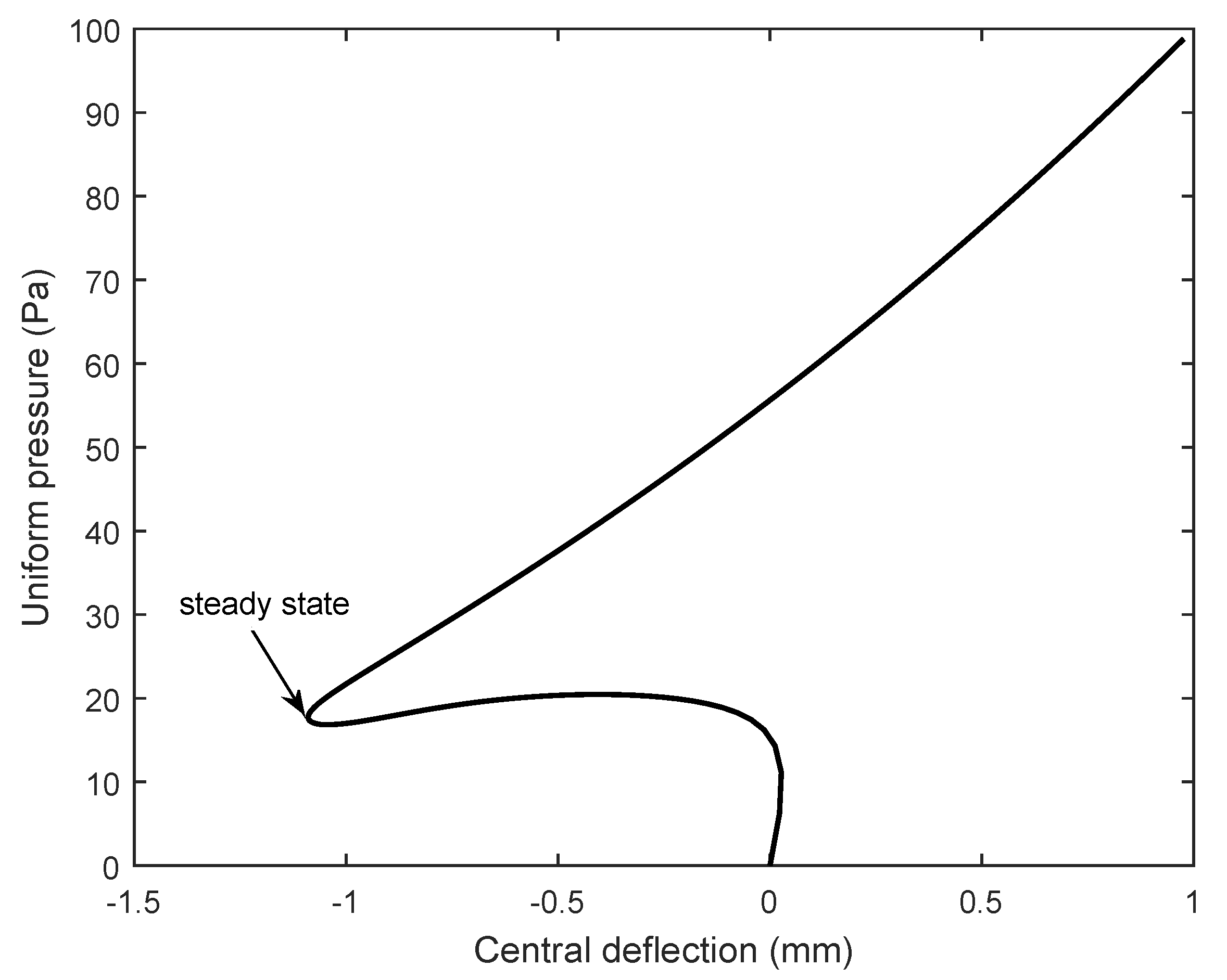
Figure 6.
Central deflection of the fully clamped isotropic cylindrical membrane with mm, .

Figure 7.
Effect of CNTs distribution on nonlinear response of the fully clamped FG-CNTRC cylindrical membrane with , mm, .
Figure 7.
Effect of CNTs distribution on nonlinear response of the fully clamped FG-CNTRC cylindrical membrane with , mm, .

Figure 8.
Effect of volume fraction on nonlinear response of the fully clamped FG-CNTRC cylindrical membrane with mm, , UD distribution.
Figure 8.
Effect of volume fraction on nonlinear response of the fully clamped FG-CNTRC cylindrical membrane with mm, , UD distribution.

Figure 9.
Effect of CNTs distribution on nonlinear response of the fully clamped FG-CNTRC cylindrical membrane with , mm, .
Figure 9.
Effect of CNTs distribution on nonlinear response of the fully clamped FG-CNTRC cylindrical membrane with , mm, .

Figure 10.
Effect of CNTs distribution on nonlinear response of the fully clamped FG-CNTRC square membrane with , mm, .
Figure 10.
Effect of CNTs distribution on nonlinear response of the fully clamped FG-CNTRC square membrane with , mm, .

Figure 11.
Effect of curvature on nonlinear response of the fully clamped FG-CNTRC cylindrical membrane with mm, , UD distribution.
Figure 11.
Effect of curvature on nonlinear response of the fully clamped FG-CNTRC cylindrical membrane with mm, , UD distribution.

Figure 12.
Meshes of 14 × 14 elements of FG-CNTRC membranes with various curvatures. (a) , (b) .

Figure 13.
Effect of thickness on nonlinear response of the fully clamped FG-CNTRC cylindrical membrane with , , UD distribution.
Figure 13.
Effect of thickness on nonlinear response of the fully clamped FG-CNTRC cylindrical membrane with , , UD distribution.

Figure 14.
A fully clamped composite circular cylinder subjected to an internal pressure, ABCD is one eighth of the cylinder.
Figure 14.
A fully clamped composite circular cylinder subjected to an internal pressure, ABCD is one eighth of the cylinder.

Figure 15.
Central radial deflection of a fully clamped composite cylinder with , .

Figure 16.
Normalized central radial deflections of clamped FG-CNTRC cylinder shells/membranes under external pressure with and . (a) Cylinder shells, , (b) cylinder membranes, .
Figure 16.
Normalized central radial deflections of clamped FG-CNTRC cylinder shells/membranes under external pressure with and . (a) Cylinder shells, , (b) cylinder membranes, .

Figure 17.
Normalized central radial deflections of clamped FG-CNTRC cylinder membranes under external pressure with , , UD distribution, various .
Figure 17.
Normalized central radial deflections of clamped FG-CNTRC cylinder membranes under external pressure with , , UD distribution, various .

Figure 18.
Normalized central radial deflections of clamped FG-CNTRC cylinder shells/membranes under external pressure with , , UD distribution, various .
Figure 18.
Normalized central radial deflections of clamped FG-CNTRC cylinder shells/membranes under external pressure with , , UD distribution, various .

Figure 19.
Normalized central radial deflections of clamped FG-CNTRC cylinder shells/membranes under external pressure with , UD distribution, various . (a) Cylinder shells, , (b) cylinder membranes, .
Figure 19.
Normalized central radial deflections of clamped FG-CNTRC cylinder shells/membranes under external pressure with , UD distribution, various . (a) Cylinder shells, , (b) cylinder membranes, .

Publisher’s Note: MDPI stays neutral with regard to jurisdictional claims in published maps and institutional affiliations. |
© 2022 by the authors. Licensee MDPI, Basel, Switzerland. This article is an open access article distributed under the terms and conditions of the Creative Commons Attribution (CC BY) license (https://creativecommons.org/licenses/by/4.0/).
Share and Cite
MDPI and ACS Style
Nguyen, T.N.; Dang, L.M.; Lee, J.; Nguyen, P.V. Load-Carrying Capacity of Ultra-Thin Shells with and without CNTs Reinforcement. Mathematics 2022, 10, 1481. https://doi.org/10.3390/math10091481
AMA Style
Nguyen TN, Dang LM, Lee J, Nguyen PV. Load-Carrying Capacity of Ultra-Thin Shells with and without CNTs Reinforcement. Mathematics. 2022; 10(9):1481. https://doi.org/10.3390/math10091481
Chicago/Turabian StyleNguyen, Tan N., L. Minh Dang, Jaehong Lee, and Pho Van Nguyen. 2022. "Load-Carrying Capacity of Ultra-Thin Shells with and without CNTs Reinforcement" Mathematics 10, no. 9: 1481. https://doi.org/10.3390/math10091481
Note that from the first issue of 2016, this journal uses article numbers instead of page numbers. See further details here.