Article

Design and Analysis of Guidance Function of Permanent Magnet Electrodynamic Suspension

1
School of Mechanical Engineering, Southwest Jiaotong University, Chengdu 610031, China
2
State Key Laboratory of Traction Power, Southwest Jiaotong University, Chengdu 610031, China
3
Research Center for Super-High-Speed Evacuated Tube Maglev Transport, Southwest Jiaotong University, Chengdu 610031, China
4
School of Information Science and Technology, Southwest Jiaotong University, Chengdu 610031, China
5
School of Electrical Engineering, Southwest Jiaotong University, Chengdu 610031, China
*
Author to whom correspondence should be addressed.
Technologies 2023, 11(1), 3; https://doi.org/10.3390/technologies11010003
Submission received: 9 November 2022 / Revised: 16 December 2022 / Accepted: 18 December 2022 / Published: 21 December 2022
(This article belongs to the Section Assistive Technologies)

Abstract

:
Inspired by the guidance principle in the electromagnetic levitation system, a new permanent magnet electrodynamic suspension (PM EDS) structure with ferromagnetic guidance track is proposed and analyzed in this paper. Considering the lack of effective guidance ability for the PM EDS system, we adopted the ferromagnetic guidance track as being mounted under the conductor plate. The guidance principle is studied and the implementation of the guidance function is also introduced, and the finite element method (FEM) is employed and its accuracy is confirmed via the PM EDS high-speed rotating experimental platform fabricated in our laboratory. The influence of longitudinal speed on the guidance force is taken into account, which shows that the guidance performance is enhanced more obviously at low speeds. Moreover, the influence of the guidance track parameters on the guidance performance is also analyzed, including the geometric parameters, section shape, installation position and material. The equivalent small-scale PM EDS system experimental prototype is carried out to validate the effectiveness of the ferromagnetic guidance. The proposed ferromagnetic guidance structure is demonstrated to improve the guidance performance of the PM EDS system effectively, which will offer a technical reference for the practical engineering application of the PM EDS system.

1. Introduction

As the concept of whole speed range (WSR) is proposed, the magnetic levitation (maglev) rail transport is supposed to be developed to make up for the speed gap between the high-speed railway and air passenger transport [1]. Due to the merits of wide speed range, low noise and low maintenance cost, the maglev train is a very competitive green ground transportation tool [2,3]. Based on the levitation principle, the maglev technologies can be divided into four forms: permanent magnetic suspension (PMS) [4,5], electromagnetic suspension (EMS) [6,7], electrodynamic suspension (EDS) [8,9] and flux pining suspension (FPS) [10,11]. Among them, the electrodynamic suspension is further divided into permanent magnet electrodynamic suspension (PM EDS) and superconducting electrodynamic suspension (SC EDS). Since the PM EDS has several advantages, such as simple structure, low cost, adaptive height levitation, no active control requirement, large levitation gap, etc., it has good application prospects in rail transport and other transportation fields. Although EDS systems are usually considered to be inherently stable, there are a variety of factors, including perturbations and track irregularity, that may lead to unstable responses [12]. Therefore, PM EDS is an under-damped, or even an undamped, system [13]. To address this issue, there are many research institutions and scholars focused on improving the stability of the maglev train.
Based on the published papers, the guidance methods applied in maglev train can be generalized to three categories, including mechanical wheel auxiliary guidance, electromagnetic attractive guidance and electrodynamic repulsive guidance. Mechanical wheels are often used in maglev trains for support and guidance [14]. Through the rolling friction between the on-board guidance wheel and guidance rail, a guidance force will be produced to keep the train in alignment. However, due to the major friction and wear, the mechanical wheel is not suitable for high-speed maglev trains. Therefore, the non-contact guidance methods appear gradually. EMS systems, such as the German TR series train [15], consist of suspension and guidance electromagnet, carriage, suspension device and bogie. The electromagnetic attractive guidance function is achieved by adding an additional guidance electromagnet. The interaction between suspension electromagnet and ferromagnetic track will generate the suspension force, while the interaction between the additional guidance electromagnet and track will produce a guidance force. However, the guidance electromagnet will increase the difficulty of the control system, which is essentially the hard part of the EMS system. In addition, the additional auxiliary equipment will also add to the cost. The research of electromagnetic attractive guidance technology mainly focused on the analytical calculation and simulation of the guidance force and the control methods of guidance systems [16,17,18,19]. As with the electrodynamic repulsive guidance technology, according to the different magnetic field sources, it can be divided into PM or SC electrodynamic repulsive guidance. In terms of the SC-EDS system, such as the Japanese MLX superconducting maglev train [20], the 8-shape coils are used to realize guidance function. When the train is deviated horizontally, due to the different gaps between the on-board SC magnets and the coils on both sides, the guidance force generated on the side with a small gap is greater than that on the other side. Additionally, the overall performance is a recovery force to bring the train back to its original position. The relevant research work is mainly the analytical calculation and simulation of the guidance force [21,22]. For the PM EDS system, there are two main ways to improve the guidance performance. One is to change the section shape of the track, such as the Magplane [23] proposed by Montgomery of the Massachusetts Institute of Technology (MIT). The part of the electromagnetic force generated by the arc-shaped track acts as the guidance force to implement the guidance function. Other section shapes of the track, such as the V-shape, are also adopted. However, this guidance function is unstable and has low reliability. The other is like the guidance scheme of the EMS system, which mounts additional guidance PM arrays on each side of the train [24,25]. The resultant force of the repulsion forces generated on both sides guarantees the train in alignment. However, due to the inherent instability of the PM EDS system, the difficulty of the control system will increase. The additional guidance PM arrays will also add more cost.
Based on the above research, there is no simple or low-cost method to improve the guidance performance of the PM EDS system. As a solution, we develop a new PM EDS structure with the Halbach array of simple construction, which adopts the additional ferromagnetic guidance track. The guidance force generated by the PM and guidance track is demonstrated to improve the guidance performance effectively. The proposed new structure will offer a technical reference for the practical engineering application of the PM EDS system. The levitation and guidance operation principles are explained in Section 2. The accuracy of FEM is verified in Section 3, according to the PM EDS high-speed rotating experimental platform developed in our laboratory. The guidance performance is analyzed and the optimization of the guidance track is conducted in Section 4. The annular PM EDS experimental prototype is developed to verify the effectiveness of the ferromagnetic guidance in Section 5.

2. Operation and Principles

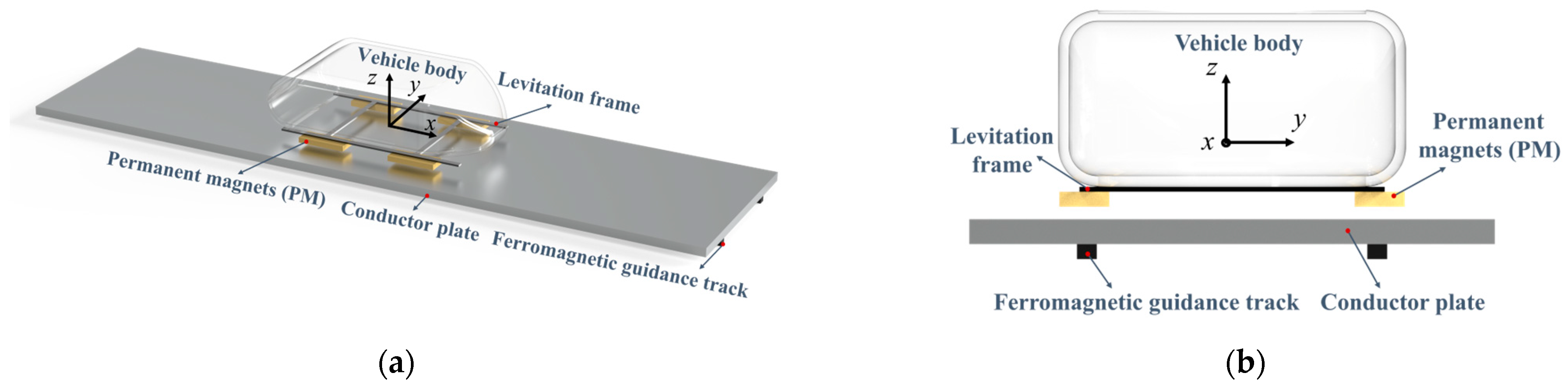
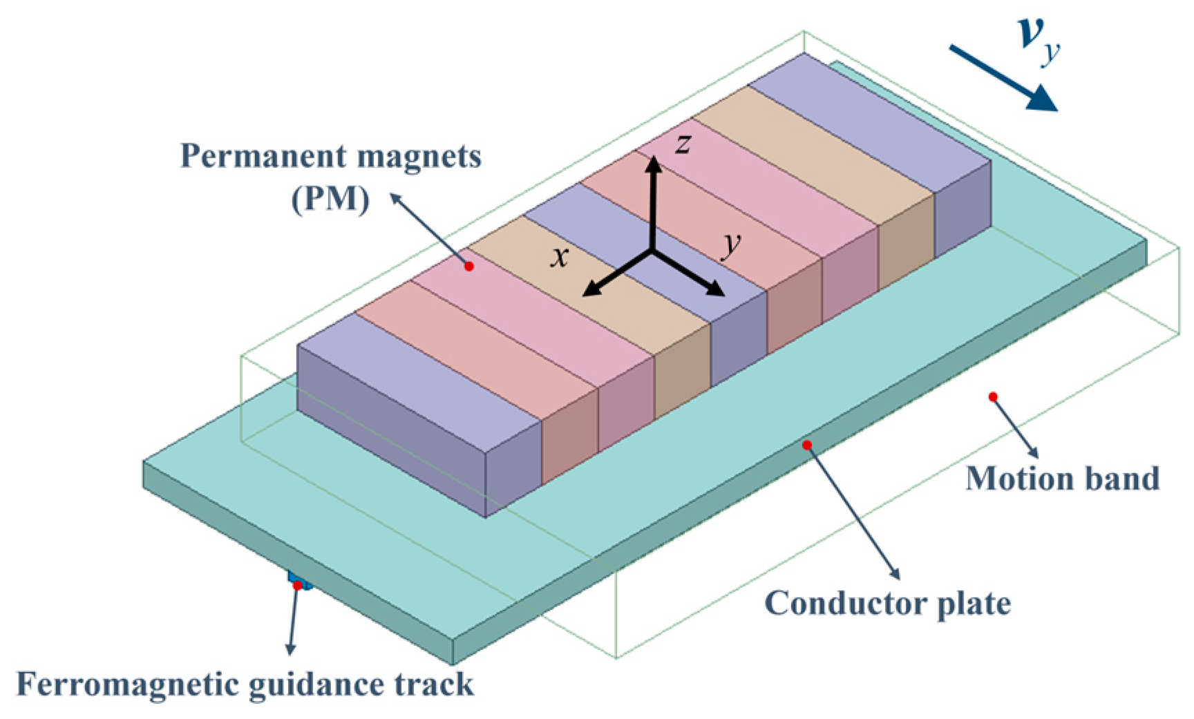
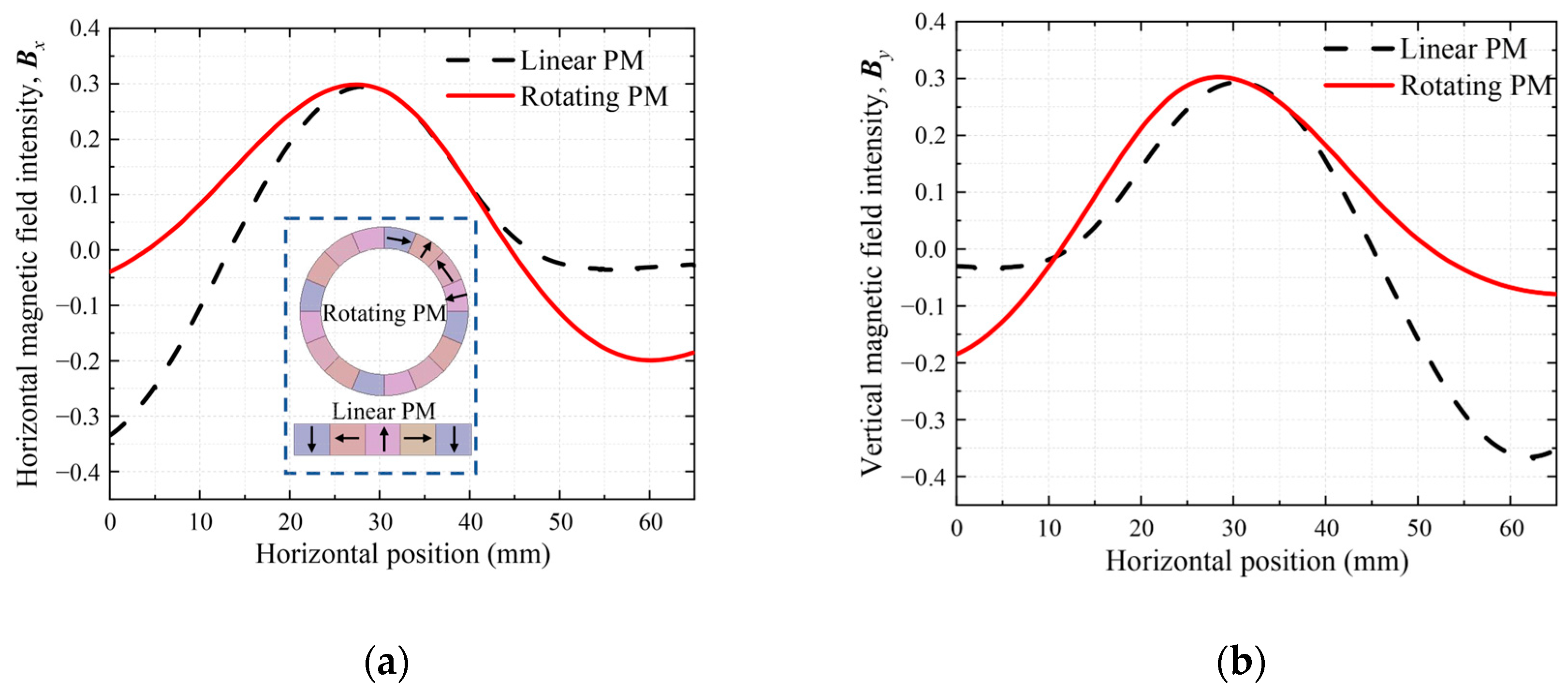
2.1. Presentation of a New Structure

A new EDS structure is proposed by combining permanent magnets, a conductor plate and a ferromagnetic guidance track, as shown in Figure 1. The guidance tracks are laid under the conductor plate along the x axis for easy installation; x axis is the vehicle moving direction, y axis is the transverse direction and z axis is the vertical direction (vehicle levitation direction). The vehicle body is mounted above the levitation frame and PM are arranged as Halbach array underneath the levitation frame. To ensure stability, four groups of PM are used in one carriage of the vehicle. The non-ferromagnetic metal conductor plate is laid along the road surface. The linear motor for propulsion is omitted here as it is not the core part of this new structure.

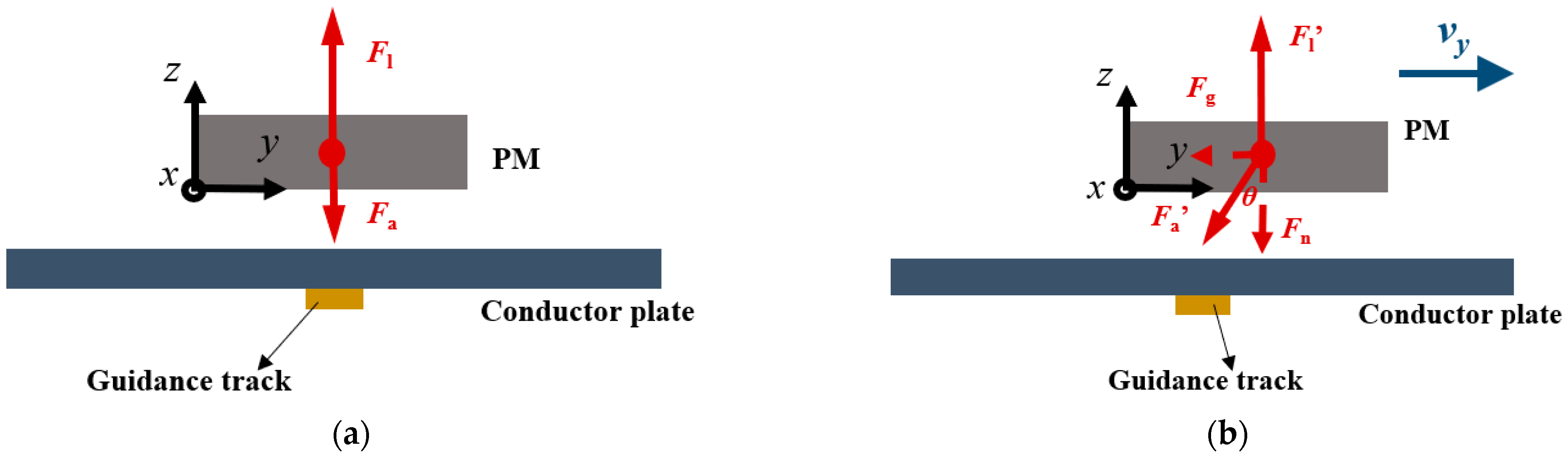
2.2. Basic Principles of the New Structure

Based on the electromagnetic induction principle, when the on-board PM moves along the conductor plate, the relative motion will generate induced eddy current in the plate. The surface density of the induced current can be expressed as [26]:
J = −σvB
where J is the current density in the conductor plate, σ is the electrical conductivity of the plate, v is the moving speed and B is the magnetic field intensity of the PM.
The interaction between the PM magnetic field and the magnetic field induced by the eddy current will generate an electromagnetic repulsive force. Based on the Lorentz’s theorem, the electromagnetic force takes the form:
F = J × B
The vertical component of this force is levitation force while the horizontal component is drag force. When the moving PM reaches a certain speed, the levitation force is greater than the vehicle gravity and the system can realize the levitation operation.
In order to realize the guidance function, the ferromagnetic guidance track is adopted. It will interact with the PM to generate an electromagnetic attraction force, Fa. In normal conditions, the PM and the guidance track are in alignment, and the force analysis of the PM is shown in Figure 2a. The direction of the attraction force is vertically downward, which will cancel part of the levitation force, Fl. When the vehicle exists transverse displacement, the PM will deviate from the guidance track at a certain speed v, and the force analysis of the PM is shown in Figure 2b. The direction of the attraction force Fa’ is oblique downward, and its component in the vertical direction Fn as a normal attraction force will consume part of the levitation force Fl’. Additionally, the component in the horizontal direction Fg will be taken as a guidance force to restore the vehicle’s return to the centered running state. The relationship between Fn, Fg and Fa’ can be expressed as follows:
Fn = Fa’cosθ
Fg = Fa’sinθ
where θ is the angle between the attraction force and the vertical direction.

3. FEM Experimental Verification

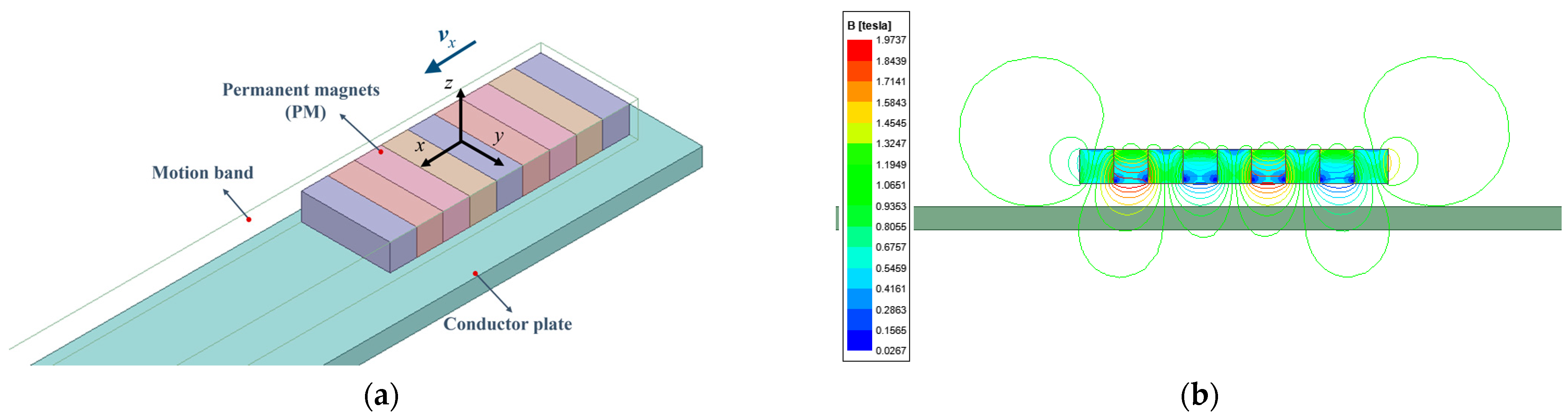
3.1. Establishment of Finite Element Model

According to the parameters in Table 1, the finite element model of the PM EDS system is established by Ansys Maxwell, which is shown in Figure 3. The following simulation analysis is conducted at a constant speed along axis x without electrodynamic terms in axes y and z.

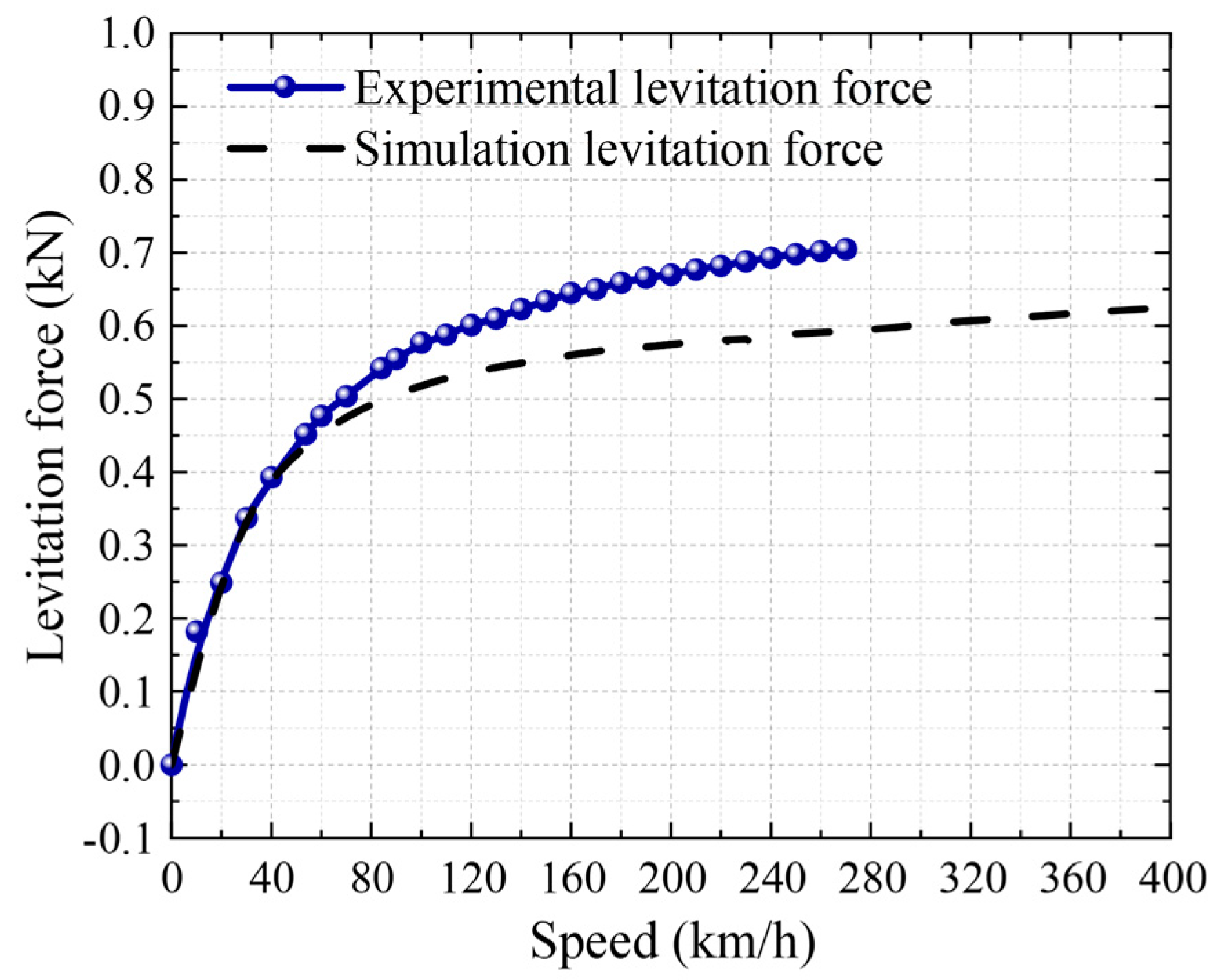
3.2. Experimental Verification

The FEM is adopted to analyze the system performance, hence it is necessary to verify the accuracy of FEM. According to the parameters in Table 1, the PM EDS high-speed rotating experimental platform has been designed and constructed in our laboratory [27]. As seen in Figure 4, the facility is composed of a conversion timing AC motor, brake system, transmission mechanism, PM, circular aluminum track, measurement system, monitor platform and cooling system. The linear motion of vehicle-mounted magnets can be equivalent to the rotating motion of the aluminum track. Two servo motors are connected with the measurement system, and the sliding platform mechanism is driven by the servo motor to adjust the electromagnetic gap accurately. As the circular aluminum track rotates at different speeds and levitation gaps, the measurement system can record the levitation, drag and guidance force acting on the PM in real time, and it can visualize them on the monitor platform for storage. In order to ensure the reliability of the experimental results, the speed accuracy of the track is lower than 1% and the positioning accuracy is 0.01 mm.

3.3. Results Comparison

The simulation and experiment are both carried out at the levitation gap of 25 mm, and the results of forces are shown in Figure 5. The levitation forces increase monotonically with the operating velocity but tend asymptotically to a maximum value. According to the comparison between simulated and experimental data, it can be found that the force test result has the same trend as the simulation. The reasons for the numerical error are presumed to be the differences in track conductivity. In addition, the linear motion of the PM is equivalent to the rotational motion in an experimental device. The equivalent method will also produce the error. In addition, the temperature rise of the aluminum track during the experiment will also affect the experimental results. In general, the experimental results basically match the simulation results. The accuracy of FEM has been verified, and it can be employed to carry out the next part of the optimization work.

4. Analysis on Guidance Performance and Parameter Optimization

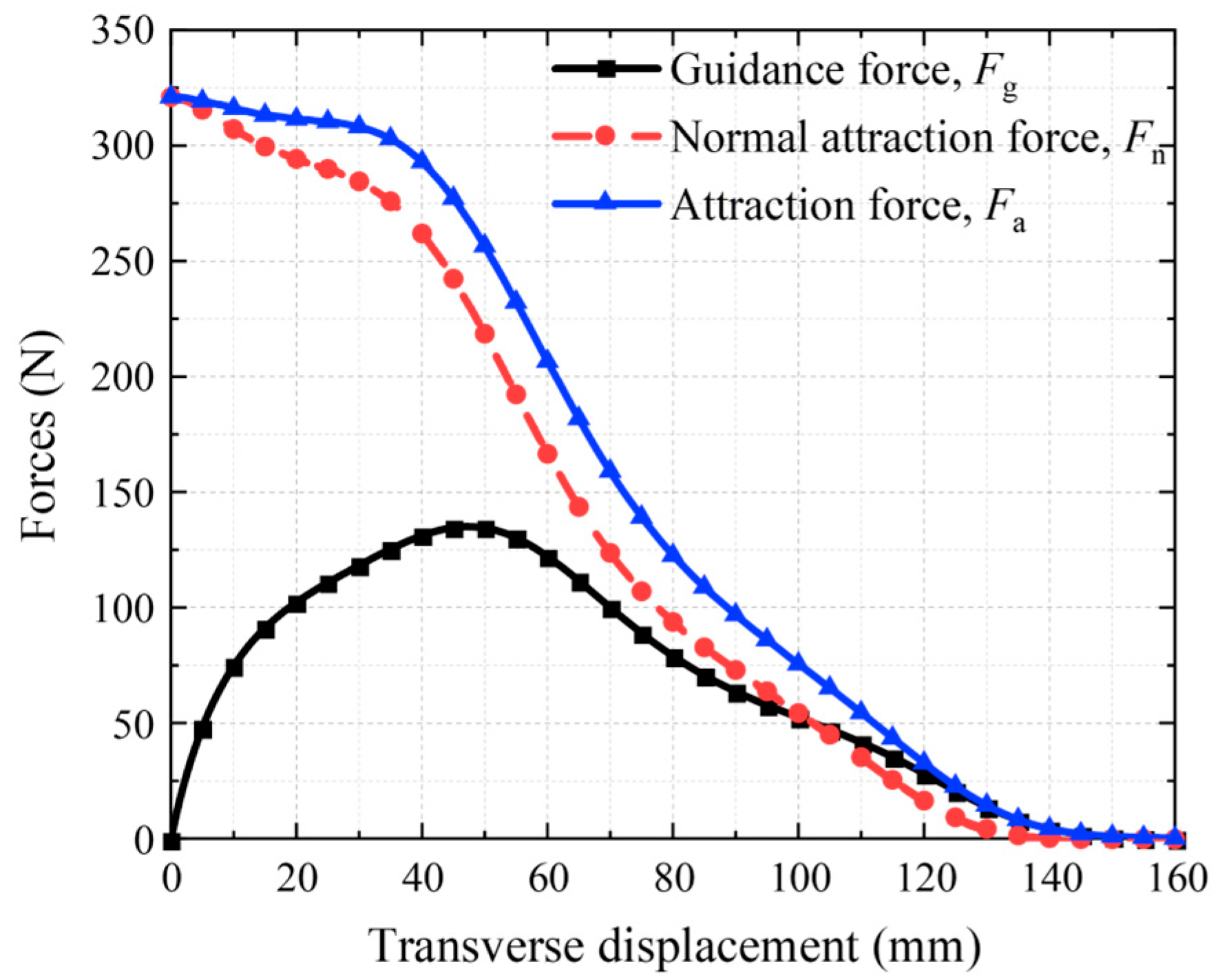
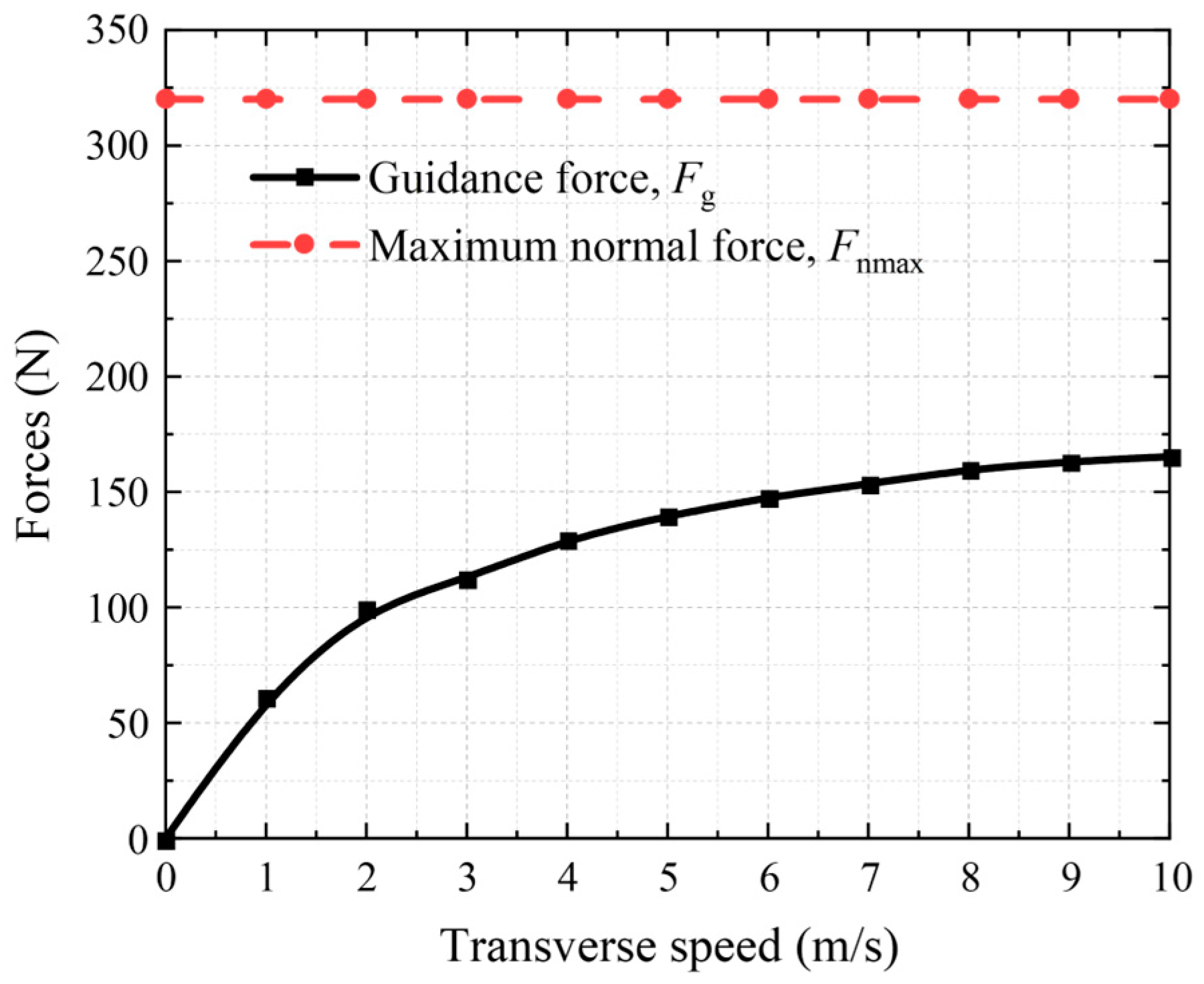
4.1. Guidance Performance Analysis

The finite element model of the guidance system was built (as shown in Figure 6); its parameters are shown in Table 2. The simulation calculation condition is that the PM deviates from the center of the conductor plate to the transverse direction at a certain speed. With the transverse movement of PM, the implementation of the guidance function relies on the attraction force between the PM and the guidance track. Meanwhile, the guidance force and normal attraction force vary with the transverse displacement, as shown in Figure 7. The positive directions of the guidance force and normal attraction force are opposite to the transverse displacement and are downward vertically, respectively. The trend of guidance force firstly increases and then decreases with the transverse displacement, while the trends of attraction force and normal attraction force are continually in decline. When the transverse displacement is large (such as more than 120 mm), due to the large distance between the PM and the guidance track, the attraction force between them is extremely small and can be ignored. Then, the force on the PM is mainly the electromagnetic force due to the edge effect. Thus, the guidance force, normal attraction force and attraction force decline as an exponential trend. Since the edge of the PM is 32.5 mm away from the edge of the conductor plate, we chose the average of the guidance force generated within the 32.5 mm transverse displacement as the guidance force of the system.
The guidance force and maximum normal force, which represent the guidance performance, are acquired at different transverse speeds, and working gaps are shown in Figure 8. With the increase in transverse speed, the maximum normal force remains constant. This is because the attraction force generated by the PM and ferromagnetic material only depend on the distance between them. The smaller the distance is, the greater the attraction force is. The working gap at the initial central position is the minimum, so the attraction force reaches the maximum, and at this point, the direction of the attraction force is vertically downward, known as the normal attraction force. As for the guidance force, it increases linearly firstly and then tends to be stable as the transverse speed rises. Given that the attraction force is irrelevant to the transverse speed, the reason for the guidance force varying with the transverse speed is that the existence of the electromagnetic force generated by the lateral movement of PM is due to the edge effect. The guidance force provided only by the horizontal component of the attraction force does not vary with the transverse speed. Figure 9 shows the variation in guidance and maximum normal forces with the working gap. As mentioned, with the increase in working gap, both of forces show a decreasing trend. The maximum normal force decreases even more. Therefore, an appropriate increase for working gap can be a trade-off between the guidance force and the normal attraction force.
In the practical application of PM EDS system, both the transverse displacement and longitudinal displacement should also be considered to analyze its stability. So, in this paper, the influence of the longitudinal speed is also taken into account. The variation in attraction force with longitudinal speed is shown in Figure 10. As the longitudinal speed increases, the attraction force decreases, and the enhancement of the guidance performance is less obvious. The results show that the guidance track can also provide partial guidance force at high speeds. This paper aims to analyze the transverse instability of the PM EDS system and to verify the effectiveness of the guidance track. The following established simulation models only consider the transverse displacement at zero longitudinal speed to evaluate the guidance performance.

4.2. Parameters Optimization Analysis

In order to improve guidance performance, the influence factors, including geometric parameters, section shape, installation position and the material of guidance track, are supposed to be optimized. Several optimization indexes are defined as the measurement criteria. The guidance-to-weight ratio (G-Wratio), which denotes the guidance capability of the system can be obtained as follows:
G-Wratio = Fg/Weight
The guidance-to-maximum normal attraction ratio (G-Aratio) reflects the guidance comprehensive performance of the guidance track; it is defined as:
G-Aratio = Fg/Fnmax
The purpose of optimization is to maximize the G-Wratio and G-Aratio. The following optimization work is carried out at a transverse speed of 2 m/s and a suspension gap of 15 mm.

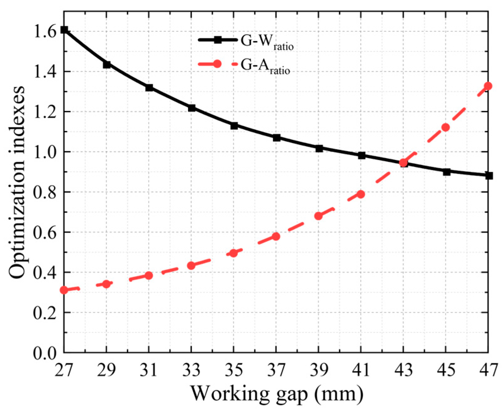
4.3. Geometric Parameters Analysis

The width and thickness parameters of the guidance track are important in the guidance system, which will affect the guidance performance directly. The simulation optimization is conducted with a width range of 10 to 40 mm, and a thickness in the range of 2 to 10 mm. The results of the optimization indexes are shown in Figure 11 and Figure 12. Based on the principle that the larger the width and thickness are, the greater the attraction force is, Figure 11 shows that the G-Wratio increases with the width and thickness of the guidance track. Obviously, the width has a greater gain effect on the attraction force than that under influence of the thickness. As seen in Figure 12, the G-Aratio is decreasing with the width and thickness, which means that the geometric parameters increase, and the normal attraction force increases more than the guidance force. Additionally, the G-Aratio decreases much more obviously under the width increase than under the thickness increase. In conclusion, the width of the guidance track has more obvious influence on guidance performance than thickness. The reason for this rule is that the area of interaction between the guidance track and PM increases with the increasing width. Therefore, smaller thickness can be selected based on cost considerations and larger width can be selected to ensure the guidance performance.

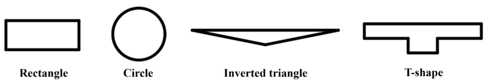
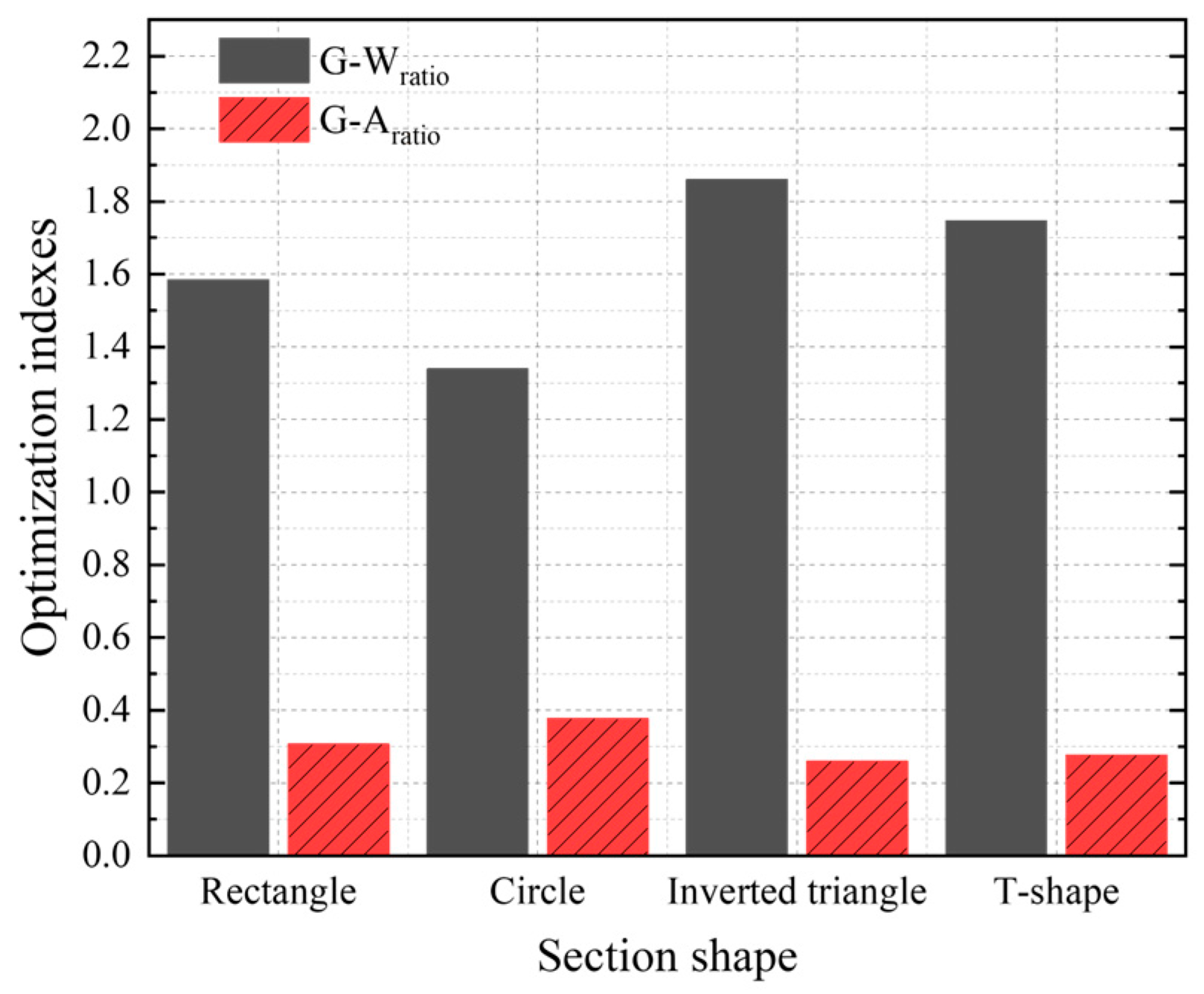
4.4. Shape Section Analysis

Based on analysis of Section 4.3, the different interaction area will lead to a different guidance performance. It can be inferred that under the condition of the same volume, for the different section shapes of the guidance track, the magnitude of the attraction force is also different. According to the influence law of the working gap between the PM and ferromagnetic material on attraction force, the upper surface area of the guidance track has greater influence on the guidance performance. Hence, we built the simulation models with different section shapes (as shown in Figure 13), such as rectangle, circle, inverted triangle and T-shape; the results of the optimization indexes are shown in Figure 14. In contrast to the other section shapes, the inverted triangle shape has the biggest G-Wratio and the lowest G-Aratio. So, it is beneficial to improve the guidance capability, but it also increases the normal attraction force. The circle shape has the largest G-Aratio and the lowest G-Wratio; thus, it cannot provide sufficient guidance capability. Taking into account the synthesis of the indexes and the installation and maintenance cost, the appropriate section shape can be chosen according to the above rules.

4.5. Installation Position Analysis

To ensure that the direction of attraction force is straight down when the vehicle is running in alignment, the guidance track should be installed in the middle of the conductor plate and laid along with the plate. Based on the analysis of the guidance performance in Section 4.1, the guidance force and the maximum normal force are related to the working gap. So, the vertical installation position of the guidance track in the conductor plate can be optimized to obtain a better guidance performance. The optimization indexes are calculated at the working gap in the range of 27 to 47 mm when the guidance track width is 18 mm and thickness is 2 mm. The optimized results are shown in Figure 15; we can find that the G-Wratio decreases synchronously with the increment of the working gap. On the contrary, the G-Aratio is on an increasing trend. To guarantee the sufficient guidance capability and as small a normal attraction force as possible, the appropriate working gap can be selected for different conditions.

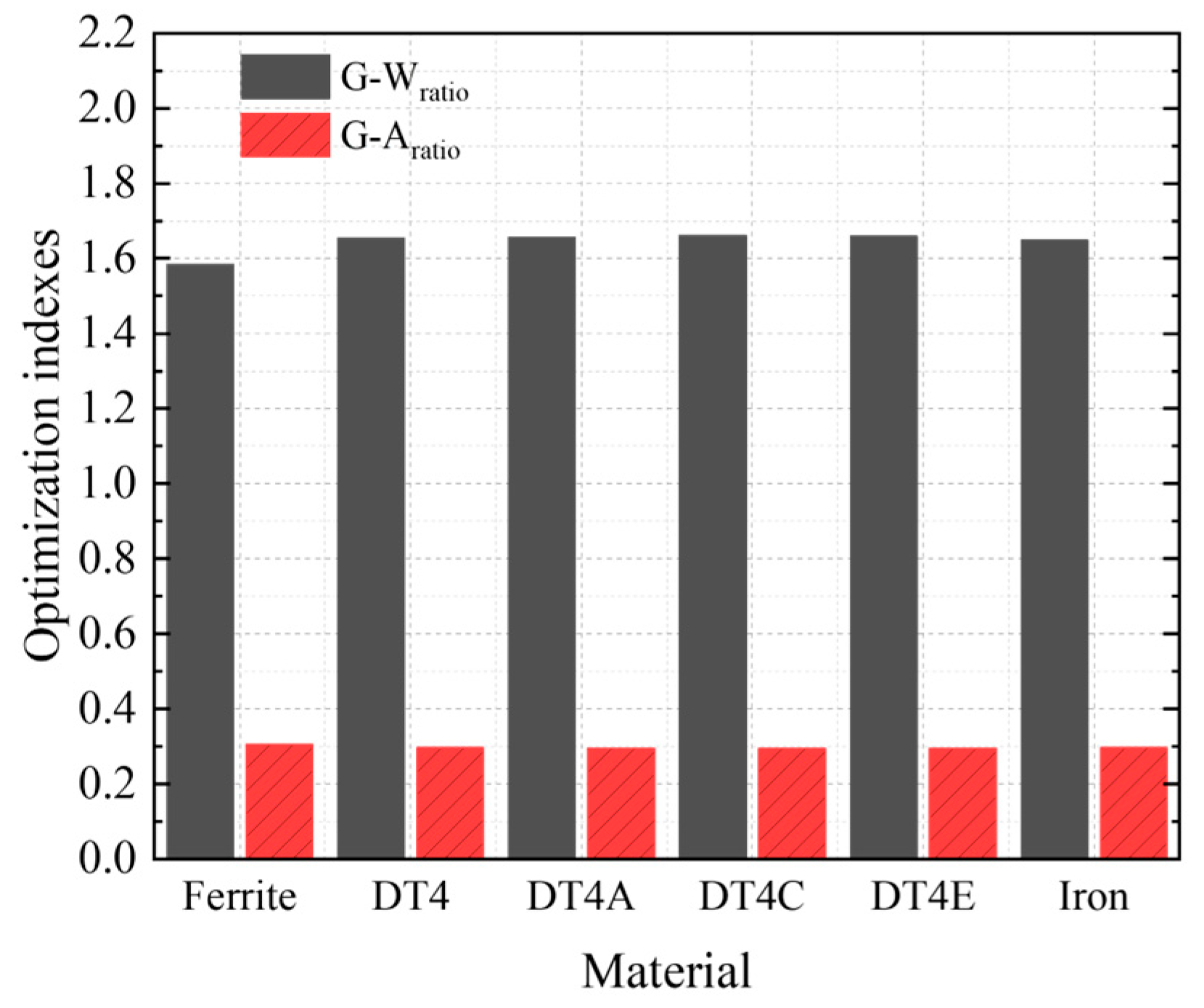
4.6. Material Selection Analysis

For the common ferromagnetic materials, the different material designations will generate different guidance performances. As shown in Figure 16, there is almost no difference for the optimization indexes of different ferromagnetic materials. DT4C has the greatest G-Wratio and the lowest G-Aratio, while ferrite has the greatest G-Aratio and lowest G-Wratio. Additionally, pure iron shows better comprehensive performance, but it also has a softer texture, which is not appropriate for applications. Hence, considering the practical application and the installation and maintenance cost, the adequate ferromagnetic material can be chosen for the PM EDS system.

5. Equivalent Experimental Verification

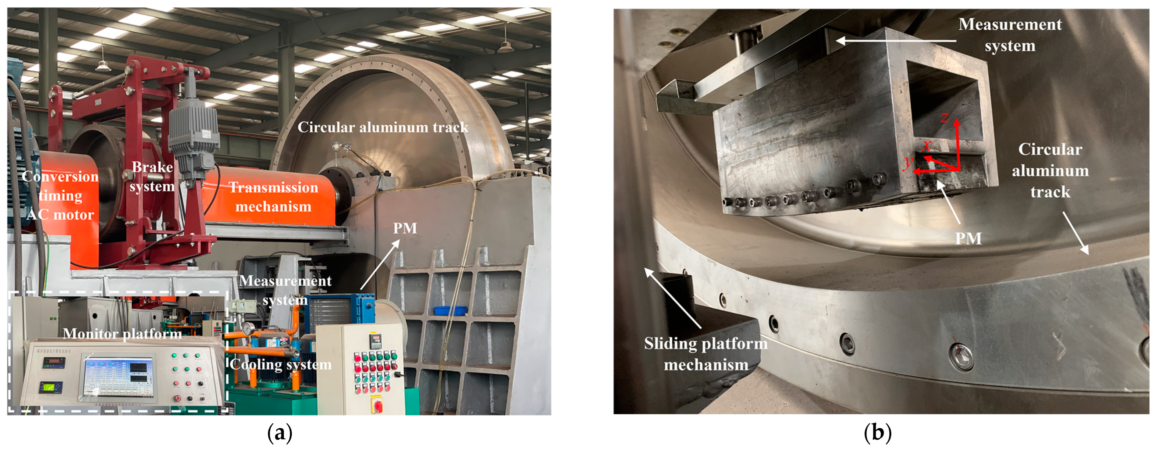
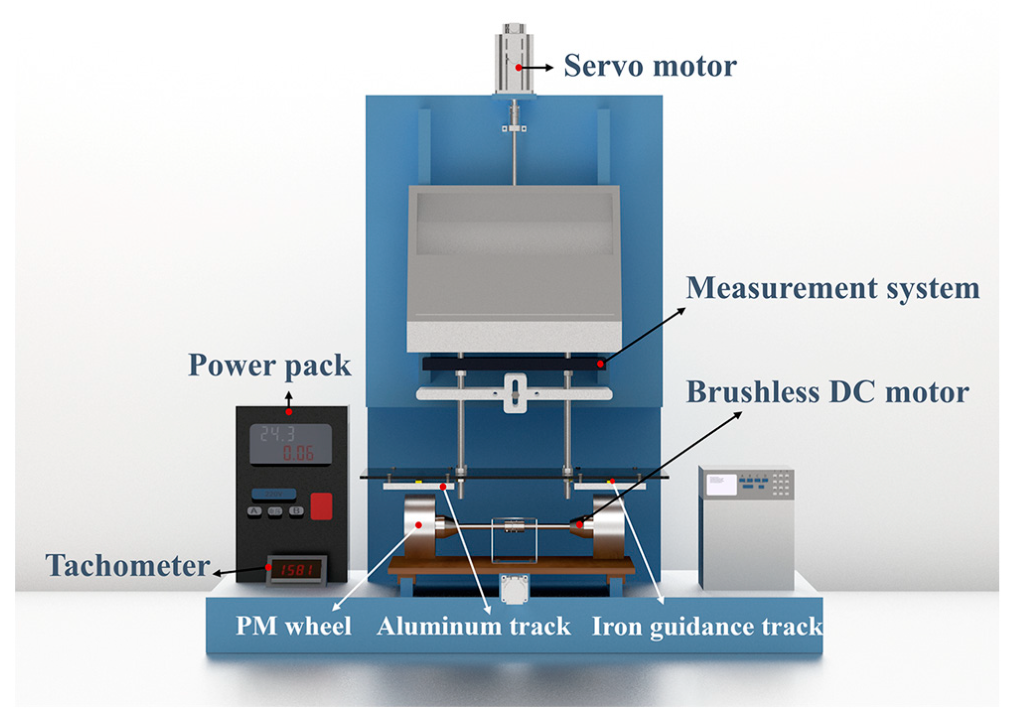
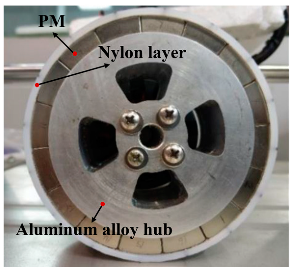
5.1. Experimental Prototype

To verify the effectiveness of the proposed structure, due to the limitations of the current experimental basis and hardware conditions, a small-scale annular PM EDS experimental prototype is established in our laboratory. Since the linear Halbach array EDS structure requires more auxiliary equipment and occupies a large experimental space, it is equivalent to using the rotating PM wheel. According to the parameters in Table 3, the simulation models of linear Halbach PM and equivalent rotating PM wheel are established, and the magnetic field intensity contrasts between them are shown in Figure 17. The horizontal and vertical magnetic field intensity distributions of the equivalent rotating PM wheel are basically consistent with that of the linear PM. Therefore, the equivalent method is verified preliminarily and it can be employed to carry out the experimental verification work.
As seen from Figure 18, the annular PM EDS experimental prototype consists of PM wheel, aluminum track, iron guidance track, brushless DC motor, servo motor, measurement system, power pack and tachometer. The iron guidance track is mounted away from the PM wheel side, on the top of the aluminum track. The specific design parameters of the annular PM EDS experimental prototype are shown in Table 4. The parameters of the guidance track are determined after optimization according to the PM wheel. When the PM wheel is driven by the motor under different speeds and levitation gaps, the forces can be acquired by the measurement system. In addition, the aluminum track can be translated laterally to test the guidance force. The physical picture of the equivalent rotating PM wheel is shown in Figure 19.

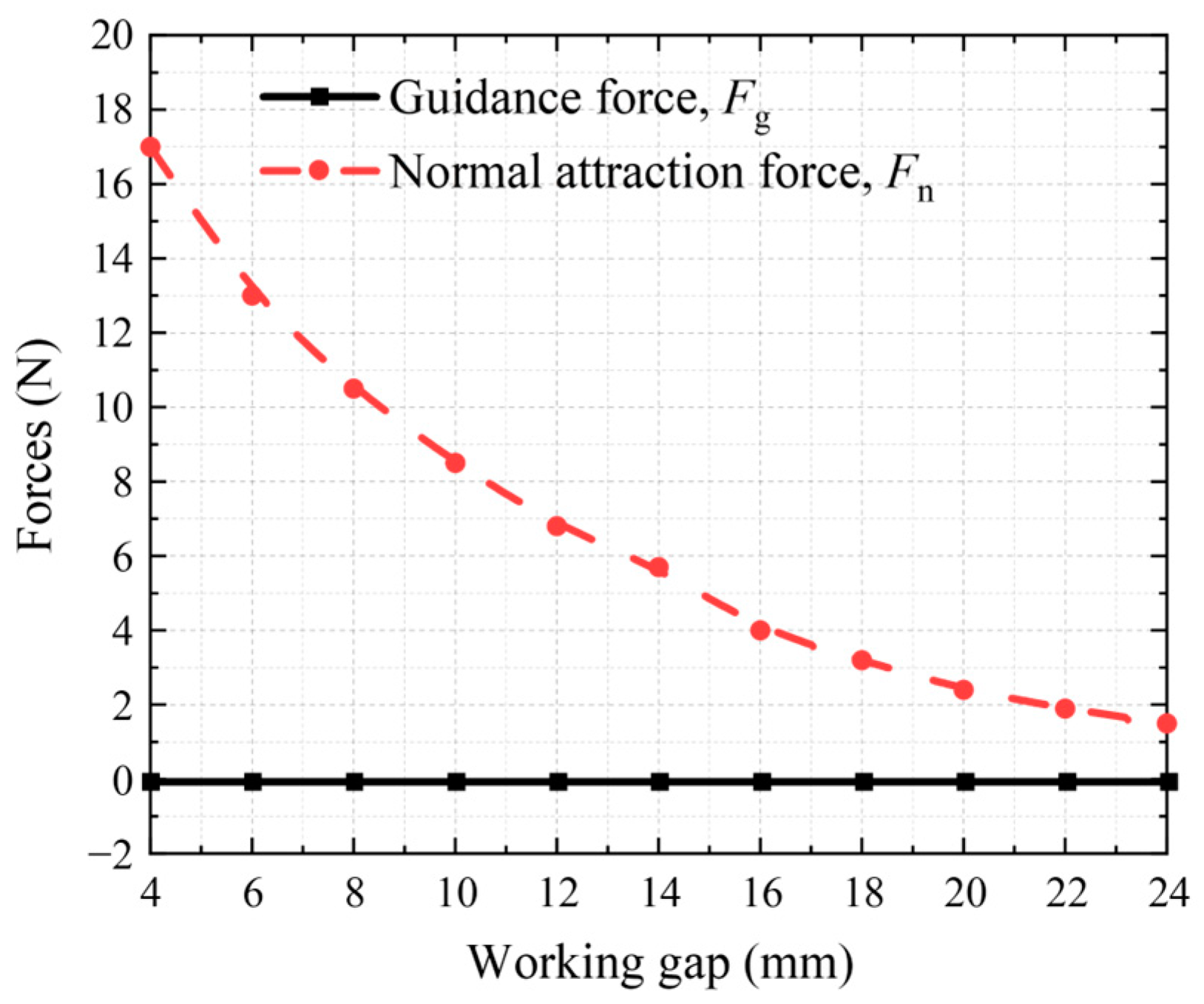
5.2. Analysis of Experimental Results

As the iron guidance track is installed, when the wheel is stationary and the track moves vertically, the variations in normal attraction force and guidance force are shown in Figure 20. Owing to the wheel that is in alignment with the track, the guidance force maintains zero with the increment of the working gap, while the attraction force is in decline. It is consistent with the above analysis.
As the iron guidance track is not installed, when the wheel rotates under different speeds and keeps the track stationary, the levitation and guidance forces are demonstrated in Figure 21. The levitation force increases monotonically with the operating velocity but tends asymptotically to a maximum value. However, due to the limitation of experimental conditions, the rotating speed only reached 3000 rpm, and the levitation force did not reach the maximum value. Meanwhile, due to the limited width of the aluminum track, there exists a lateral force, and the direction is negative. The lateral force is generated by the edge effect, which will push the PM wheel out of the track and lead to instability in the system. If a sufficiently wide track is used, the lateral force will almost be zero when the wheel rotates in alignment with the track.
When the PM wheel rotates at a constant speed and the track translates at a constant speed (with and without guidance track), the comparison of the guidance force is shown in Figure 22. When the transverse displacement is 0 mm, the PM wheel is aligned with the aluminum track, and the guidance force with installed guidance track is zero. On the contrary, the guidance force without the installed guidance track is not zero, and the direction of it is negative due to the edge effect, which will push the wheel out of the track. It shows that when the guidance track is installed, the lateral force of the system at the center position is zero so that stable levitation can be realized. As the transverse displacement increases, with the guidance track installed, the direction of the guidance force is consistent with the movement direction of the track, which can be regarded as a restoring force to pull the PM wheel back to the original position. Firstly, the guidance force increases, and then it decreases with the transverse displacement, which is consistent with the mentioned simulation analysis. In summary, with the iron guidance track installed, the PM wheel can be levitated stably when it is aligned with the track and can be offered a reverse recovery force when the track moves transversely. So, it is demonstrated that the installed guidance track can provide a guidance force and enhance the guidance performance of the system.

6. Conclusions

Based on the lack of effective guidance ability for PM EDS system, a new PM EDS structure is proposed and analyzed in this paper. The core components include PM, conductor plate, and ferromagnetic guidance track installed under the plate. According to the attraction between the PM and ferromagnetic guidance track, the guidance force is generated. Compared with the classical PM EDS system, the guidance performance of the new structure is improved efficiently only by adding the guidance track. On the basis of maintaining the simple structure of the PM EDS system, it does not increase excessive cost and installation and maintenance difficulty. The guidance performance is analyzed by establish the finite element model of the guidance system. In order to analyze the influence of the guidance track parameters on the guidance performance, the geometric parameters, section shape, installation position and material are optimized based on the presentation of optimization indexes: G-Wratio and G-Aratio. According to the simulation results, the guidance track can provide a partial guidance force to assist in the guidance performance. The guidance force is close to zero at high speeds. The guidance performance may be further improved by increasing the number of PM bulks, etc. The effectiveness of the proposed structure is verified by building a small-scale annular PM EDS experimental prototype. It can be found from the results that the ferromagnetic guidance track is an effective way to improve the guidance performance of the PM EDS system. The guidance force can be provided and the guidance ability can be improved through the ferromagnetic guidance track. In future work, a full-scale linear PM EDS experimental prototype will be constructed to verify the optimization work, which will facilitate a deeper exploration of the proposed structure.

Author Contributions

Conceptualization, Y.X. and Z.D.; methodology, Y.X. and H.S.; software, Y.X., K.L. and T.C.; validation, Y.X. and H.S.; formal analysis, Y.X.; investigation, Y.X.; resources, Z.D., J.Z., B.D. and L.L.; data curation, Y.X.; writing—original draft preparation, Y.X.; writing—review and editing, Z.D., L.L., H.S. and B.D.; visualization, Y.X.; supervision, Z.D.; project administration, Z.D., J.Z. and L.L.; funding acquisition, Z.D. All authors have read and agreed to the published version of the manuscript.

Funding

This work was partially supported by the Sichuan Science and Technology Program (22CXTD0070), the Science and Technology Program of the Jiangsu Provincial Department of Transport (2021Y02), and the Fundamental Research Funds for the Central Universities (2682022CX062).

Data Availability Statement

Not applicable.

Conflicts of Interest

The authors declare no conflict of interest.

References

  1. Xu, F.; Luo, S.; Deng, Z. Study on key technologies and whole speed range application of maglev rail transport. J. China Railw. 2019, 41, 40–49. [Google Scholar] [CrossRef]
  2. Franca, T.N.; Shi, H.; Deng, Z.; Stephan, R.M. Overview of electrodynamic levitation technique applied to maglev vehicles. IEEE Trans. Appl. Supercon. 2021, 31, 3602605. [Google Scholar] [CrossRef]
  3. Luo, C.; Zhang, K.; Duan, J.; Jing, Y. Study of permanent magnet electrodynamic suspension system with a novel Halbach array. J. Elecrt. Eng. Technol. 2020, 15, 969–977. [Google Scholar] [CrossRef]
  4. Paden, B.A.; Snyder, S.T.; Paden, B.E.; Ricci, M.R. Modeling and control of an electromagnetic variable valve actuation system. IEEEASME Trans. Mechatron. 2015, 20, 2654–2665. [Google Scholar] [CrossRef]
  5. Zhao, C.; Sun, F.; Jin, J.; Pei, W.; Xu, F.; Oka, K.; Zhang, M. Research of permanent magnetic levitation system: Analysis, control strategy design, and experiment. Proc. Inst. Mech. Eng. Part C-J. Eng. Mech. Eng. Sci. 2022, 14, 7617–7628. [Google Scholar] [CrossRef]
  6. Hu, J.; Ma, W.; Chen, X.; Luo, S. Levitation stability and Hopf bifurcation of EMS maglev trains. Math. Probl. Eng. 2020, 2020, 2936838. [Google Scholar] [CrossRef]
  7. Ding, J.; Yang, X.; Long, Z. Structure and control design of levitation electromagnet for electromagnetic suspension medium-speed maglev train. J. Vib. Control 2019, 25, 1179–1193. [Google Scholar] [CrossRef]
  8. Lv, G.; Liu, Y.; Zhou, T.; Zhang, Z. Analysis of suspension and guidance system of EDS maglev based on a novel magnetomotive force model. IEEE J. Emerg. Sel. Top. Power Electron. 2022, 10, 2923–2933. [Google Scholar] [CrossRef]
  9. Hu, Y.; Long, Z.; Zeng, J.; Wang, Z. Analytical optimization of electrodynamic suspension for ultrahigh-speed ground transportation. IEEE Trans. Magn. 2021, 57, 1–11. [Google Scholar] [CrossRef]
  10. Deng, Z.; Li, J.; Zhang, W.; Gou, Y. High-temperature superconducting magnetic levitation vehicles: Dynamic characteristics while running on a ring test line. IEEE Veh. Technol. Mag. 2017, 12, 95–102. [Google Scholar] [CrossRef]
  11. Deng, Z.; Zhang, W.; Zheng, J. A high-temperature superconducting maglev ring test line developed in Chengdu, China. IEEE Trans. Appl. Supercond. 2016, 26, 3602408. [Google Scholar] [CrossRef]
  12. Rote, D.M.; Cai, Y.G. Review of dynamic stability of repulsive-force maglev suspension systems. IEEE Trans. Mag. 2002, 38, 1383–1390. [Google Scholar] [CrossRef] [Green Version]
  13. Luo, C.; Zhang, K.; Liang, D.; Jing, Y. Stability control of permanent magnet and electromagnetic hybrid Halbach array electrodynamic suspension system. Compel-Int. J. Comp. Math. Electr. Electron. Eng. 2021, 40, 905–920. [Google Scholar] [CrossRef]
  14. Li, Y.; Hu, W.; Gong, Z.; Wang, D.; Liu, Y. A Guiding Device and a Maglev train. CHN. Patent CN208069680U, 9 November 2018. [Google Scholar]
  15. Rogg, D. The development of high-speed magnetic levitation system in the Federal Republic of Germany, objective and present state. In Proceedings of the 10th Int. Conf. on Maglev System, Hamburg, West Germany, 9 June 1988; pp. 3–5. [Google Scholar]
  16. Zhao, C.X. Research on Guidance Dynamics of EMS High-Speed Maglev Train. 2014. Available online: https://lib.gdqy.edu.cn/asset/detail/0/20447122922 (accessed on 8 November 2022).
  17. Wang, Y.; Yang, J.; Cui, Y. Characteristic analysis of permanent magnet electromagnetic hybrid suspension guidance system for maglev train. Electr. Driv. Locomo. 2021, 6, 1–8. [Google Scholar] [CrossRef]
  18. Hu, Q.; Sun, B.; Yu, H.; Meng, Q. Maglev air-gap altitude control of single electromagnetic guiding actuator for linear elevator. J. Shenyang Univ. Technol. 2013, 35, 251–256. [Google Scholar] [CrossRef]
  19. Kim, M.; Jeong, J.H.; Lim, J.; Kim, C.H.; Won, M. Design and control of levitation and guidance systems for a semi-high-speed maglev train. J. Electr. Eng. Technol. 2017, 12, 117–125. [Google Scholar] [CrossRef]
  20. Wang, Z.; Cai, Y.; Gong, T.Y.; Liu, K.; Li, J.; Ma, G.T. Characteristic studies of the superconducting electrodynamic suspension train with a field-circuit-motion coupled model. Pro. CSEE 2019, 39, 1162–1171. [Google Scholar] [CrossRef]
  21. Wang, X.; Huang, J. Levitation and guidance characteristics of superconducting electrodynamic maglev train. J. Tongji Univ. (Nat. Sci.) 2022, 50, 1482–1489. [Google Scholar] [CrossRef]
  22. Zhang, J.; Zhao, C.; Feng, X.; Ren, X. Study on mechanical characteristics of the electrodynamic levitation and guidance system for the superconducting maglev train. Machinery 2020, 47, 25–32. [Google Scholar] [CrossRef]
  23. Montgomery, D.B.; Technology, M.; Drive, H. Overview of the 2004 magplane design. In Proceedings of the Maglev’2004, Shanghai, China, 26–28 October 2004; pp. 106–113. [Google Scholar]
  24. Wu, H.; Li, P.; Hu, Y.; Zhang, L.; Ran, S.; Cheng, X. A Guidance Device for Vacuum Pipeline Maglev Train. CHN. Patent 201810060683.8, 14 August 2018. [Google Scholar]
  25. Liu, S.J. Permanent Magnet Induction Suspension and Guidance Device. CHN. Patent 01128905.8, 3 November 2004. [Google Scholar]
  26. Chen, Y.; Zhang, K. Calculation of electromagnetic force of plate type null double side permanent magnet electrodynamic suspension. Trans. China Electrotec. 2016, 31, 150–156. [Google Scholar] [CrossRef]
  27. Deng, Z.; Zhang, W.; Kou, L.; Cheng, Y.; Huang, H.; Wang, L. An ultra-high-speed maglev test rig designed for HTS pinning levitation and electrodynamic levitation. IEEE Trans. Applied. Supercond. 2021, 31, 3603605. [Google Scholar] [CrossRef]
Figure 1. Schematic diagrams of the new EDS structure: (a) Overall structure diagram of the new EDS structure; (b) Side view of the new EDS structure.
Technologies 11 00003 g001
Figure 2. Guidance force analysis under different conditions: (a) PM and track are in alignment; (b) The vehicle exists in transverse displacement.
Technologies 11 00003 g002
Figure 3. (a) Finite element model of the PM EDS system; (b) The static magnetic field distribution of the FEM model.
Technologies 11 00003 g003
Figure 4. Photos of the PM EDS high-speed rotating experimental platform: (a) Overall schematic diagram of the device; (b) Schematic diagram of crucial parts.
Technologies 11 00003 g004
Figure 5. Comparison of experimental and simulation forces.
Technologies 11 00003 g005
Figure 6. The finite element model of the guidance system.
Technologies 11 00003 g006
Figure 7. The guidance force and normal attraction force as functions of transverse displacement.
Technologies 11 00003 g007
Figure 8. The guidance force and maximum normal force as functions of transverse speed at a working gap of 27 mm (the working gap refers to the distance between the bottom of the PM and the top surface of the guidance track).
Technologies 11 00003 g008
Figure 9. The guidance force and maximum normal force as functions of the working gap at a transverse speed of 2 m/s.
Technologies 11 00003 g009
Figure 10. The attraction force as function of the longitudinal speed at a working gap of 27 mm.
Technologies 11 00003 g010
Figure 11. The G-Wratio varies with respect to thickness and width.
Technologies 11 00003 g011
Figure 12. The G-Aratio varies with respect to thickness and width.
Technologies 11 00003 g012
Figure 13. Schematic diagram of different section shapes of the guidance track.
Technologies 11 00003 g013
Figure 14. The variation in optimization indexes with different section shapes.
Technologies 11 00003 g014
Figure 15. The optimization indexes as functions of working gap at the width is 6 mm and the thickness is 4 mm.
Technologies 11 00003 g015
Figure 16. The variation in optimization indexes with different materials.
Technologies 11 00003 g016
Figure 17. Magnetic field intensity at 10 mm vertical projection of PM: (a) Horizontal magnetic field intensity distributions; (b) Vertical magnetic field intensity distributions.
Technologies 11 00003 g017
Figure 18. Schematic diagram of the annular PM EDS experimental prototype.
Technologies 11 00003 g018
Figure 19. Physical picture of the equivalent rotating PM wheel.
Technologies 11 00003 g019
Figure 20. The experimental results of normal attraction force and guidance force at different working gaps.
Technologies 11 00003 g020
Figure 21. The experimental results of levitation force and guidance force at speeds of 500–3000 rpm.
Technologies 11 00003 g021
Figure 22. The experimental results of guidance forces with and without the installed guidance track.
Technologies 11 00003 g022
Table 1. Parameters of the PM EDS system.
ParameterValue
Length of a single magnet (x axis)30 mm
Width of a single magnet (y axis)100 mm
Thickness of a single magnet (z axis)30 mm
Number of PM9
Magnetization angle90°
Remanence of PM1.45 T
Width of aluminum track (y axis)165 mm
Thickness of aluminum track (z axis)30 mm
Table 2. Parameters of the guidance system finite element model.
ParameterValue
Length of a single magnet (x axis)30 mm
Width of a single magnet (y axis)100 mm
Thickness of a single magnet (z axis)30 mm
Number of PM9
Magnetization angle90°
Remanence of PM1.45 T
Width of aluminum track (y axis)165 mm
Thickness of aluminum track (z axis)12 mm
Width of guidance track (y axis)10 mm
Thickness of guidance track (z axis)4 mm
Suspension gap15 mm
Table 3. The parameters of the linear Halbach PM and equivalent rotating PM wheel.
ParameterValue
Length of a single linear magnet16 mm
Width of a single linear magnet35 mm
Thickness of a single linear magnet17.5 mm
Number of linear PM5
Outer diameter of PM wheel50 mm
Inner diameter of PM wheel32.5 mm
Width of PM wheel35 mm
Pole pairs of PM wheel4
Remanence of PM1.19 T
Material of PMNdFeB-N35
Table 4. The specific design parameters of the annular PM EDS experimental prototype.
ParameterValue
Material of PMNdFeB-N35
External diameter of PM50 mm
Inner diameter of PM32.5 mm
Width of PM35 mm
Remanence of PM1.19 T
Pole pairs of PM4
Density of PM7500 kg/m3
Material of aluminum track1060
Conductivity of aluminum track3.4 × 107 s/m
Width of aluminum track60 mm
Thickness of aluminum track6.8 mm
Maximum idling speed of motor8000 rpm
Torque of motor2 N·m
Width of guidance track8 mm
Thickness of guidance track4 mm
Disclaimer/Publisher’s Note: The statements, opinions and data contained in all publications are solely those of the individual author(s) and contributor(s) and not of MDPI and/or the editor(s). MDPI and/or the editor(s) disclaim responsibility for any injury to people or property resulting from any ideas, methods, instructions or products referred to in the content.

