
Synthesis of Quadband mm-Wave Microstrip Antenna Using Genetic Algorithm for Wireless Application


Abstract
:1. Introduction
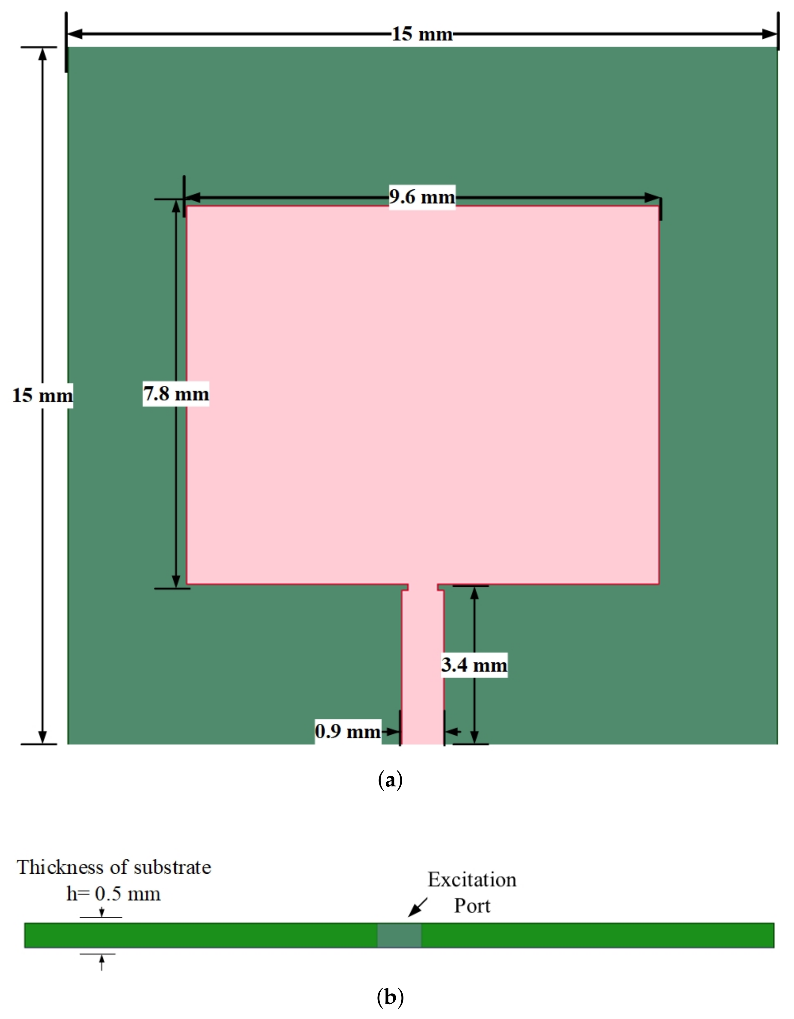
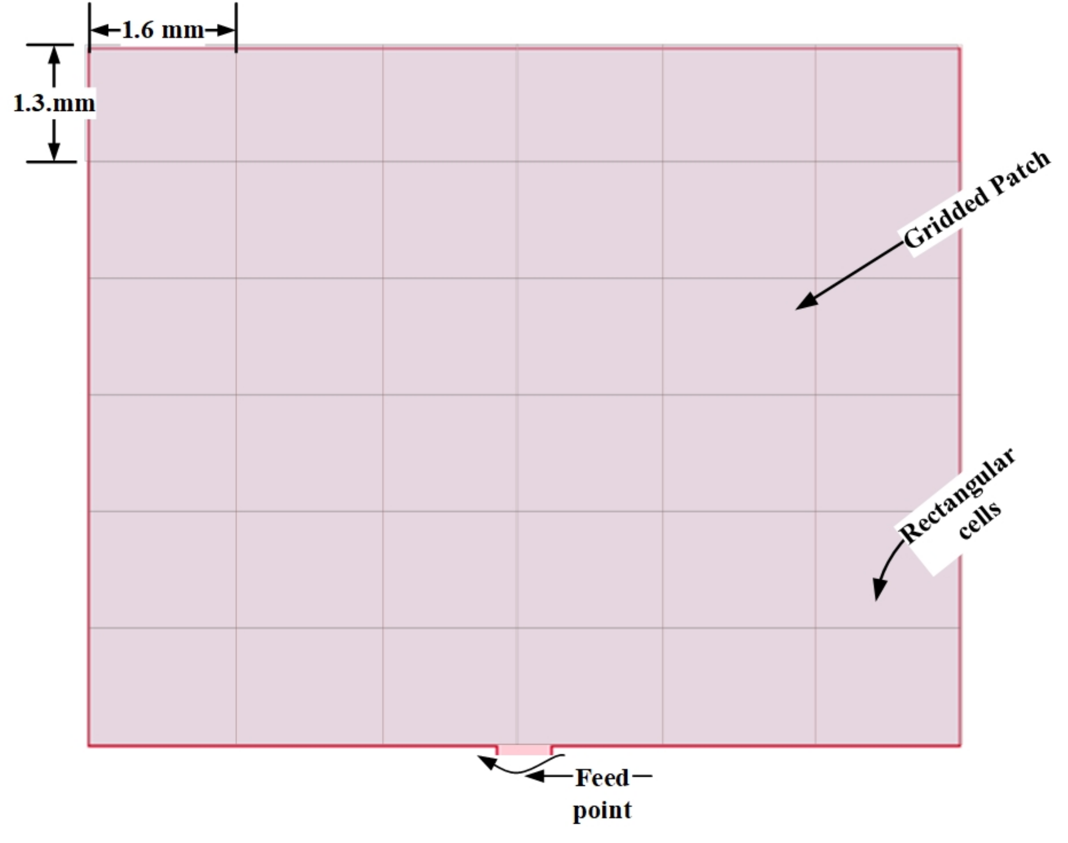
2. Antenna Modeling
3. Optimization Procedure
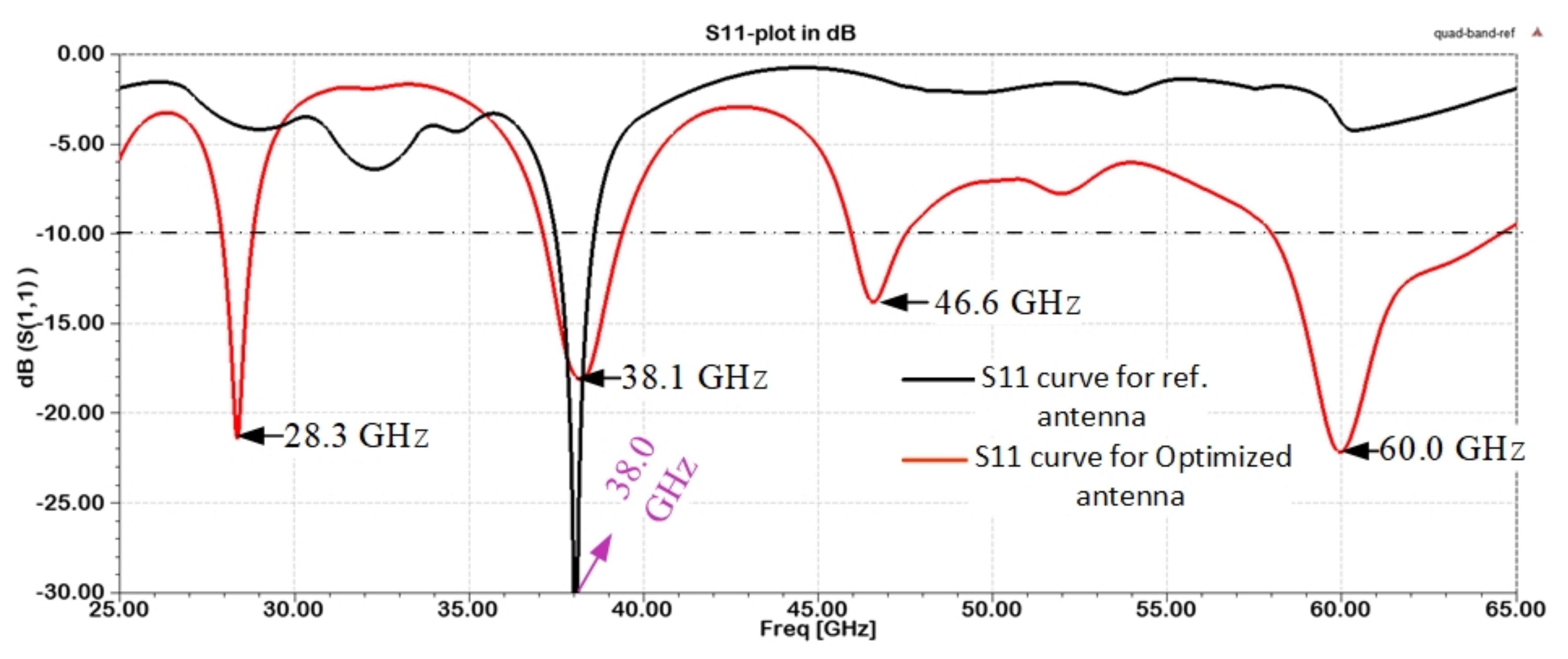
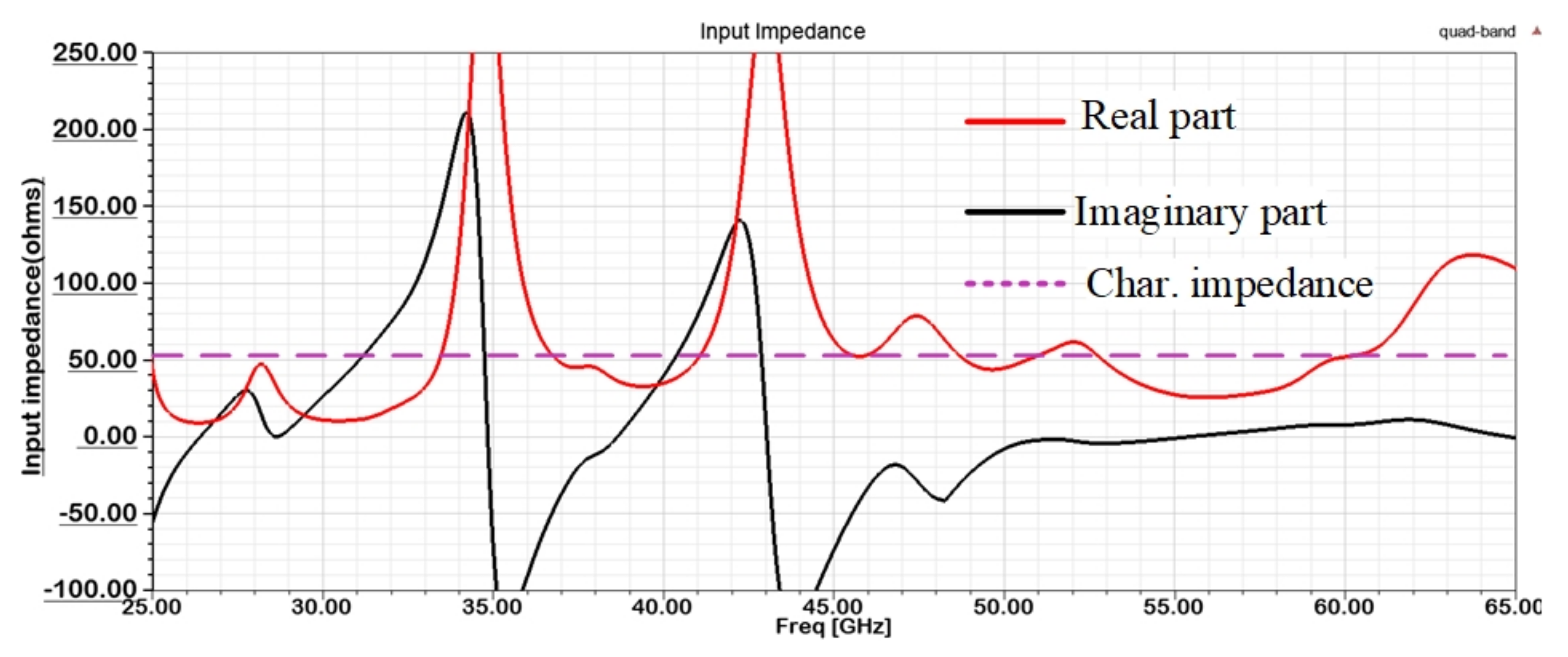
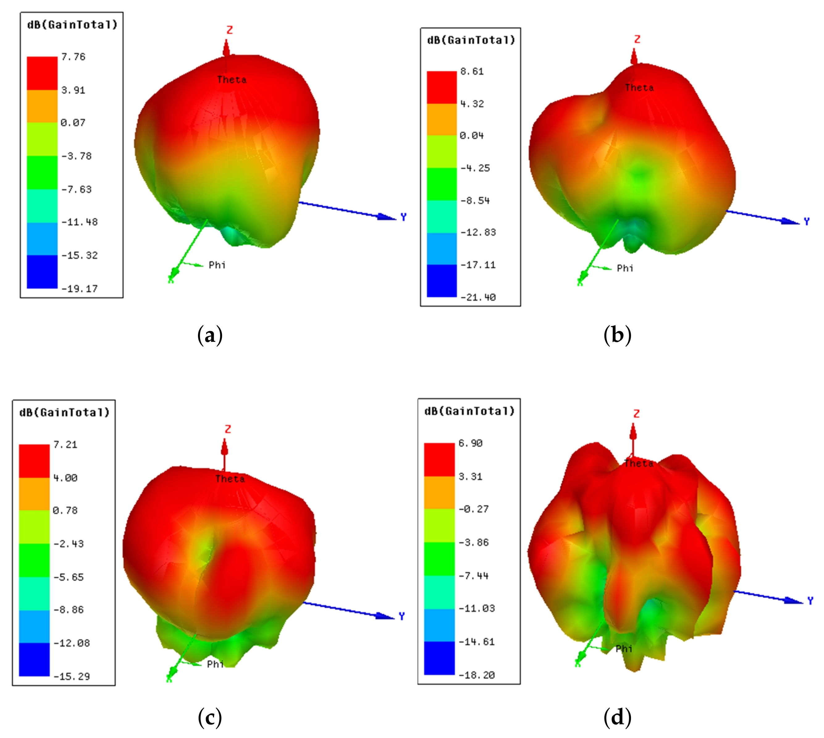
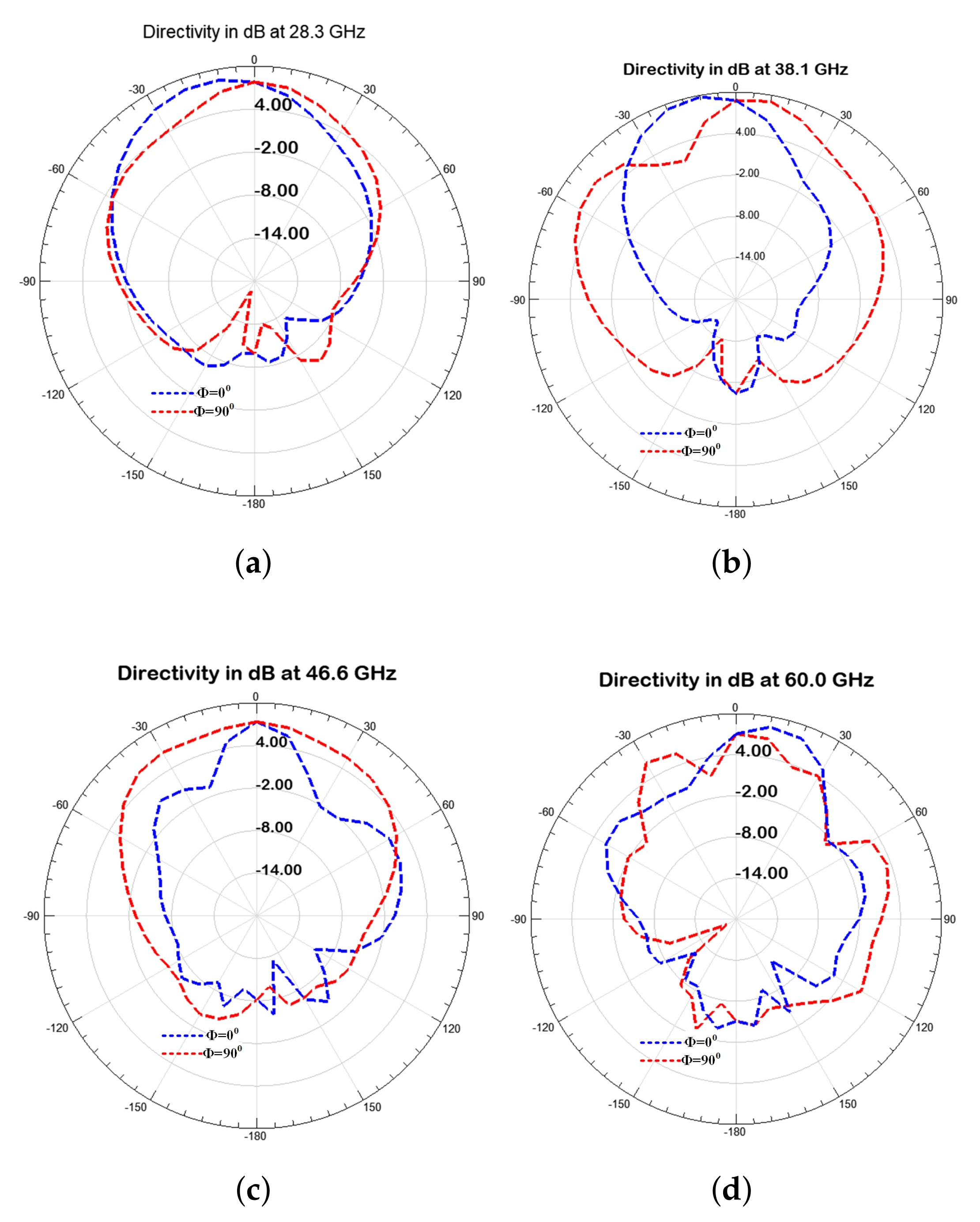
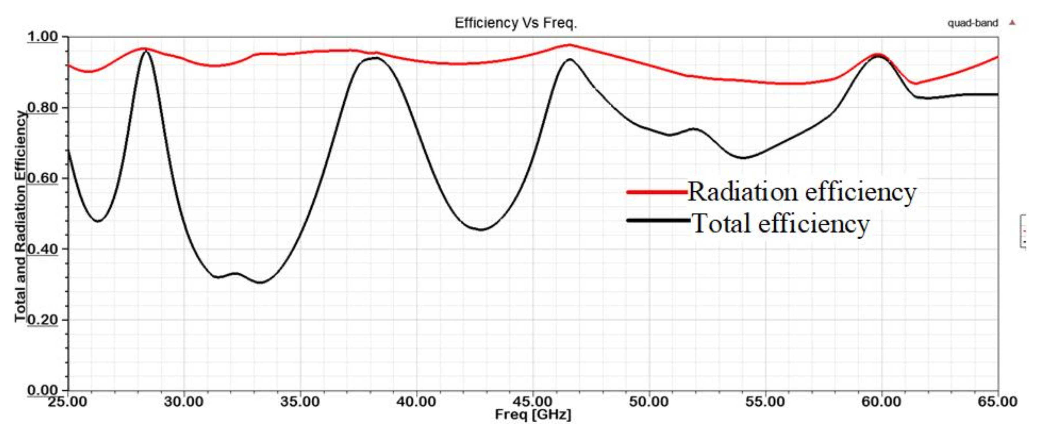
4. Results and Discussion
5. Comparison with Related Works
6. Conclusions
Author Contributions
Funding
Institutional Review Board Statement
Informed Consent Statement
Data Availability Statement
Conflicts of Interest
References
- Yeh, C.; Jo, G.D.; Ko, Y.; Chung, H.K. Perspectives on 6G wireless communications. ICT Express 2022, in press. [Google Scholar] [CrossRef]
- Xing, Y.; Rappaport, T.S.; Ghosh, A. Millimeter Wave and Sub-THz Indoor Radio Propagation Channel Measurements, Models, and Comparisons in an Office Environment. IEEE Commun. Lett. 2021, 25, 3151–3155. [Google Scholar] [CrossRef]
- Majid, M.; Habib, S.; Javed, A.R.; Rizwan, M.; Srivastava, G.; Gadekallu, T.R.; Lin, J.C.-W. Applications of Wireless Sensor Networks and Internet of Things Frameworks in the Industry Revolution 4.0: A Systematic Literature Review. Sensors 2022, 22, 2087. [Google Scholar] [CrossRef]
- Kamal, M.M.; Yang, S.; Ren, X.; Altaf, A.; Kiani, S.H.; Anjum, M.R.; Iqbal, A.; Asif, M.; Saeed, S.I. Infinity shell shaped MIMO antenna array for mm-wave 5G applications. Electronics 2022, 10, 165. [Google Scholar] [CrossRef]
- Dejen, A.; Ridwan, M.; Anguera, J.; Jayasinghe, J. Millimeter Wave Cellular Communication Performances and Challenges: A Survey. EAI Endorsed Trans. Mob. Commun. Appl. 2022, 7, e5. [Google Scholar] [CrossRef]
- Hussain, W.; Khattak, M.i.; Khattak, M.A.K. Multiband Microstrip Patch Antenna for 5G Wireless Communication. Int. J. Eng. Work. 2020, 7, 15–21. [Google Scholar] [CrossRef] [Green Version]
- Jayasinghe, J.M.J.W.; Uduwawala, D.N.; Anguera, J. Design of Dual Band Patch Antennas for Cellular Communications by Genetic Algorithm Optimization. Int. J. Eng. Technol. 2012, 1, 26–43. [Google Scholar] [CrossRef] [Green Version]
- Hu, C.; Chang, D.; Yu, C.; Hsaio, T.; Lin, D. Millimeter-Wave Microstrip Antenna Array Design and an Adaptive Algorithm for Future 5G Wireless Communication Systems. Int. J. Antennas Propag. 2016, 10, 7202143. [Google Scholar] [CrossRef] [Green Version]
- Anguera, J.; Fernández, A.; Puente, C.; Andújar, A.; Groot, J. Antenna Boosters versus Flexible Printed Circuit Antennas for IoT Devices. Signals 2022, 3, 326–340. [Google Scholar] [CrossRef]
- Simone, M.; Fanti, A.; Mazzarella, G. A Wideband Patch Antenna for 5G. In Proceedings of the IEEE International Symposium on Antennas and Propagation and North American Radio Science Meeting, Montreal, QC, Canada, 5–10 July 2020; pp. 61–62. [Google Scholar] [CrossRef]
- Lin, W.; Ziolkowski, R.W.; Baum, T.C. 28 GHz compact omnidirectional circularly polarized antenna for device-to-device communications in the future 5G systems. IEEE Trans. Antennas Propag. 2017, 65, 6904–6914. [Google Scholar] [CrossRef] [Green Version]
- Jeong, M.J.; Abbas, A.; Kim, T.J.; Kim, N. A metasurface-based low-profile wide-band circularly polarized patch antenna for 5G millimeter-wave systems. IEEE Access 2020, 8, 22127–22135. [Google Scholar]
- Zahra, H.; Hussain, M.; Naqvi, S.I.; Abbas, S.M.; Mukhopadhyay, S. A simple monopole antenna with a switchable beam for 5G millimeter-wave communication systems. Electronics 2021, 10, 2870. [Google Scholar] [CrossRef]
- Ullah, H.; Tahir, F.A. A high gain and wide-band narrow-beam antenna for 5G millimeter-wave applications. IEEE Access 2020, 8, 29430–29434. [Google Scholar] [CrossRef]
- Bilal, M.; Naqvi, S.I.; Hussain, N.; Amin, Y.; Kim, N. High-isolation MIMO antenna for 5G millimeter-wave communication systems. Electronics 2022, 11, 962. [Google Scholar] [CrossRef]
- Khalid, M.; Iffat Naqvi, S.; Hussain, N.; Rahman, M.; Mirjavadi, S.S.; Khan, M.J.; Amin, Y. 4-Port MIMO antenna with defected ground structure for 5G millimeter wave applications. Electronics 2020, 9, 71. [Google Scholar] [CrossRef] [Green Version]
- Tariq, S.; Naqvi, S.I.; Hussain, N.; Amin, Y. A metasurface-based MIMO antenna for 5G millimeter-wave applications. IEEE Access 2021, 9, 51805–51817. [Google Scholar] [CrossRef]
- Hussain, N.; Jeong, M.J.; Abbas, A.; Kim, N. Metasurface-based single-layer wide-band circularly polarized MIMO antenna for 5G millimeter-wave systems. IEEE Access 2020, 8, 130293–130304. [Google Scholar] [CrossRef]
- Dejen, A.; Jayasinghe, J.; Ridwan, M.; Anguera, J. Optimization of Dual-band Microstrip mm-Wave Antenna with Improved Directivity for Mobile Application Using Genetic Algorithm. In Proceedings of the 9th EAI International Conference on Advancements of Science and Technology, Bahirdar, Ethiopia, 27–29 August 2021. [Google Scholar]
- Buttazzoni, G.; Comisso, M.; Cuttin, A.; Fragiacomo, M.; Vescovo, R.; Gatti, R.V. Reconfigurable phased antenna array for extending cubesat operations to Ka-band: Design and feasibility. Acta Astronaut. 2017, 137, 114–121. [Google Scholar] [CrossRef] [Green Version]
- Shareef, O.A.; Sabaawi, A.M.A.; Muttair, K.S.; Mosleh, M.F.; Almashhdany, M.B. Design of multi-band millimeter wave antenna for 5G smartphones. Indones. J. Electr. Eng. Comput. Sci. 2022, 25, 382–387. [Google Scholar] [CrossRef]
- Ahmad, A.E.; Floch, J.; Lerideau, G. Quad-Band Antenna for Mobile Communication. In Proceedings of the 6th European Conference on Antennas and Propagation (EUCAP), Prague, Czech Republic, 26–30 March 2012. [Google Scholar] [CrossRef]
- Galav, K.; Meena, M.L. DESIGN AND ANALYSIS OF QUAD BAND ANTENNA FOR WIELESS SYSTEMS. Microelectron. J. 2020, 5, 866–871. [Google Scholar] [CrossRef]
- Srivastava, K.; Kumar, A.; Kanaujia, B.K.; Dwari, S.; Kumar, S. Low profile single feed monopole antenna for quad-band circularly polarised applications. Int. J. Electron. 2019, 106, 318–331. [Google Scholar] [CrossRef]
- Abdalla, M.A.; Wahba, W.W.; Atrash, M.E. A quad-band miniaturised compact ϕ-shaped CSRR-based metamaterial-inspired DG resonator antenna. Int. J. Electron. 2021, 109, 1880–1895. [Google Scholar] [CrossRef]
- Sana, M.; Ahmad, S.; Abrar, F.; Qasim, M.A. Millimeter-Wave Quad-Band Dielectric Resonator Antenna for 5G Applications. In Proceedings of the IEEE EUROCON 2021—19th International Conference on Smart Technologies, Lviv, Ukraine, 6–8 July 2021; pp. 304–307. [Google Scholar] [CrossRef]
- El-Hassan, M.A.; Farahat, A.E.; Hussein, K.F.A. Millimetric-Wave Quad-Band MIMO Antennas for Future Generations of Mobile Communications. Prog. Electromagn. Res. B 2022, 95, 41–60. [Google Scholar] [CrossRef]
- Abdelatif, N.; Zamel, H.; Attiya, A.; Awamry, A. Multi-Band mm-Wave Antenna for 5G-WiGig Communication Systems. Prog. Electromagn. Res. C 2020, 99, 133–143. [Google Scholar] [CrossRef] [Green Version]
- Almashhdany, M.B.; Al-Ani, O.A.; Sabaawi, A.M.A. Design of Multi-band Slotted mm-Wave Antenna for 5G Mobile Applications. In Proceedings of the 3rd International Conference on Sustainable Engineering Techniques (ICSET 2020), Baghdad, Iraq, 17 June 2020. [Google Scholar]
- Ding, W.; Meng, F.; Tian, Y.; Yuan, H. Antenna Optimization Based on Auto-Context Broad Learning System. Int. J. Antennas Propag. 2022, 2022, 7338164. [Google Scholar] [CrossRef]
- Zhang, X.; Tian, Y.; Zheng, X. Antenna Optimization Design Based on Deep Gaussian Process Model. Int. J. Antennas Propag. 2020, 2020, 2154928. [Google Scholar] [CrossRef]
- Kapoor, A.; Mishra, R. Genetic Algorithm Optimized Gain Augmented Dual Band Printed Antenna for Cognitive eHealth Care (IoMT) Applications. In Proceedings of the 2022 IEEE 11th International Conference on Communication Systems and Network Technologies (CSNT), Indore, India, 23–24 April 2022; pp. 6–11. [Google Scholar] [CrossRef]
- Dejen, A.; Ridwan, M.; Jayasinghe, J.; Anguera, J. Multi-Band mm-Wave Wearable Antenna Synthesized with a Genetic Algorithm. Int. J. Antennas Propag. 2022, 2022, 1958247. [Google Scholar] [CrossRef]
- Balanis, C.A. Modern Antenna Handbook; John Wiley and Sons Inc.: Hoboken, NJ, USA, 2013. [Google Scholar]
- Haupt, R.L. An Introduction to Genetic Algorithms for Electromagnetics. IEEE Antennas Propag. Mag. 1995, 37, 7–15. [Google Scholar] [CrossRef] [Green Version]
- Saraereh, O.A.; Saraira, A.A.A.; Alsafasfeh, Q.H.; Arfoa, A. Bio-Inspired Algorithms Applied on Microstrip Patch Antennas: A Review. Int. J. Commun. Antenna Propag. 2016, 6, 336–347. [Google Scholar] [CrossRef]
- Johnson, J.M.; Rahmat-Samii, Y. Genetic Algorithms in Engineering Electromagnetics. IEEE Antennas Propag. Mag. 1997, 39, 7–21. [Google Scholar] [CrossRef] [Green Version]
- Dejen, A.; Jayasinghe, J.; Ridwan, M.; Anguera, J. Genetically engineered tri-band microstrip antenna with improved directivity for mm-wave wireless application. AIMS Electron. Electr. Eng. 2022, 6, 1–15. [Google Scholar] [CrossRef]
- Jayasinghe, J.M.J.W.; Anguera, J.; Uduwawala, D.N. A simple design of multi band microstrip patch antennas robust to fabrication tolerances for GSM, UMTS, LTE, and Bluetooth applications by using genetic algorithm optimization. Prog. Electromagn. Res. M 2012, 27, 255–269. [Google Scholar] [CrossRef]


| No. | Parameter | Values |
|---|---|---|
| 1 | Population size | 30 |
| 2 | Genes in a chromosomes | 36 |
| 3 | Maximum number of generations | 100 |
| 4 | Type of Crossover | Single-point |
| 5 | Crossover Probability | 0.8 |
| 6 | Mutation | Single-bit |
| 7 | Rate of Mutation | 0.01 |
| 8 | Selection method | Tournament |
| No. | Paper | Patch Size in | Resonant freq. (GHz) | BW in GHz ( dB) | Directivity (dB) | Gain (dB) | Techniques |
|---|---|---|---|---|---|---|---|
| 1 | [6] | 0.74 × 0.79 | 28 | 0.3 | 6.7 | - | U-shaped |
| 38 | 0.5 | 7.9 | - | slot | |||
| 2 | [20] | 0.47 × 0.46 | 28 | 0.84 | 7.3 | 6.8 | Slotted |
| 38 | 0.37 | 7.5 | 7.2 | patch | |||
| 61 | 0.9 | 6.9 | 6.3 | geometry | |||
| 3 | [23] | 0.2 × 0.25 | 2.54 | 0.24 | - | Maximum | Added |
| 3.51 | 0.28 | - | gain | inverted L | |||
| 4.38 | 0.2 | - | 1.98 dB | and T | |||
| 5.3 | 0.57 | - | at 2.54 GHz | stub | |||
| 4 | [26] | 1.12 × 1.02 | 28 | Total | - | 6.9 | DRA with |
| 34 | around | - | 7.4 | slotted | |||
| 38 | 10 | - | 8.5 | ground and | |||
| 42 | GHz | - | 7.5 | superstrate | |||
| 5 | [27] | 0.93 × 1.68 | 28 | 0.6 | - | 7.3 | 4 × 4 |
| 45 | 2 | - | 7.03 | hexagonal | |||
| 51 | 1.8 | - | 7.2 | patch | |||
| 57 | 1.3 | - | 8.0 | MIMO | |||
| 6 | This work | 0.73 × 0.9 | 28.3 | 0.9 | 7.8 | 7.7 | Genetic |
| 38.1 | 2.3 | 8.8 | 8.6 | algorithm | |||
| 46.6 | 1.6 | 7.3 | 7.2 | ||||
| 60.0 | 6.7 | 7.1 | 6.9 |
Disclaimer/Publisher’s Note: The statements, opinions and data contained in all publications are solely those of the individual author(s) and contributor(s) and not of MDPI and/or the editor(s). MDPI and/or the editor(s) disclaim responsibility for any injury to people or property resulting from any ideas, methods, instructions or products referred to in the content. |
© 2023 by the authors. Licensee MDPI, Basel, Switzerland. This article is an open access article distributed under the terms and conditions of the Creative Commons Attribution (CC BY) license (https://creativecommons.org/licenses/by/4.0/).
Share and Cite
Dejen, A.; Jayasinghe, J.; Ridwan, M.; Anguera, J. Synthesis of Quadband mm-Wave Microstrip Antenna Using Genetic Algorithm for Wireless Application. Technologies 2023, 11, 14. https://doi.org/10.3390/technologies11010014
Dejen A, Jayasinghe J, Ridwan M, Anguera J. Synthesis of Quadband mm-Wave Microstrip Antenna Using Genetic Algorithm for Wireless Application. Technologies. 2023; 11(1):14. https://doi.org/10.3390/technologies11010014
Chicago/Turabian StyleDejen, Arebu, Jeevani Jayasinghe, Murad Ridwan, and Jaume Anguera. 2023. "Synthesis of Quadband mm-Wave Microstrip Antenna Using Genetic Algorithm for Wireless Application" Technologies 11, no. 1: 14. https://doi.org/10.3390/technologies11010014