Article

Improvement in Wear Resistance of Grade 37 Titanium by Microwave Plasma Oxy-Carburizing

Department of Engineering “Enzo Ferrari”, University of Modena and Reggio Emilia, 41121 Modena, Italy
*
Author to whom correspondence should be addressed.
Technologies 2023, 11(1), 13; https://doi.org/10.3390/technologies11010013
Submission received: 14 December 2022 / Revised: 3 January 2023 / Accepted: 9 January 2023 / Published: 12 January 2023
(This article belongs to the Special Issue New Advances in Microwave Technologies and Its Applications)

Abstract

:
Grade 37 titanium is widely used in racing applications thanks to its oxidation resistance up to 650 °C, but it suffers from poor wear and fretting resistance, especially at high temperature. In this paper, different surface modification techniques, namely, carburizing, coating by PVD-ZrO2 and a novel microwave plasma oxy-carburizing treatment, are investigated in terms of hardness, wear resistance and scratch hardness, compared to the untreated substrate. Numerical simulation allowed optimization of the design of the microwave plasma source, which operated at 2.45 GHz at atmospheric pressure. The proposed microwave plasma oxy-carburizing treatment is localized and can serve to improve the tribological properties of selected regions of the sample; compared to untreated Grade 37 titanium, the oxy-carburized layer presents a decrease in the wear rate at 450 °C against alumina of 54% and an increase in scratch hardness of more than three times.

1. Introduction

Pure titanium is a challenging material when it comes to tribological properties [1]. This factor limits its applications when wear and friction are involved, particularly at high temperature [2]. Two main factors have been suggested as responsible for such behavior [3], namely, low resistance to plastic shearing with low work hardening, and poor protection by the oxides which may form as a consequence of the high flash temperature induced by friction against a counterpart. Alpha-titanium alloys containing aluminum, such as Grade 37 titanium, due to its high strength-to-density ratio and high oxidation resistance up to 650 °C, are widely used in racing applications for exhaust systems. However, while presenting improved tribological properties compared to pure titanium, they show poor wear and fretting resistance [4], and this poses problems when repeated assembling and disassembling of parts is required. This results in difficulties in maintenance and inspection of the components of the exhaust system. A possible solution is surface engineering, and in particular the use of thermochemical treatments or coatings.
Surface modification techniques offer a way to improve the surface properties and corrosion resistance of titanium alloy [5]. The surface modification of materials by surface cladding technique is becoming more and more popular due to its significant progress in industrial applications [6]. Compared with other types of surface alteration methods, the cladding coating technique has the advantages of dense microstructure, high precision, low dilution rate, strong metallurgical adhesion of the cladding material with the base material, limited heat effect due to controlled energy source (laser, induction, microwaves) and rapid cooling [7,8,9,10,11].
Electrodeposition is an alternative coating method, which is rapidly gaining interest when it comes to coatings on titanium due to its appropriate features such as low cost, desirable working condition, ease of use, and suitable reproducibility, as well as the possibility of incorporating ceramic-based reinforcements, leading to metal matrix composite coatings [12,13,14]. In this framework, a possible solution to the tribological limitations of Grade 37 titanium which was recently proposed involves the use of coatings, such as the electrolytic deposition of ZrO2 coating from an aqueous solution of zirconylnitrate ZrO(NO3)2, to increase substrate resistance to environmental attacks such as corrosion, wear and high temperature oxidation [15]. Alternatively, the ZrO2 layer is deposited through PVD technique by means of Argon and pulsed arc. However, in the case of coatings, adhesion becomes an issue and the discontinuity of properties (thermal, mechanical, electrical) when passing from the substrate to the coating can represent a problem for the coating integrity, or it requires the introduction of intermediate layers.
Diffusive thermochemical treatments, on the other hand, do not show the typical abrupt variation in properties when moving from coating to the substrate, and their application can have positive effects also from the formation of new hard phases. Various surface modifications by thermochemical processes (carburizing, nitriding and oxidation) have been studied [16,17,18] and applied to practical use, improving the wear resistance of titanium alloys. These diffusion treatment techniques significantly improve wear resistance by producing a high-hardness surface layer, but they usually reduce mechanical strength, especially fatigue strength, due to brittleness introduced in the high-hardness surface layer, and disappearance of compressive residual stress, while also inducing grain growth by heating [19]. One of the best performances involves the Fresh Green process [20], which creates a carbon-doped oxide layer providing excellent durability (high hardness, high scratch resistance, wear resistance, chemical resistance, heat resistance). Alternatively, vacuum-carburizing is a well-known and effective method to introduce carbon into titanium. In this way, it is possible to create Ti-C bonds also on pre-oxidized surfaces, obtained during heat treatment. Vacuum flow (CH4-ArH2 17% vol) over substrates held at 900 °C for 21.6 ks has been used in the past to obtain high hardness (up to 1600 HV) and good wear and fretting resistance, but the main drawback is that significant grain growth occurs at that temperature. It is also possible to perform carbothermal synthesis of titanium carbide from the dioxide [21], using graphite powders deposited on titanium oxide substrate, then heating the component up to 1227 °C to form TiC.
The aim of this work was to increase the wear and fretting resistance of an alpha-titanium alloy, namely, Grade 37 titanium, for which no study exists, to the best of the authors’ knowledge, by using a one-step, relatively low-temperature, diffusive treatment. The aim was to reduce manufacturing costs and increase scratch hardness, while also preventing excessive grain growth. Such a goal was achieved by the use of microwave atmospheric plasmas. Microwave nonequilibrium plasmas at atmospheric pressure have specific characteristics; for example, the temperature of the gas can be easily controlled, reaching high values (>3000 °C). This thermal energy can be employed in materials treatment, together with active species generated in the plasma, and it has already been applied to the nitriding of titanium [22]. In this paper, a novel microwave plasma source was designed, allowing simultaneous or step-wise microwave plasma oxidation and carburizing, which was applied to Grade 37 titanium. The localized nature of the treatment allows exposing only selected regions of the sample to the oxy-carburizing, in contrast to the most commonly used thermochemical processes like vacuum carburizing.

2. Materials and Methods

2.1. Materials

Three different sets of five disk-shaped Grade 37 titanium samples, the composition of which is summarized in Table 1, having 38 mm diameter and 5 mm thickness, were superficially modified by applying an innovative microwave atmospheric plasma oxy-carburizing treatment, consisting of a first oxidizing step and a second carburizing one.
The disks were polished using SiC paper down to P2000 grit, followed by 6 μm, 3 μm and 1 μm diamond spray on soft polishing cloth, in order to start from similar surface roughness values, prior to the surface modifications.
The processed samples’ surface and tribological properties, such as hardness and wear resistance, were compared to those for other state-of-the-art treatments, like vacuum carburizing and ZrO2 coating by PVD, as described in detail in a previous work by some of the authors which will be used as reference for the comparison with the newly developed treatment [23], namely:
  • Zirconia coating: Commercially available yttria-stabilized zirconia powder (7.5Y2O3-ZrO2, Metco 6700, Oerlikon, Pfäffikon, Switzerland) was used for the plasma spray–physical vapor deposition production of coatings. Processing parameters declared by the manufacturer are: 03CP-type plasma gun; power current 2400 A; powder feed rate = 10 g/min; sample rotation 20 rpm, chamber pressure 150 Pa, deposition time = 200 s; coating thickness = 2.2 μm.
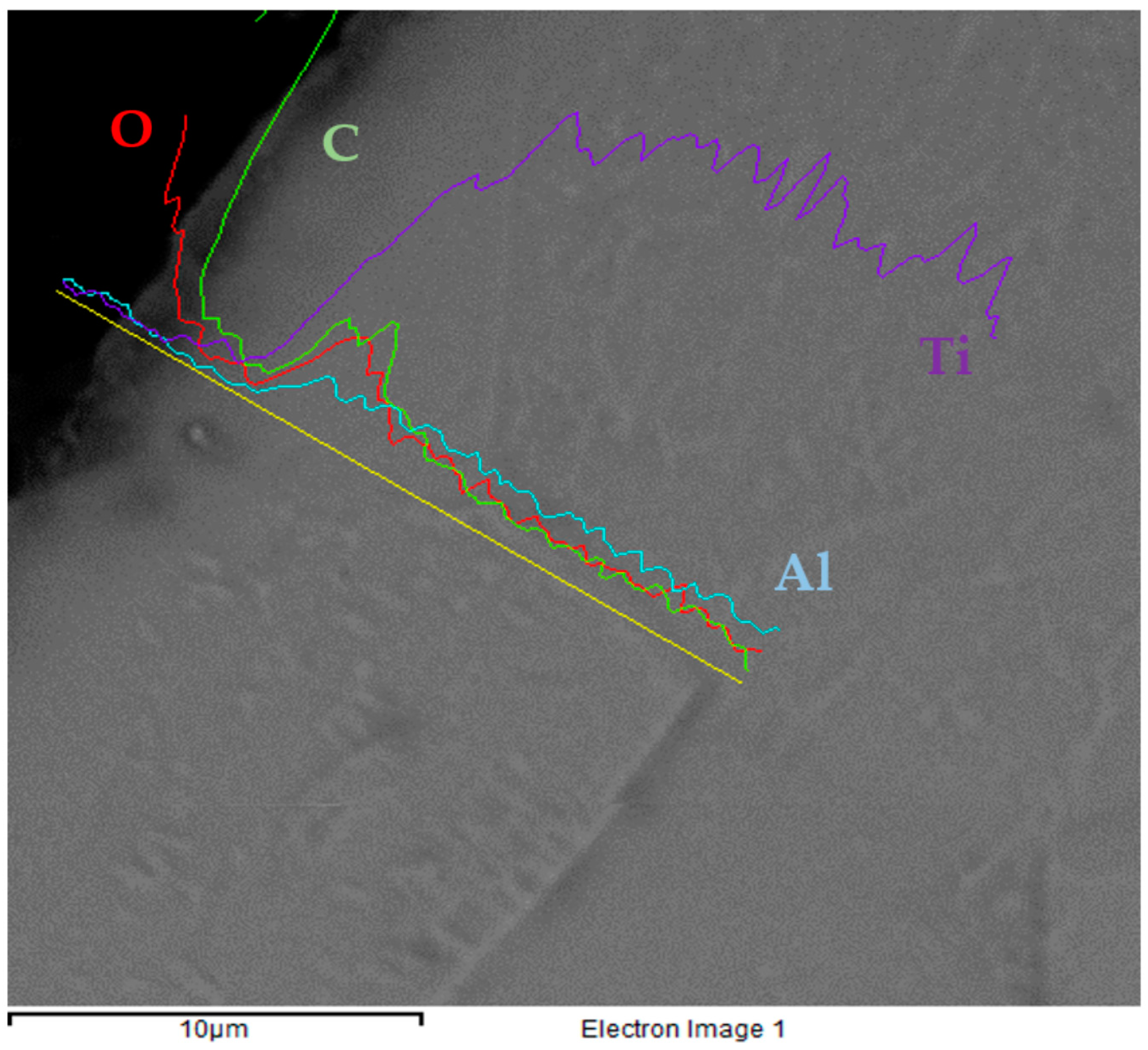
  • Carburizing: The low-pressure carburizing was conducted in an atmosphere of acethylene, ethylene and hydrogen in a ratio of 1:1:2 at 800 °C for an overall duration of 95 min. The total flow of the carburizing mixture was 0.8 L/min. The carburizing process, as declared by the supplier, was divided into two stages, namely, 40 min of carbon surface saturation and the remaining in vacuum (diffusion step). After carburizing, the samples were cooled down to below 50 °C in 300 s under nitrogen atmosphere. The modified surface thickness that resulted was on average less than 2 μm, as determined by EDS line profiles [23].
  • Microwave plasma oxy-carburizing: The optimized atmospheric plasma source described in Section 2.2 was used, with 2 kW power at 2.45 GHz, alternating feeding with commercially pure oxygen and with an industrial-grade CH4(5%)/Ar mixture. The disk-shaped sample, rotating at 50 rpm and mounted on a silicon nitride support, was exposed to the direct action of the plasma torch at a fixed distance of 50 mm from the torch outlet. The process time was 15 min, with the first 3 min in oxygen plasma and the remaining time in the CH4-Ar plasma. Additionally, in this case, the process parameters led to a similar thickness of the processed layer, approximatively less than 3.5 μm, as determined by EDS line profiles.

2.2. Microwave Plasma Treatment

Numerical simulation using the commercial software Quickwave3D (QWED, Warszawa, Poland) was used to optimize an atmospheric plasma torch which consisted of a feeding waveguide based on the WR340 geometry (cross section 86 × 43 mm), a waveguide to coaxial transition and an outer chassis for the prevention of microwave leakage and preheating of the processing gas. With reference to the names indicated in Figure 1b, the rectangular waveguide (WR340) presents two circular openings, one for the inlet (In) of gases and one opposite for the outlet of the plasma (Out). The outer part of the metal pipe connecting the input and output section is the inner conductor of a coaxial cable whose external conductor is indicated by Coax. A properly dimensioned metal Cone acts as waveguide to coaxial transition. The region where the material under processing is placed is here indicated by Treat., while the remaining part (Choke) serves only to attenuate the electromagnetic fields so that no leakage occurs. The Cone region presents an outer cavity where the gas is passed before entering the inlet section, so to act as a coolant and at the same time be pre-heated. One side of the waveguide is connected to a microwave source (magnetron), 2 kW power and operating at 2450 MHz, while the opposite side is connected to a movable short circuit (plunger) for impedance matching purposes.

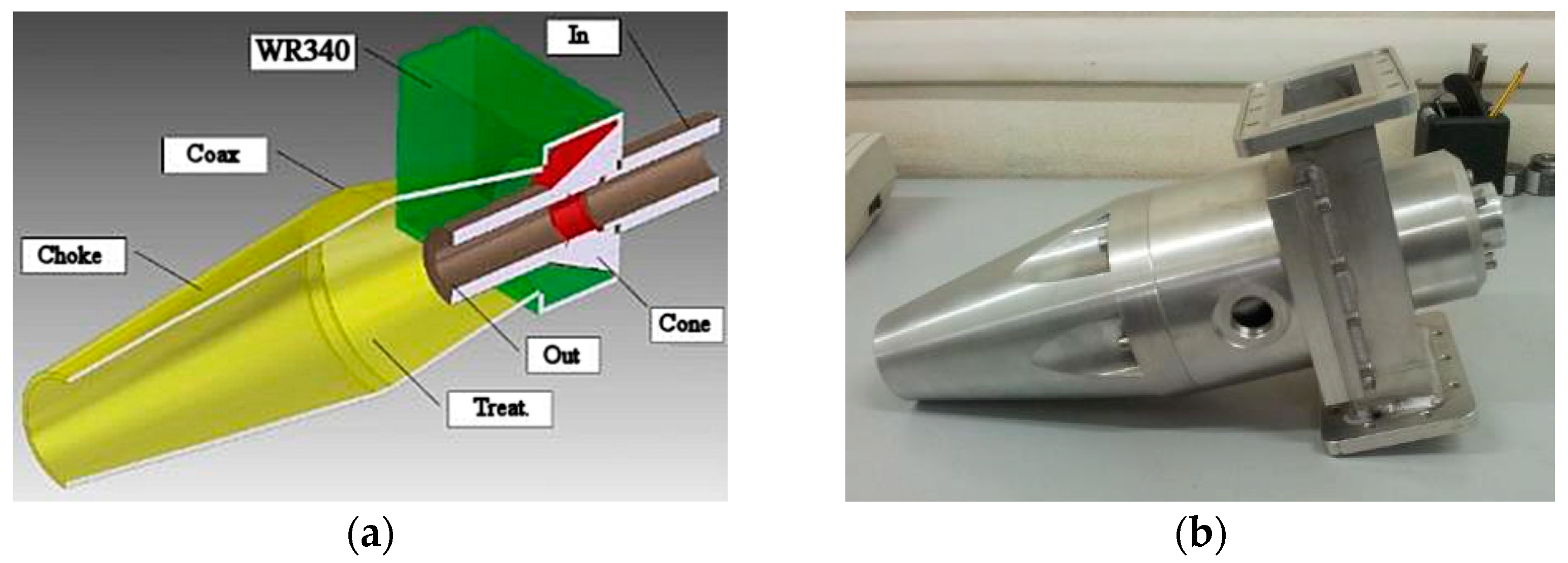
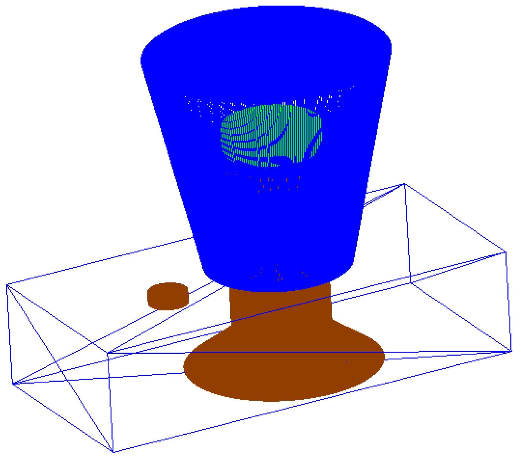
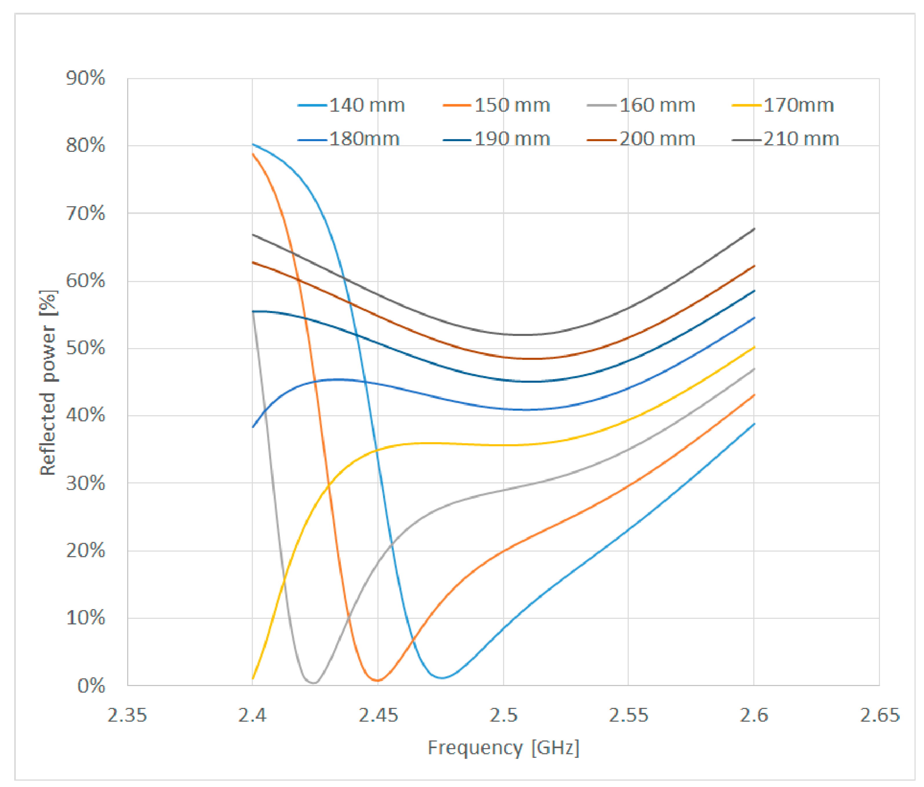
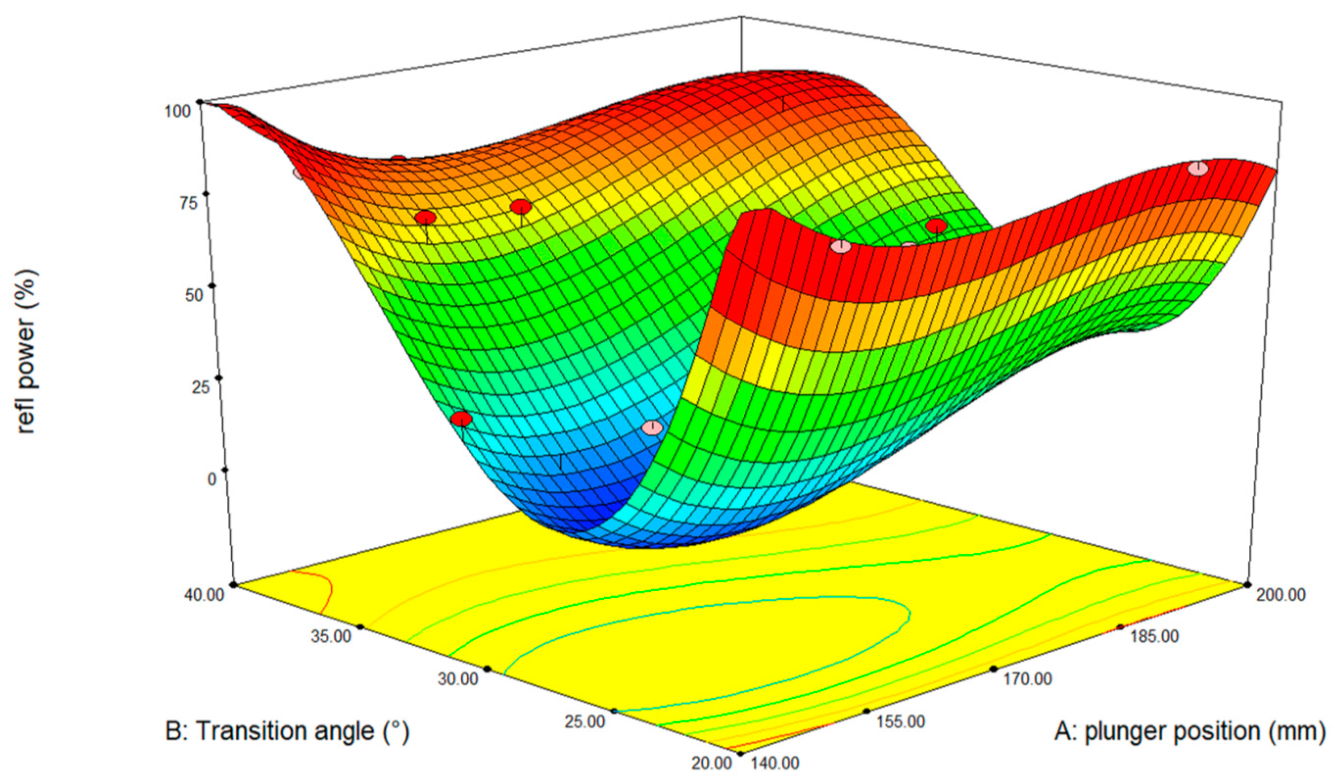
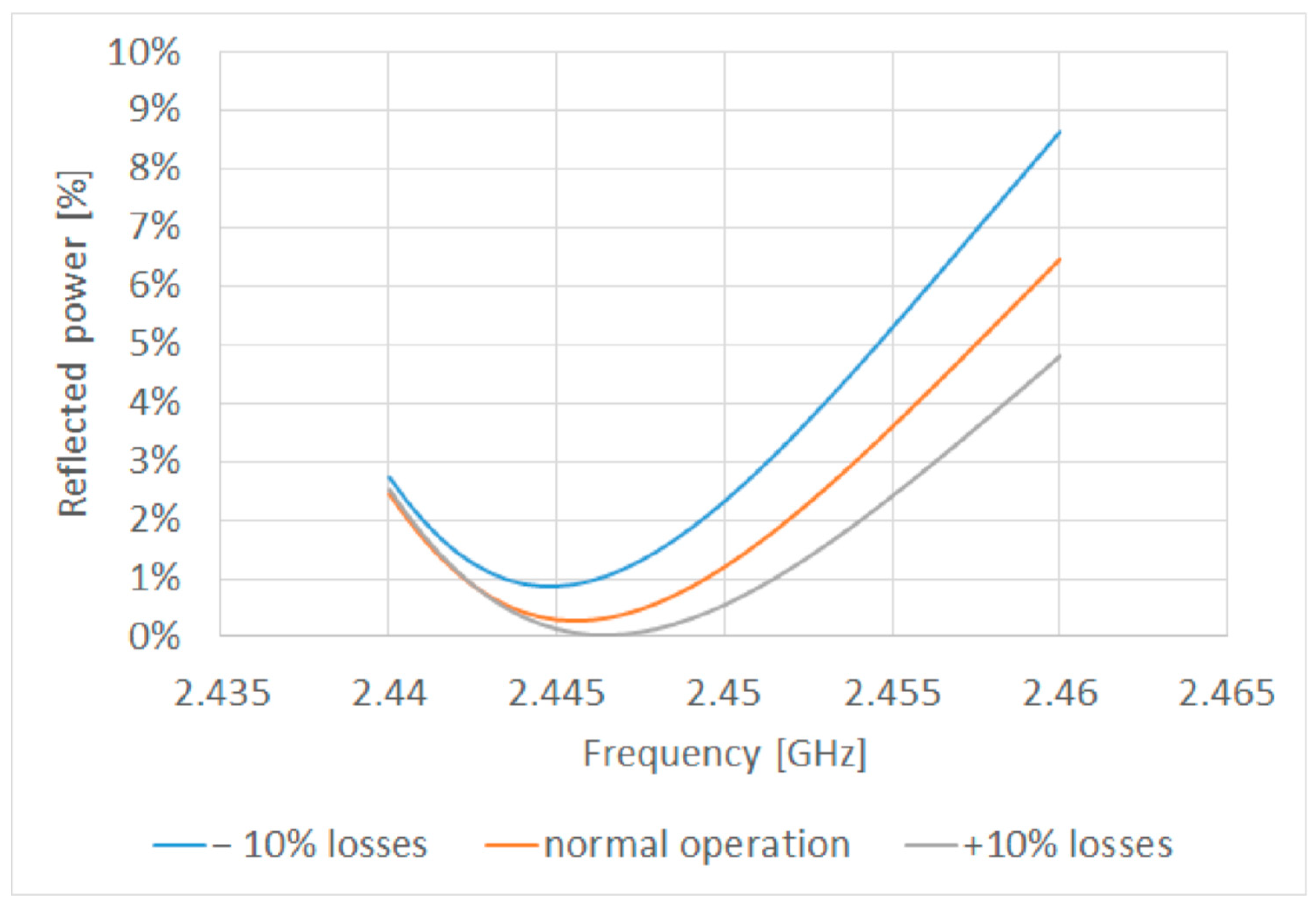
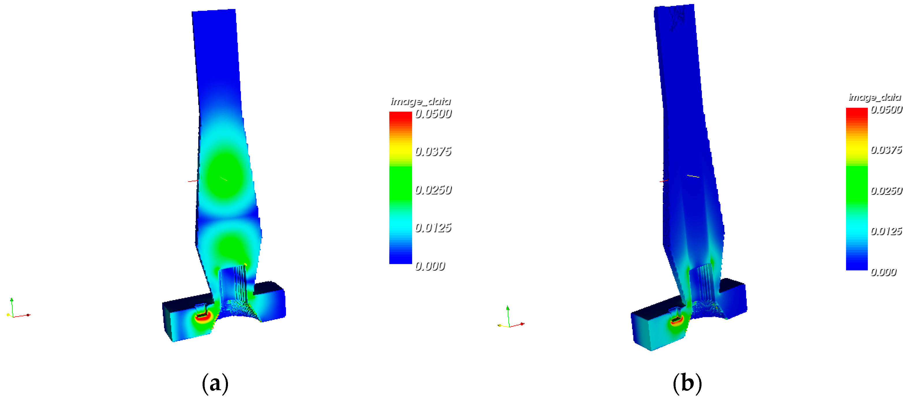
2.2.1. Optimization of the Plasma Source

Numerical simulation allowed optimization of the plasma torch design in terms of energy efficiency. The plasma torch design was based on a rectangular-to-coaxial transition of the doorknob type [24], but with the further capability to avoid any microwave leakage, while confining the atmospheric plasma to the processing region.
Plasma was simulated as an equivalent dielectric load, according to [25], and assuming a perfectly cylindrical shape having the same diameter as the ending part of the doorknob transition, to simplify the model.
Figure 2 shows the starting geometry, which includes a cylindrical metallic stub for impedance matching purposes and an upper truncated cone, representing the air volume defined by the outer metallic structure, which can be considered as a coaxial line with increasing distance between inner and outer conductors.
The preliminary optimization involved the minimization of the reflection coefficient (|S11|), at 2.45 GHz, as a function of the distance of the doorknob transition from the shorting plunger, as this was expected to have major effects on the impedance matching conditions. A reference doorknob transition dimension, with an angle of 30° of the conical section and a base radius of 34 mm, was chosen, with the upper cylindrical section (outlet pipe) having 15 mm radius.
Figure 3 shows the results, expressed in terms of the percentage of expected reflected power, which indicate the existence of a minimum in the case of a plunger length of 150 mm. Rather interestingly, the minimum was wide-banded, indicating that the microwave source, which in the case of a magnetron has a broad spectrum as well, is likely to be well matched also at a slightly different frequency than the expected 2.45 GHz, but still within the allowed ISM band.
However, the relevant shape and dimensions of the doorknob transition was expected to have complex effects on the distribution of the electromagnetic field, so a virtual design of experiment approach [26] was used to find possible interactions between the design factors, namely the plunger position and the doorknob shape, the latter expressed in terms of the angle of the metal cone. Assuming as a constraint that the top of the truncated cone must be ending with a top section of 15 mm radius at 34 mm height from the bottom of the waveguide, to ease connection to the upper gas outlet pipe, such an angular parameter completely describes the transition geometry.
A predictive model of the design parameters was developed using the response surface method and it is graphically illustrated in Figure 4.
The predicted R-square value of the obtained data was 0.937 and both two-factor interactions and quadratic effects were considered. Moreover, from the plot of Figure 4, it is also evident that the plunger position was affecting the expected energy efficiency less than the angle of the cone in the considered intervals of the investigated variables.
Figure 4 shows also that, in case of a poorly designed transition, no plunger position alone is able to compensate it. Based on such results, an optimized version of the torch was modelled using the minimum of the response surface and resulting in reflections lower than 1%, as shown, limited to the ISM band, in Figure 5. Figure 5 shows also the effects of possible variations in the plasma parameters of plus/minus 10% during normal operation.
These effects were not as relevant as the transition dimensions, but they did require compensation; hence, a movable metallic stub was introduced into the model, as previously shown in Figure 2. Last but not least, it needed to be considered that the proposed geometry of the plasma torch did not prevent microwave leakage from the top of the cone; hence, a further conical feature was introduced, so to act as a cylindrical waveguide under cut-off conditions.
Figure 6 shows, in vertical cross sections of the plasma torch, that no emission occurred, neither in the case of pre-ignition of the plasma (Figure 6a) nor after its ignition (Figure 6b).

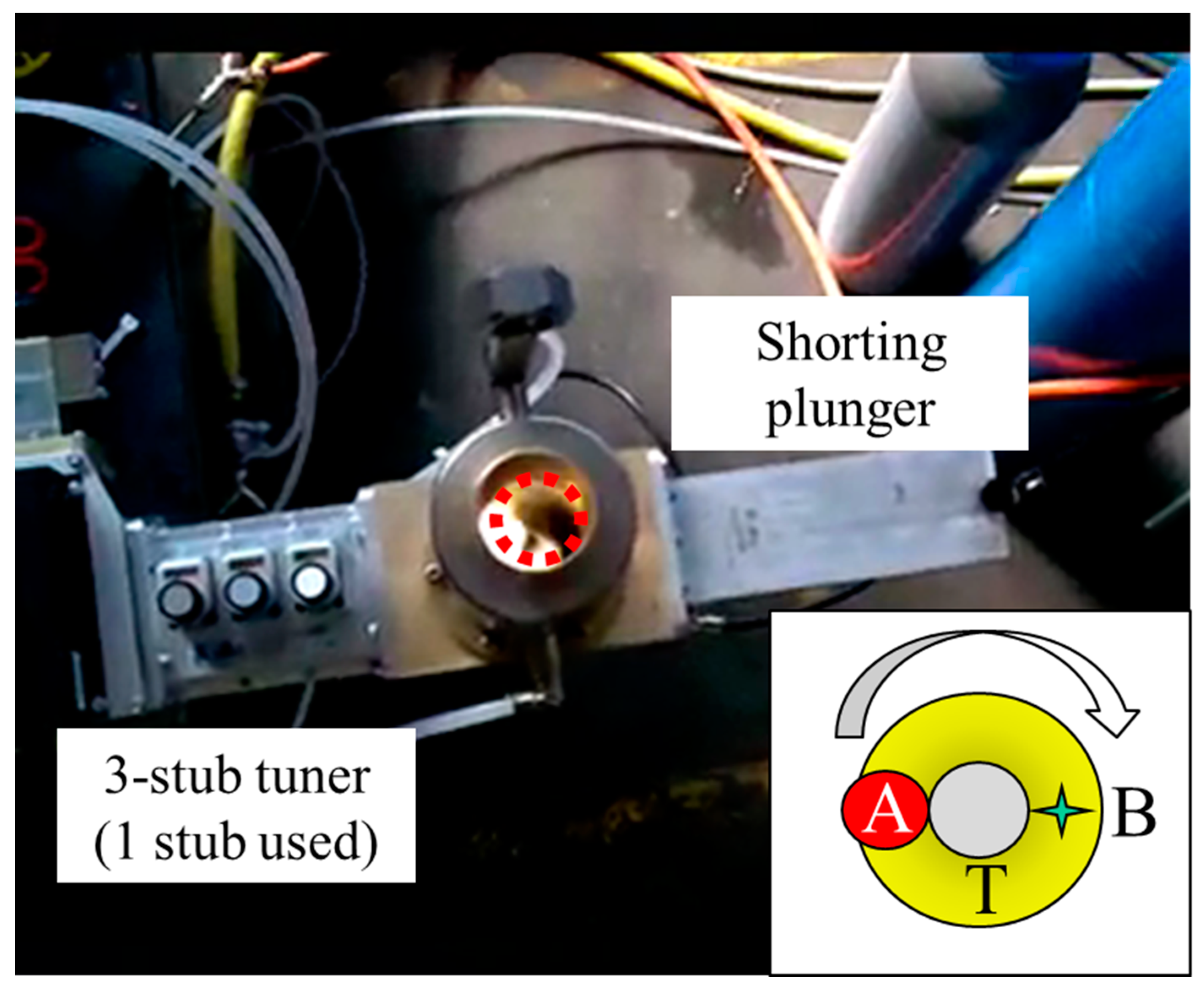
2.2.2. Operation of the Plasma Source

The plasma torch was operated connected to an MKS Alter magnetron generator GS020 operating at 2.45 GHz, with the insertion of a three-port circulator to continuously monitor reflected power on the third port by means of a RD8400 Linear Power Sensor—MKS Instruments, Reggio Emilia, Italy. Measurements, with the reference being Ar plasma, demonstrated that practically no reflections occurred once the metallic stub had been properly regulated. Measurements of the reflected power, by means of a power sensor, indicated reflections lower than 5% before plasma ignition, then going down to less than 1% after plasma ignition and impedance matching by the movable stub, in agreement with the simulated results.
For the improvement of the surface properties of the Grade 37 titanium by oxy-carburizing, the plasma torch was operated varying the gases, in particular using alternate feeding with commercially pure oxygen and with an industrial-grade CH4(5%)/Ar mixture. The latter gas mixture is known from the literature to promote microwave plasma carburizing of steels [27]. However, for simplicity’s sake, and to simulate the possible treatment of irregularly shaped surfaces, the plasma torch treatment was performed at atmospheric pressure, exposing the disk-shaped sample to the direct action of the plasma torch at a fixed distance of 50 mm from the torch outlet. The disk-shaped sample was mounted on a rotating support, at 50 rpm, with the center of rotation off-centered with respect to the plasma torch. Under these conditions, a ring-shaped plasma-treated track was generated. An optical pyrometer (IKS-T14-09, Sitel control Srl, Milan, Italy), positioned symmetrically with respect to the plasma torch, was used to monitor the surface temperature of the sample immediately after it exited from the plasma processing region. An overall processing time of 15 min was applied, with the first 3 min in oxygen plasma and the remaining in the CH4-Ar plasma.
The overhead view in Figure 7 depicts the experimental setup used, indicating with A the region of the sample directly exposed to the plasma torch, with B the pyrometer measurement point and with T the oxy-carburized track which was created as a consequence of sample rotation. The dotted circle in the main picture of Figure 7 indicates the position of the sample during processing.

2.3. Samples Characterization

Samples characterization, involving a minimum of three different samples for each tested condition and in agreement with previous work, consisted of:
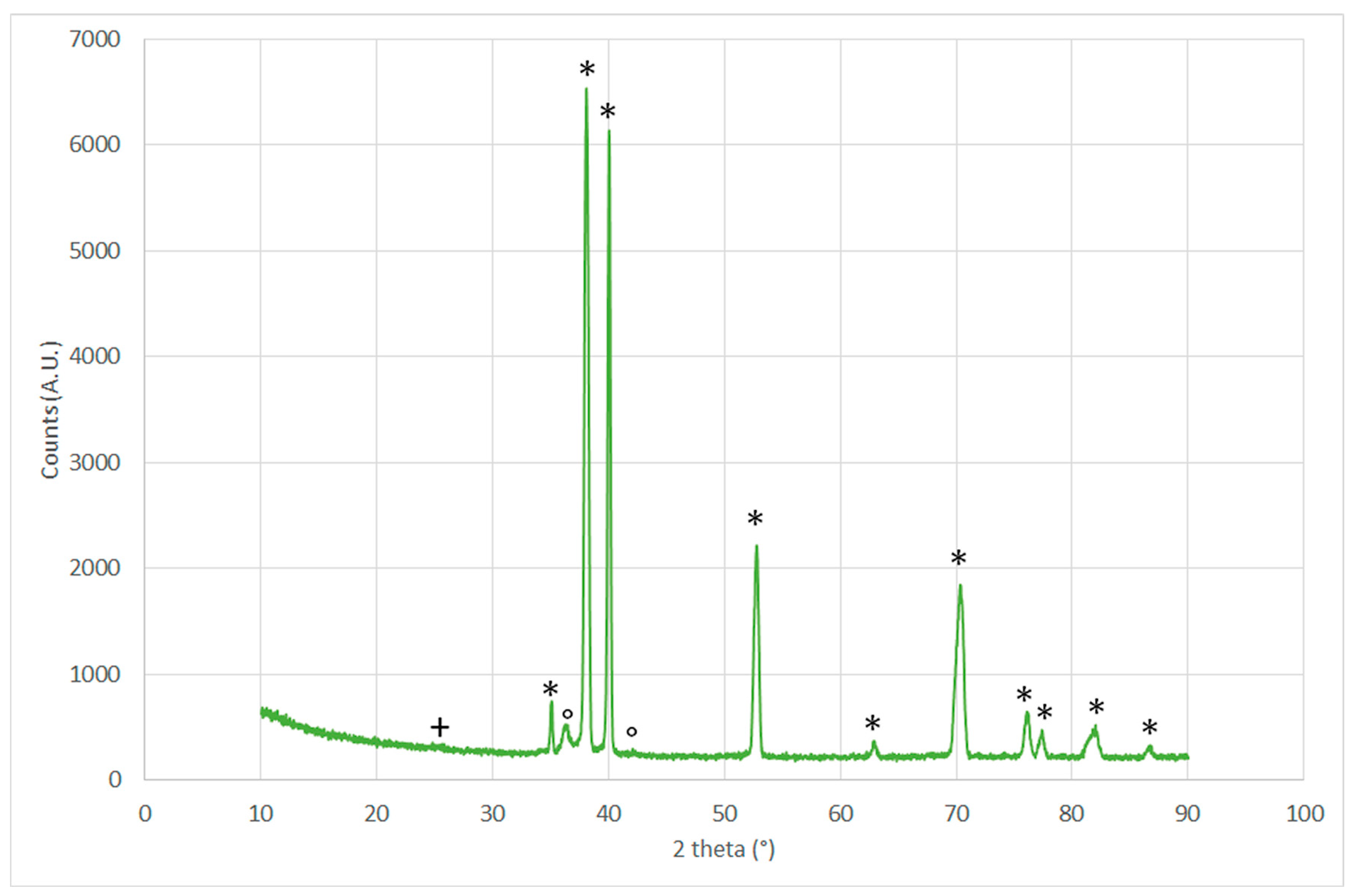
  • X-ray diffraction (XRD) for phase identification: A Θ/2Θ scan was performed in the 2Θ range from 20° to 90° using a Panalytical X’Pert PRO diffractometer equipped with a gas proportional detector. A parallel beam configuration was applied, including an X-ray mirror (incident beam optics) coupled with a long soller slit and a flat monochromator (diffracted beam optics). An X-ray tube with a copper anode and Ni filter on the detector was used.
  • SEM/EDS: An ESEM PHILIPS XL30 was used in conjunction with energy dispersive spectroscopy, EDS FEI COMPANY ESEM QUANTA 200, for microstructural investigation of the cross sections.
  • Roughness: Measurements were made by stylus surface roughness tester, SAMA TOOLS, model SA6220 (five measurements, with 30 mm length, were performed circumferentially for each sample).
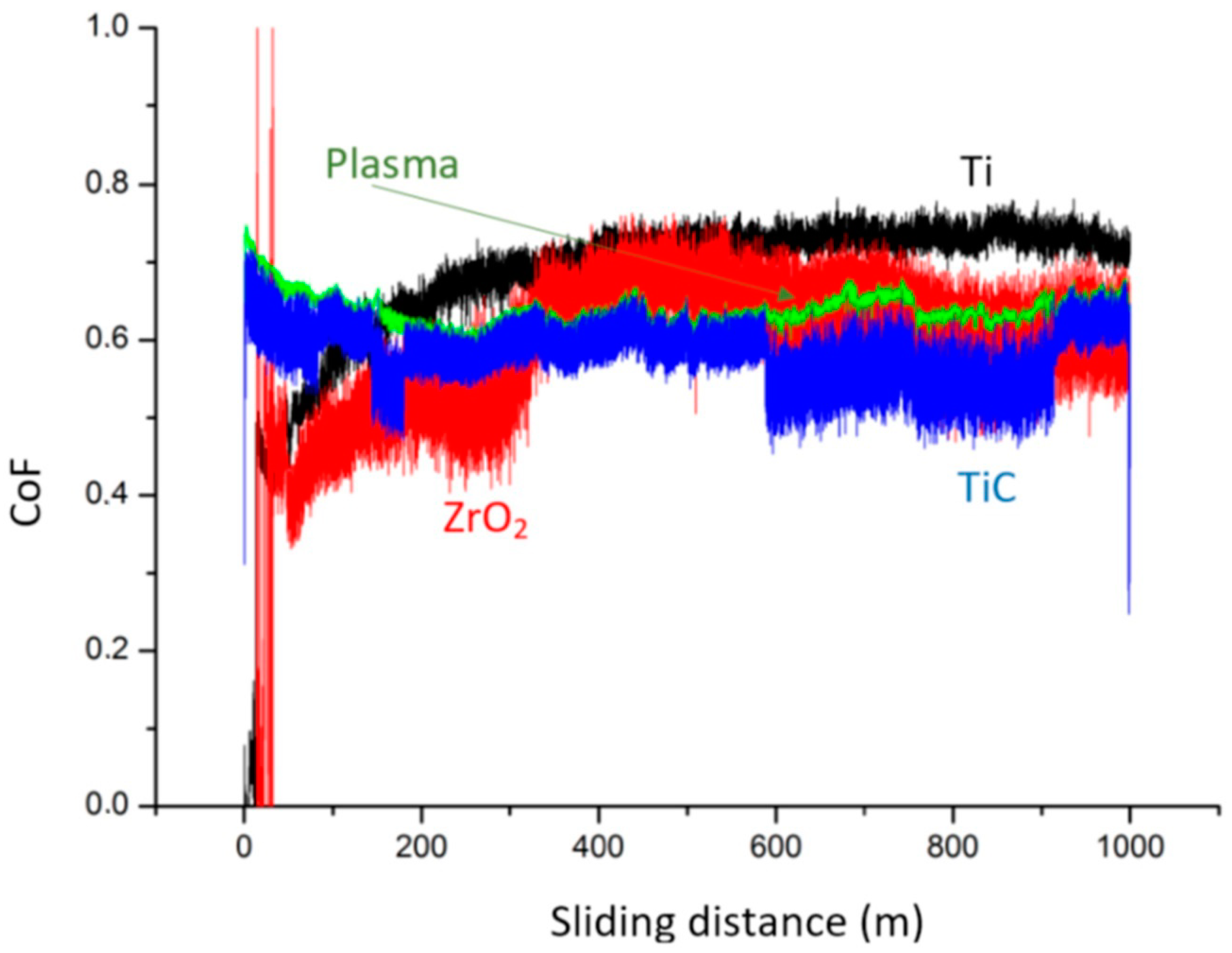
  • Tribology test: A pin-on-disk, CSM Instrument, was used for measuring wear rate and friction coefficient against alumina (3 mm diameter pin, normal load = 5 N; sliding speed = 200 mm/s, sliding distance 1000 m, radius = 8 mm) as a function of sliding distance at 450 °C. Wear rate was calculated by measuring the worn surface profile with a CSM Conscan profilometer at three different locations, and averaging the values of the worn areas to reconstruct the removed volume, taking into account the 8 mm radius applied during tests (software CSM ImagePlus 2.9). This set of parameters was used in order to achieve a direct comparison with the results for other protective coatings on titanium developed by some of the authors [9,11,23] and it was selected because such conditions of slow sliding speed and load are known from the literature to present higher wear rates in dry sliding between titanium and alumina [28].
  • Hardness: Nanoindentation testing using a CSM Micro Combi Tester with a Berkovich indenter, using a 200 mN load (surface) or 50 mN load (cross section), and load holding time of 10 s; the values were then converted into Vickers Hardness Numbers using the built-in control software for the sake of comparison.
  • Scratch hardness: This was measured by CSM Micro Combi Tester, following ASTM G 171-03, with 3 scratches, using a 0.2 mm diameter Rockwell indenter, applying 3 N normal load for a sliding distance of 5 mm.

3. Results

3.1. X-ray Diffraction

X-ray diffraction, as shown in Figure 8, evidenced that the plasma-treated samples present the typical peaks of titanium oxide and carbide, as expected, but the signal ascribable to the rutile was only slightly above the background, while the peaks ascribed to TiC could also indicate the formation of Ti(C,N).
This can be a result of the processing conditions, with the rotating sample surface periodically exposed to air and hence not protected from contact with nitrogen.

3.2. Microstructure

Polished and etched cross sections were prepared in order to investigate the element distribution in the plasma-treated samples, using scanning electron microscopy, to qualitatively assess the existence of an oxygen- and carbon-richer layer on the surface. Figure 9 shows the relevant elements distribution along a scanning line perpendicular to the surface in the cross section of the sample.
Results demonstrated that the plasma treatment was effective in enriching the surface layers with carbon and oxygen, even if to only a very limited extent, and it was quantifiable at almost 2.7 μm. A further peak of oxygen and carbon concentration was encountered at a slightly deeper distance from the surface (7.3 μm), probably due to the presence of a grain boundary crossing the measurement line. The higher diffusion coefficient at a grain boundary can explain this apparently anomalous behavior, but also suggests the possibility of improving diffusion when it is applied on starting materials with smaller grain size.

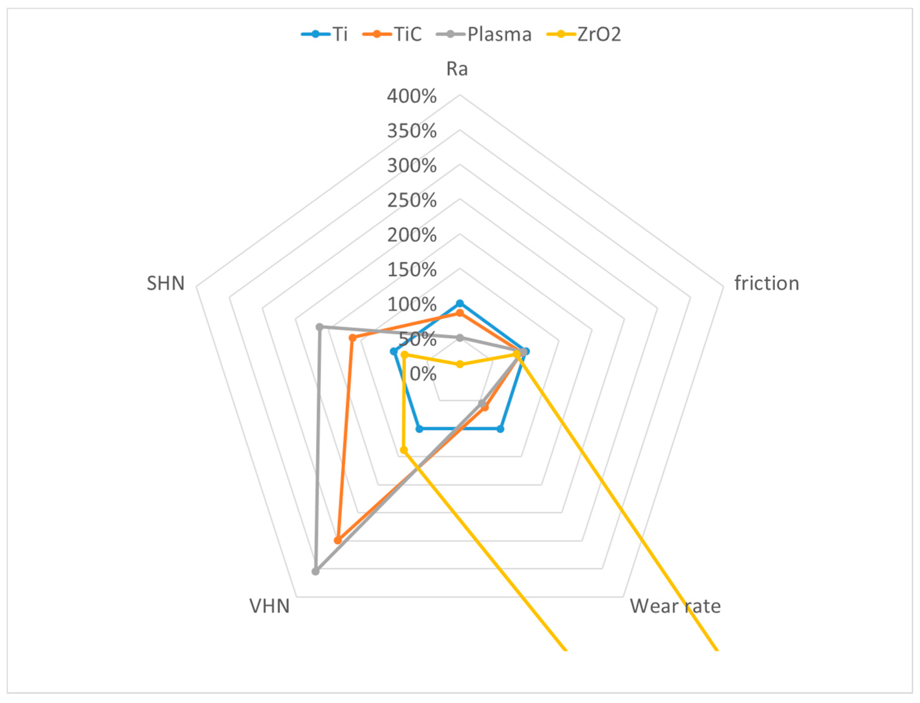
3.3. Surface and Tribological Properties

The measured surface and tribological properties are summarized in Table 2 and are depicted for the sake of comparison in Figure 10, where Grade 37 titanium properties are expressed as 100% values.
Results demonstrated that the newly developed plasma treatment provides properties comparable to the ones of the conventionally carburized parts, with slightly better behavior during wear tests. The literature results used for comparison showed also poor behavior for the zirconia-coated sample with respect to wear rate, but this is explained by the poor adhesion of such coatings, as measured by scratch test. Of course, this problem is not encountered in the case of diffusive treatments, like carburizing or oxy-carburizing. However, diffusive treatments, and the newly developed one in particular, presented a higher scattering of results, as indicated by the deviations in Table 2. This was expected in the case of the microwave plasma oxy-carburized sample, because the formation of the treated track was achieved by non-coaxial rotation with respect to the plasma source, and this introduced possible radial variations in the intensity of the treatment, in particular temperature.
Friction coefficient in dry sliding against alumina was similar for both diffusive treatments, and this was a further indication of the possible similarity of the chemical composition and microstructure existing at the surface. However, it should be noticed that the results plotted in Figure 10 refer only to the average coefficient of friction measured from 50 to 1000 m of sliding, while a more complex behavior can be observed by analyzing the CoF as a function of the sliding distance, as shown in Figure 11.
After an initial running in phase, the untreated surface presented an increasing CoF, which resulted in a maximum after 1000 m sliding. A similar trend was observed in the case of the zirconia coating, with a discontinuity after 330 m sliding, which corresponds to the almost complete removal of the coating from the wear track. This is in agreement with the adhesion of this coating to the titanium substrate, as measured by scratch testing [23]. The two diffusive treatments, on the other hand, did not present such a trend, maintaining an almost constant CoF. Among the two, the curve referring to the carburized sample results was much less regular, and the observation of debris on the worn track evidenced the presence of titanium carbides, which is not as relevant in case of the oxy-carburized samples. The different thicknesses of the diffusive layers, as well as the presence of different residual stresses, can be also responsible for the different tribological behaviors observed. As a matter of fact, the carburized sample was rapidly quenched in nitrogen after the diffusive treatment, while the oxy-carburized one was subjected to cyclic heating and cooling, but at the end of the process it was naturally cooled with a moderate Ar flux. Moreover, the carburized sample was completely inserted in the processing furnace, while the plasma-treated one was only locally treated and rotated on its axis. This is expected to generate a peculiar distribution of stress along the radial direction as well, which will be the subject of future investigation. Based on these premises, the residual stresses existing in the investigated samples were different, and this was reflected also in a different tribological behavior. It is worth noticing that, during the tribological tests at 450 °C, a moderate stress relief can occur according to the literature data [29] which, for a similar temperature (480 °C) and duration (83 min), forecast a halving of the initial residual stresses.
In this framework, the superior performance of the oxy-carburized samples can be ascribed mainly to the higher penetration depth achieved compared to the commercial carburizing process applied, and possibly to the existing residual stresses. However, by changing the oxy-carburizing duration and intensity, a further growth of the treated layer is expected, and a more obvious formation of the titanium oxides should occur, as has already been observed in the aforementioned “Fresh Green” process. Last but not least, a further improvement could also be reached by implementing radial movement of the sample, to improve treatment homogeneity, as well as by adding a further step to modify the existing residual stresses, preferably by shot peening.

4. Conclusions

A compact microwave plasma torch operating at 2.45 GHz was designed and optimized by means of numerical simulation. The waveguide to coaxial transition geometry, which is of the doorknob type, is the main parameter affecting the energy efficiency of the torch, and it was optimized in order to be able to also withstand small variations in the plasma parameters during normal operation. The plasma torch was built and tested to perform oxy-carburizing treatments on Grade 37 titanium, with the aim to increase its wear and scratch resistance at high temperatures. Compared with the data in the literature for state-of-the-art surface modifications of such alloys, such as carburizing and PVD coating with zirconia, the newly developed plasma-assisted oxy-carburizing process provides excellent tribological properties, similar or superior to vacuum-carburized samples. An overall reduction of 54% in the wear rate in dry sliding against alumina at 450 °C was achieved, as compared to untreated Grade 37 titanium, with an almost three times higher surface hardness. This was reflected also in the scratch hardness measurements, making the newly developed process suitable for the surface treatment of exhaust pipes and connectors. Further development of the technique includes the possibility of moving the plasma source with a robotic arm, so that the processing of complex shape parts can be implemented as well.

Author Contributions

Conceptualization, P.V. and A.B.; methodology, E.C. and A.B.; software, E.C. and P.V.; validation, A.B. and E.C.; formal analysis, P.V.; investigation, E.C.; resources, P.V.; data curation, P.V.; writing—original draft preparation, A.B. and E.C.; writing—review and editing, P.V.; visualization, P.V.; supervision, P.V.; project administration, E.C. and P.V.; funding acquisition, P.V. All authors have read and agreed to the published version of the manuscript.

Funding

This research received no external funding but used resources originally developed within the framework of the Italian project n. F/170005/00/X42.

Institutional Review Board Statement

Not applicable.

Informed Consent Statement

Not applicable.

Acknowledgments

Metallurgica Abruzzese SpA (Italy) is kindly acknowledged for realizing the plasma torch prototype and having the authors use it for its preliminary testing. The plasma torch was designed within a larger framework dedicated to metal surface treatment, Project n. F/170005/00/X42 «Realizzazione di nuovo filo metallico sostenibile e batteriostatico non plastificato, per la produzione di gabbie galleggianti offshore e inshore per maricoltura di specie autoctone e alloctone sia in acque calde che fredde» of the Italian Ministry of Economic Development.

Conflicts of Interest

The authors declare no conflict of interest.

References

  1. Budinski, K.G. Tribological properties of titanium alloys. Wear 1991, 151, 203–217. [Google Scholar] [CrossRef]
  2. Alam, M.O.; Haseeb, A.S.M.A. Response of Ti–6Al–4V and Ti–24Al–11Nb alloys to dry sliding wear against hardened steel. Tribol. Int. 2002, 35, 357–362. [Google Scholar] [CrossRef]
  3. Molinari, A.; Straffelini, G.; Tesi, B.; Bacci, T. Dry sliding wear mechanisms of Ti6Al4V alloy. Wear 1997, 208, 105–112. [Google Scholar] [CrossRef]
  4. Lütjering, G.; Williams, J.C. High temperature alloys. In Titanium. Engineering Materials, Processes, 2nd ed.; Springer: Berlin/Heidelberg, Germany, 2007; pp. 259–282. [Google Scholar] [CrossRef]
  5. Bloyce, C.A.; Qi, P.Y.; Dong, H.; Bell, T. Surface modification of titanium alloys for combined improvements in corrosion and wear resistance. Surf. Coat. Technol. 1998, 107, 125–132. [Google Scholar] [CrossRef]
  6. Obadele, B.A.; Andrews, A.; Mathew, M.T.; Olubambi, P.A.; Pityana, S. Improving the tribocorrosion resistance of Ti6Al4V surface by laser surface cladding with TiNiZrO 2 composite coating. Appl. Surf. Sci. 2015, 345, 99–108. [Google Scholar] [CrossRef]
  7. Weng, F.; Chen, C.; Yu, H. Research status of laser cladding on titanium and its alloys: A review. Mater. Des. 2014, 58, 412–425. [Google Scholar] [CrossRef]
  8. Adesina, O.S.; Obadele, B.A.; Farotade, G.A.; Isadare, D.A.; Adediran, A.A.; Ikubanni, P.P. Influence of phase composition and microstructure on corrosion behavior of laser based Ti–Co–Ni ternary coatings on Ti–6Al–4V alloy. J. Alloy. Compd. 2020, 827, 154245. [Google Scholar] [CrossRef]
  9. Veronesi, P.; Rosa, R.; Poli, G.; Casagrande, A.; Cammarota, G.P. Tough and wear resistant Ni-Al based thick intermetallic coatings on titanium Obtained by microwave assisted SHS. In Proceedings of the Euro International Powder Metallurgy Congress and Exhibition, Euro PM 2008, Mannheim, Germany, 29 September–1 October 2008; Volume 3, pp. 71–76. [Google Scholar]
  10. Veronesi, P.; Rosa, R.; Poli, G.; Casagrande, A.; Boromei, I. Effect of Si and Cr content on the high temperature oxidation resistance of aluminide coatings on Ti obtained by microwave assisted SHS of metallic powders mixture. In Proceedings of the World Powder Metallurgy Congress and Exhibition, World PM 2010, Florence, Italy, 10–14 October 2010; Volume 5, pp. 1–6. [Google Scholar]
  11. Boromei, I.; Casagrande, A.; Poli, G.; Veronesi, P.; Rosa, R. Oxidation behavior resistance of a duplex NiAl/Ti-Ni-Al coating by microwave assisted SHS on Ti substrate. In Proceedings of the Euro PM2009, Copenhagen, Denmark, 12–14 October 2009; pp. 161–166. [Google Scholar]
  12. Rasooli, A.; Safavi, M.S.; Ahmadiyeh, S.; Jalali, A. Evaluation of TiO2 Nanoparticles Concentration and Applied Current Density Role in Determination of Microstructural, Mechanical, and Corrosion Properties of Ni–Co Alloy Coatings. Prot. Met. Phys. Chem. Surf. 2020, 56, 320–327. [Google Scholar] [CrossRef]
  13. Rosa, R.; Veronesi, P.; Michelazzi, M.; Leonelli, C.; Boccaccini, A.R. Combination of electrophoretic deposition and microwave-ignited combustion synthesis for the preparation of ceramic coated intermetallic-based materials. Surf. Coat. Technol. 2012, 206, 3240–3249. [Google Scholar] [CrossRef]
  14. Veronesi, P.; Rosa, R.; Colombini, E. Rapid microwave sintering of protective ZrO2 coatings on reactive metal powder compacts. In Proceedings of the 2012 IEEE/MTT-S International Microwave Symposium Digest, Montreal, QC, Canada, 17–22 June 2012; pp. 1–3. [Google Scholar]
  15. Yen, S. Mechanism of electrolytic ZrO2 coating on commercial pure titanium. Mater. Chem. Phys. 2000, 63, 256–262. [Google Scholar] [CrossRef]
  16. Kim, H.K.; Kim, H.G.; Lee, B.-S.; Min, S.-H.; Ha, T.K.; Jung, K.-H.; Lee, C.-W.; Park, H.-K. Atmosphere Gas Carburizing for Improved Wear Resistance of Pure Titanium Fabricated by Additive Manufacturing. Mater. Trans. 2017, 58, 592–595. [Google Scholar] [CrossRef] [Green Version]
  17. Edrisy, A.; Farokhzadeh, K. Plasma Nitriding of Titanium Alloys. In Plasma Science and Technology—Progress in Physical States and Chemical Reactions; Mieno, T., Ed.; IntechOpen: London, UK, 2016. [Google Scholar] [CrossRef] [Green Version]
  18. Guryn, S.V.; Pogrelyuk, I.N.; Fedirko, V.N.; Dyug, I.V. Corrosion resistance of titanium with diffusion carboxide coatings. Prot. Met. 2006, 42, 284–289. [Google Scholar] [CrossRef]
  19. Tsuji, N.; Tanaka, S.; Takasugi, T. Evaluation of surface-modified Ti–6Al–4V alloy by combination of plasma-carburizing and deep-rolling. Mater. Sci. Eng. A 2008, 488, 139–145. [Google Scholar] [CrossRef]
  20. Furuya, M. Method for Producing Substrate Having Carbon-Doped Titanium Oxide Layer. U.S. Patent No. US 7,524,791, B2, 28 April 2009. [Google Scholar]
  21. Maitre, A.; Tetard, D.; Lefort, P. Role of some technological parameters during carburizing titanium dioxide. J. Europ. Cer. Soc. 2000, 20, 15–22. [Google Scholar] [CrossRef]
  22. Cardoso, R.P.; Arnoult, G.; Belmonte, T.; Henrion, G.; Weber, S. Titanium Nitriding by Microwave Atmospheric Pressure Plasma: Towards Single Crystal Synthesis. Plasma Proc. Polym. Plasma Nitriding Titan. Alloy 2009, 6, S302–S305. [Google Scholar] [CrossRef]
  23. Colombini, E.; Gaiani, S.; Veronesi, P.; Balestri, A.; Parisi, F. Surface modification of alpha-Ti alloys to increase high temperature wear resistance. In Proceedings of the TITANIUM 2011, San Diego, CA, USA, 2–5 October 2011; pp. 1–9. [Google Scholar]
  24. Zhang, X.; Yuan, H.; Cheng, H. A broadband waveguide-to-coaxial transition. In Proceedings of the 3rd IEEE International Symposium on Microwave, Antenna, Propagation and EMC Technologies for Wireless Communications, Beijing, China, 27–29 October 2009; pp. 1058–1059. [Google Scholar] [CrossRef]
  25. Füner, M.; Wild, C.; Koidl, P. Numerical simulations of microwave plasma reactors for diamond CVD. Surf. Coat. Technol. 1995, 74–75, 221–226. [Google Scholar] [CrossRef]
  26. Rosa, R.; Veronesi, P.; Leonelli, C. Optimization of Microwave-Assisted Rapid Debinding of CIM Parts in Multi-Mode Applicators. Ceram. Eng. Sci. Proc. 2010, 30, 23–30. [Google Scholar] [CrossRef]
  27. Jauberteau, I.; Cinelli, M.; Cahoreau, M.; Jauberteau, J.; Aubreton, J. Expanding microwave plasma for steel carburizing: Role of the plasma impinging species on the steel surface reactivity. J. Vac. Sci. Technol. A 2000, 18, 108–114. [Google Scholar] [CrossRef]
  28. Kailas, S.V.; Biswas, S.K. Sliding Wear of Titanium. ASME J. Tribol. 1997, 119, 31–35. [Google Scholar] [CrossRef]
  29. Carson, C. Heat Treating of Titanium and Titanium Alloys. In Heat Treating of Nonferrous Alloys; Totten, E.J., Ed.; ASM International: Novelty, OH, USA, 2016; pp. 511–534. [Google Scholar] [CrossRef]
Figure 1. Microwave plasma torch: (a) cross-sectional view of the torch with the components labelled, and (b) picture of the aluminum torch, including the cooling section. Image: courtesy of Metallurgica Abruzzese SpA, Italy.
Technologies 11 00013 g001
Figure 2. Microwave plasma torch parametrized model, including the rectangular waveguide, the doorknob transition with the plasma column at the top, and a tuning stub and the processing region (truncated cone).
Technologies 11 00013 g002
Figure 3. Reflected power (|S11|2) as a function of the doorknob transition dimensions (plunger distance from the center of the doorknob transition).
Technologies 11 00013 g003
Figure 4. Reflected power (|S11|2) as a function of the design parameters: plunger position and cone angle.
Technologies 11 00013 g004
Figure 5. Reflected power (|S11|2) in the optimized geometry condition as a function of possible small variations in plasma equivalent permittivity.
Technologies 11 00013 g005
Figure 6. Simulated electric field strength in the cross section of the plasma torch, normalized so that the 0.0125 scale corresponds to an electric field of 60 V/m in the cases of: (a) pre-plasma ignition condition (empty applicator); (b) after plasma ignition (cylindrically loaded applicator).
Technologies 11 00013 g006
Figure 7. Sketch of the experimental setup for microwave oxy-carburizing: A = the region of the sample directly exposed to the plasma torch; B = pyrometer measurement point; T = oxy-carburized track. Dotted circle = sample position during processing.
Technologies 11 00013 g007
Figure 8. X-ray diffraction pattern indicating the presence of: + TiO2 [JCPDS 021–1276] rutile, * Ti [JCPDS 044-1294] and ° TiC [JCPDS 002–1179].
Technologies 11 00013 g008
Figure 9. SEM micrograph of the polished and etched cross section of the plasma-treated sample and EDS line scan showing element distribution.
Technologies 11 00013 g009
Figure 10. Comparison of the relevant mechanical properties of the plasma-processed samples compared with bare titanium and investigated state-of-the-art surface treatments.
Technologies 11 00013 g010
Figure 11. CoF as a function of the dry sliding distance against alumina ball at 450 °C.
Technologies 11 00013 g011
Table 1. Grade 37 titanium (ATSM B 265) chemical composition in wt%, Ti = bal.
AlFeCHON
1.520.110.04<0.0150.190.02
Table 2. Surface roughness (Ra), friction coefficient at 450 °C against alumina (CoF), wear rate at 450 °C in dry sliding against alumina pin (WR), Vickers Hardness Number (VHN) and Scratch Hardness Number (SHN) of Grade 37 Ti and surface-treated samples.
SampleRa [μm]CoFW.R. [mm3/N/m]VHNSHN [GPa]
Gr37 Ti0.92 ± 0.190.678 ± 0.1091.16 ± 0.26 ×10−5276 ± 142.87 ± 0.42
Carburized0.79 ± 0.130.637 ± 0.0237.14 ± 1.13 ×10−6824 ± 524.68 ± 0.12
Plasma0.46 ± 0.130.650 ± 0.0196.30 ± 1.06 ×10−6975 ± 416.10 ± 0.29
PVD-ZrO20.11 ± 0.010.580 ± 0.1302.96 ± 0.44 ×10−4380 ± 192.42 ± 0.20
Disclaimer/Publisher’s Note: The statements, opinions and data contained in all publications are solely those of the individual author(s) and contributor(s) and not of MDPI and/or the editor(s). MDPI and/or the editor(s) disclaim responsibility for any injury to people or property resulting from any ideas, methods, instructions or products referred to in the content.

