
Investigation of Surface Layer Condition of SiAlON Ceramic Inserts and Its Influence on Tool Durability When Turning Nickel-Based Superalloy


Abstract
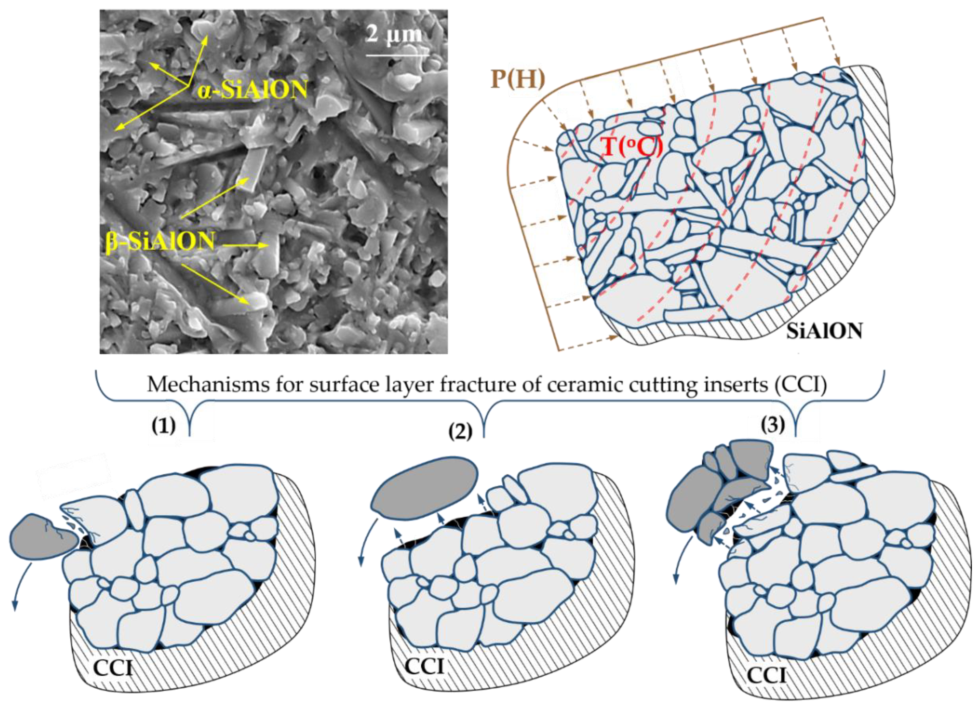
:1. Introduction
- intragranular destruction with gradual separation (abrasion) of microparticles of the surface layer;
- grain-boundary destruction with separation of individual elements of the microstructure;
- mixed destruction, in which there is a separation of grain conglomerates occurring inside the elements of the microstructure.
2. Materials and Methods
2.1. Cutting Tools, Material to Be Processed, and Laboratory Testing Methods
2.2. Preparation of Cutting Ceramic Inserts with Different Condition of the Surface Layer
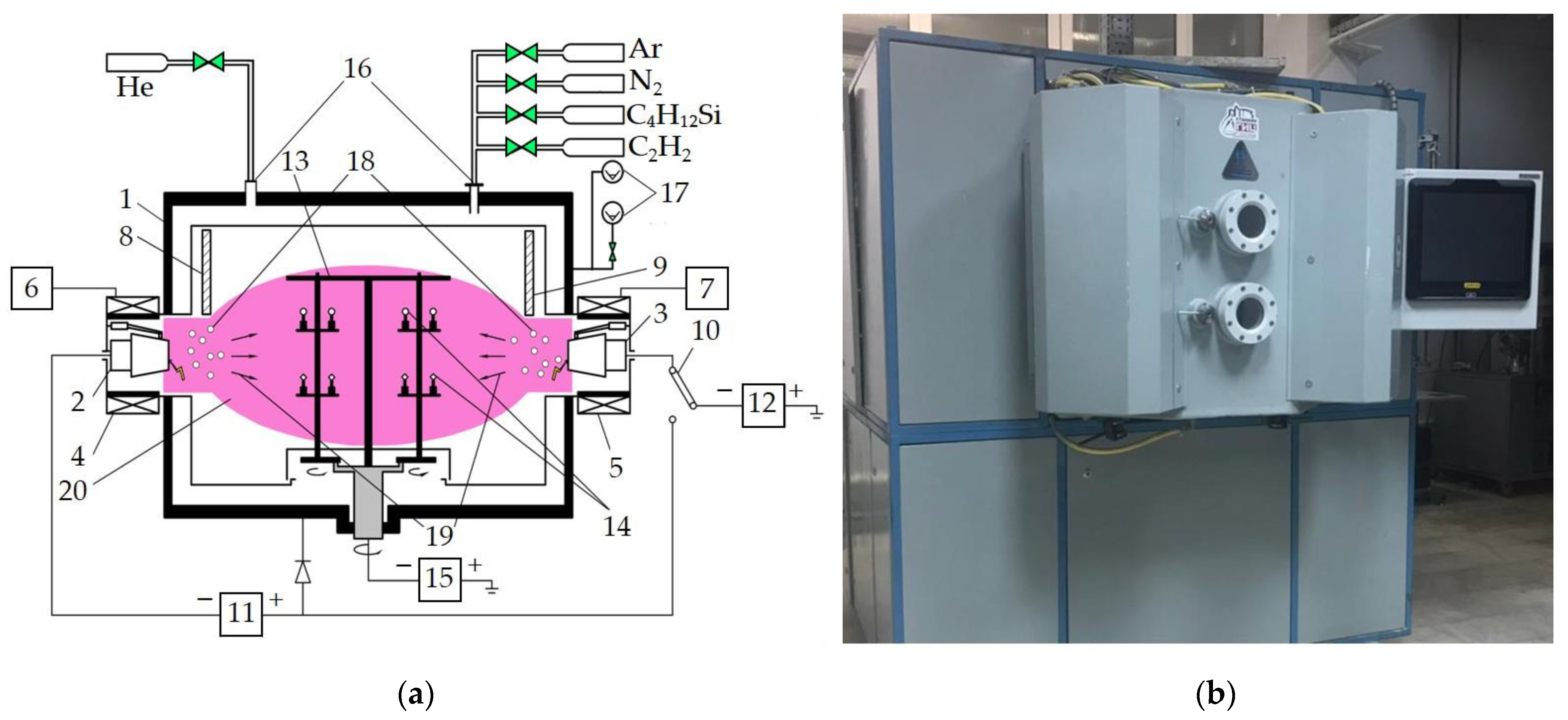
2.3. Coating of Ceramic Inserts
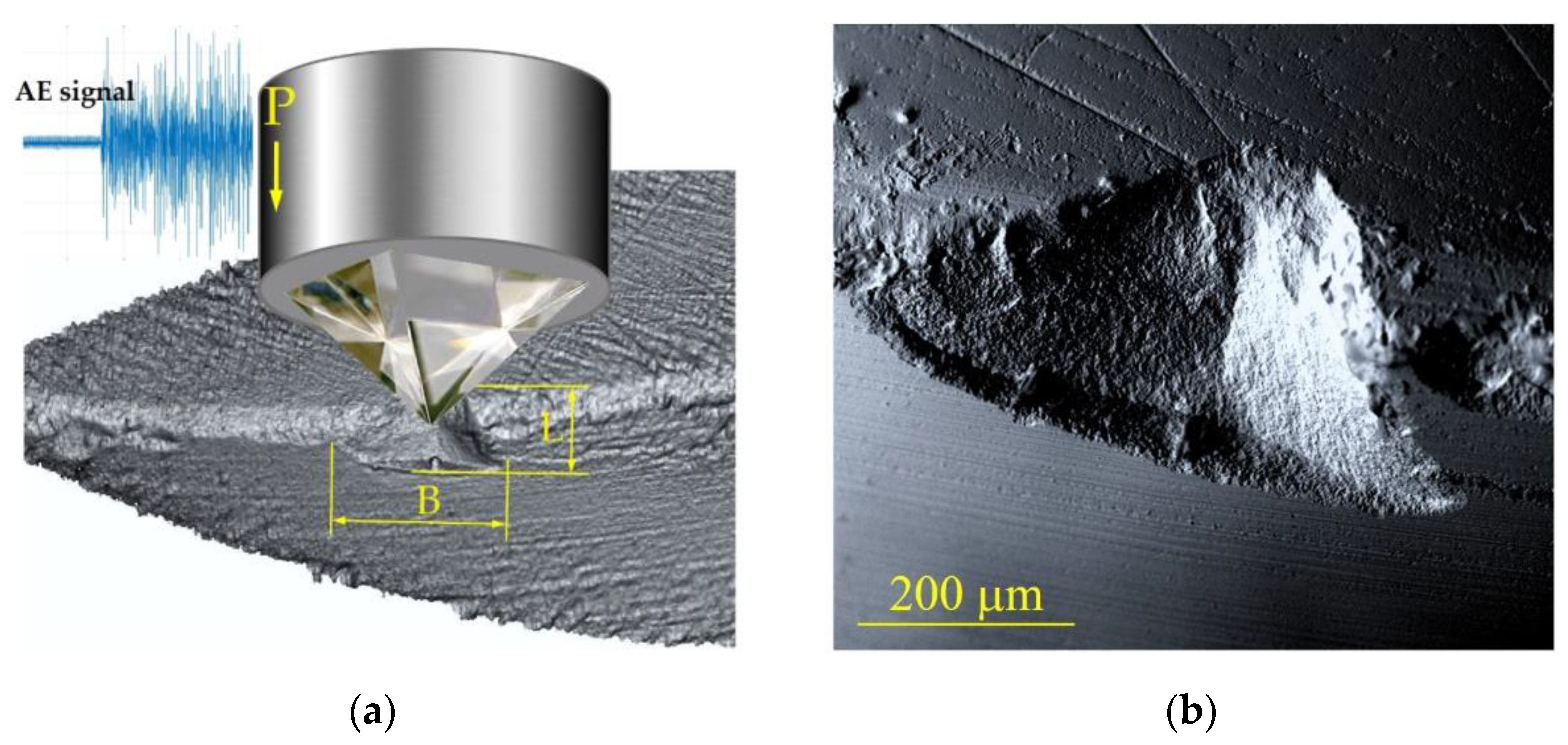
2.4. Investigation of the Properties of the Surface Layer of Ceramic Inserts
3. Results and Discussion
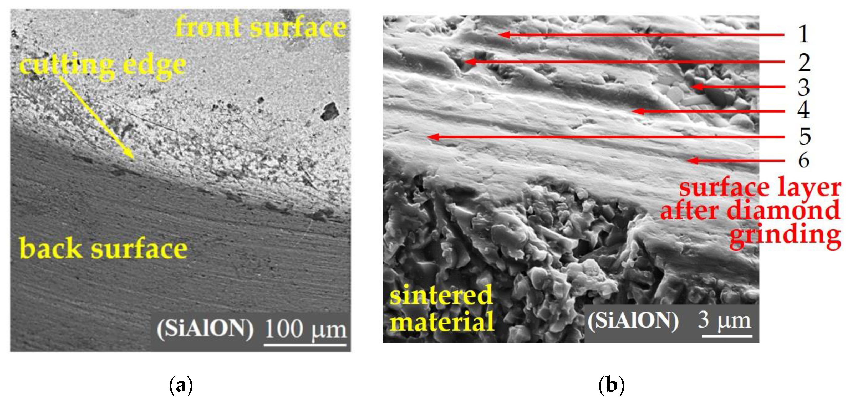
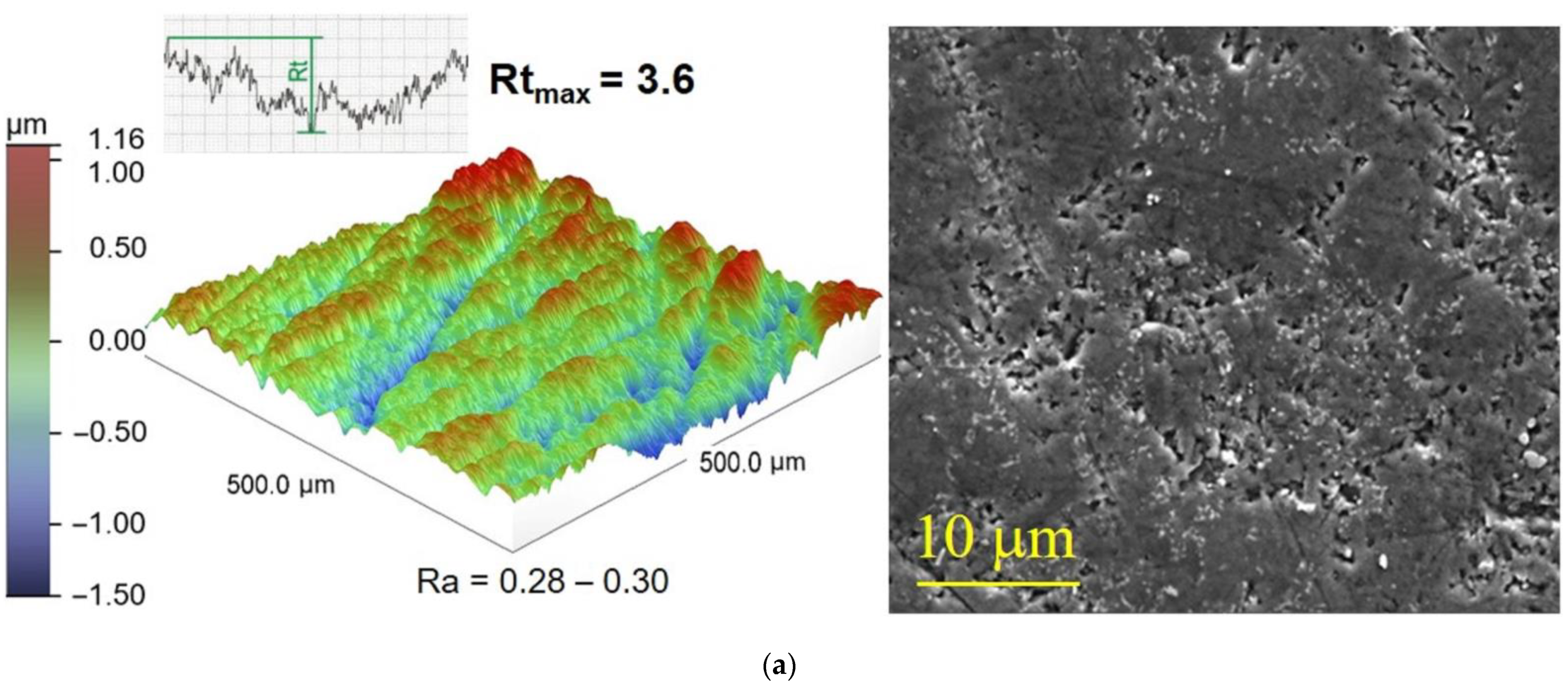
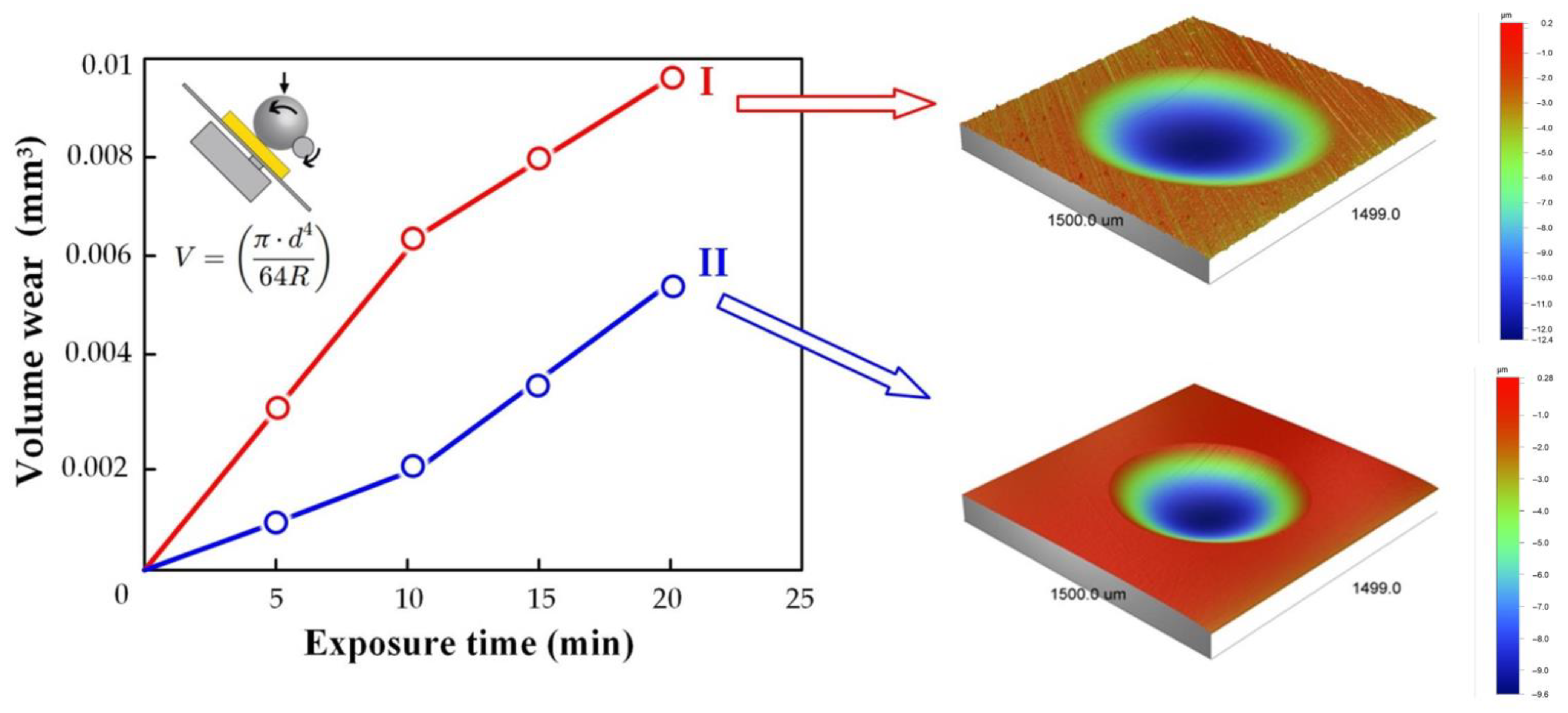
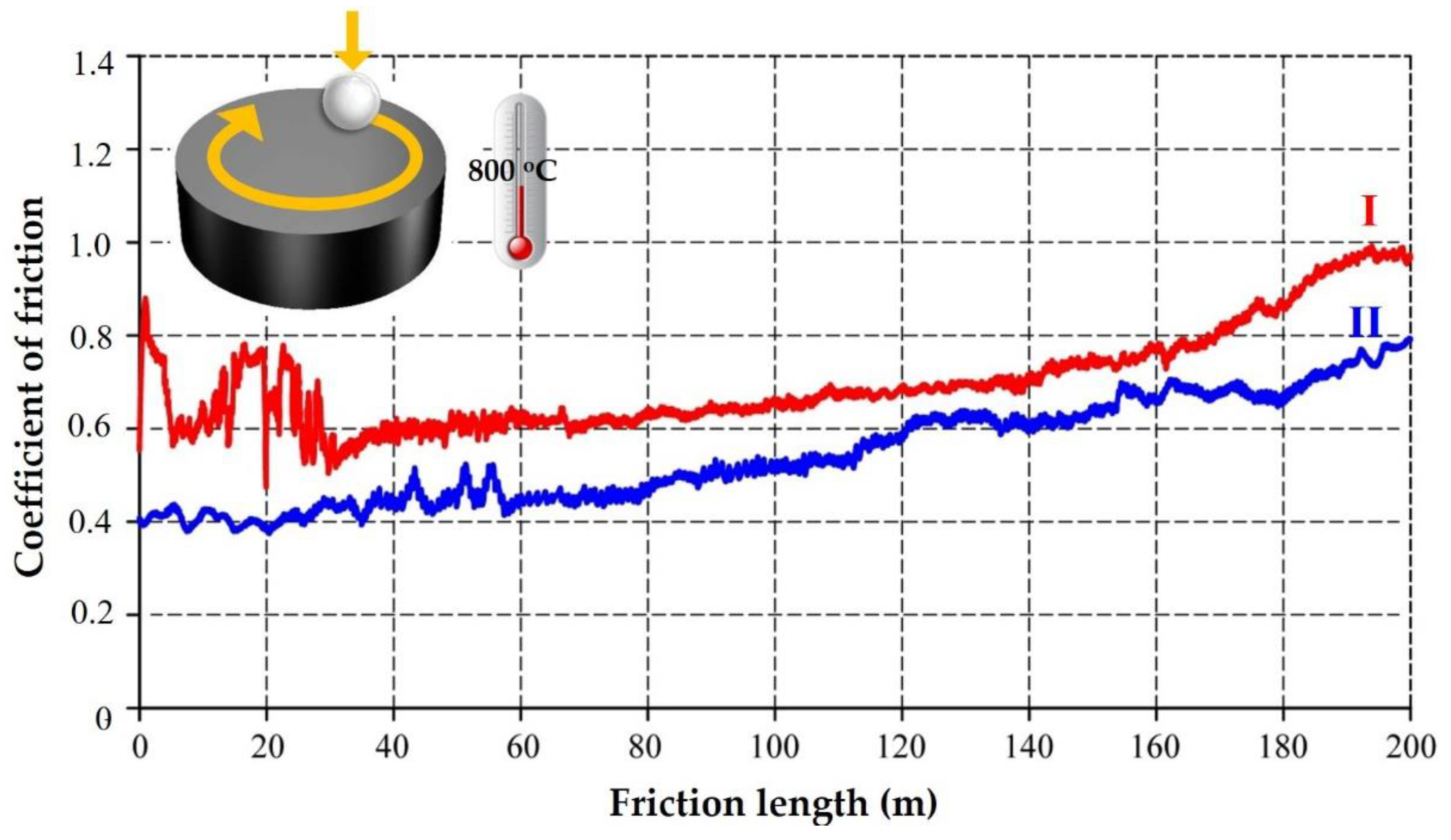
3.1. Influence of Various Diamond Abrasive Machining Methods on the Condition and Characteristics of the Surface Layer of SiAlON Ceramic Inserts
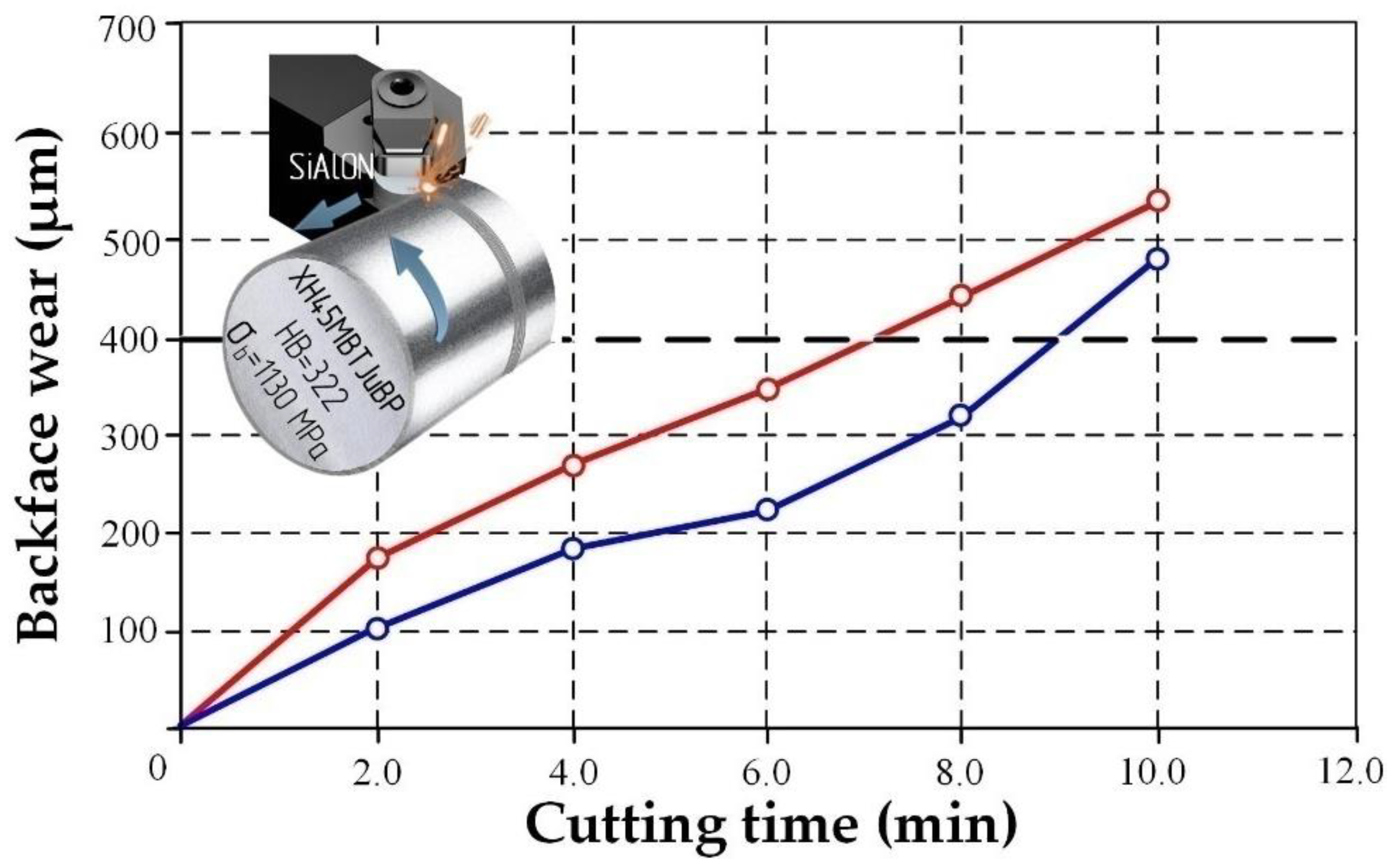
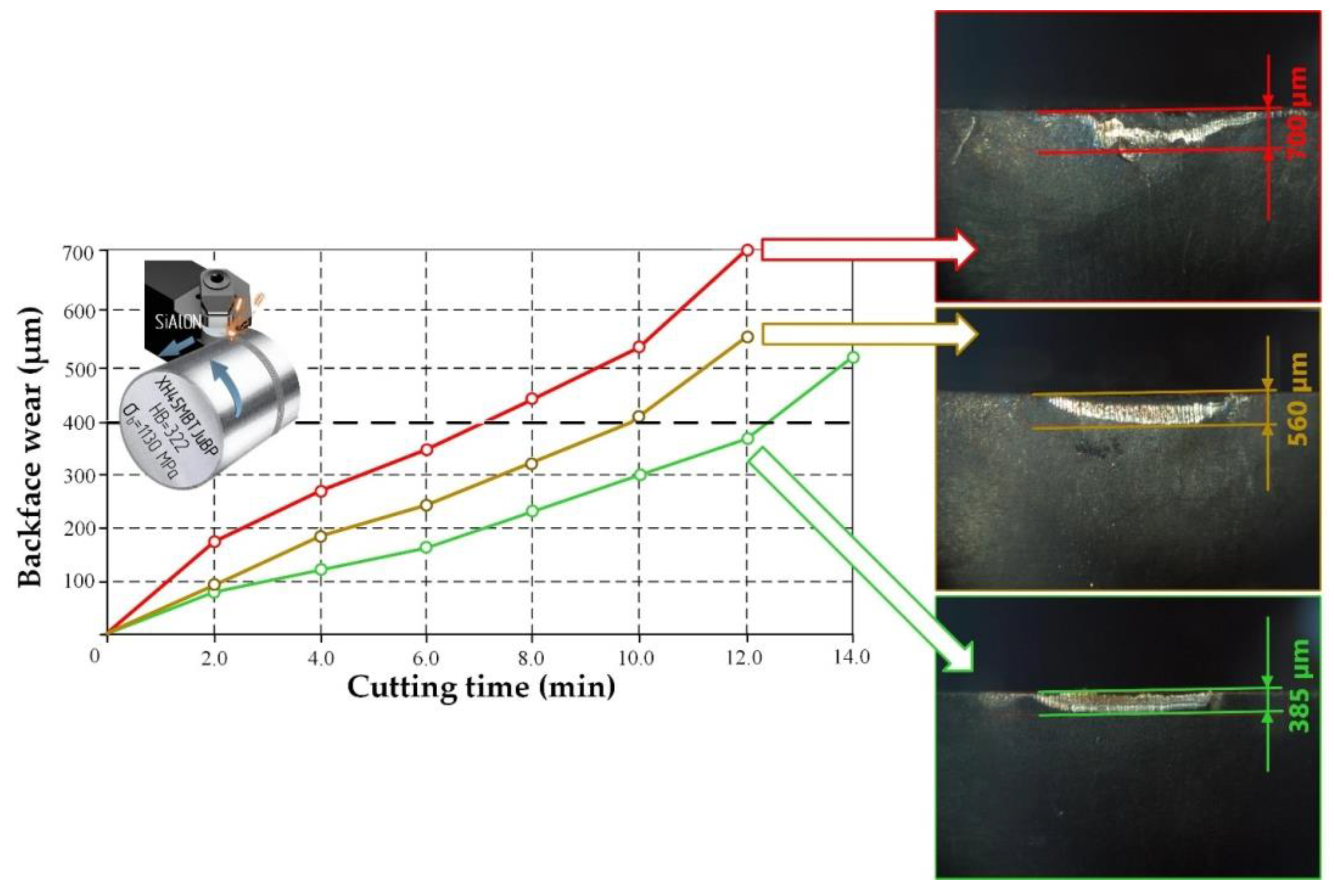
3.2. The Influence of Various Diamond Abrasive Machining Methods on the Durability of SiAlON Ceramic Inserts in Nickel-Based Superalloy Turning
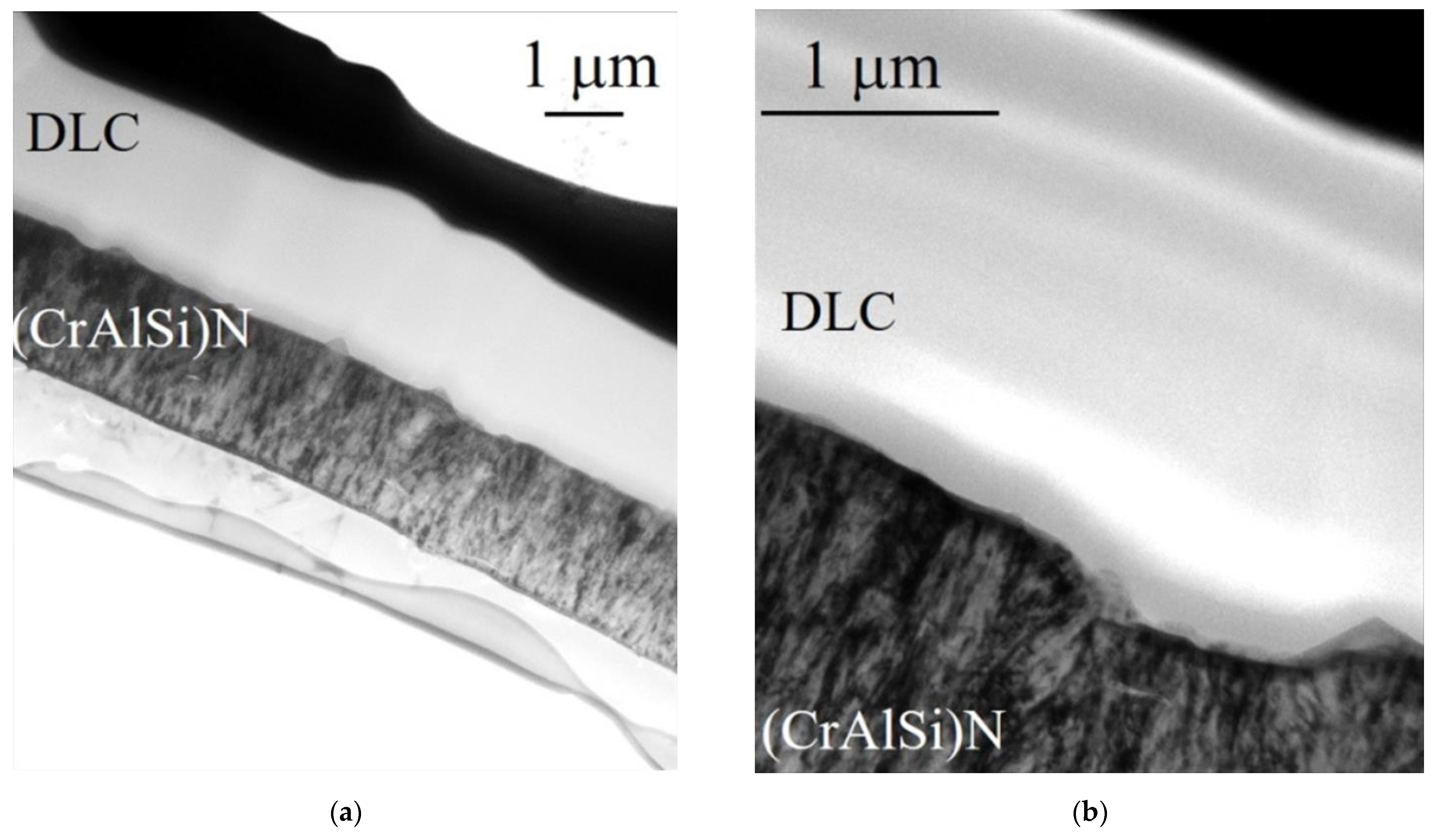
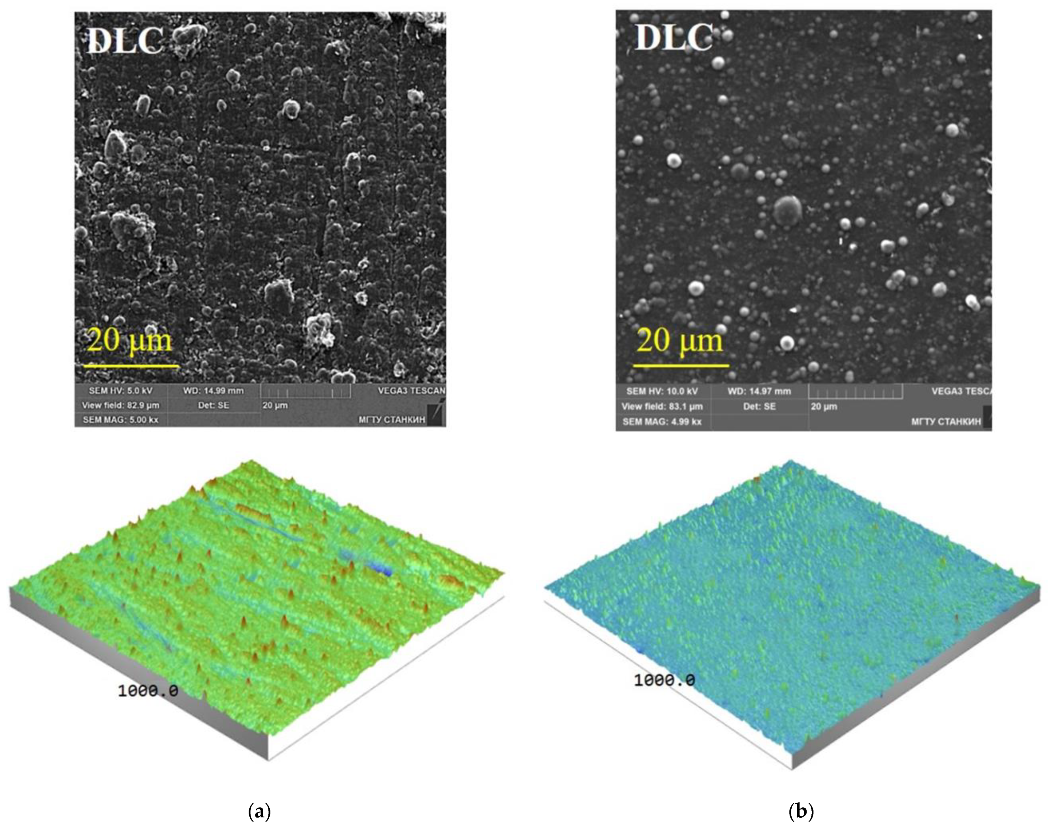
3.3. Influence of the Condition of the Surface Layer of SiAlON Ceramic Inserts on the Quality of Formed (CrAlSi)N/DLC Coatings and Their Wear Resistance in Nickel-Based Superalloy Turning
- SiAlON after diamond grinding (industrially produced CCI), red curve;
- SiAlON after diamond grinding and (CrAlSi)N/DLC coating, brown curve;
- SiAlON after diamond grinding, lapping, polishing, and (CrAlSi)N/DLC coating, green curve.
4. Conclusions
- The surface layer of industrially produced SiAlON ceramic inserts after diamond grinding combines numerous defects such as deep grooves, micro-cracks, ripped-out single grains, and conglomerates of grains of the sintered ceramic. The presence of a defective layer significantly reduces the resistance of the ceramic inserts’ edges to chipping under external mechanical loads and also reduces the contact pads’ ability to resist abrasive wear.
- The conducted studies allowed us to obtain data proving the strong influence of the condition of the surface layer (presence of defects) of SiAlON ceramic inserts on their operational stability (resistance spread) when turning heat-resistant nickel superalloy under conditions of increased cutting speeds and cross-section of the cut layer. At the same time, using various diamond abrasive machining methods, in particular, additional lapping and polishing, allows for minimization of the defective layer formed during diamond grinding and reduction of the resistance spread.
- Deposition of thin-film two-layer (CrAlSi)N/DLC coatings on the surface of industrially produced SiAlON ceramic inserts significantly improves the characteristics of tool ceramics, such as the microhardness of the surface layer increasing, and the coefficient of friction decreasing during high-temperature heating while the abrasion resistance also increases. However, (CrAlSi)N/DLC coatings are not able to “heal” numerous defects of the surface layer but can only reduce the depth of the defective layer. The defects in the surface layer of SiAlON ceramic inserts contribute to forming porous and discontinuous coatings with low adhesive bond strength.
- The maximum effect when turning heat-resistant nickel superalloys under increased cutting speed and cross-section of the cut layer is achieved by using a combined surface treatment method, where lapping and polishing minimize the diamond grinding defects and the subsequent (CrAlSi)N/DLC coating provides an increase in the microhardness of the surface layer and a decrease in the coefficient of friction on the contact surfaces. The developed approach makes it possible to increase the resistance of SiAlON ceramic inserts by a factor of 1.78 compared to industrially produced inserts.
Author Contributions
Funding
Data Availability Statement
Acknowledgments
Conflicts of Interest
References
- Molaiekiya, F.; Stolf, P.; Paiva, J.M.; Bose, B.; Goldsmith, J.; Gey, C.; Engin, S.; Fox-Rabinovich, G.; Veldhuis, S.C. Influence of process parameters on the cutting performance of SiAlON ceramic tools during high-speed dry face milling of hardened Inconel 718. Int. J. Adv. Manuf. Technol. 2019, 105, 1083–1098. [Google Scholar] [CrossRef]
- Zheng, G.; Zhao, J.; Zhou, Y.; Li, A.; Cui, X.; Tian, X. Performance of graded nano-composite ceramic tools in ultra-high-speed milling of Inconel 718. Int. J. Adv. Manuf. Technol. 2013, 67, 2799–2810. [Google Scholar] [CrossRef]
- Grguras, D.; Kern, M.; Pusavec, F. Suitability of the full body ceramic end milling tools for high speed machining of nickel based alloy Inconel 718. Procedia CIRP 2018, 77, 630–633. [Google Scholar] [CrossRef]
- Vereschaka, A.A.; Vereschaka, A.S.; Grigoriev, S.N.; Kirillov, A.K.; Khaustova, O.U. Development and research of environmentally friendly dry technological machining system with compensation of physical function of cutting fluids. Procedia CIRP 2013, 7, 311–316. [Google Scholar] [CrossRef] [Green Version]
- Uhlmann, E.; Hübert, C. Tool grinding of end mill cutting tools made from high performance ceramics and cemented carbides. CIRP Ann. 2011, 60, 359–362. [Google Scholar] [CrossRef]
- Fadok, J. Advanced Gas Turbine Materials, Design and Technology. In Advanced Power Plant Materials, Design and Technology; Roddy, D., Ed.; Woodhead Publishing Series in Energy: Cambridge, UK, 2010; pp. 3–31. [Google Scholar]
- Bitterlich, B.; Bitsch, S.; Friederich, K. SiAlON based ceramic cutting tools. J. Eur. Ceram. Soc. 2008, 28, 989–994. [Google Scholar] [CrossRef]
- Zheng, G.; Zhao, J.; Gao, Z.; Cao, Q. Cutting performance and wear mechanisms of Sialon–Si3N4 graded nano-composite ceramic cutting tools. Int. J. Adv. Manuf. Technol. 2011, 58, 19–28. [Google Scholar] [CrossRef]
- Seleznev, A.; Pinargote, N.W.S.; Smirnov, A. Ceramic Cutting Materials and Tools Suitable for Machining High-Temperature Nickel-Based Alloys: A Review. Metals 2021, 11, 1385. [Google Scholar] [CrossRef]
- Grigoriev, S.N.; Volosova, M.A.; Fedorov, S.V.; Okunkova, A.A.; Pivkin, P.M.; Peretyagin, P.Y.; Ershov, A. Development of DLC-Coated Solid SiAlON/TiN Ceramic End Mills for Nickel Alloy Machining: Problems and Prospects. Coatings 2021, 11, 532. [Google Scholar] [CrossRef]
- Grigoriev, S.N.; Vereschaka, A.A.; Fyodorov, S.V.; Sitnikov, N.N.; Batako, A.D. Comparative analysis of cutting properties and nature of wear of carbide cutting tools with multi-layered nano-structured and gradient coatings produced by using of various deposition methods. Int. J. Adv. Manuf. Technol. 2017, 90, 3421–3435. [Google Scholar] [CrossRef]
- Smirnov, K.L. Sintering of SiAlON ceramics under high-speed thermal treatment. Powder Metall. Met. Ceram. 2012, 51, 76–82. [Google Scholar] [CrossRef]
- Vereschaka, A.S.; Grigoriev, S.N.; Sotova, E.S.; Vereschaka, A.A. Improving the efficiency of the cutting tools made of mixed ceramics by applying modifying nano-scale multilayered coatings. Adv. Mat. Res. 2013, 712, 391–394. [Google Scholar]
- Sharman, A.R.C.; Hughes, J.J.; Ridgway, K. Workpiece surface integrity and tool life issues when turning Inconel 718 nickel-based superalloy. Mach. Sci. Technol. 2004, 8, 399–414. [Google Scholar] [CrossRef]
- Tian, X.; Zhao, J.; Zhao, J.; Gong, Z.; Dong, Y. Effect of cutting speed on cutting forces and wear in high-speed face milling of Inconel 718 with Sialon ceramic tools. Int. J. Adv. Manuf. Technol. 2013, 69, 2669–2678. [Google Scholar] [CrossRef]
- Kuzin, V.V.; Grigoriev, S.N. Method of Investigation of the Stress-Strain State of Surface Layer of Machine Elements from a Sintered Nonuniform Material. Appl. Mech. Mater. 2013, 486, 32–35. [Google Scholar] [CrossRef]
- Rizzo, A.; Goel, S.; Luisa Grilli, M.; Iglesias, R.; Jaworska, L.; Lapkovskis, V.; Novak, P.; Postolnyi, B.O.; Valerini, D. The Critical Raw Materials in Cutting Tools for Machining Applications: A Review. Materials 2020, 13, 1377. [Google Scholar] [CrossRef] [PubMed] [Green Version]
- Yap, T.C. Roles of Cryogenic Cooling in Turning of Superalloys, Ferrous Metals, and Viscoelastic Polymers. Technologies 2019, 7, 63. [Google Scholar] [CrossRef] [Green Version]
- Vereschaka, A.; Tabakov, V.; Grigoriev, S.; Sitnikov, N.; Milovich, F.; Andreev, N.; Bublikov, J. Investigation of wear mechanisms for the rake face of a cutting tool with a multilayer composite nanostructured Cr–CrN-(Ti,Cr,Al,Si)N coating in high-speed steel turning. Wear 2019, 438, 203069. [Google Scholar] [CrossRef]
- Jiang, C.P.; Wu, X.F.; Li, J.; Song, F.; Shao, Y.F.; Xu, X.H.; Yan, P. A study of the mechanism of formation and numerical simulations of crack patterns in ceramics subjected to thermal shock. Acta Mater. 2012, 60, 4540–4550. [Google Scholar] [CrossRef] [Green Version]
- Vereschaka, A.A.; Grigoriev, S.N.; Volosova, M.A.; Batako, A.; Vereschaka, A.S.; Sitnikov, N.N.; Seleznev, A.E. Nano-scale multi-layered coatings for improved efficiency of ceramic cutting tools. Int. J. Adv. Manuf. Technol. 2017, 90, 27–43. [Google Scholar] [CrossRef]
- Kuzin, V.V.; Grigor’ev, S.N.; Volosova, M.A. Microstructural Model of the Surface Layer of Ceramics After Diamond Grinding Taking into Account Its Real Structure and the Conditions of Contact Interaction with Elastic Body. Refract. Ind. Ceram. 2020, 61, 303–308. [Google Scholar] [CrossRef]
- Vigneau, J.; Bordel, P.; Geslot, R. Reliability of сeramic cutting tools. CIRP Ann. 1988, 37, 101–104. [Google Scholar] [CrossRef]
- Wachtman, J.B.; Cannon, W.R.; Matthewson, M.J. Mechanical Properties of Ceramics, 2nd ed.; Wiley: Hoboken, NJ, USA, 2009; p. 479. ISBN 978-0-471-73581-6. [Google Scholar]
- Bensouilah, H.; Aouici, H.; Meddour, I.; Yallese, M.A.; Mabrouki, T.; Girardin, F. Performance of coated and uncoated mixed ceramic tools in hard turning process. Measurement 2016, 82, 1–18. [Google Scholar] [CrossRef]
- Aslantas, K.; Ucun, İ.; Çicek, A. Tool life and wear mechanism of coated and uncoated Al2O3/TiCN mixed ceramic tools in turning hardened alloy steel. Wear 2012, 274, 442–451. [Google Scholar] [CrossRef]
- Matthew, B.; Sam, T.; Keith, R. Correlation between tool life and cutting force coefficient as the basis for a novel method in accelerated MWF performance assessment. Procedia CIRP 2021, 101, 366–369. [Google Scholar] [CrossRef]
- Volosova, M.A.; Stebulyanin, M.M.; Gurin, V.D.; Melnik, Y.A. Influence of Surface Layer Condition of Al2O3+TiC Ceramic Inserts on Quality of Deposited Coatings and Reliability during Hardened Steel Milling. Coatings 2022, 12, 1801. [Google Scholar] [CrossRef]
- Vereschaka, A.; Tabakov, V.; Grigoriev, S.; Sitnikov, N.; Milovich, F.; Andreev, N.; Sotova, C.; Kutina, N. Investigation of the influence of the thickness of nanolayers in wear-resistant layers of Ti-TiN-(Ti,Cr,Al)N coating on destruction in the cutting and wear of carbide cutting tools. Surf. Coat. Technol. 2020, 385, 125402. [Google Scholar] [CrossRef]
- Liu, W.; Chu, Q.; Zeng, J.; He, R.; Wu, H.; Wu, Z.; Wu, S. PVD-CrAlN and TiAlN coated Si3N4 ceramic cutting tools—1. Microstructure, turning performance and wear mechanism. Ceram. Int. 2017, 43, 8999–9004. [Google Scholar] [CrossRef]
- Long, Y.; Zeng, J.; Wu, S. Cutting performance and wear mechanism of Ti–Al–N/Al–Cr–O coated silicon nitride ceramic cutting inserts. Ceram. Int. 2014, 40, 9615–9620. [Google Scholar] [CrossRef]
- Vereschaka, A.; Grigoriev, S.; Tabakov, V.; Migranov, M.; Sitnikov, N.; Milovich, F.; Andreev, N. Influence of the nanostructure of Ti-TiN-(Ti,Al,Cr)N multilayer composite coating on tribological properties and cutting tool life. Tribol. Int. 2020, 150, 106388. [Google Scholar] [CrossRef]
- Grigoriev, S.; Vereschaka, A.; Milovich, F.; Tabakov, V.; Sitnikov, N.; Andreev, N.; Sviridova, T.; Bublikov, J. Investigation of multicomponent nanolayer coatings based on nitrides of Cr, Mo, Zr, Nb, and Al. Surf. Coat. Technol. 2020, 401, 126258. [Google Scholar] [CrossRef]
- Arai, S.A.; Wilson, S.A.; Corbett, J.; Whatmore, R.W. Ultra-precision grinding of PZT ceramics—Surface integrity control and tooling design. Int. J. Mach. Tools Manuf. 2009, 49, 998–1007. [Google Scholar] [CrossRef] [Green Version]
- Canneto, J.J.; Cattani-Lorente, M.; Durual, S.; Wiskott, A.H.W.; Scherrer, S.S. Grinding damage assessment on four high-strength ceramics. Dent. Mater. 2016, 32, 171–182. [Google Scholar] [CrossRef] [PubMed] [Green Version]
- Zhang, C.; Liu, H.; Zhao, Q.; Guo, B.; Wang, J.; Zhang, J. Mechanisms of ductile mode machining for AlON ceramics. Ceram. Int. 2020, 46, 1844–1853. [Google Scholar] [CrossRef]
- Available online: https://www.ctemag.com/news/articles/grinding-ceramic-medical-parts-requires-diamond-grit-patience (accessed on 11 January 2023).
- Grigoriev, S.N.; Volosova, M.A.; Vereschaka, A.A.; Sitnikov, N.N.; Milovich, F.; Bublikov, J.I.; Fyodorov, S.V.; Seleznev, A.E. Properties of (Cr,Al,Si)N-(DLC-Si) composite coatings deposited on a cutting ceramic substrate. Ceram. Int. 2020, 46, 18241–18255. [Google Scholar] [CrossRef]
- Vopát, T.; Sahul, M.; Haršáni, M.; Vortel, O.; Zlámal, T. The Tool Life and Coating-Substrate Adhesion of AlCrSiN-Coated Carbide Cutting Tools Prepared by LARC with Respect to the Edge Preparation and Surface Finishing. Micromachines 2020, 11, 166. [Google Scholar] [CrossRef] [Green Version]
- Bobzin, K.; Brögelmann, T.; Kruppe, N.C.; Carlet, M. Nanocomposite (Ti,Al,Cr,Si)N HPPMS coatings for high performance cutting tools. Surf. Coat. Technol. 2019, 378, 124857. [Google Scholar] [CrossRef]
- Grigoriev, S.; Volosova, M.; Fedorov, S.; Mosyanov, M. Influence of DLC Coatings Deposited by PECVD Technology on the Wear Resistance of Carbide End Mills and Surface Roughness of AlCuMg2 and 41Cr4 Workpieces. Coatings 2020, 10, 1038. [Google Scholar] [CrossRef]
- Wei, C.; Yang, J.-F. A finite element analysis of the effects of residual stress, substrate roughness and non-uniform stress distribution on the mechanical properties of diamond-like carbon films. Diam. Relat. Mater. 2011, 20, 839–844. [Google Scholar] [CrossRef]
- Lubwama, M.; Corcoran, B.; McDonnell, K.A.; Dowling, D. Flexibility and frictional behaviour of DLC and Si-DLC films deposited on nitrile rubber. Surf. Coat. Technol. 2014, 239, 84–94. [Google Scholar] [CrossRef]
- Hainsworth, S.V.; Uhure, N.J. Diamond like carbon coatings for tribology: Production techniques, characterisation methods and applications. Int. Mat. Rev. 2007, 52, 153–174. [Google Scholar] [CrossRef]
- Nakazawa, H.; Kamata, R.; Miura, S.; Okuno, S. Effects of frequency of pulsed substrate bias on structure and properties of silicon-doped diamond-like carbon films by plasma deposition. Thin Solid Film. 2015, 574, 93–98. [Google Scholar] [CrossRef]
- Martinez-Martinez, D.; De Hosson, J.T.M. On the deposition and properties of DLC protective coatings on elastomers: A critical review. Surf. Coat. Technol. 2014, 258, 677–690. [Google Scholar] [CrossRef]
- Liu, X.Q.; Yang, J.; Hao, J.Y.; Zheng, J.Y.; Gong, Q.Y.; Liu, W.M. A near-frictionless and extremely elastic hydrogenated amorphous carbon film with self-assembled dual nanostructure. Adv. Mater. 2012, 24, 4614–4617. [Google Scholar] [CrossRef] [PubMed]
- Zou, C.W.; Wang, H.J.; Feng, L.; Xue, S.W. Effects of Cr concentrations on the microstructure, hardness, and temperature-dependent tribological properties of Cr-DLC coatings. Appl. Surf. Sci. 2013, 286, 137–141. [Google Scholar] [CrossRef]
- Wu, Y.; Li, H.; Ji, L.; Ye, Y.; Chen, J.; Zhou, H. Vacuum tribological properties of a-C:H film in relation to internal stress and applied load. Tribol. Int. 2014, 71, 82–87. [Google Scholar] [CrossRef]
- Zhang, T.F.; Pu, J.J.; Xia, Q.X.; Son, M.J.; Kim, K.H. Microstructure and nano-wear property of Si-doped diamond like carbon films deposited by a hybrid sputtering system. Mater. Today Proc. 2016, 3, S190–S196. [Google Scholar] [CrossRef]
- Grigoriev, S.N.; Melnik, Y.A.; Metel, A.S.; Panin, V.V.; Prudnikov, V.V. A compact vapor source of conductive target material sputtered by 3-keV ions at 0.05-Pa pressure. Instrum. Exp. Technol. 2009, 52, 731–737. [Google Scholar] [CrossRef]
- Metel, A.; Bolbukov, V.; Volosova, M.; Grigoriev, S.; Melnik, Y. Equipment for deposition of thin metallic films bombarded by fast argon atoms. Instrum. Exp. Technol. 2014, 57, 345–351. [Google Scholar] [CrossRef]
- Sobol, O.V.; Andreev, A.A.; Grigoriev, S.N.; Volosova, M.A.; Gorban, V.F. Vacuum-arc multilayer nanostructured TiN/Ti coatings: Structure, stress state, properties. Met. Sci. Heat Treat. 2012, 54, 28–33. [Google Scholar] [CrossRef]
- Sobol, O.V.; Andreev, A.A.; Grigoriev, S.N.; Gorban, V.F.; Volosova, M.A.; Aleshin, S.V.; Stolbovoi, V.A. Effect of high-voltage pulses on the structure and properties of titanium nitride vacuum-arc coatings. Met. Sci. Heat Treat. 2012, 54, 195–203. [Google Scholar] [CrossRef]
- Metel, A.S.; Grigoriev, S.N.; Melnik, Y.A.; Bolbukov, V.P. Characteristics of a fast neutral atom source with electrons injected into the source through its emissive grid from the vacuum chamber. Instrum. Exp. Technol. 2012, 55, 288–293. [Google Scholar] [CrossRef]
- Mei, Z.; Lu, Y.; Lou, Y.; Yu, P.; Sun, M.; Tan, X.; Zhang, J.; Yue, L.; Yu, H. Determination of Hardness and Fracture Toughness of Y-TZP Manufactured by Digital Light Processing through the Indentation Technique. Biomed Res. Int. 2021, 2021, 11. [Google Scholar]
- Gogotsi, G.A. Edge chipping resistance of ceramics: Problems of test method. J. Adv. Ceram. 2013, 2, 370–377. [Google Scholar] [CrossRef] [Green Version]
- Gogotsi, G.A.; Galenko, V.Y. Sensitivity of Brittle Materials to Local Stress Concentrations on Their Fracture. Strength Mater. 2022, 54, 250–255. [Google Scholar] [CrossRef]
- Feng, P.; Borghesani, P.; Smith, W.A.; Randall, R.B.; Peng, Z. A Review on the Relationships Between Acoustic Emission, Friction and Wear in Mechanical Systems. Appl. Mech. Rev. 2020, 72, 020801. [Google Scholar] [CrossRef]
- Babici, L.M.; Tudor, A.; Romeu, J. Stick-Slip Phenomena and Acoustic Emission in the Hertzian Linear Contact. Appl. Sci. 2022, 12, 9527. [Google Scholar] [CrossRef]
- Hase, A. Early Detection and Identification of Fatigue Damage in Thrust Ball Bearings by an Acoustic Emission Technique. Lubricants 2020, 8, 37. [Google Scholar] [CrossRef] [Green Version]
- Hase, A.; Mishina, H.; Wada, M. Correlation between Features of Acoustic Emission Signals and Mechanical Wear Mechanisms. Wear 2012, 292, 144–150. [Google Scholar] [CrossRef]
- Xu, C.; Li, B.; Wu, T. Wear Characterization under Sliding–Rolling Contact Using Friction-Induced Vibration Features. Proc. Inst. Mech. Eng. Part J. Eng. Tribol. 2022, 236, 634–647. [Google Scholar] [CrossRef]
- Steier, V.F.; Ashiuchi, E.S.; Reißig, L.; Araújo, J.A. Effect of a Deep Cryogenic Treatment on Wear and Microstructure of a 6101 Aluminum Alloy. Adv. Mater. Sci. Eng. 2016, 2016, 12. [Google Scholar] [CrossRef] [Green Version]
- Shulepov, I.A.; Kashkarov, E.B.; Stepanov, I.B.; Syrtanov, M.S.; Sutygina, A.N.; Shanenkov, I.; Obrosov, A.; Weiß, S. The Formation of Composite Ti-Al-N Coatings Using Filtered Vacuum Arc Deposition with Separate Cathodes. Metals 2017, 7, 497. [Google Scholar] [CrossRef]
- Grigoriev, S.N.; Teleshevskii, V.I. Measurement Problems in Technological Shaping Processes. Meas. Tech. 2011, 54, 744–749. [Google Scholar] [CrossRef]
- Choudhary, R.K.; Mishra, P. Use of Acoustic Emission During Scratch Testing for Understanding Adhesion Behavior of Aluminum Nitride Coatings. J. Mater. Eng Perform 2016, 25, 2454–2461. [Google Scholar] [CrossRef]
- Vereschaka, A.A.; Volosova, M.A.; Grigoriev, S.N.; Vereschaka, A.S. Development of wear-resistant complex for high-speed steel tool when using process of combined cathodic vacuum arc deposition. Procedia CIRP 2013, 9, 8–12. [Google Scholar] [CrossRef] [Green Version]
- Kazlauskas, D.; Jankauskas, V.; Tučkutė, S. Research on Tribological Characteristics of Hard Metal WC-Co Tools with TiAlN and CrN PVD Coatings for Processing Solid Oak Wood. Coatings 2020, 10, 632. [Google Scholar] [CrossRef]
- Shao, L.; Zhou, Y.; Fang, W.; Wang, J.; Wang, X.; Deng, Q.; Lyu, B. Preparation of Cemented Carbide Insert Cutting Edge by Flexible Fiber-Assisted Shear Thickening Polishing Method. Micromachines 2022, 13, 1631. [Google Scholar] [CrossRef]
- Volosova, M.; Grigoriev, S.; Metel, A.; Shein, A. The Role of Thin-Film Vacuum-Plasma Coatings and Their Influence on the Efficiency of Ceramic Cutting Inserts. Coatings 2018, 8, 287. [Google Scholar] [CrossRef] [Green Version]
- Kiryukhantsev-Korneev, P.; Sytchenko, A.; Sheveyko, A.; Moskovskikh, D.; Vorotylo, S. Two-Layer Nanocomposite TiC-Based Coatings Produced by a Combination of Pulsed Cathodic Arc Evaporation and Vacuum Electro-Spark Alloying. Materials 2020, 13, 547. [Google Scholar] [CrossRef] [Green Version]
- Mpilitos, C.; Amanatiadis, S.; Apostolidis, G.; Zygiridis, T.; Kantartzis, N.; Karagiannis, G. Development of a Transmission Line Model for the Thickness Prediction of Thin Films via the Infrared Interference Method. Technologies 2018, 6, 122. [Google Scholar] [CrossRef] [Green Version]
- Volosova, M.A.; Fyodorov, S.V.; Opleshin, S.; Mosyanov, M. Wear Resistance and Titanium Adhesion of Cathodic Arc Deposited Multi-Component Coatings for Carbide End Mills at the Trochoidal Milling of Titanium Alloy. Technologies 2020, 8, 38. [Google Scholar] [CrossRef]
- Grigoriev, S.; Vereschaka, A.; Zelenkov, V.; Sitnikov, N.; Bublikov, J.; Milovich, F.; Andreev, N.; Mustafaev, E. Specific features of the structure and properties of arc-PVD coatings depending on the spatial arrangement of the sample in the chamber. Vacuum 2022, 200, 111047. [Google Scholar] [CrossRef]
- Grigoriev, S.; Vereschaka, A.; Zelenkov, V.; Sitnikov, N.; Bublikov, J.; Milovich, F.; Andreev, N.; Sotova, C. Investigation of the influence of the features of the deposition process on the structural features of microparticles in PVD coatings. Vacuum 2022, 202, 111144. [Google Scholar] [CrossRef]
- Grigoriev, S.; Volosova, M.; Fyodorov, S.; Lyakhovetskiy, M.; Seleznev, A. DLC-coating Application to Improve the Durability of Ceramic Tools. J. Mater. Eng Perform 2019, 28, 4415–4426. [Google Scholar] [CrossRef]


| Element | Ni | Fe | Cr | Mo | Nb | W | Ti | Al | C, Si, Mn, S, P |
| Content (%) | 45.3 | 27.9 | 15.0 | 4.0 | 1.3 | 2.5 | 2.0 | 1.0 | 1.0 |
| Stage of the Process | Technological Modes | Measuring Units | Values |
|---|---|---|---|
| Sample heating | Chamber pressure | Pa | 0.03 |
| Rotation speed of the tooling with samples (constant at all stages) | rpm | 5 | |
| Heating temperature | °C | 500 | |
| Heating time | min | 60 | |
| Purification in a gas discharge | Composition of the working gas | - | Ar |
| Chamber pressure | Pa | 1.2 | |
| Bias voltage | V | −650 | |
| Chamber temperature | °C | 500 | |
| Current at the cathode AlSi (open shutter) | A | 90 | |
| Current at the cathode Cr (closed shutter) | A | 105 | |
| Purification time | min | 20 | |
| Ion purification | Composition of the working gas | - | Ar |
| Chamber pressure | Pa | 2.2 | |
| Bias voltage | V | −800 | |
| Chamber temperature | °C | 500 | |
| Current at the cathode Cr | A | 90 | |
| Purification time | min | 20 | |
| (CrAlSi)N sublayer deposition | Composition of the working gas | - | 95% N₂/5% Ar |
| Chamber pressure | Pa | 0.9 | |
| Bias voltage | V | −40 | |
| Chamber temperature | °C | 500 | |
| Current at the cathode AlSi | A | 100 | |
| Current at the cathode Cr | A | 100 | |
| Deposition time | min | 90 | |
| Gradient DLC-Si layer deposition | Composition of the working gas | - | 72% N₂/20% Ar/8% C₄H₁₂Si |
| Chamber pressure | Pa | 1.5 | |
| Bias voltage | V | −500 | |
| Chamber temperature | °C | 180 | |
| Deposition time | min | 20 | |
| External DLC-layer deposition | Composition of the working gas | - | 55% Ar/45% C₂H₂ |
| Chamber pressure | Pa | 0.8 | |
| Bias voltage | V | −500 | |
| Chamber temperature | °C | 180 | |
| Deposition time | min | 100 |
| No. | Diamond Abrasive Machining | Average Values of the Surface Layer Characteristics (According to the Measurement Result of 10 Samples) | |||
|---|---|---|---|---|---|
| Crack Resistance Kc, MPa·m1/2 | Microhardness HV, GPa | Roughness Ra, μm | Defect Layer Depth Rt, μm | ||
| 1 | Diamond grinding (group I) | 4.91 ± 0.35 | 15.99 ± 0.05 | 0.29 ± 0.025 | 3.1 ± 0.031 |
| 2 | Diamond grinding, lapping, and polishing (group II) | 5.26 ± 0.27 | 16.09 ± 0.05 | 0.019 ± 0.002 | 0.29 ± 0.032 |
| No. | Destructive Load, N | Diamond Abrasive Machining Methods | |
|---|---|---|---|
| Diamond Grinding (Group I) | Diamond Grinding, Lapping, and Polishing (Group II) | ||
| 1 | Average value | 28.9 | 37.6 |
| 2 | Max value | 33 | 40 |
| 3 | Min value | 26 | 36 |
Disclaimer/Publisher’s Note: The statements, opinions and data contained in all publications are solely those of the individual author(s) and contributor(s) and not of MDPI and/or the editor(s). MDPI and/or the editor(s) disclaim responsibility for any injury to people or property resulting from any ideas, methods, instructions or products referred to in the content. |
© 2023 by the authors. Licensee MDPI, Basel, Switzerland. This article is an open access article distributed under the terms and conditions of the Creative Commons Attribution (CC BY) license (https://creativecommons.org/licenses/by/4.0/).
Share and Cite
Grigoriev, S.N.; Volosova, M.A.; Okunkova, A.A. Investigation of Surface Layer Condition of SiAlON Ceramic Inserts and Its Influence on Tool Durability When Turning Nickel-Based Superalloy. Technologies 2023, 11, 11. https://doi.org/10.3390/technologies11010011
Grigoriev SN, Volosova MA, Okunkova AA. Investigation of Surface Layer Condition of SiAlON Ceramic Inserts and Its Influence on Tool Durability When Turning Nickel-Based Superalloy. Technologies. 2023; 11(1):11. https://doi.org/10.3390/technologies11010011
Chicago/Turabian StyleGrigoriev, Sergey N., Marina A. Volosova, and Anna A. Okunkova. 2023. "Investigation of Surface Layer Condition of SiAlON Ceramic Inserts and Its Influence on Tool Durability When Turning Nickel-Based Superalloy" Technologies 11, no. 1: 11. https://doi.org/10.3390/technologies11010011