
A Thermo-Mechanical Properties Evaluation of Multi-Directional Carbon/Carbon Composite Materials in Aerospace Applications


1
Department of Aviation Maintenance Engineering, Silla University, Sasang-gu, Busan 46958, Korea
2
School of Mechanical Engineering, Chungnam National University, Daejeon 34134, Korea
*
Author to whom correspondence should be addressed.
Aerospace 2022, 9(8), 461; https://doi.org/10.3390/aerospace9080461
Submission received: 18 July 2022
/
Revised: 18 August 2022
/
Accepted: 19 August 2022
/
Published: 20 August 2022
(This article belongs to the Topic Composites in Aerospace and Mechanical Engineering)
Abstract
:Carbon/carbon (C/C) composite materials are widely used in aerospace structures operating in high temperature environments based on their high performance thermal and mechanical properties. The C/C composite material has a yarn architecture in which fiber bundles in different directions cross each other, and it is also divided into architecture types, such as 3-D orthogonal, 4-D in-plane, and 4-D diagonal, according to the arrangement of the fiber bundles. The thermo-mechanical performance of the carbon/carbon composite material may vary depending on the yarn architecture, and the material properties are also tailored according to constituent materials, such as fiber and matrix, and manufacturing parameters, such as yarn size, yarn spacing, and fiber volume fraction. In this paper, three types of geometric models are defined for repeating unit cells (RUCs), according to the yarn architecture of the C/C composite material, and the effective stiffness was predicted by applying the iso-strain assumption and stress averaging technique. In addition, the thermo-mechanical characteristics according to the yarn architecture and fiber volume fraction of RUC were compared and evaluated.
1. Introduction
Carbon/carbon (C/C) composite material is a type of composite material applied with carbon fiber and carbon matrix. The carbon material has high stiffness and strength as well as excellent thermal and chemical stability in high temperature environments. Based on these high-performance thermo-mechanical properties, it is widely used as a material for aerospace structures, such as throat nozzle of solid rocket systems operated in a high-temperature environment, nose tips, and leading edges in high performance aerospace vehicles [1,2,3].
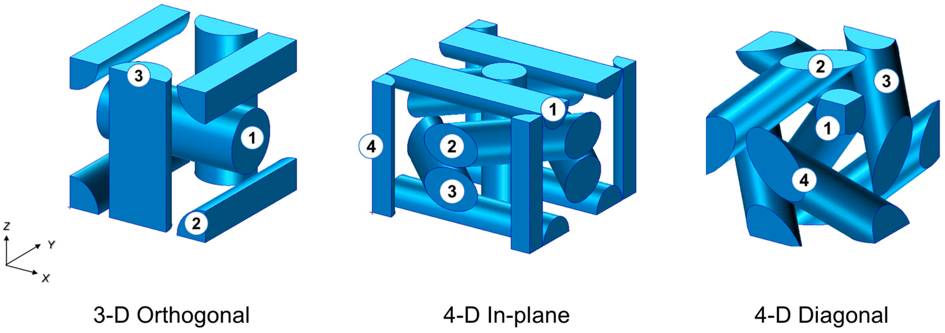
The C/C composite material has a yarn architecture according to fiber bundles in different directions cross each other. Typical C/C composites according to yarn architecture are divided as follows: 3-D orthogonal, 4-D in-plane, and 4-D diagonal composite. The ‘n-D’ means the number of fiber bundle directions. The thermo-mechanical properties of the C/C composite material can be tailored according to the yarn architecture, the type of constituent materials (fiber and matrix), and manufacturing parameters, such as yarn size, yarn spacing, and fiber volume fraction. In the preliminary design stage of the aerospace structure, it is possible to select the constituent materials and manufacturing parameters of the composite material. Therefore, if the thermo-mechanical properties of C/C composite materials that change according to various materials and manufacturing parameters can be predicted, it will be possible to reduce the excessive testing cost required to obtain material properties, as well as satisfy the thermo-mechanical performance and optimize the structure weight. For this reason, several studies have been conducted on the prediction of thermo-mechanical properties of C/C composite materials according to the yarn architecture, type of constituents, and manufacturing parameters [4,5,6,7].
Chou and Ishikawa [8] studied analytical models such as the mosaic model, fiber undulation model, and bridging model to predict the mechanical properties of two-dimensional plane weave composite materials. Ko et al. [9] proposed a fabric geometry model (FGM) for predicting the effective stiffness for a three-dimensional braided composite material based on classical laminate theory and the energy method. Pastore and Gowayed [10] suggested a modified FGM to predict the elastic properties of the textile composite. Ma et al. [11] studied the fiber inclination model (FIM) using a repeating unit cell (RUC) of three-dimensional braided textile. Foye et al. [12] predicted the mechanical properties of plain weave, satin weave, and braided composites by using the concept of a sub-cell in the repeating unit cell. Xu et al. [13] suggested the method of effective properties prediction through macro- and micro-scale finite element modeling and analysis of biaxial and triaxial braided composites. Naik et al. [14,15,16] proposed a technique for predicting thermo-mechanical properties by considering the geometrical configuration of the fiber bundle structure of various types of two-dimensional CFRP (carbon fiber reinforced epoxy) textile composite materials such as plane weave, satin weave, twill weave, and braiding. Delneste et al. [17] studied a technique for predicting effective stiffness using an inelastic finite element model defined for a C/C composite material with a 4-D diagonal yarn architecture. In addition, the mechanical properties of the C/C composite materials were evaluated in each direction and compared with the 4-D C/C ring structure test results. Sharma [18] conducted a study to predict the effective stiffness of 4-D in-plane C/C composite materials through finite element analysis. In this case, a finite element model of a 4-D in-plane unit cell was created, and the effects of matrix cracking and fiber bundle/matrix interfacial cracking were examined using cohesive interaction. Wang et al. [19] conducted a study to predict the effective properties and coefficient of thermal expansion (CTE) of axial braided C/C composite materials. In this case, a finite element model for RVE (representative volume element) was created by considering the 4-D in-plane yarn architecture, and the characteristics of effective mechanical properties and CTEs according to braiding manufacturing parameters were evaluated. Rao et al. [20] evaluated the mechanical properties of C/C composite materials having a yarn architecture of 3-D orthogonal, 3-D plain weave, and 4-D in-plane types. A finite element model was defined for each repeating unit cell, and mechanical properties were predicted through finite element analysis applying periodic boundary conditions [21].
The study of predicting thermo-mechanical properties of general carbon/epoxy textile composite materials was conducted based on a semi-numerical method based on geometric modeling according to the fiber yarn architecture. However, in the case of carbon/carbon composite materials, thermo-mechanical properties were predicted and evaluated mostly based on finite element analysis. The finite element analysis has the advantage that more detailed analysis is possible considering the porosity that exists at the matrix or fiber bundle interface. However, it has the disadvantage that it requires a lot of time and cost to perform repeated analysis in consideration of various manufacturing parameters, such as the type of constituent material, the diameter of the fiber bundle, and the fiber volume fraction. In the initial design stage of aerospace structures, it is necessary to appropriately select the types of constituent materials and manufacturing parameters for the purpose of optimizing structural performance and weight. In this case, it would be more effective to predict and evaluate the thermo-mechanical properties using a semi-numeric method that is relatively suitable for iterative analysis.
In this paper, we define a geometric model for the repeating unit cell of C/C composite materials with three types of fiber yarn architecture, such as 3-D orthogonal, 4-D in-plane, and 4-D diagonal type, and predict thermo-mechanical properties using the semi-numerical method based on the stiffness averaging technique. The effective mechanical properties and coefficient of thermal expansion of the C/C composite materials were predicted by applying the stiffness averaging technique based on the iso-strain assumption on the repeating unit cell. In addition, the thermo-mechanical performance of the C/C composite material was compared and evaluated according to the change of manufacturing parameters, such as the type of yarn architecture and the fiber volume fraction.
2. Yarn Architectures of Multi-Directional C/C Composites
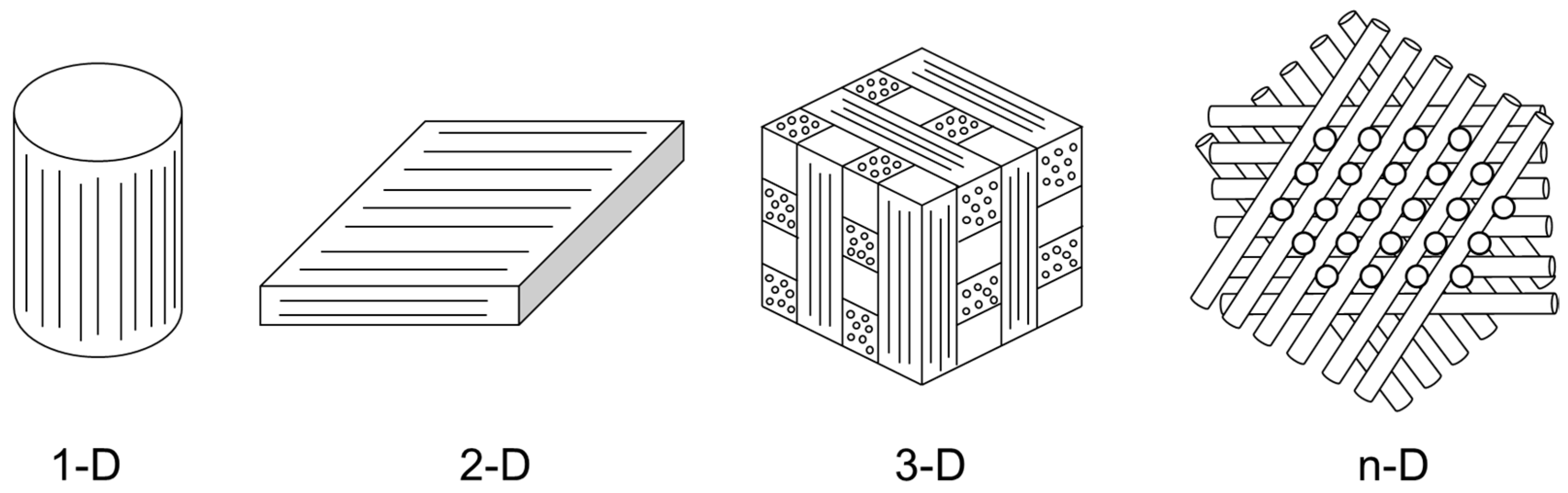
The carbon/carbon composite materials have various types of architectures from 1-dimension to n-dimension, as shown in Figure 1, depending on the application method of unidirectional fiber tow, tape, woven cloth, etc. [3]. Due to the multiformity of these materials, the mechanical properties of the materials can be readily tailored as required. This is a characteristic similar to the case of a typical textile composite material that can be manufactured in various ways with two-dimensional and three-dimensional weaving and braiding composite materials.
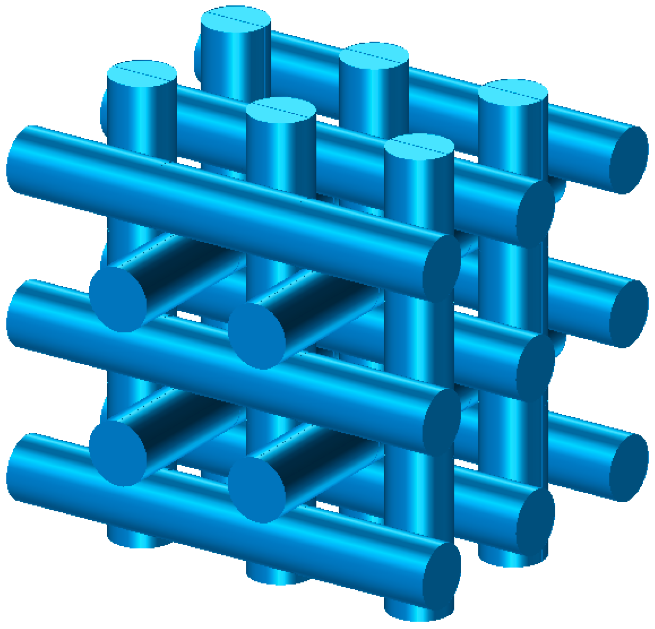
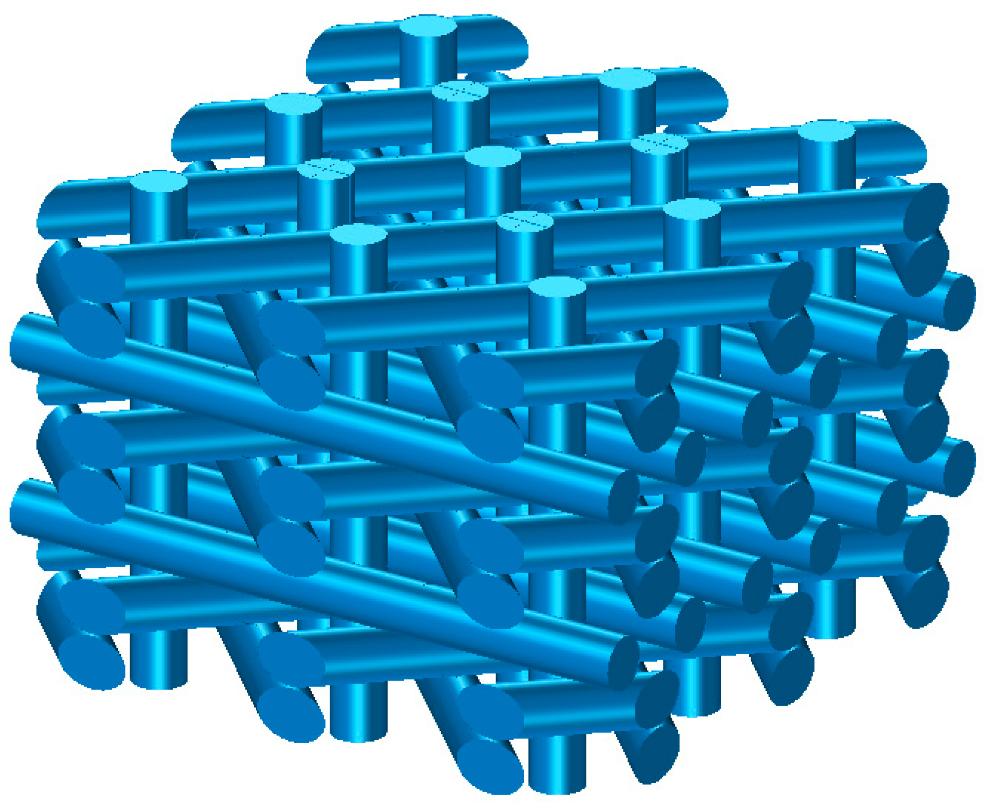
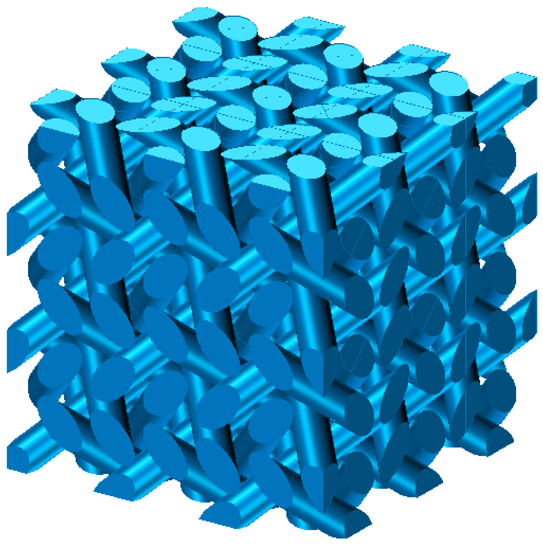
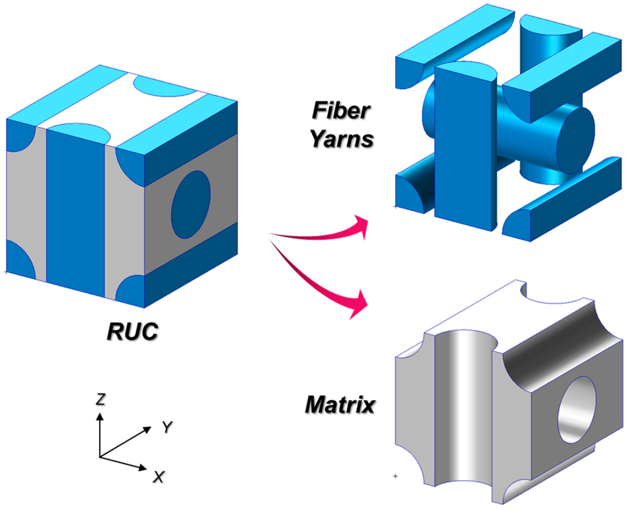
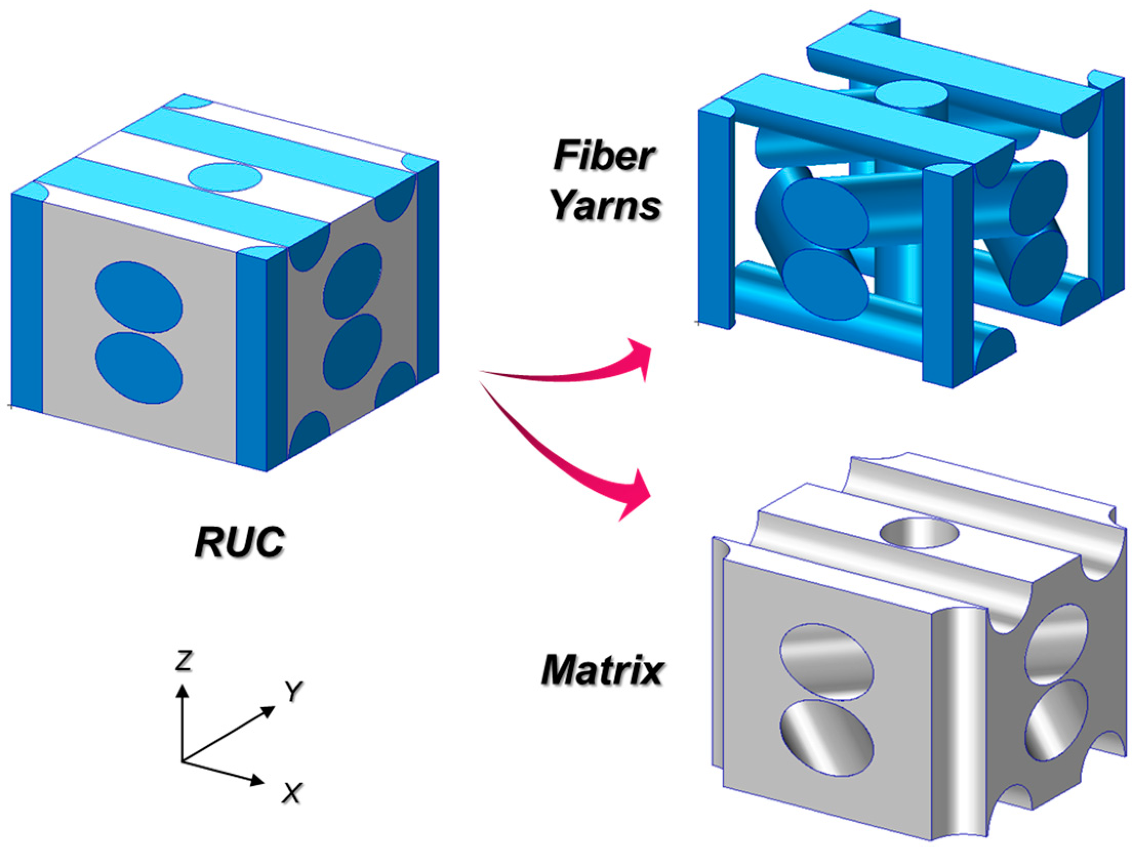
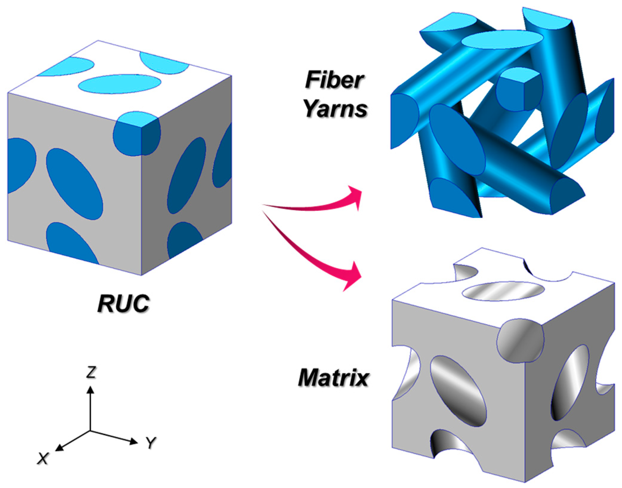
In this paper, three types of carbon/carbon composite materials were considered: 3-D orthogonal type, 4-D in-plane type, and 4-D diagonal type. First, the 3-D orthogonal type has an architecture in which fiber bundles are arranged orthogonally to each other in three directions, as shown in Figure 2. Figure 3 shows the yarn architecture of the 4-D in-plane type. It has a structure in which three different in-plane direction fiber bundles cross each other and the other fiber bundle is arranged in a direction perpendicular to the plane. The 4-D diagonal type has an architecture in which four fiber bundles are crossed in different diagonal directions, as shown in Figure 4.
Carbon/carbon composite materials have different thermo-mechanical characteristics, depending on the type of yarn architectures. First, thermo-mechanical properties may vary depending on the orientation of different fiber bundles for each yarn architecture. In addition, thermo-mechanical properties can be tailored even when manufacturing parameters, such as the diameter of the fiber bundle and the fiber volume fraction, are changed. In this paper, the thermo-mechanical properties of C/C composite materials according to the type of yarn architecture were predicted. In addition, the thermo-mechanical properties according to the change of the fiber volume fraction for each fiber yarn architecture were analyzed.
3. Geometric Model of Repeating Unit Cell (RUC)
Geometric Modelling
Since the yarn architecture of the carbon/carbon composite material has a repeated pattern, the unit cell can be defined as a representative volume element (RVE) or a repeating unit cell (RUC). Figure 5, Figure 6 and Figure 7 shows a geometric model of the RUC in the jamming condition according to the yarn architecture of the carbon/carbon composite material. The jamming condition means that there is no gap between the adjacent fiber bundles.
In the case of 3-D orthogonal and 4-D diagonal type, the dimension of RUC was assumed to be , and the dimension of 4-D in-plane RUC was assumed to be . The fiber bundle diameters inside the RUC were assumed to be the same, and the size of the diameter was determined considering the jamming condition between adjacent fiber bundles. The maximum fiber bundle diameters satisfying the jamming condition for the three types of yarn architecture (3-D orthogonal, 4-D in-plane, 4-D diagonal) are 0.5 mm, 0.25 mm, and 0.354 mm, respectively, and the fiber volume fractions () were 58.9, 41.5, and 68.0%, respectively.
4. Thermo-Mechanical Properties Prediction of C/C Composites
4.1. Effective Stiffness Prediction Method
In this paper, in order to predict the thermo-mechanical properties according to the yarn architecture of carbon/carbon composite materials, the stiffness averaging method based on the iso-strain assumption is applied. This method has been proposed for predicting the effective stiffness of general textile composite materials, and the suitability of the prediction method was verified through comparison with the specimen test in several previous studies [15,22,23,24].
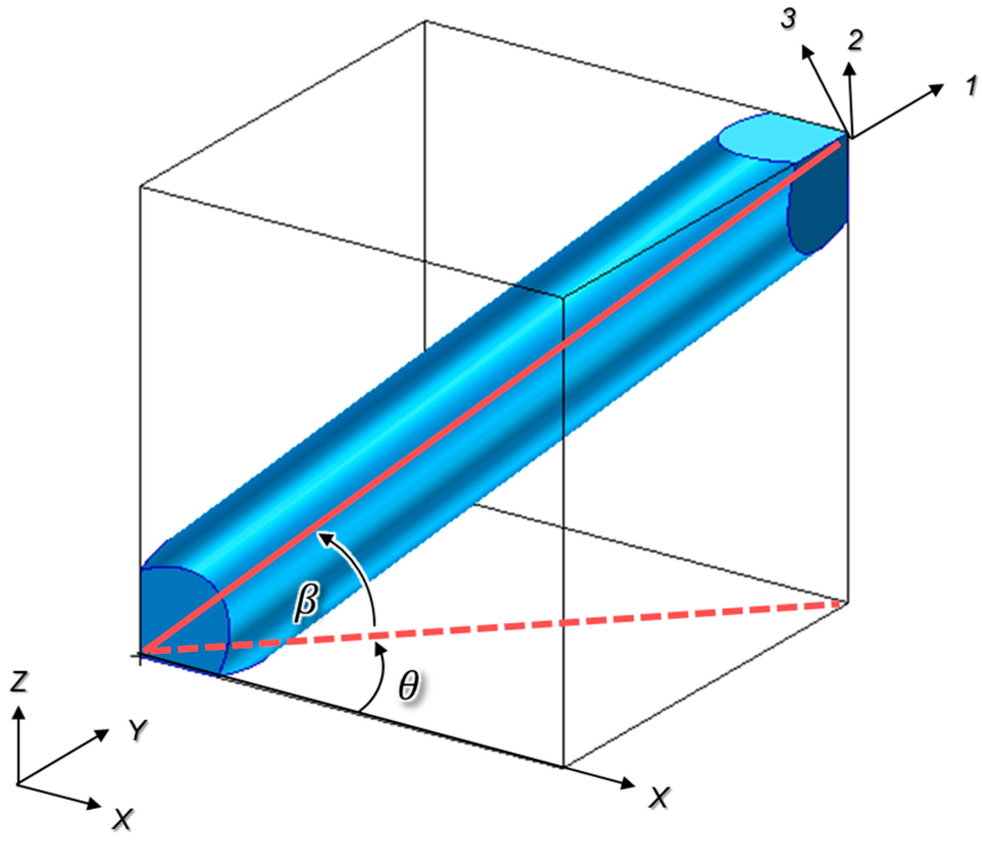
Fiber bundles in the repeating unit cell (RUC) were classified by direction and defined as a total of n fiber bundles. A complete cylindrical yarn was regarded as one fiber bundle, and a local coordinate system (1-2-3), as shown in Figure 8, was applied to indicate the direction of the fiber bundle with respect to the global coordinate system (X-Y-Z). Where means an angle of rotation in the counterclockwise direction with respect to the X-axis within the X-Y plane of the global coordinate system, and means an angle of rotation in the Z-axis direction with respect to the X-Y plane. Table 1 shows geometric parameters of fiber bundles according to the yarn architecture of the carbon/carbon composite material. The fiber bundle ID are defined as Figure 9.
The stress and strain relationship considering the thermo-mechanical properties of the carbon/carbon composite material can be expressed as the following equation based on the effective stiffness determined by the yarn architecture.
where , and mean the average stress, average strain, and average coefficient of thermal expansion (CTE) of the RUC, respectively, and and mean the effective stiffness matrix of the RUC and the ambient temperature change. The average strain of the RUC can be expressed as follows through the iso-strain assumption, which assumes that the fiber bundle and matrix are in a state of uniform strain. In general, the iso-strain assumption tends to evaluate the mechanical properties higher than the iso-stress assumption [19]. If necessary, a weighted average model (WAM) that includes both the iso-stress and iso-strain assumptions can be applied. However, in this paper, the iso-strain assumption was applied to compare and analyze the thermo-mechanical properties according to the yarn architecture of C/C composites under the same conditions.
where means the strain of the mth fiber bundle and matrix with respect to the global coordinate system. The range of index “m” is determined according to the type of yarn architecture of the RUC. In the case of fiber bundles, the index is determined to be the same as the fiber bundle ID defined in Figure 9 and Table 1. In the case of the interstitial matrix, the number next to the highest index of the fiber bundle is determined. For example, the index range of 3-D orthogonal type is m = 1 to 4. Additionally, the indices of the fiber bundle and the interstitial matrix are defined as m = 1 to 3 and m = 4, respectively. The stress and strain of the fiber bundle and matrix in the local coordinate system defined in Figure 9 can be expressed as Equations (3) and (4).
where means a stiffness matrix of the mth fiber bundle and matrix in the local coordinate system and can be obtained through the inverse of compliance matrix . Equation (5) shows the form of the compliance matrix for a 3-D orthotropic material. In the case of a fiber bundle assumed to be a transversely isotropic material, material properties have a relationship of . In addition, in the case of a matrix assumed to be an isotropic material, material properties have a relationship of . means a coordinate transformation matrix of the mth fiber bundle and matrix and is defined as Equations (6) and (7) through and according to the direction of the fiber bundle.
The average stress of the repeating unit cell, can be expressed as Equation (8) based on the stress averaging technique. Here, means the stress in the global coordinate system of the mth fiber bundle, and it can be obtained by transforming the stress in the local coordinate system as in Equation (3) through Equation (9).
where means a volume fraction of mth fiber bundle and matrix. Based on Equations (1)–(9), the effective stiffness matrix and effective thermal expansion coefficient of the RUC can be expressed as Equations (10) and (11). A simple example of the process of calculating the effective stiffness matrix is presented in the Appendix A.
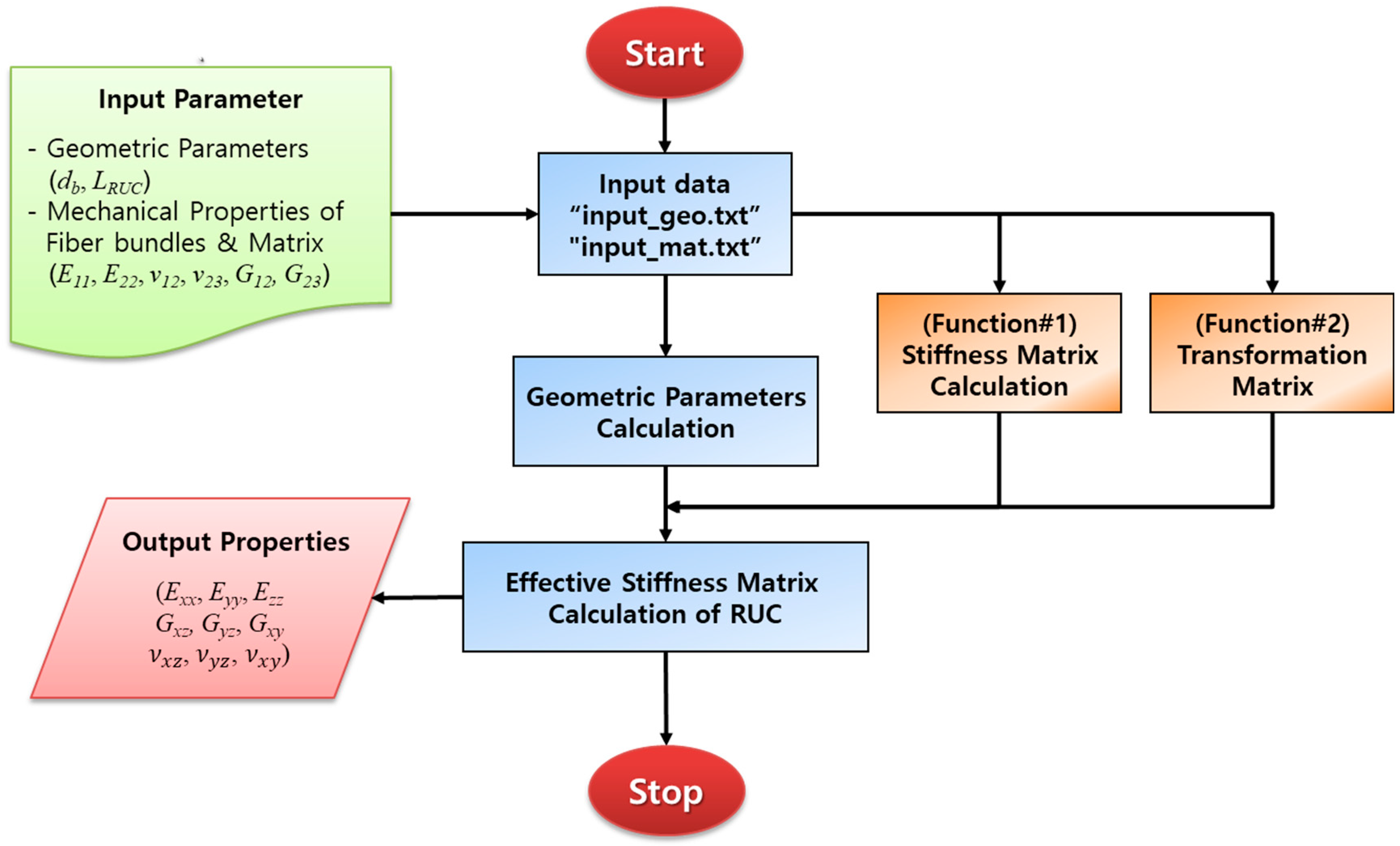
4.2. In-House Code
A MATLAB in-house code was developed based on the method for predicting the effective stiffness and thermal expansion coefficient of the carbon/carbon composite material introduced in Section 4.1. The input parameters are the mechanical properties of the constituent material (fiber and matrix), the dimensions of the RUC according to the yarn architecture, and other geometric parameters, and, based on this, the effective stiffness of the RUC is calculated. From the calculated effective stiffness, the thermo-mechanical properties of the carbon/carbon composite material are output. The flowchart of the in-house code is shown in Figure 10.
In order to verify the in-house code applied in this paper, the effective properties of the 3-D orthogonal C/C composite material were compared with the results obtained by the finite element analysis () [20]. In general, for effective properties prediction through finite element analysis, periodic boundary conditions [21] should be appropriately applied to the finite element model for RUC, and the stress components for each element should be averaged over the RUC volume to calculate the stiffness matrix.
The carbon fiber bundle is assumed to be a transversely isotropic material, such as the unidirectional composites, and the longitudinal direction of the material is defined as direction 1 in the local coordinate system of Figure 8. In addition, the carbon matrix is assumed to be an isotropic material. The material properties of the fiber bundle and matrix at room temperature are given in Table 2 [20,25].
Table 3 shows the comparison between the results of the effective properties of the 3-D orthogonal C/C composite material obtained through the finite element analysis and the prediction results through the in-house code. The shear modulus shows an 18.3% difference compared to the finite element analysis result, but other properties show an error of approximately 4%. Accordingly, it was confirmed that the in-house code applied in the paper was appropriate.
4.3. Thermo-Mechanical Properties Prediction
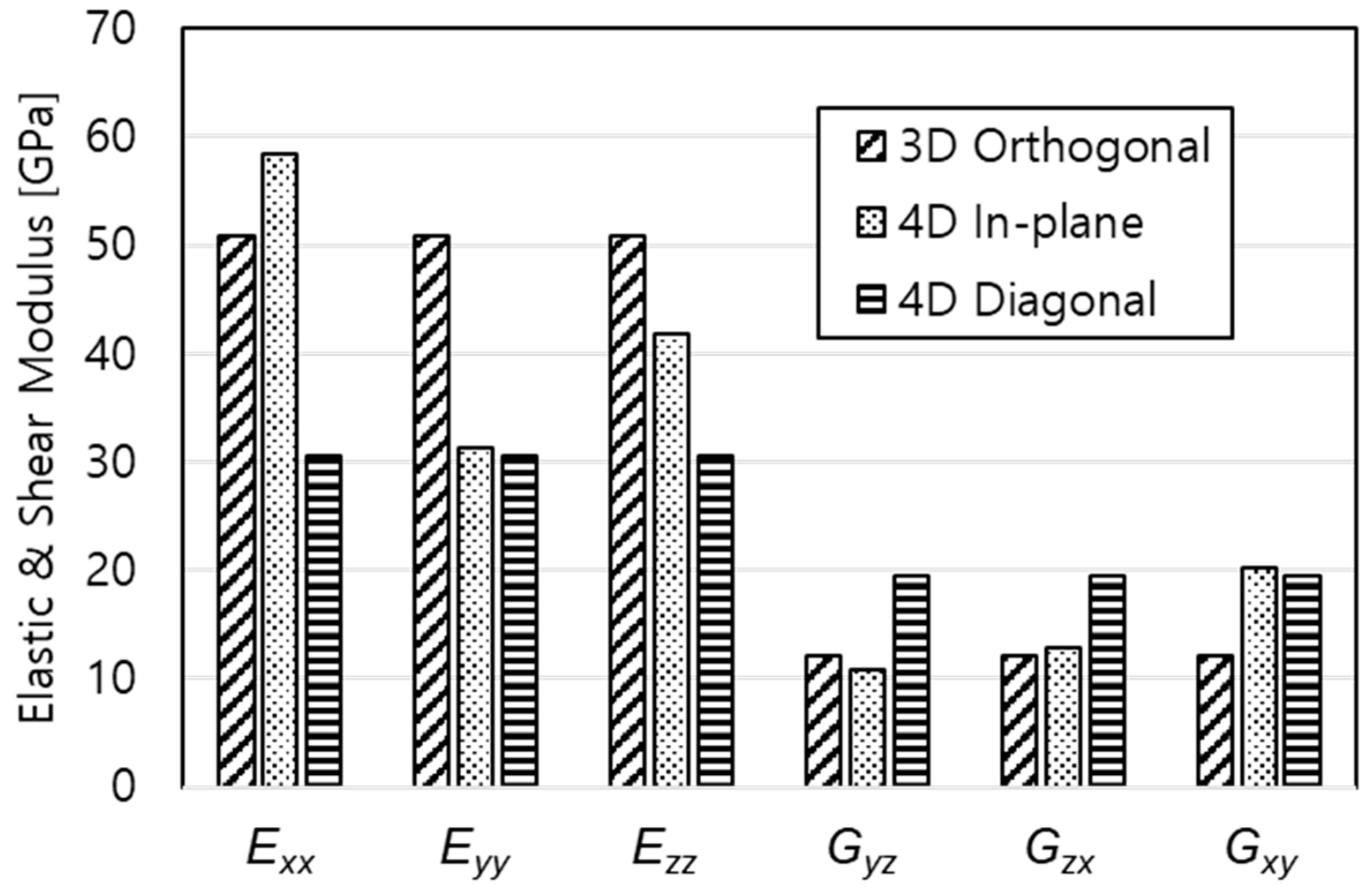
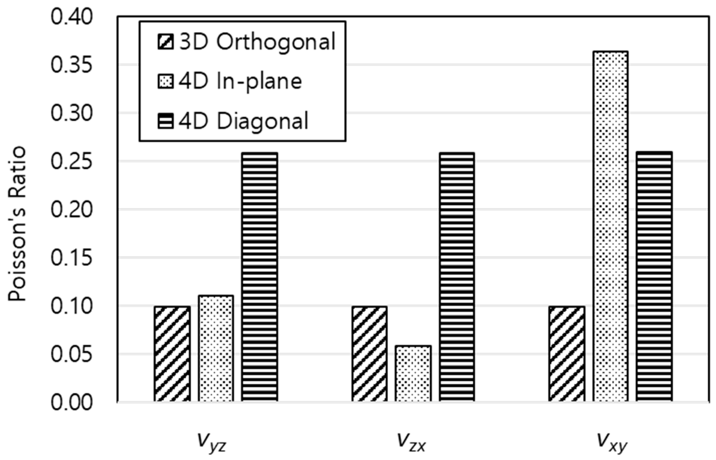
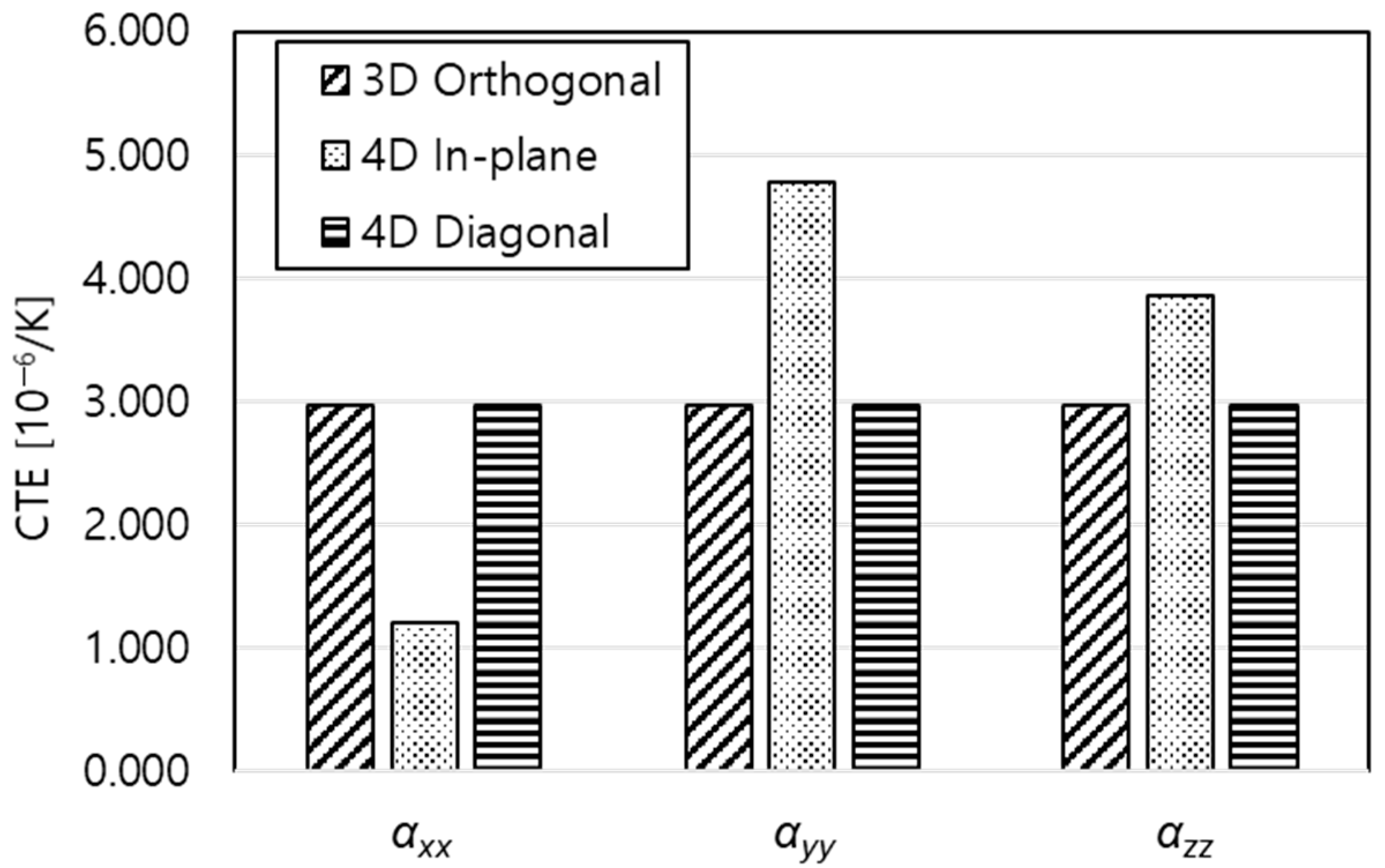
The thermo-mechanical properties were predicted for the three yarn architectures of carbon/carbon composites: 3-D orthogonal, 4-D in-plane, and 4-D diagonal type. First, thermo-mechanical properties according to the yarn architecture were compared under the condition that the fiber volume fraction of the RUC was the same. When the fiber bundle diameters of 3-D orthogonal, 4-D in-plane, and 4-D diagonal type were set to 0.42, 0.25, and 0.28 mm, the fiber volume fraction of the RUC was the same as 41.5%. Table 4 and Figure 11, Figure 12 and Figure 13 show the thermo-mechanical properties of the carbon/carbon composite material according to the yarn architecture with the same fiber volume fraction.
It can be seen that the thermo-mechanical properties of the C/C composite material are determined according to the orientation of the fiber bundle when the fiber volume fraction is the same. In the case of 3-D orthogonal and 4-D diagonal, the elastic modulus and Poisson’s ratio in each direction were the same because the fiber bundle arrangement was uniform about the X, Y, and Z axes. On the other hand, in the case of 4-D in-plane, fiber bundles in a total of three directions are arranged at 120° intervals in the XY plane based on the X-axis, and other fiber bundles are arranged in the Z-axis direction. Therefore, the thermo-mechanical properties in the X, Y, and Z directions were all different. In the case of the elastic modulus, the 4-D in-plane type has the largest Exx, but considering Eyy and Ezz, it can be seen that the 3-D orthogonal type has the best characteristics. In the case of shear modulus and Poisson’s ratio, 4-D diagonal type showed higher values than 3-D orthogonal, and 4-D in-plane type showed the highest values of Gxy and νxy. In the case of coefficient of thermal expansion, the 3-D orthogonal and 4-D diagonal types had almost the same value, and the 4-D in-plane showed different characteristics for each direction.
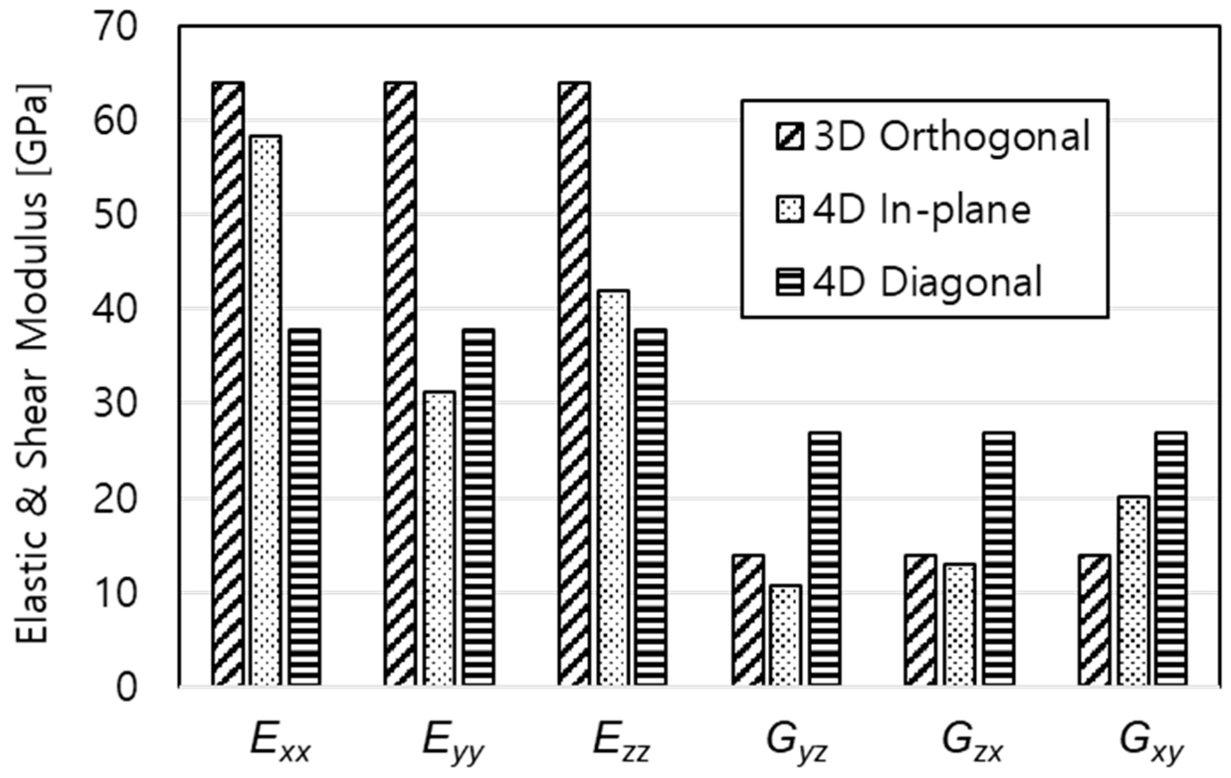
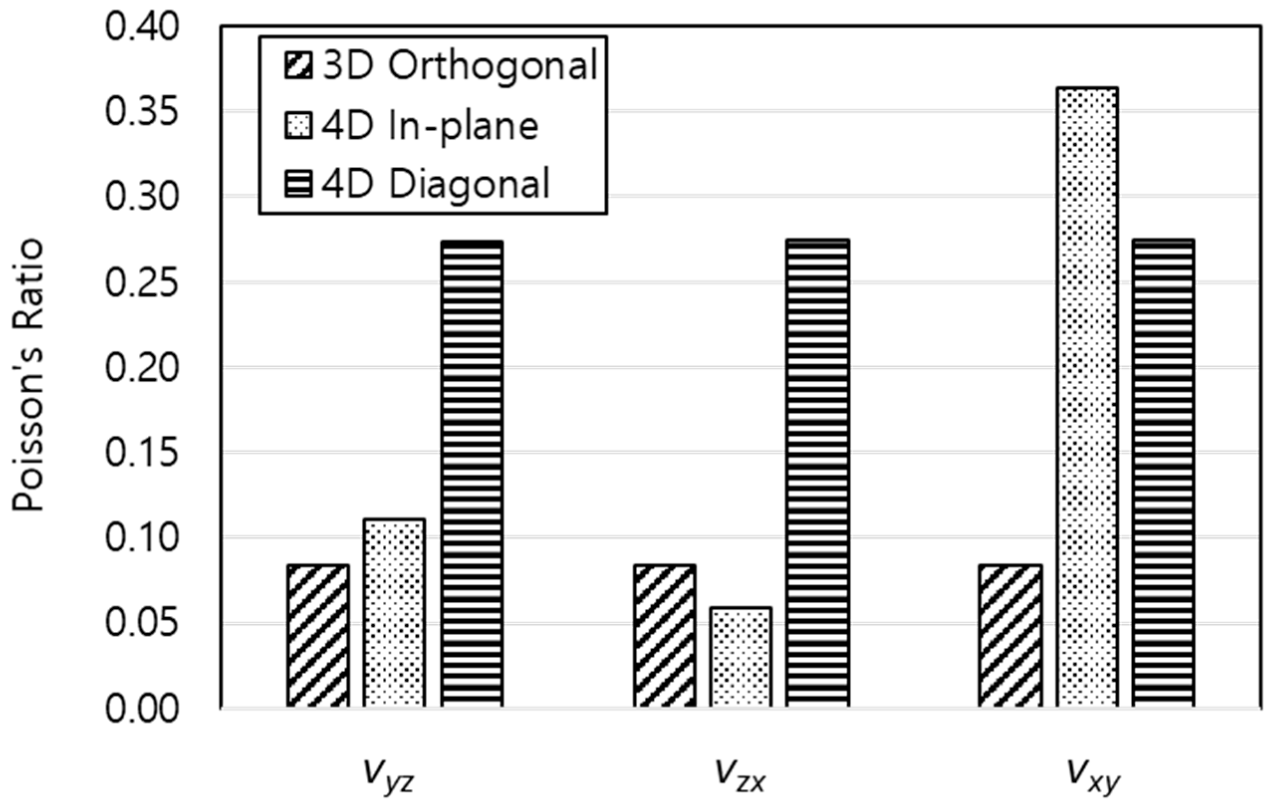
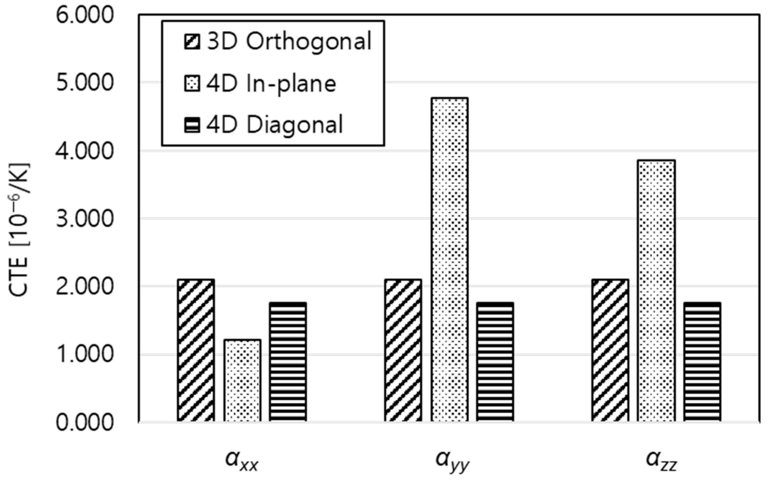
Second, thermo-mechanical properties were compared for the case where the RUC satisfies the jamming condition. In the jamming condition, the fiber bundle diameters of 3-D orthogonal, 4-D in-plane, and 4-D diagonal type were 0.5, 0.25, and 0.354 mm, respectively, and the fiber volume fractions were 58.9, 41.5, and 68.0%, respectively. Table 5 and Figure 14, Figure 15 and Figure 16 show the thermo-mechanical properties of the carbon/carbon composite material according to the yarn architecture in the jamming condition.
It can be seen that thermo-mechanical performance is affected by the different fiber volume fractions of each RUC in the jamming condition. Although thermo-mechanical properties change due to the difference in the maximum fiber volume fraction of the RUC in the jamming condition, the tendency according to the yarn architecture was similar to that when the fiber volume fraction was the same.
Figure 17, Figure 18, Figure 19 and Figure 20 show the thermo-mechanical properties according to the fiber volume fraction for C/C composite materials with three yarn architectures. Each property is shown in the range from 30% to the corresponding maximum fiber volume fraction.
The elastic and shear modulus showed a tendency to increase linearly with the increase of the fiber volume fraction. In the case of 3-D orthogonal type, it showed high performance in elastic modulus compared to other yarn architectures. However, since the shear modulus is relatively low, it can be considered suitable for structures that mainly carry tensile/compressive loads rather than shear loads. In addition, there is an advantage that the range of available fiber volume fraction is relatively wide. In the case of 4-D diagonal type, the performance of the shear modulus was the best, and the range of available fiber volume fraction was widest. In the case of 4-D in-plane, the longitudinal elastic modulus and the in-plane shear modulus show high performance, but the material properties vary depending on the direction, and the range of available fiber volume fraction is small.
The coefficient of thermal expansion decreased slightly nonlinearly as the fiber volume fraction increased. In the case of 3-D orthogonal and 4-D diagonal types, the performance is the same, and since they show homogeneous performance in each direction, it can be seen that they are relatively suitable for structures under high thermal loads.
5. Conclusions
In this paper, the thermo-mechanical properties of carbon/carbon composite materials applied to aerospace structures were predicted, and the characteristics according to the type of yarn architecture and the fiber volume fraction were evaluated. Three yarn architecture of 3-D orthogonal, 4-D in-plane, and 4-D diagonal type were considered, and a geometric model of the repeating unit cell for each yarn architecture was defined. The diameter of the fiber bundle and maximum fiber volume fraction were determined, considering the jamming condition of each repeating unit cell. The effective stiffness was calculated through the stiffness averaging technique by applying the iso-strain assumption to the geometric model of the repeating unit cell, and thermo-mechanical properties, such as elastic and shear modulus, Poisson’s ratio, and coefficient of thermal expansion were predicted for each direction. First, the thermo-mechanical properties of each yarn architecture were compared, when the same fiber volume fraction was applied. Second, the thermo-mechanical properties according to the change of the fiber volume fraction were evaluated for the repeating unit cell in the jamming condition. As in the results of this paper, the thermo-mechanical properties of carbon/carbon composite materials can be tailored according to the type of yarn architecture, the type of constituent materials, and the fiber volume fraction. Therefore, if the material and manufacturing parameters are appropriately selected based on the thermo-mechanical characteristics studied in this paper at the preliminary design stage of aerospace structures, optimal structural performance can be derived.
Author Contributions
Conceptualization, M.K.; methodology, M.K.; software, M.K. and Y.K.; validation, M.K.; formal analysis, M.K.; investigation, M.K.; resources, M.K.; data curation, M.K.; writing—original draft preparation, M.K.; writing—review and editing, M.K. and Y.K.; visualization, M.K.; supervision, M.K.; project administration, M.K.; funding acquisition, M.K. All authors have read and agreed to the published version of the manuscript.
Funding
This work was supported by a National Research Foundation of Korea (NRF) grant funded by the Korean government (MSIT) (No. 2022R1G1A1009460).
Conflicts of Interest
The authors declare no conflict of interest.
Appendix A
A simple example for calculating the effective stiffness matrix of 3-D orthogonal type is as follows. First, according to Figure 9 and Table 1, the stiffness matrix on the local coordinate system of the fiber bundle can be calculated using Equations (A1) and (A2) for m = 1 to 3. The fiber bundle is assumed to be a transversely isotropic material.
Next, the stiffness matrix of the interstitial matrix is defined as Equations (A2) and (A3) for m = 4. The interstitial matrix is assumed to be an isotropic material.
The volume fraction for the mth fiber bundle and matrix can be calculated according to the geometry of the RUC, as shown in Figure 5. Assuming that the overall fiber volume fraction of RUC with the dimension of is 43%, the diameter of the fiber bundle is calculated as 0.4272 mm, and the volume fraction for the mth fiber bundle and interstitial matrix can be calculated as shown in Table A1.

Table A1.
Volume fraction for the mth fiber bundle and matrix.
| m | Constituents | Vm [%] | |
|---|---|---|---|
| 1 | Fiber bundle | 0.139 | 13.9 |
| 2 | Fiber bundle | 0.139 | 13.9 |
| 3 | Fiber bundle | 0.139 | 13.9 |
| 4 | Interstitial Matrix | 0.584 | 58.4 |
| Total | RUC | 1.000 | 100.0 |
In addition, the transformation matrix can be calculated using Equations (6) and (7), according to the direction angles and of each fiber bundle defined in Table 1. Since the matrix is considered as an isotropic material, it is calculated by assuming that the direction angles are, respectively, 0.
Finally, the effective stiffness matrix of RUC can be calculated by substituting the volume fraction of the mth fiber bundle and matrix, the stiffness matrix on the local coordinate system, and the transformation matrix into Equation (10).
References
- Herakovich, C.T. Mechanics of Fibrous Composite; John Wiley & Sons, Inc.: Hoboken, NJ, USA, 1998. [Google Scholar]
- Niu, M.C. Composite Airframe Structures; Conmilit Press Ltd.: Hong Kong, 1992. [Google Scholar]
- Buckley, J.D.; Edie, D.D. Carbon-Carbon Materials and Composites; Noyes Publications: Park Ridge, NJ, USA, 1993. [Google Scholar]
- Devi, G.R.; Rao, K.R. Carbon-Carbon Composites—An Overview. Def. Sci. J. 1993, 43, 369–383. [Google Scholar] [CrossRef]
- Naik, N.K. Woven Fabric Composites; Technomic Publishing Co., Inc.: Lancaster, PA, USA, 1994. [Google Scholar]
- Chou, T.-W.; Ko, F.K. Textile Structural Composites; Elsevier: Amsterdam, The Netherlands, 1989. [Google Scholar]
- Cox, B.N. Handbook of Analytical Methods for Textile Composites; NASA Contractor Report 4750, Contract NAS1-19243; NASA: Washington, DC, USA, 1997.
- Chou, T.-W.; Ishikawa, T. Analysis and Modeling of Two-Dimensional Fabric Composites. In Composite Materials Series 3, Textile Structural Composites; Elsevier Science Publishers: Amsterdam, The Netherlands, 1989; pp. 210–264. [Google Scholar]
- Ko, F.K.; Pastore, C.M.; Lei, C.; Whyte, D.W. A Fabric Geometry Model for 3-D Braid Reinforced FP/AI-Li Composites. In Proceedings of the International SAMPE Metals Conference: Competitive Advances in Metals/Metal Processing, Cherry Hill, NJ, USA, 18–20 August 1987. [Google Scholar]
- Johnson, W.; Masters, J.; O’Brien, T.; Pastore, C.; Gowayed, Y. A Self-Consistent Fabric Geometry Model: Modification and Application of a Fabric Geometry Model to Predict the Elastic Properties of Textile Composites. J. Compos. Technol. Res. 1994, 16, 32–36. [Google Scholar] [CrossRef]
- Ma, C.-L.; Yang, J.-M.; Chou, T.-W. Elastic Stiffness of Three-Dimensional Braided Textile Structural Composites. In Composite Materials: Testing and Design; ASTM STP 893; ASTM: Philadelphia, PA, USA, 1986; pp. 404–421. [Google Scholar]
- Foye, R.L. Finite Element Analysis of the Stiffness of Fabric Reinforced Composites; NASA CR-189597; National Aeronautics and Space Administration: Hampton, VA, USA, 1992.
- Xu, L.; Kim, S.J.; Ong, C.-H.; Ha, S.K. Prediction of material properties of biaxial and triaxial braided textile composites. J. Compos. Mater. 2012, 46, 2255–2270. [Google Scholar] [CrossRef]
- Naik, R.A.; Ifju, P.G.; Masters, J.E. Effect of Fiber Architecture Parameters on Deformation Fields and Elastic Moduli of 2-D Braided Composites. J. Compos. Mater. 1994, 28, 656–681. [Google Scholar] [CrossRef]
- Naik, R.A. Analysis of Woven and Braided Fabric Reinforced Composites; NASA Contractor Report 194930, Contract NAS1-19399; NASA: Washington, DC, USA, 1994.
- Naik, R.A. TEXCAD—Textile Composite Analysis for Design; NASA Contractor Report 4639, Contract NAS1-19708; NASA: Washington, DC, USA, 1994.
- Delneste, L.; Pérez, B. An inelastic finite element model of 4D carbon-carbon composite. AIAA J. 1983, 21, 1143–1149. [Google Scholar] [CrossRef]
- Sharma, R.; Bhagat, A.R.; Mahajan, P. Finite element analysis for mechanical characterization of 4D inplane carbon/carbon composite with imperfect microstructure. Lat. Am. J. Solids Struct. 2014, 11, 170–184. [Google Scholar] [CrossRef]
- Wang, C.; Cao, P.; Tang, M.; Tian, W.; Liu, K.; Liu, B. Study on Properties Prediction and Braiding Optimization of Axial Braided Carbon/Carbon Composite. Materials 2020, 13, 2588. [Google Scholar] [CrossRef] [PubMed]
- Rao, M.V.; Mahajan, P.; Mittal, R. Effect of architecture on mechanical properties of carbon/carbon composites. Compos. Struct. 2008, 83, 131–142. [Google Scholar] [CrossRef]
- Xia, Z.; Zhou, C.; Yong, Q.; Wang, X. On selection of repeated unit cell model and application of unified periodic boundary conditions in micro-mechanical analysis of composites. Int. J. Solids Struct. 2006, 43, 266–278. [Google Scholar] [CrossRef] [Green Version]
- Kim, M.-J.; Park, J.-S. Mechanical Properties Prediction by Geometric Modeling of Plain Weave Composites. J. Korean Soc. Aeronaut. Space Sci. 2016, 44, 941–948. [Google Scholar]
- Kim, M.J. Mechanical Properties Prediction by Manufacturing Parameters for Braided Composites. J. Aerosp. Syst. Eng. 2020, 14, 26–32. [Google Scholar]
- Kim, M.; Park, J. Stiffness Prediction of Triaxial Braided Composites Accounting for Manufacturing Parameters. Int. J. Aeronaut. Space Sci. 2021, 22, 602–612. [Google Scholar] [CrossRef]
- Liao, X.; Li, H.; Xu, W.; Li, K. Study on the thermal expansion properties of C/C composites. J. Mater. Sci. 2007, 42, 3435–3439. [Google Scholar] [CrossRef]
Figure 1.
Multiformity of carbon/carbon composite materials.

Figure 2.
Yarn architecture of 3-D orthogonal C/C composites.

Figure 3.
Yarn architecture of 4-D in-plane C/C composites.

Figure 4.
Yarn architecture of 4-D diagonal C/C composites.

Figure 5.
RUC of 3-D orthogonal C/C composites in jamming condition.

Figure 6.
RUC of 4-D in-plane C/C composites in jamming condition.

Figure 7.
RUC of 4-D diagonal C/C composites in jamming condition.

Figure 8.
Coordinate systems of the fiber bundle in RUC.

Figure 9.
Fiber bundle ID according to yarn architectures.

Figure 10.
Flowchart of the in-house code.

Figure 11.
Elastic and shear modulus of C/C composites ().

Figure 12.
Poisson’s ratio of C/C composites ().

Figure 13.
Coefficient of thermal expansion of C/C composites ().

Figure 14.
Elastic and shear modulus of C/C composites in jamming condition.

Figure 15.
Poisson’s ratio of C/C composites in jamming condition.

Figure 16.
Coefficient of thermal expansion of C/C composites in jamming condition.

Figure 17.
Elastic modulus of C/C composites for fiber volume fraction.

Figure 18.
Poisson’s ratio of C/C composites for fiber volume fraction.

Figure 19.
Shear Modulus of C/C composites for fiber volume fraction.

Figure 20.
CTE of C/C composites for fiber volume fraction.

Table 1.
Geometric Parameters according to Yarn Architectures of C/C Composite.
| Yarn Architecture | Fiber Bundle ID | Complete Yarn Count | Length [mm] | [deg] | [deg] |
|---|---|---|---|---|---|
| 3-D Orthogonal | 1 | 1 | 1.000 | 0 | 0 |
| 2 | 1 | 1.000 | 90 | 0 | |
| 3 | 1 | 1.000 | 0 | 90 | |
| 4-D In-plane | 1 | 2 | 1.000 | 0 | 0 |
| 2 | 2 | 0.707 | 45 | 0 | |
| 3 | 2 | 0.707 | −45 | 0 | |
| 4 | 2 | 0.750 | 0 | 90 | |
| 4-D Diagonal | 1 | 1 | 1.732 | 45 | 35.3 |
| 2 | 2 | 0.866 | 135 | 35.3 | |
| 3 | 2 | 0.866 | 225 | 35.3 | |
| 4 | 2 | 0.866 | 315 | 35.3 |
| Property | Constituents | |
|---|---|---|
| Carbon Fiber Bundle | Carbon Matrix | |
| E11 [MPa] | 240,900 | 19,000 |
| E22 [MPa] | 19,000 | 19,000 |
| E33 [MPa] | 19,000 | 19,000 |
| ν23 | 0.34 | 0.2 |
| ν31 | 0.20 | 0.2 |
| ν12 | 0.20 | 0.2 |
| G23 [MPa] | 7060 | 7917 |
| G31 [MPa] | 23,630 | 7917 |
| G12 [MPa] | 23,630 | 7917 |
| α11 [10−6/K] | −0.84 | 8 |
| α22 [10−6/K] | 7.2 | 1.8 |
| α33 [10−6/K] | 7.2 | 1.8 |
Table 3.
Comparison of effective properties of 3-D orthogonal C/C composites ( ).
| Property | FEM [20] | In-House Code | Difference |
|---|---|---|---|
| Exx [GPa] | 54.32 | 51.97 | −4.3% |
| Eyy [GPa] | 54.32 | 51.97 | −4.3% |
| Ezz [GPa] | 54.32 | 51.97 | −4.3% |
| νyz | 0.094 | 0.10 | +3.8% |
| νzx | 0.094 | 0.10 | +3.8% |
| νxy | 0.094 | 0.10 | +3.8% |
| Gyz [GPa] | 10.40 | 12.30 | +18.3% |
| Gzx [GPa] | 10.40 | 12.30 | +18.3% |
| Gxy [GPa] | 10.40 | 12.30 | +18.3% |
Table 4.
Thermo-mechanical properties of C/C composite material ( ).
| Property | Yarn Architecture | ||
|---|---|---|---|
| 3-D Orthogonal | 4-D In-Plane | 4-D Diagonal | |
| Exx [MPa] | 50,890 | 58,313 | 30,569 |
| Eyy [MPa] | 50,890 | 31,306 | 30,569 |
| Ezz [MPa] | 50,890 | 41,880 | 30,576 |
| νyz | 0.10 | 0.11 | 0.26 |
| νzx | 0.10 | 0.06 | 0.26 |
| νxy | 0.10 | 0.36 | 0.26 |
| Gyz [MPa] | 12,152 | 10,722 | 19,450 |
| Gzx [MPa] | 12,152 | 12,891 | 19,450 |
| Gxy [MPa] | 12,152 | 20,143 | 19,454 |
| αxx [10−6/K] | 2.961 | 1.205 | 2.968 |
| αyy [10−6/K] | 2.961 | 4.774 | 2.968 |
| αzz [10−6/K] | 2.961 | 3.862 | 2.968 |
Table 5.
Thermo-mechanical properties of C/C composite material in jamming condition.
| Property | Yarn Architecture | ||
|---|---|---|---|
| 3-D Orthogonal (Vf = 58.9%) | 4-D In-Plane (Vf = 41.5%) | 4-D Diagonal (Vf = 68.0%) | |
| Exx [MPa] | 63,937 | 58,313 | 37,837 |
| Eyy [MPa] | 63,937 | 31,306 | 37,837 |
| Ezz [MPa] | 63,937 | 41,880 | 37,848 |
| νyz | 0.08 | 0.11 | 0.27 |
| νzx | 0.08 | 0.06 | 0.27 |
| νxy | 0.08 | 0.36 | 0.27 |
| Gyz [MPa] | 13,919 | 10,722 | 26,842 |
| Gzx [MPa] | 13,919 | 12,891 | 26,842 |
| Gxy [MPa] | 13,919 | 20,143 | 26,848 |
| αxx [10−6/K] | 2.094 | 1.205 | 1.748 |
| αyy [10−6/K] | 2.094 | 4.774 | 1.748 |
| αzz [10−6/K] | 2.094 | 3.862 | 1.748 |
Publisher’s Note: MDPI stays neutral with regard to jurisdictional claims in published maps and institutional affiliations. |
© 2022 by the authors. Licensee MDPI, Basel, Switzerland. This article is an open access article distributed under the terms and conditions of the Creative Commons Attribution (CC BY) license (https://creativecommons.org/licenses/by/4.0/).
Share and Cite
MDPI and ACS Style
Kim, M.; Kim, Y. A Thermo-Mechanical Properties Evaluation of Multi-Directional Carbon/Carbon Composite Materials in Aerospace Applications. Aerospace 2022, 9, 461. https://doi.org/10.3390/aerospace9080461
AMA Style
Kim M, Kim Y. A Thermo-Mechanical Properties Evaluation of Multi-Directional Carbon/Carbon Composite Materials in Aerospace Applications. Aerospace. 2022; 9(8):461. https://doi.org/10.3390/aerospace9080461
Chicago/Turabian StyleKim, Myungjun, and Yongha Kim. 2022. "A Thermo-Mechanical Properties Evaluation of Multi-Directional Carbon/Carbon Composite Materials in Aerospace Applications" Aerospace 9, no. 8: 461. https://doi.org/10.3390/aerospace9080461
Note that from the first issue of 2016, this journal uses article numbers instead of page numbers. See further details here.