1. Introduction
The steadily accelerating growth of the space industry and its peripheral sectors is a phenomenon that has recently been noticed and reported by numerous independent observers [
1,
2]. Several factors contribute to the sector expansion, including, but not limited to, a gradually occurring shift in national space policies, decreasing launch costs [
3], and improving satellite payload capabilities. As a result of those factors, the dawn of the XXI century has seen the rapid emergence and strengthening of the small satellite market. Although, today, the position of nanosatellite and microsatellite platforms is already firmly established within the space sector, a new trend is seen—in order to enhance the operational capabilities of their platforms, the small satellite integrators are seeking dedicated mobility solutions [
4].
In the context of chemical propulsion systems, the increased demand for dedicated small satellite mobility solutions, coupled with the REACH regulation concerns over the toxicity of the traditional hydrazine (N2H4) propellant [
5], has provided an additional incentive for a non-toxic (also referred to as “green”) propellant search. Within the frame of the EU-funded Green Advanced Space Propulsion (GRASP) FP7 project alone, ninety-eight green propellant candidates were considered [
6]. However, there are a few notable green propellant alternatives that, in recent decades, have been seriously considered as monopropellant hydrazine replacements. Those can be classified into three major categories: Energetic Ionic Liquids (EILs), Liquid NOx Monopropellants, and Hydrogen Peroxide Aqueous Solutions (HPAS) [
7]. The propellants that fall into the first class, EILs, have received a lot of attention both from academia and the industry. Among others, those include: hydroxylammonium nitrate (HAN)-based propellants [
8,
9] such as AF-M315E, which has already been in-space demonstrated during the GPIM (Green Propellant Infusion Mission) mission [
10,
11] and is proposed for the commercial line of CubeSat Modular Propulsion Systems (MPS) [
12], as well as ammonium dinitramide (ADN)-based propellants [
13,
14] such as LMP-103S, which has already been in-space demonstrated during the PRISMA (Prototype Research Instruments and Space Mission Technology Advancement) mission [
15,
16] and is offered for the commercial microsatellite propulsion modules [
17]. The hydrazine replacements that fall within the second category of non-toxic propellants, Liquid NOx Monopropellants, include, among others, Nitrous Oxide Fuel Blends (NOFBs) [
18,
19]. Those have also been already flown propelling Commercial-Off-The-Shelf (COTS) CubeSat propulsion systems [
20]. The third category of green propellants, HPAS, includes a plethora of Hydrogen Peroxide (H
2O
2) water-based solutions, classified according to their concentration (H
2O
2 concentration) and type [
21]. For spacecraft propulsion applications, the >85% (weight concentration) Hydrogen Peroxide, also referred to as High-Test Peroxide (HTP), is typically used [
22].
All three categories of non-toxic propellants presented above have different sets of properties that impact not only propulsion system performance but also its operational, functional, safety, and cost characteristics. In the literature, an array of green propellant trade-off studies has been published [
5,
6,
7]. In [
23], the prospective hydrazine replacements have been compared against metrics that include basic performance, materials compatibility, operational storage temperature range, absolute toxicity, vapor pressure, plume constituents, and others. In light of those evaluation criteria, HTP has long been considered as a promising non-toxic spacecraft propellant, mainly due to its low toxicity, non-carcinogenic nature, environmentally benign decomposition products, low cost, low decomposition temperature, and high-density specific impulse [
24,
25,
26]. At the Ł-IoA, the benefits of using HTP for space propulsion systems have been recognized as early as in 2007 [
27]. Since then, a significant in-house research effort focused on developing the HTP propellant technology has been undertaken at the Ł-IoA [
28]. Among others, the research included the European Space Agency (ESA) and domestically funded research activities in the areas of patented HTP production technology, HTP catalytic decomposition and catalyst production, and HTP bipropellant operation and hypergolic ignition [
29]. Apart from investigating the fundamental HTP chemistry and its decomposition mechanisms, the Ł-IoA is active in numerous research programs targeting the development of rocket and satellite propulsion experimental hardware. Those include the ILR-33 AMBER suborbital rocket utilizing an HTP hybrid rocket propulsion, reaction control system utilizing HTP, Green Liquid Bipropellant Rocket Engine (GRACE), and Throttleable Liquid Propulsion Demonstrator (TLPD).
The expertise gathered over decade-long research and engineering studies related to the usage of HTP as a rocket and spacecraft propellant paved the path toward putting HTP on the Ł-IoA roadmap as a viable non-toxic spacecraft propellant alternative. More specifically, its properties such as a high-density, high specific impulse, low toxicity, and low production cost, made it a very attractive option for a propellant that could satisfy the needs of small satellite integrators. As a result, highly concentrated (>98% weight concentration) hydrogen peroxide was selected as the propellant for POLON—the first complete satellite propulsion system developed at the Ł-IoA.
2. Propulsion Module Architecture
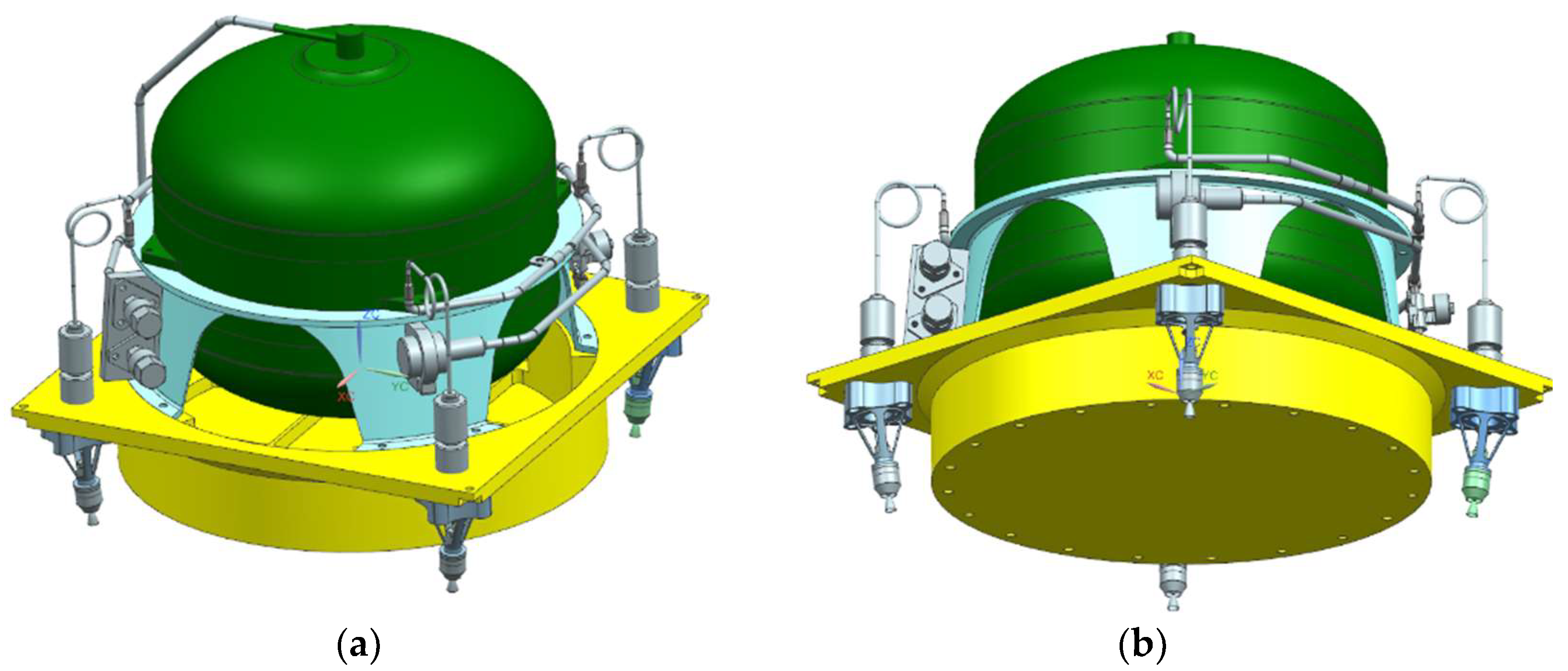
POLON is a green propellant propulsion module intended to provide mobility capabilities to microsatellite class platforms. The module is devised to provide propulsion to Earth-orbiting platforms for which the total mass does not exceed 200 kg. It is planned that, for a typical microsatellite mission, the module will support orbital maneuvers, including an altitude change maneuver, inclination change maneuver, orbital phasing, station keeping, debris avoidance, and a deorbiting maneuver. The POLON propulsion module physical layout is shown in
Figure 1.
The fluidic subsystem architecture of POLON is based around a single propellant tank, four monopropellant thruster arrangement. The fluidic subsystem utilizes blowdown pressurization by helium, whereas the pressurizing gas is contained within a diaphragm propellant tank. The propellant tank, which is designed for the nominal blowdown ratio of 4:1, can contain 9.6 liters of usable propellant. In order to satisfy the range safety regulations, the propellant tank outlet is isolated from each thruster inlet with three independent inhibits: one subsystem-level bistable latch valve and one component-level monostable two-seat flow control valve. Each monopropellant thruster utilized by POLON is designed for the nominal thrust of 1N.
The physical layout of POLON is shown in
Figure 1. In the figure, the fluidic sub-system is shown together with a bottom structural panel of a microsatellite platform whose list of target mission profiles could be significantly enhanced by equipping it with propulsion system.
3. Technology Development Materials and Methods
While extensive expertise with HTP chemistry and HTP liquid propulsion components has been developed at Ł-IoA during numerous research programs, additional targeted research efforts were needed in order to enable development of a complete satellite propulsion module. The technology development activities that were undertaken within the frame of POLON are summarized in the following subsection and described in detail in the subsections that follow.
3.1. Summary of the Key Development Tasks
The key development tasks that have to be tackled in order to enable development of POLON encompass design, analysis, and test activities. First of all, development of dedicated liquid propulsion performance prediction models, utilizing HTP as a flow medium, is needed for propulsion system sizing and propulsion performance assessment during different phases of the mission. The analytical performance assessment goes hand-in-hand with verification of steady-state and transient hydraulic phenomena on a dedicated test rig. Apart from the investigation of the fluidic subsystem behavior, significant research effort is dedicated to the development of individual fluidic components. Those include catalyst bed development, monopropellant thruster design, and hot-fire testing, as well as propellant tank development (including elastomeric diaphragm development). Last but not least, engineering work is dedicated to the design of ground support equipment (GSE), specifically focusing on the development of HTP propellant loading equipment, architected to allow for conducting safe and efficient propellant and pressurant loading operations under launch range safety conditions. More details on the key development tasks, as well as their specific objectives, are given in
Table 1. The table also lists the primary types of methods that were utilized by each development task (laboratory work, test campaign, analysis, etc.). It must be noted that the list of the development tasks provided in
Table 1 is not exhaustive.
3.2. Computational Performance Assessment
One of the first steps that was performed within the frame of the project was kick-off of an ongoing development activity aimed at developing computational performance models of a complete propulsion system. First of all, POLON baseline design assessment was performed, based on the trade-off studies and market research completed at the beginning of the project. Next, based on the chosen configuration, its performance was assessed. As those analyses were needed at the very preliminary state of the project, the computational simulations proved useful.
General architecture of proposed propulsion module configuration was recreated in Matlab SIMULINK environment. The software was chosen mostly by its versatility—it allows to connect different domains (such as fluidic, thermal, and control) in one concise simulation model. Matlab also proved useful in terms of rapid prototyping of simulations.
The propulsion subsystems are mostly simulated and analyzed in more specialized software, such as EcosimPro software with ESPSS (European Space Propulsion System Simulation) toolkit (e.g., [
30,
31]). In the next stages of POLON development, EcoSim ESPSS software will be utilized for propulsion performance assessment, as it should yield more precise results due to the higher sophistication of simulations environment.
3.2.1. Steady-State and Transient Performance
For steady-state and transient performance analyses, two different branches of simulation models were developed. Such approach was chosen as some of the numerical components from SIMULINK libraries have limitations in certain boundary conditions (such as low pressure).
Steady-state analyses included determining impact of system pressure, temperature, component geometry (e.g., orifice diameter), and number of simultaneously operating thrusters over the resulting thrust values and general behavior of the system. Transient simulations focused on studying selected phenomena, mostly including Minimum Impulse Bit (MIB) analyses and waterhammer (hydraulic shock) studies. MIB simulations were used in order to assess variation of impulse bit values with regard to the system pressure and impulse durations. Waterhammer analyses were used to determine occurrence of the pressure peaks during various events of short duration (such as valves opening).
3.2.2. Loading and Pressurization Performance
In order to facilitate sizing of GSE components used for propellant loading, additional Matlab simulation model was created. The model features greatly simplified construction limited to: POLON tank, HTP source (reservoir), pump, pressurant (helium gas) source (gas cylinder), mechanical gas regulator, and isolation valve between gas regulator and tank. As a result, mass/volume flow rate of the pump and regulator flow coefficient (Cv) could be assessed and later used for choosing the exact baseline hardware from pre-selected component list.
The model was designed in a way so that two processes—propellant loading and gas pressurization—could be isolated, i.e., changing one process parameters would not impact the second one. Additionally, simple proportional regulator was used in order to control the pump flow rate.
3.3. Experimental Fluidic Performance Verification
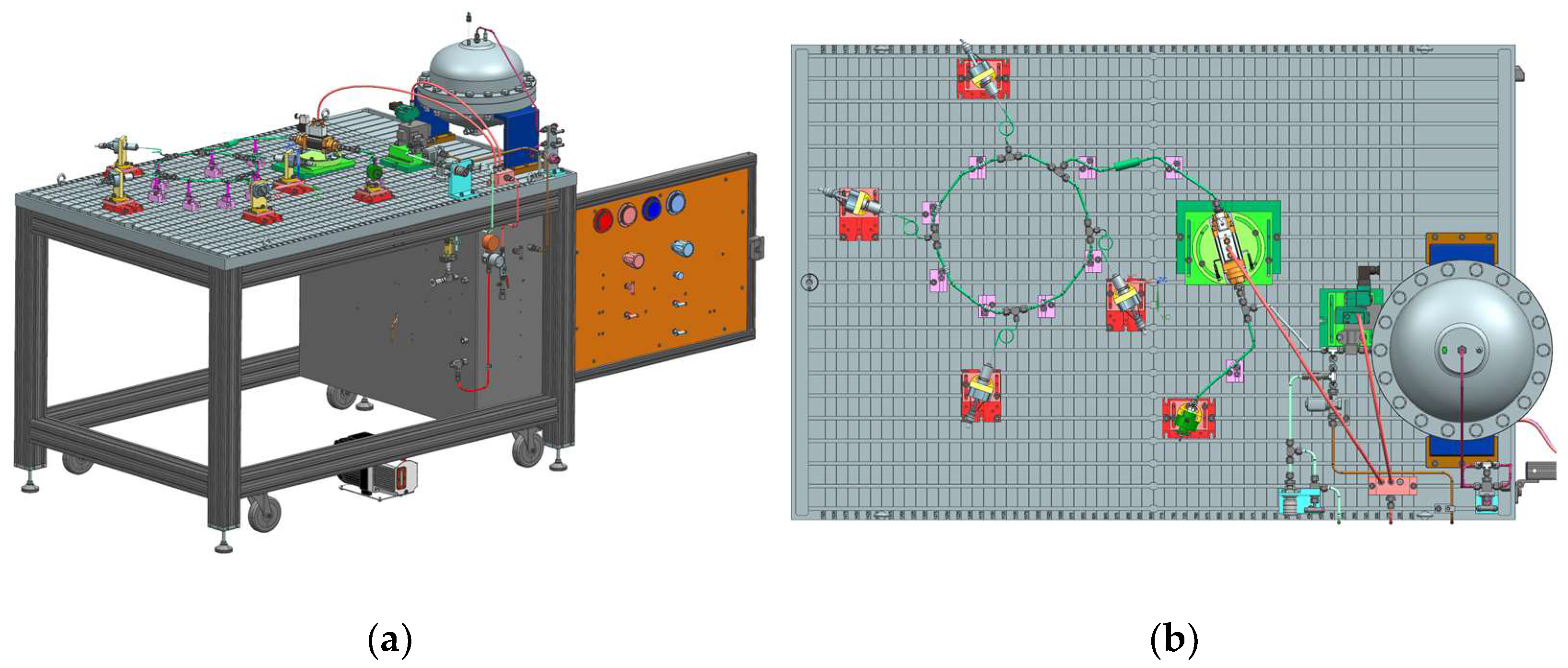
Concurrently to the development of computational performance models, intended to facilitate propulsion system sizing, the fluidic subsystem design process is supported with a series of experimental test rigs. The test rig, which is central to POLON fluidic subsystem design process, as it aims to characterize the fluidic subsystem in terms of steady-state and transient hydraulic phenomena, is shown in
Figure 2. The test setup, also referred to as fluidic breadboard, is an accurate representation of POLON fluidic subsystem. In order to mitigate the influence of gravity, the fluidic breadboard is a flattened, 2D representation of the actual 3D POLON fluidic subsystem geometrical layout. All POLON tube radii and tube lengths are preserved in the fluidic breadboard. In addition, the test rig aims to make use of flight-like components as much as possible. In particular, this applies to the following hardware: (I) tube size and material, (II) tube fittings, (III) tank internal geometry and configuration, and (IV) other valves. In addition, the test rig is reconfigurable, so it allows to investigate the effects of fluidic subsystem design changes on the hydraulic phenomena.
The main fluidic breadboard requirements, dictated by the experiment objectives, are listed in
Table 2. Of particular interest is the system transient response following priming. As line venting is considered to prolong the system lifetime, the fluidic subsystem shall be qualified for multiple priming events. As one of the experiment objectives is to investigate the impact of saturation level, during the experiments, the time of exposure of the propellant to the high-pressure pressurizing gas (which could impact the saturation level) is planned to be controlled. In addition, the experiments are to be repeated, and the dispersion in the valve opening times will be accounted for. This will be needed especially because the test runs are planned to be conducted on different days, and hence under different temperature conditions. Temperature conditions could impact the characteristics of the valve opening times due to the behavior of sealing materials used. During tests, apart from the valve opening time, the following factors affecting hydraulic phenomena will be considered: (I) tubing internal diameter, (II) tubing layout (number of branches, bends, individual tube lengths), (III) vapor pressure of the propellant, (IV) saturation level.
3.4. Catalyst Bed Development
Apart from the system-level propulsion design and analysis activities, POLON incorporates development of individual propulsion components and technologies. One of the key technologies under assessment is the catalyst bed, which is a critical component of every monopropellant thruster. The catalyst bed should be optimized to provide the best possible compromise among lifetime, response time, size, and weight. The cost is another driving factor. However, in case of 1 N thruster and the required amount of a catalyst, it remains a minor concern.
Chemical stabilizers, added to hydrogen peroxide to sustain its concentration for a space mission duration, may affect the catalyst lifetime. This problem does not exist in case of propellant grade hydrazine. Therefore, selection of the catalyst for hydrogen peroxide must take into consideration the actual content of the propellant (e.g., peroxide containing stabilizing phosphates affects lifetime of manganese oxide catalyst [
32,
33]). Other relevant properties of catalysts include mechanical strength and thermal resistance.
Anhydrous hydrazine can be successfully decomposed by iridium catalysts. Shell-405 [
34] and KC-12-GA are robust catalysts, applied in most of the hydrazine thrusters. For hydrogen peroxide, up to 90%, silver wire mesh and silver-coated nickel screens have been widely used [
35]. Pure silver has limited application to the highest-grade HTP because of the fact that the melting point of silver (960 °C) is close to the adiabatic decomposition temperature of 98% peroxide (940 °C). The equivalent of Shell-405, as a workhorse, baseline catalyst for 98% HTP, has never been developed. Therefore, propulsion technologies for the highest grade of hydrogen peroxide (98–99%) are still being the subject of research.
Hydrogen peroxide decomposes exothermically into steam and oxygen. Formula (1) presents the equation, including substrate and final products. Decomposition products, containing oxygen, up to 46% by weight, at temperature exceeding 940 °C create strongly oxidative conditions, different from those generated by decomposition of hydrazine. Therefore, selection of support and active phase for HTP decomposition catalyst must be driven not only by screening of catalytically active materials (often performed with low concentration of hydrogen peroxide) but also considering their high-temperature oxidation resistance.
Numerous studies have been performed with HTP catalysts [
36]. Ceramic-supported manganese oxides have been identified as a promising candidate for limited-lifetime usage. Platinum, on the other hand, very active with hydrogen peroxide, has potential for long lifetime. According to Romeo et al., platinum outperforms even pure silver [
37].
For the purpose of the current activity, aiming at development of 1 N thruster, the number of substrate-active phase compositions have been prepared. Manganese oxides (see
Figure 3) and platinum supported on ceramics and metal are the subject of screening. A different (from numerous presented research activities, e.g., [
32,
36,
38]) technique of screening is planned to be applied. A thruster-like catalytic chamber will serve for the test setup, as only this research method will provide reliable data concerning evolution of a catalyst performance with regard to the run time and simulated real-like operating conditions. Moreover, with a strong support of advanced modeling, this experimental approach will help to design the optimized catalyst bed geometry.
3.5. Monopropellant Thruster Development
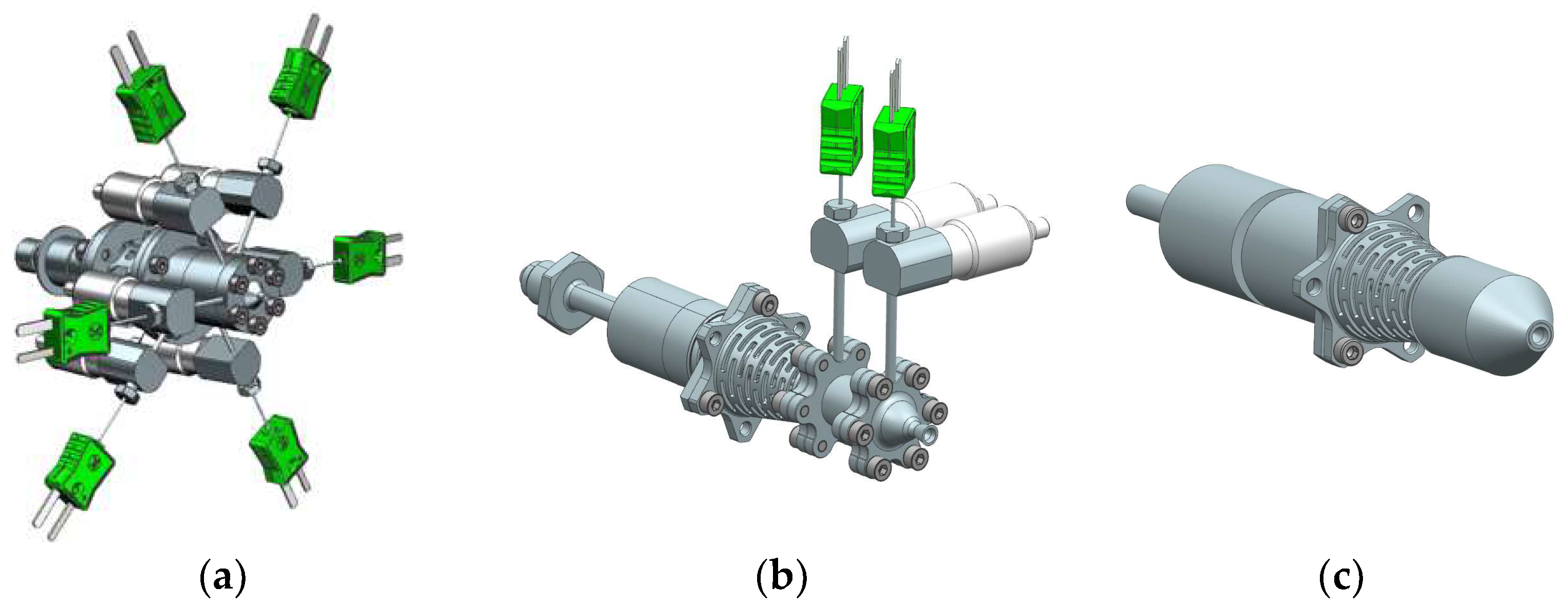
Development of thruster for POLON is based on a test campaign that includes a series of different models, which are listed in
Table 3, and schematically shown in
Figure 4. For initial testing, thruster with disassembled injector face was used. Pressure and temperature were measured at five points (axially spaced every 3 mm) in the decomposition chamber and one in the injector. Dribble volumes are much higher than in the planned qualification model; however, this model is not used to compare the catalyst activity. Instead, it is used to compare catalyst lifetime for 1 kg of 98% hydrogen peroxide throughput. Initial prototype model testing aims to fix decomposition chamber length, catalyst bed type, and injector type.
A prototype model was developed for environmental testing in the vacuum chamber. The main goals for the vacuum testing are to validate thrust level for low ambient pressures and to choose the optimal Ae/At (nozzle area ratio). Hydrogen peroxide decomposes to oxygen and steam. The decreasing temperature on the divergent section of the nozzle can cause condensation of water vapor if the Ae/At ratio is too high. This phenomenon can cause separation of the flow from the nozzle and can cause a significant decrease in performance. Three nozzles with different Ae/At ratios were used to avoid that. Moreover, the prototype model has lower dribble volume than the initial prototype model. That change will allow decreasing rise time and decay time—critical characteristics of the pulse-mode operation for a thruster.
The breadboard model is similar to the prototype model. The main difference is a change of material for hot-operating elements, where stainless steel will be replaced by Inconel 718. Four breadboard model thrusters will be tested on the fluidic breadboard test stand to check pressure change and possible pressure instabilities occurring during multiple thruster operation. Another parameter analyzed by Ł-IoA will be the waterhammer and its influence on the pulse-mode operation.
The qualification thruster will be manufactured in the final configuration (qualification and engineering models), where each component will be electron beam welded (EBW). Only the valve will be disassembled from the thruster body. A high-level requirement in qualification tests is to prove the high thruster performance for 6 kg of the propellant throughput. The catalyst bed will be welded inside the thruster. The condition of the catalyst bed after hot-fire testing will be checked by a computerized tomography (CT) scan. Furthermore, catalyst mass loss will be checked between different test runs. Qualification tests should be a reflection of a mission. A typical mission for AOCS, as in this case, consists of steady-state and pulse-mode operation. Qualification tests are planned for about 30 000 pulses and more than 3 h of firing time.
3.6. Material Compatibility
For satellite propulsion systems, such as POLON, intended for in-orbit missions lasting from several months to several years, long-term propellant storage is one of the most critical capabilities. Unfortunately, from the historical perspective, HTP has been widely recognized as problematic in terms of long-term storage [
39]. In the past century, this issue has led to HTP losing ground to hydrazine and slowly becoming less and less relevant as a space propellant. However, recent advantages in purification and stabilization of concentrated hydrogen peroxide have resulted in rediscovery of its propulsive potential [
24]. Currently available purity classes of HTP are believed to be capable of serving in missions of multiple years without excessive decomposition [
40]. Despite that, ambient decomposition of HTP remains a potential issue for all but few materials suited for prolonged contact with the propellant. Even materials considered as class I compatible with hydrogen peroxide may fail to satisfy the requirements of fixed-volume containment for multiple years in a propellant tank. Excessive decomposition leads to a build-up of pressurized oxygen gas which may then cause a catastrophic failure of the entire hydraulic system.
The propellant storability concerns lead to a need for high-quality compatibility testing under relevant conditions, which is to be relied upon in terms of material choice for the wetted parts of the propulsion system. Processes such as degreasing, etching, and passivation may change properties of the surface entirely, leading to a different compatibility rating of a material. Even surface finish or the machining technique used in manufacturing may yield different compatibility rating for a given material. Having to navigate through a large number of variables, a need arises for the compatibility test setup to be—aside from being precise—reliable and fairly efficient in use, allowing for testing of as many samples as possible.
The metric for compatibility with HTP is usually tied with the amount of oxygen evolved on the wetted area. This parameter is expressed as AOL and is usually expressed in percent unit. When expressed in this way, AOL is calculated from the following formula [
41]:
where w
1 and w
2 are, respectively, mass of investigated HTP before and after the experiment and C
1 and C
2 are, respectively, concentrations by weight of HTP before and after the experiment. This equates AOL to the part (expressed in percent unit) of hydrogen peroxide that has undergone decomposition over a certain period of time. As decomposition rate is proportional to the wetted surface of the storage vessel, this unit also requires information of the surface to volume ratio used during the test. To avoid ambiguities, a different self-contained unit for AOL has been employed in POLON. That unit of AOL is μg/cm
2d @ °C. For example, if a sample of 10 cm
2 surface area causes HTP to yield 20 mg of oxygen over the period of 48 h while at 25 °C, that means the measured AOL is 1000 μg/cm
2d @ 25 °C.
where m
O2 is calculated mass of oxygen evolved during testing, A is the surface area of the tested material sample, and t is the testing period.
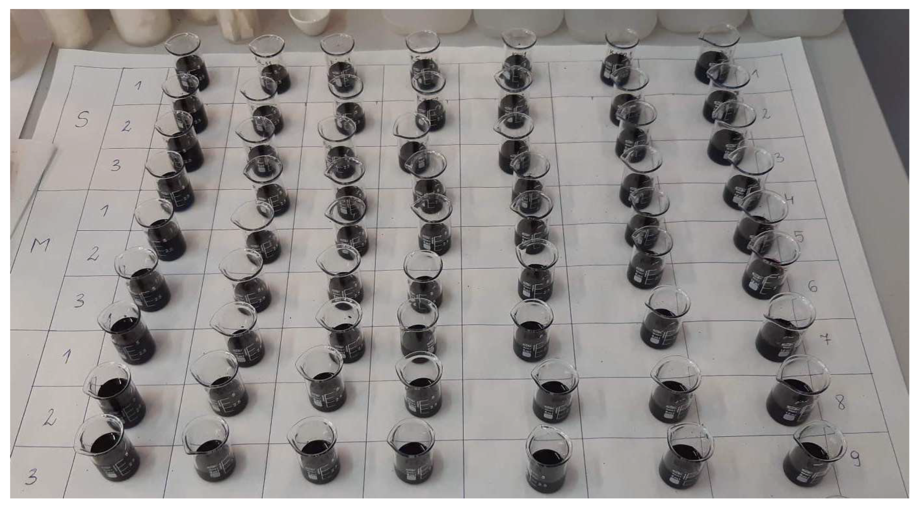
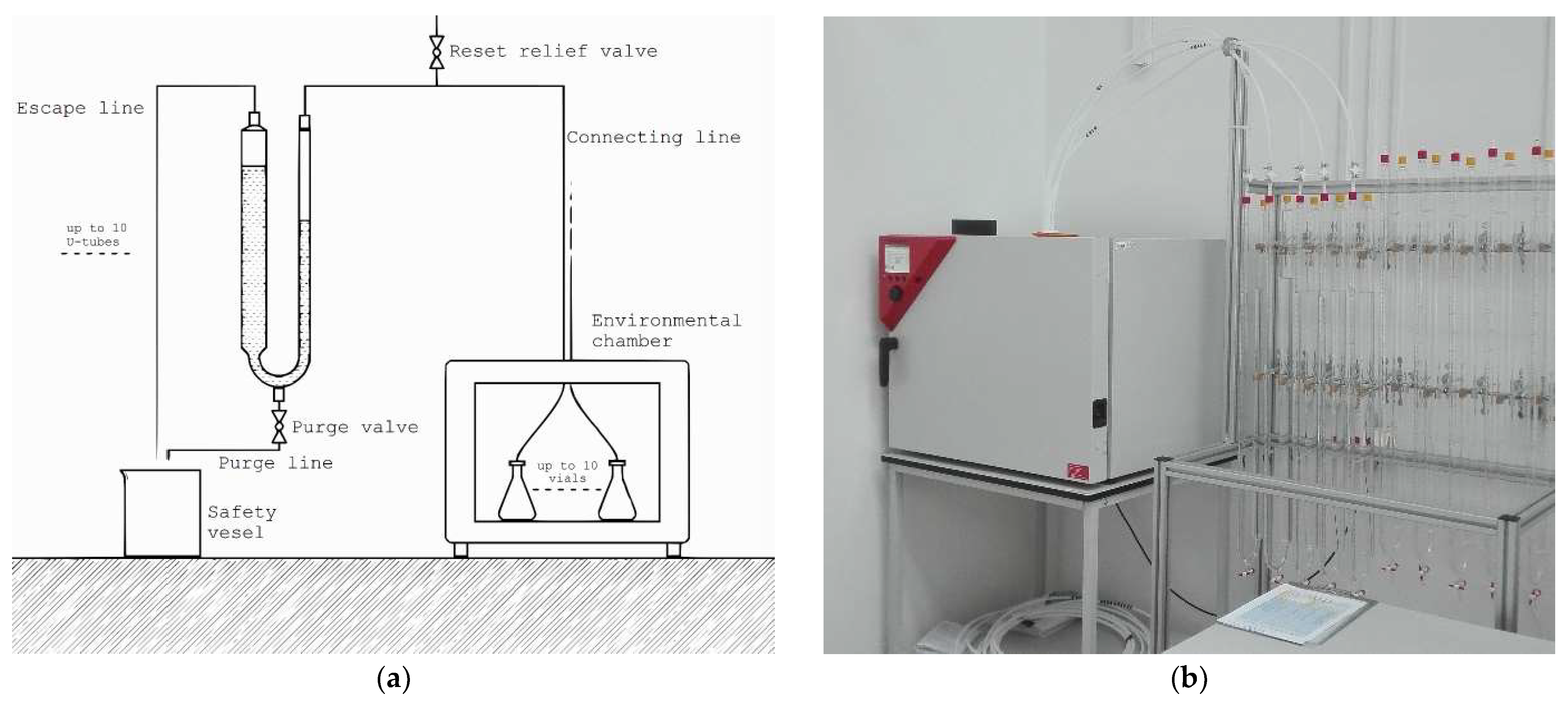
The method of choice for compatibility testing in POLON relies on positive gas displacement. To ensure that no friction occurs within the system, U-shaped tubes filled with water are used to measure the volume of evolved gases. This method has been successfully used in the past by Koopmans et al. [
42]. A similar approach has been taken before in NASA research [
43], accompanied with microcalorimetry. In this case, the testing setup, illustrated in
Figure 5, consists of 10 lines, each connecting a flask’s enclosure with a U-shaped tube with PTFE tubing. The flasks are contained within sealed isothermal incubator, capable of reaching temperatures in the range of 5 to 100 °C and maintaining the testing temperature with 0.5 °C accuracy.
Readouts taken with this method of measurement suffer from noise caused by variations in atmospheric pressure and temperature within the test room. A calculational algorithm has been developed to account for those variations and translate volumetric readouts into the μg/cm2d @ °C unit. For each test performed, one line is dedicated to a reference flask in which pure HTP is contained, wetting the same surface of the glass as in other samples. Usage of a reference flask allows capturing of non-monitorable variations in pressure as well as background decomposition rate of HTP in the glass flask, not connected to the sample itself. This approach, when properly executed, allows measurements of AOL as low as 5 μg/cm2d @ °C, which corresponds to AOL of 0.6% per year with surface-to-volume ratio of 1 dm−1. Such measurements, however, may be taken in weeks, instead of months, due to high accuracy of the system.
3.7. Diaphragm Propellant Tank Development
In order to tackle the long-term storability problem and provide an optimized solution for the POLON project, another key component which is developed in-house at Ł-IoA for POLON is the propellant tank. The main purpose of the propellant tank is to store the propellant (HTP) under pressure and provide required flow rate within the fluidic subsystem. Additionally, the propellant supplied from the propellant tank shall be gas free and within specified pressure range throughout whole satellite lifetime, at BOL as well as at EOL.
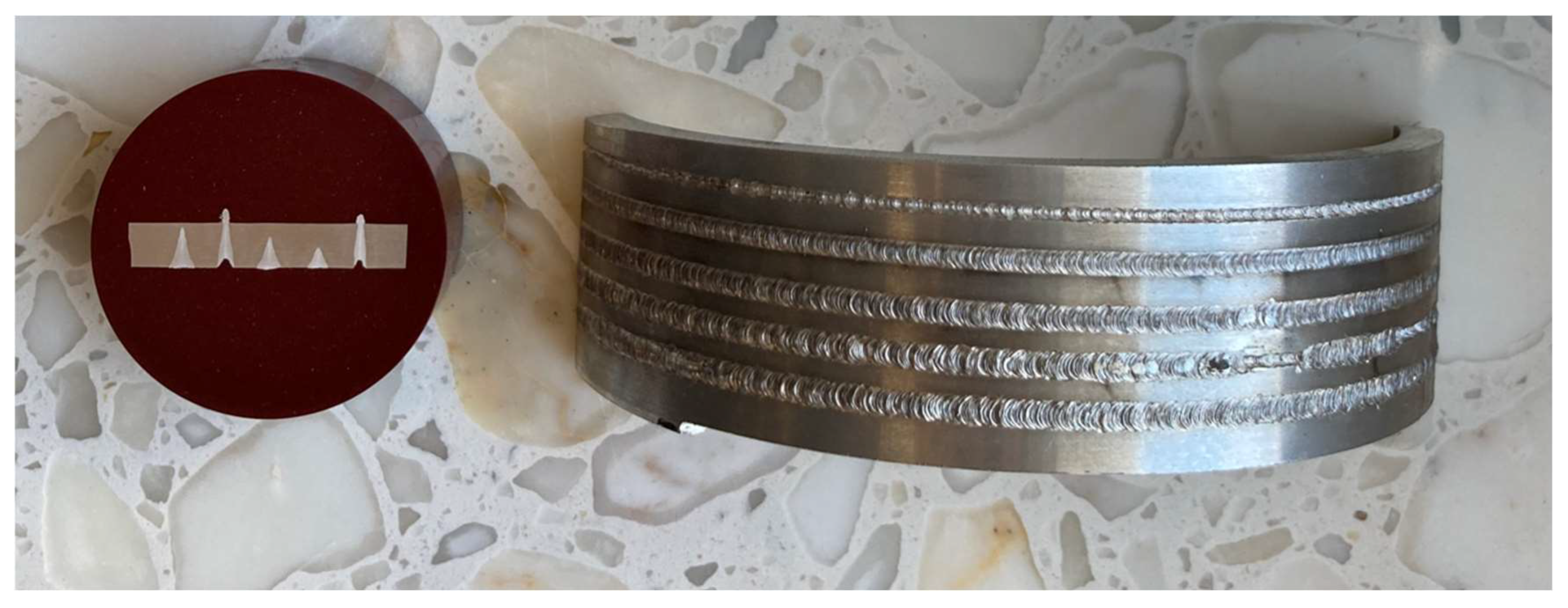
Based on selected propulsion system architecture, single propellant tank has been under development at Ł-IoA since the beginning of the project. During the initial phase of the project, the propellant tank shape was specified to be a cylindrical section with two ellipsoidal heads. The propellant tank shell is to be machined from aluminium alloy and then electron beam welded (EBW). Currently, further verification activities and initial tests of the EBW technology are ongoing. The trial EBW samples are shown in
Figure 6. Machining as well as EBW are well-established technologies regarding propellant manufacturing and have been widely used [
44,
45]. Moreover, the propellant tank will incorporate an elastomeric diaphragm as a positive expulsion device. A diaphragm was selected based on a thorough trade-off that highlighted many advantages of this method [
46,
47]. As a result of its construction, POLON propellant tank should be relatively lightweight, cost efficient, and provide additional advantage of fully demisable structure in case of deorbiting maneuver or uncontrolled re-entry.
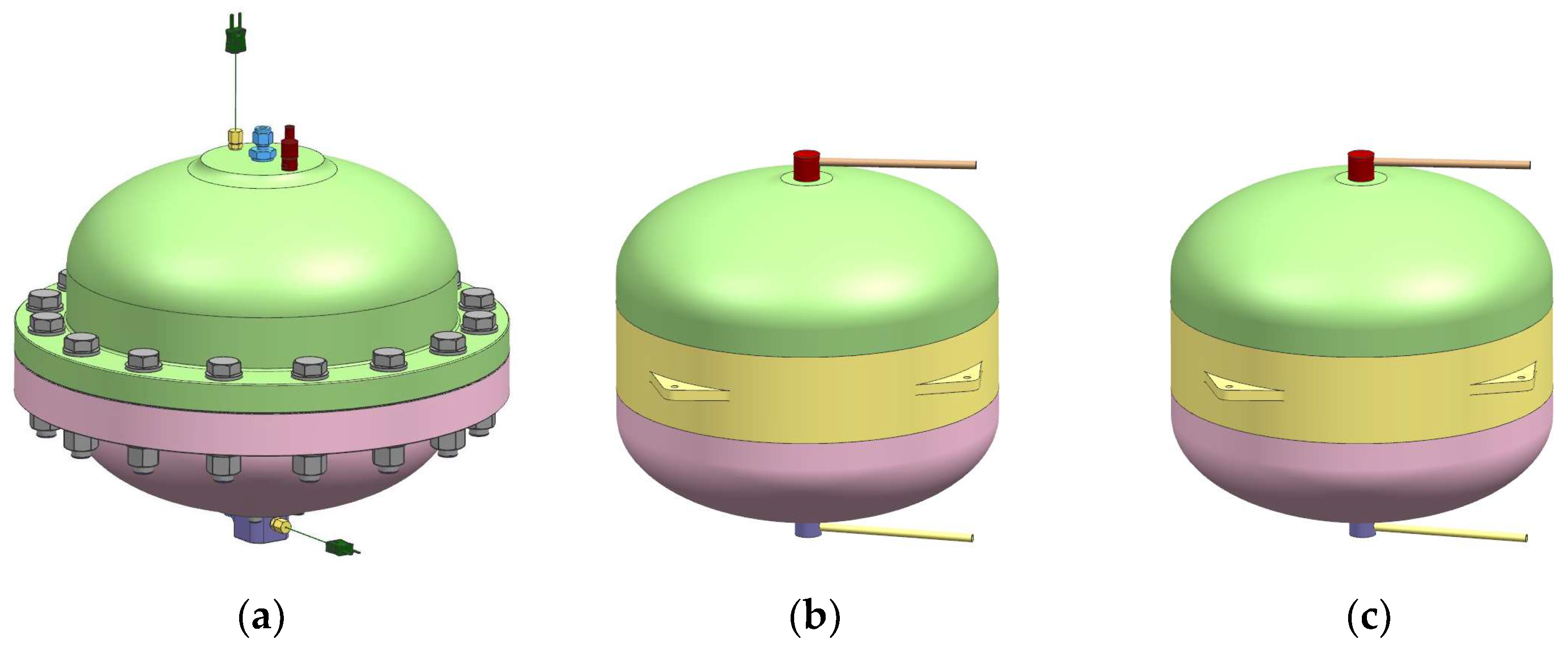
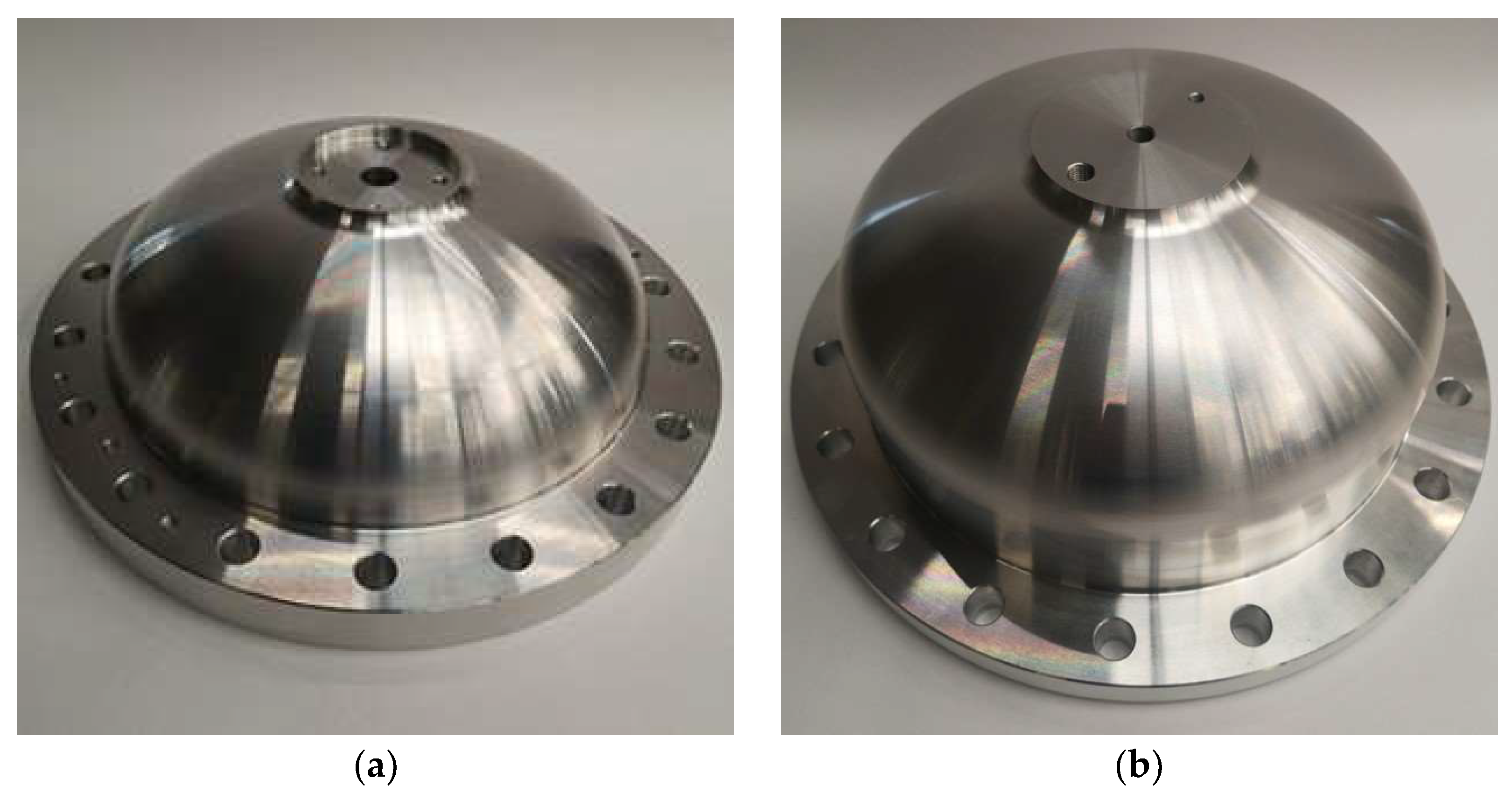
Propellant tank development plan for POLON propulsion module assumes design and manufacturing of three tanks in total, as presented in
Figure 7. Breadboard model was the first one to be built and will be used with the fluidic breadboard (
Figure 2).
Figure 8 shows parts of the breadboard tank that have already been manufactured. The main purpose of the breadboard model is to represent the propellant tank during fluidic breadboard test campaign, and therefore the design is provided with several measuring interfaces for both temperature and pressure measurements. During the breadboard testing, hydraulic waterhammer, diaphragm design, and tank performance will be subjected to thorough verification. Tank performance is to be verified based on expulsion efficiency, blowdown ratio, and internal leakage. Breadboard model was designed in order to represent the internal geometry while providing inspection capabilities and ensuring safety.
Following a successful fluidic breadboard test campaign, Ł-IoA intends to manufacture a qualification model of the propellant tank. The qualification model will be based on the results from the fluidic breadboard test campaign as well as relevant analysis (structural, thermal, and CFD). The aim of the qualification model is to properly qualify the design as well as the manufacturing processes at the component level. In order to achieve that, when manufactured, the qualification model will be subjected to thorough qualification testing. The test plan includes proof pressure testing, pressure cycling, thermal cycling, vibration testing, and eventually burst pressure testing.
Based on the results from the qualification process, propellant tank engineering model design will be verified. Ideally, the engineering model will be identical to the qualification model; however, Ł-IoA will allow minor improvements in the design. Eventually, the engineering model will be integrated with POLON propulsion module and used for propellant loading testing, and hot-fire testing.
3.8. Propellant Tank Loading Procedure Development
Propellant loading is an important element of spacecraft propulsion. The design shall enable accurate loading of a propellant, ensure adequate accuracy during pressurizing, and comply with applicable safety requirements at a particular launch site. The type of propulsion subsystem, fill and drain valve locations, used propellant, and method of pressurization all influence the method of loading [
48].
In order to enable efficient and rapid turnaround times of the POLON propulsion modules in the future, a dedicated GSE for propellant loading and testing cart is currently under development within the frame of the project in which one of the key ground operations is propellant loading.
The natural HTP decomposition forces avoiding the transport of a propulsion system already loaded with the propellant. Therefore, the propellant loading cart should be mobile and suitable to transportation to the launchpad. The loading cart should be compliant with the launch range safety requirements. Due to the simplification of propellant handling, the design of the stand is based on the principles suggested in the literature [
49]. That helps avoiding complex procedures used for toxic propellants, such as hydrazine.
To rapid loading time and risk reduction on launchpad, the procedure of loading will be determined and tested using the fluidic breadboard.
The POLON propulsion system design does not provide any venting during the propellant loading process. Therefore, the vacuum load method was selected for the propellant loading. The propellant loading tank procedure is presented in
Figure 9.
4. Technology Development Status and Results
4.1. Steady-State Performance Results
One of the most important results from the steady-state simulation is the blowdown curve, i.e., the relation between the system pressure and remaining fuel mass. Those data are needed to ensure that the thruster inlet pressure stays within the thruster qualification envelope. As shown in
Figure 10a, several curves were obtained by analysis. The simulations were initiated from the BOL conditions and included all thrusters operating until the emptying of the tank. For the tested temperatures (constant over whole simulation for simplification) from 5 °C up to 60 °C, the analysis proved that the blowdown ratio (BOL/EOL pressures ratio) stays near the nominal value of 4—
Figure 10b.
The second main characteristic resulting from the steady-state simulation is the general thruster performance, representing what thrust values can be expected at a given system state (e.g., pressure and temperature) and configuration. Several cases were investigated in order to properly reflect the whole mission profile. Therefore, the thrust ranges for the BOL and EOL could be assessed. Additionally, the pressure drop values on each system component were obtained. Generally, the steady-state results were used to assess the system preliminary performance in a time scale comparable with the designed mission duration, which confirmed the design and architecture viability. Further verification of the results will be performed with the fluidic breadboard test campaign and forthcoming simulations.
4.2. Minimum Impulse Bit Performance Results
The Minimum Impulse Bit (MIB), which is the lowest impulse bit achievable by the propulsion system, is a very informative parameter for an AOCS system design. MIBs can be used to control spacecraft orientation and orbit parameters with greater accuracy by establishing the lowest spacecraft velocity change (dV) associated with impulse—
Figure 11a. The MIB performance analysis supported creating 3D maps—
Figure 11b—of the thruster performance, which can be useful in further performance studies.
The impulse bits resulting from the analysis, which included the transient pressure changes, were compared with “ideal” impulses. The difference between the ideal impulse and the resulting impulse is mostly constant and stable for various input parameters; therefore, it can be deducted that transient pressure states (e.g., overshoot and thrust decay) do not change with impulse duration and inlet pressure.
However, for lower pressures and impulses shorter than 100 ms, the resulting impulse bit characteristic loses its near-linear relation to the impulse duration. This is illustrated in
Figure 11a. One explanation of the observed behavior is the fact that pressure oscillations in thrusters do not have enough time to settle during such a short impulse. Further studies of this phenomenon may yield interesting results for exploring extremely short impulses.
4.3. Waterhammer Results
The waterhammer simulations were needed for assessing the safety of the system, as the rapid opening/closing of the valves can lead to reducing the subsystem performance or even damaging some of the fluidic components. The simulation results determined the greatest pressure peak that can be expected in the system on the most exposed elements.
First, the influence of several parameters and different valve operations were established in order to assess the most dangerous events. It turned out that the two most dangerous cases were: priming the subsystem (opening the latch valve) and priming the thruster (opening the thruster valve). In both cases, while using the HTP as liquid, the pressure surge was 3–4 times higher than the static pressure (water used as a benchmark, resulted in a smaller pressure multiplier). Interestingly, the pressure surge in the interrupting thruster operation event was negligible.
The pressure surge appearing during the system priming could be reduced by a higher residual pressure in the evacuated lines—
Figure 12a—or by the introduction of an orifice in the main tubing, as illustrated in
Figure 12b. However, such an approach does not lead to reducing the maximum pressure peaks in the other two events.
4.4. Material Compatibility Results
Thus far, only a few of the required tests have been brought to fruition on a matured version of the compatibility testing apparatus. The potential diaphragm materials have been prioritized to secure cooperation with the manufacturers at a possibly early stage of the project. Aside from the potential diaphragm materials, stainless steel cylinders have been tested during the development phase of the apparatus. Material compatibility test results for the tank shell and tank diaphragm materials are listed in
Table 4.
4.5. Catalyst Bed Development Results
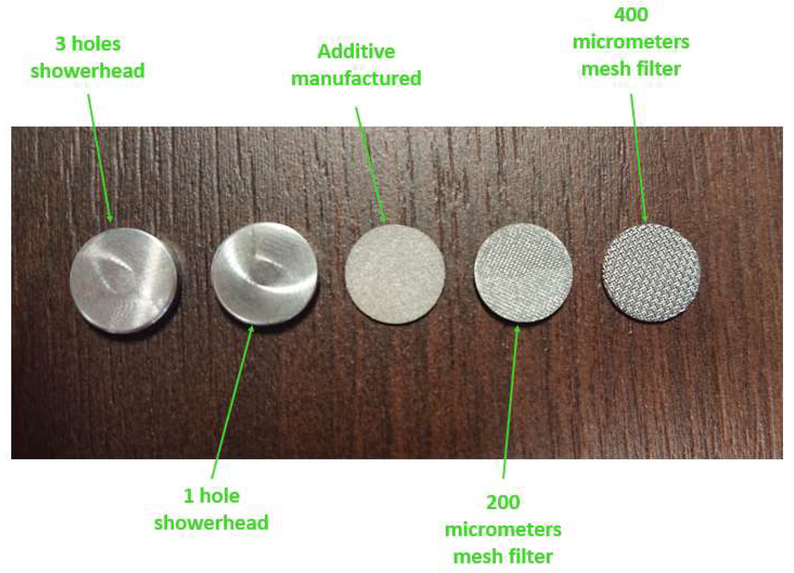
The injection method is essential to optimize the catalyst bed reaction time and lifetime. The 1N thrusters have limited injection possibilities because of a low mass flow. To optimize the injection, it is planned to test different configurations of injectors, such the configurations shown in
Figure 13.The injection can be different for a mission with a pulse mode, where the response time is important and different for steady-state firing.
Figure 14 shows a white cloud of mixed oxygen and water vapor created behind the nozzle. The cloud is visible in the first seconds of firing as a result of the incomplete propellant decomposition. It turns invisible with an increasing decomposition temperature.
The initial tests were prepared to compare the catalyst beds with different structures and materials of the active phase. The structures taken into consideration are pellets and foams. For the pellets, higher instabilities of pressure in the chamber were observed. The cause was the migration of the pellets while firing and the creation of voids. Foams tests are characterized by a higher repeatability of the results.
The catalyst beds based on manganese oxides were very active without preheating but were observed to experience a loss of the active phase. The catalyst beds with an active phase from platinum and silver had a higher repeatability and low response time. However, high raise times were observed for cold starts. The platinum and silver catalysts are much more promising and will be tested for a higher HTP throughput.
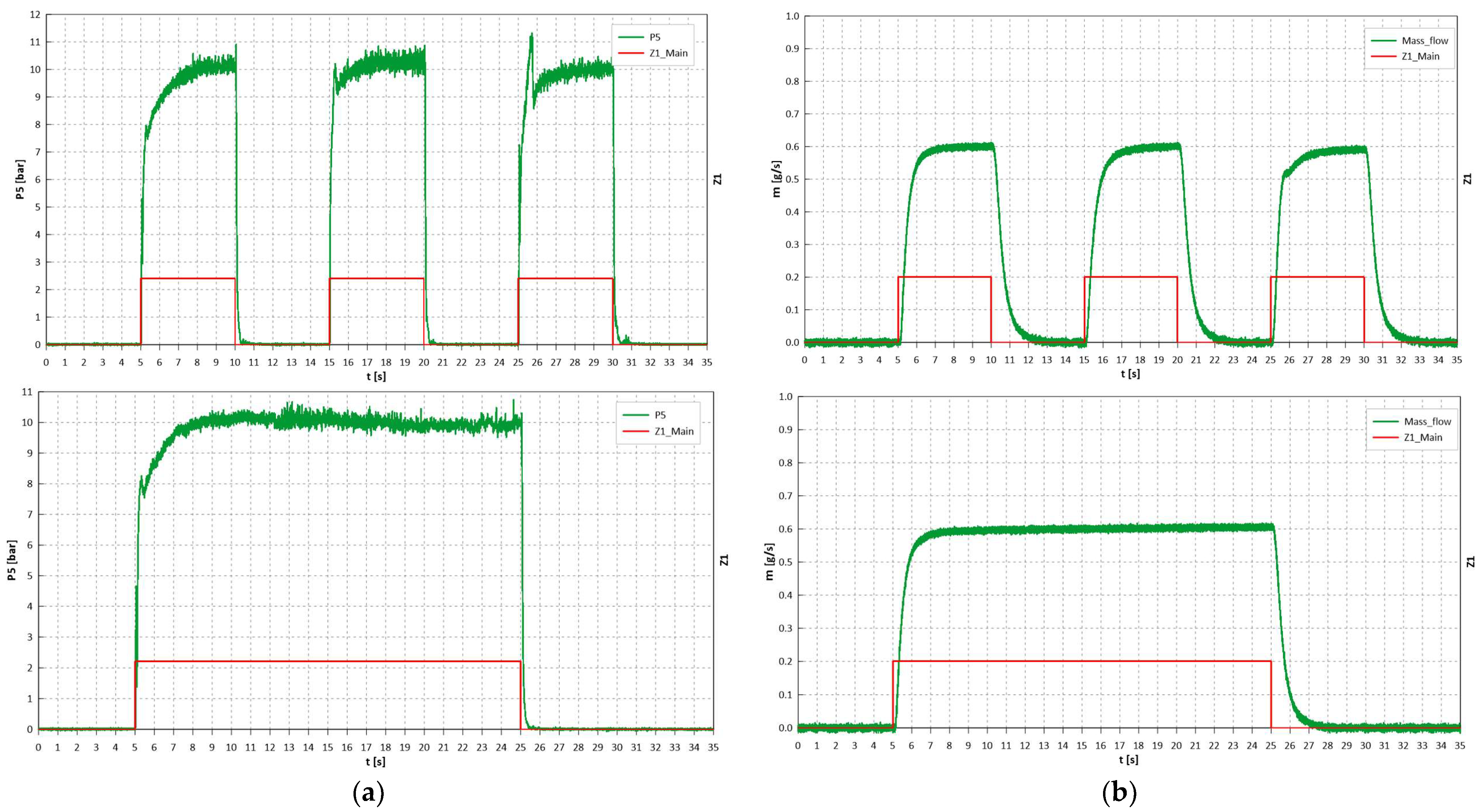
On the plots shown in
Figure 15, it can be observed that the mass flow stabilizes after 2 s, and the rise time of the pressure in the decomposition chamber is about 2.5 s. It is caused by a high dribble volume. The dribble volume is not critical when the lifetime of the catalyst beds is experimentally verified. It is important in the case of the pulse-mode operation. Therefore, pulse-mode testing with a minimum pulse time of 20 milliseconds will be conducted using the prototype model of the thruster. The initial prototype model test campaign included about 1000 tests.
5. Discussion
A selection of key design and development activities, associated with the development of POLON, a green microsatellite propulsion module using 98% Hydrogen Peroxide (HTP), was discussed. Although HTP is a propellant, whose advantages as a potential hydrazine replacement were recognized at the Ł-IoA over a decade ago, and significant expertise has already been gathered, incorporating this technology into a complete satellite propulsion system poses new challenges. As a result, a wide array of design, analysis, and test activities are conducted within the frame of the POLON project. Those are mainly related to system-level development efforts, such as the HTP propulsion system performance prediction and hydraulic system behavior verification, as well as component-level developments, such as the monopropellant thruster design and testing, diaphragm propellant tank development, and GSE development.
To date, the HTP propulsion performance prediction activities focused on the development of the MATLAB tools necessary for steady-state and transient phenomena prediction. As a result of steady-state modeling, the impact of pressure, temperature, and component parameters on the overall system performance could be estimated. This capability supported the propulsion system sizing, component selection process, and propellant line 3D layout optimization. Concurrently, transient simulations allowed for an investigation of the Minimum Impulse Bit (MIB) prediction and waterhammer pressure peak levels. Those analysis activities enabled making well-informed design decisions regarding the POLON fluidic subsystem design and configuration. As the project enters its next phase, the predictions will be verified experimentally using a fluidic breadboard test rig—a test setup enabling cold flow and hot-fire testing on the entire propulsion system, reflective of POLON. Apart from enabling the verification of the propulsion system performance, the fluidic breadboard will allow for performing auxiliary test activities, such as propellant loading trials. The fluidic breadboard is designed to be reconfigurable; so, in the future, it will also be used to conduct fundamental research on the waterhammer phenomena.
In terms of monopropellant development, the activity incorporates the catalyst bed assessment and selection as well as the thruster design, analysis, and test. The work on the catalyst bed, which is the critical element of the thruster, is heavily based around the expertise gathered during the previous Ł-IoA research campaigns. However, as the POLON thruster is aimed to deliver only 1N of thrust, new, otherwise cost- or mass-ineffective catalyst bed options are open. As a result, the test campaign included catalyst beds based on Manganese oxides, silver, and platinum. It was concluded that due to a higher repeatability and low response time, catalyst beds based on platinum and silver are the most promising candidates. Those candidates will be tested for higher HTP throughputs in the future. Concurrently to the catalyst bed selection, the testing of prototype injectors was performed. This activity is still ongoing, as the optimum injector configuration, satisfying both the steady-state performance and pulse-mode performance requirements, is being searched for.
The final category of the key design activities presented is based around propellant storage technologies. As the long-term in-orbit storage of HTP has widely been regarded as problematic, the development work undertaken within the frame of POLON heavily emphasizes HTP storage technologies. The work ranges from material compatibility research, through in-house propellant tank development, to the design of a propellant loading process and tooling. To date, both tank diaphragm and tank shell candidate materials were tested for compatibility with HTP at different temperature conditions. Although the research on the compatibility of different materials continues, the baseline propellant tank material has been selected, and the propellant tank breadboard model has already been manufactured.


 ,
, 


