
Thermal Design of Blackbody for On-Board Calibration of Spaceborne Infrared Imaging Sensor


Abstract
:1. Introduction
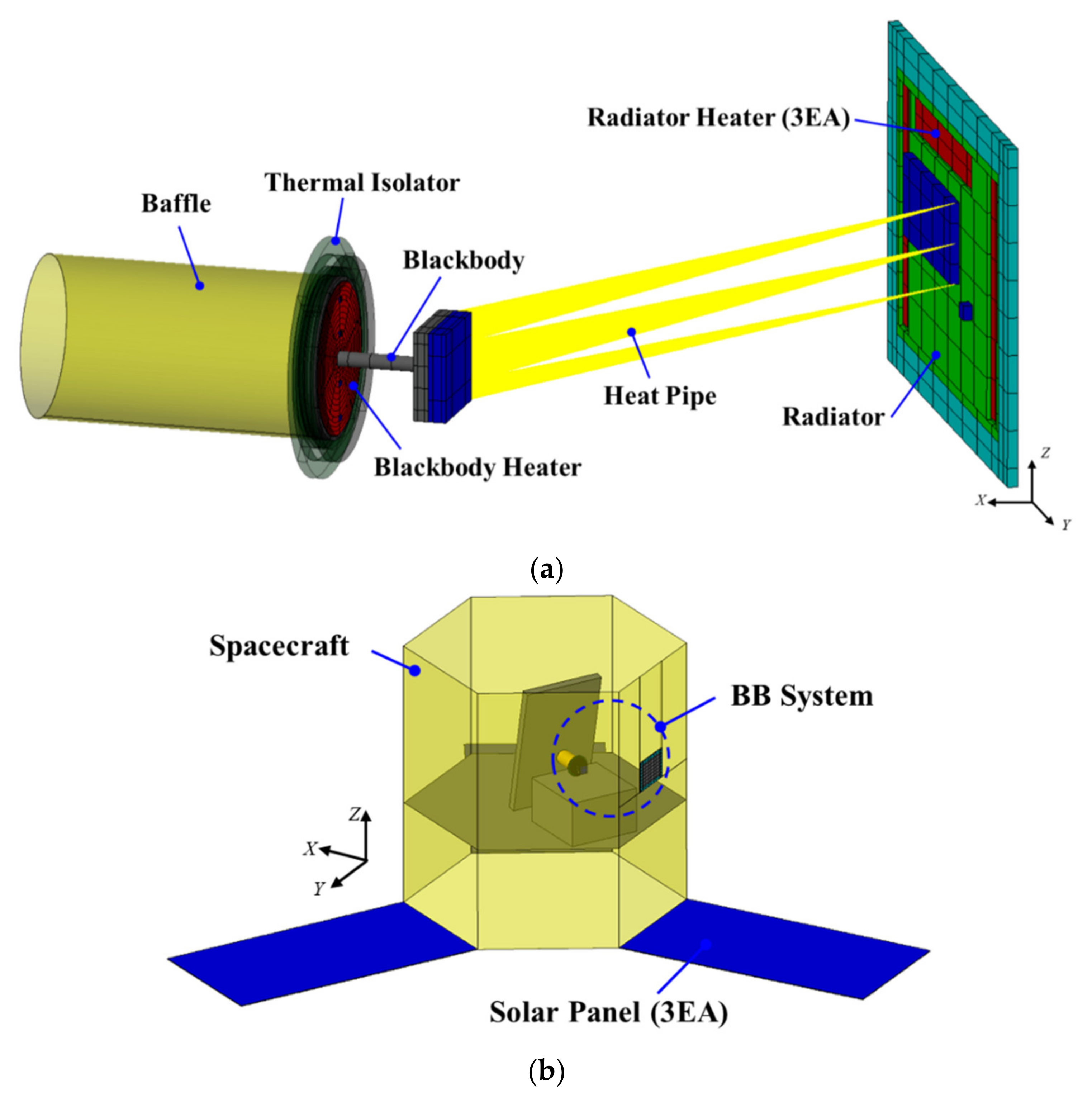
2. Thermal Design of On-Board BB
3. In-Orbit Thermal Analysis of On-Board BB
3.1. Thermal Mathematical Model
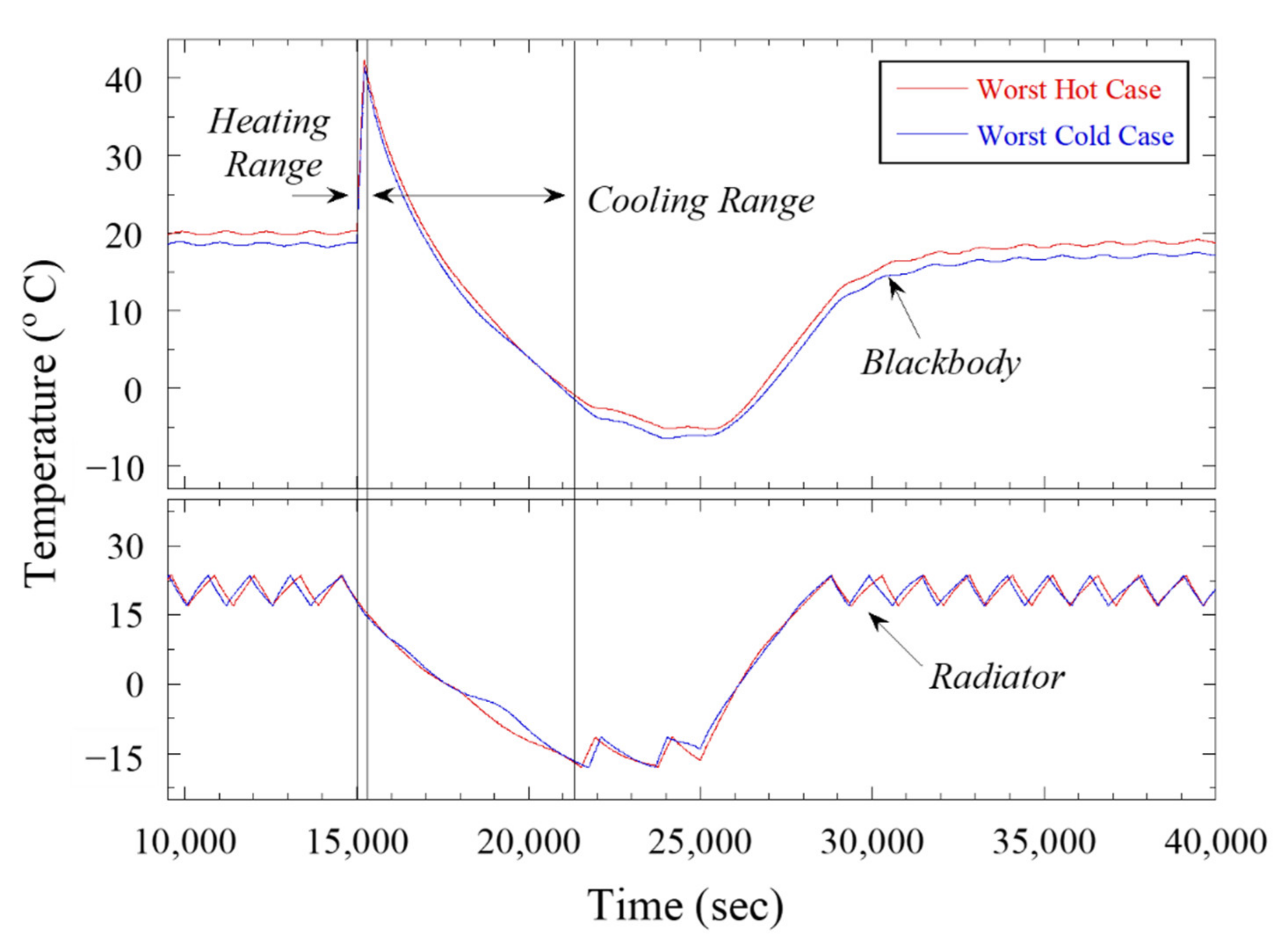
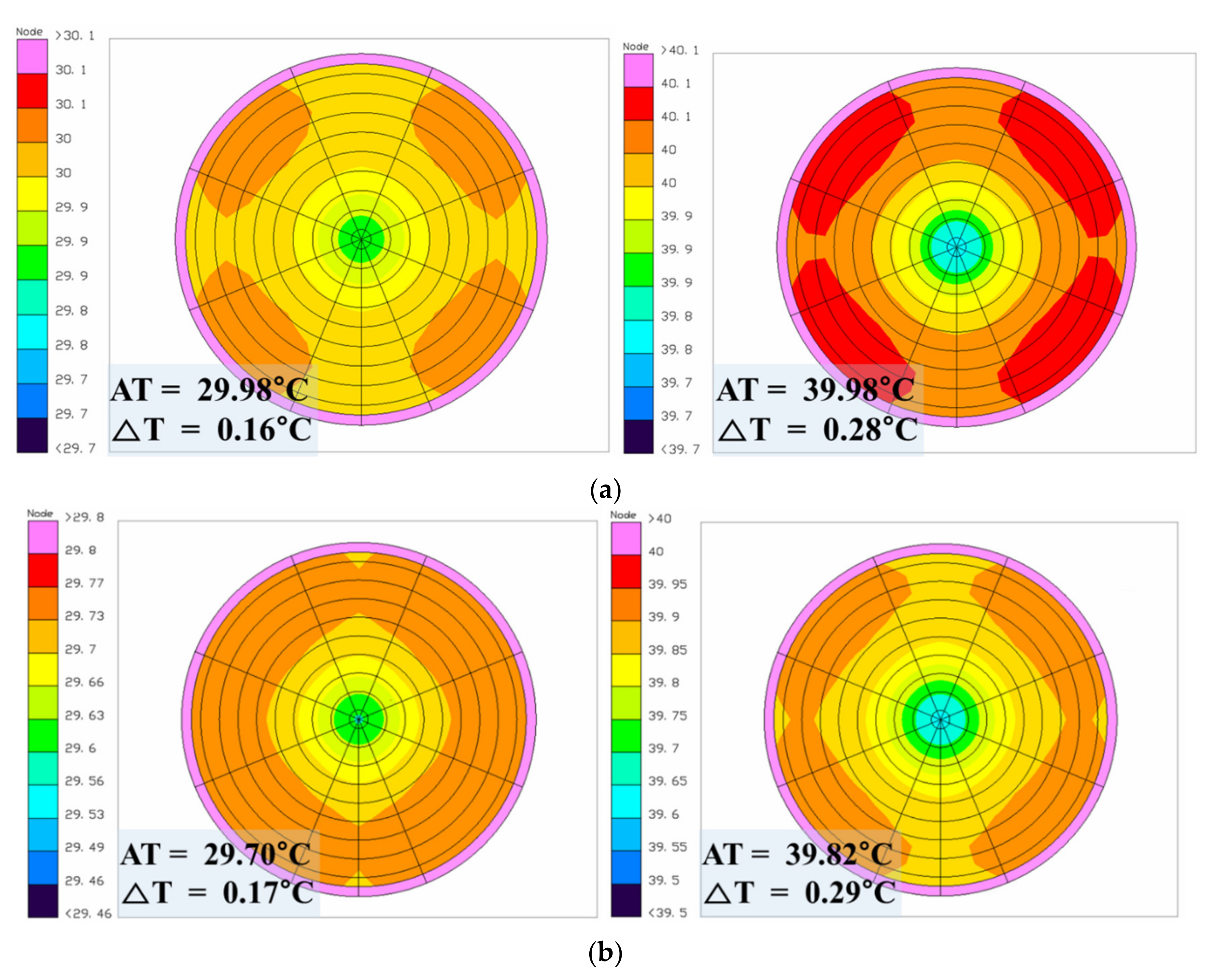
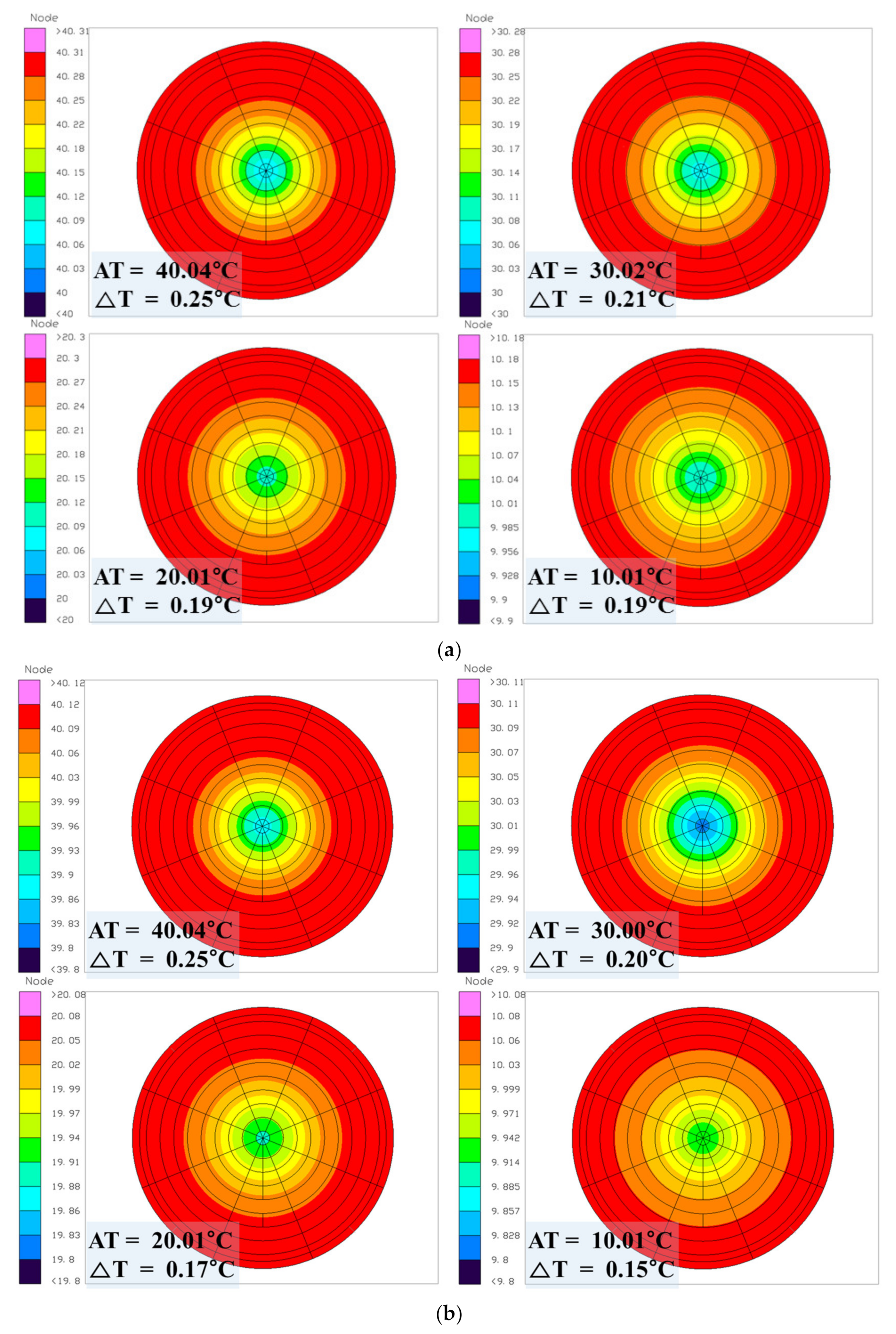
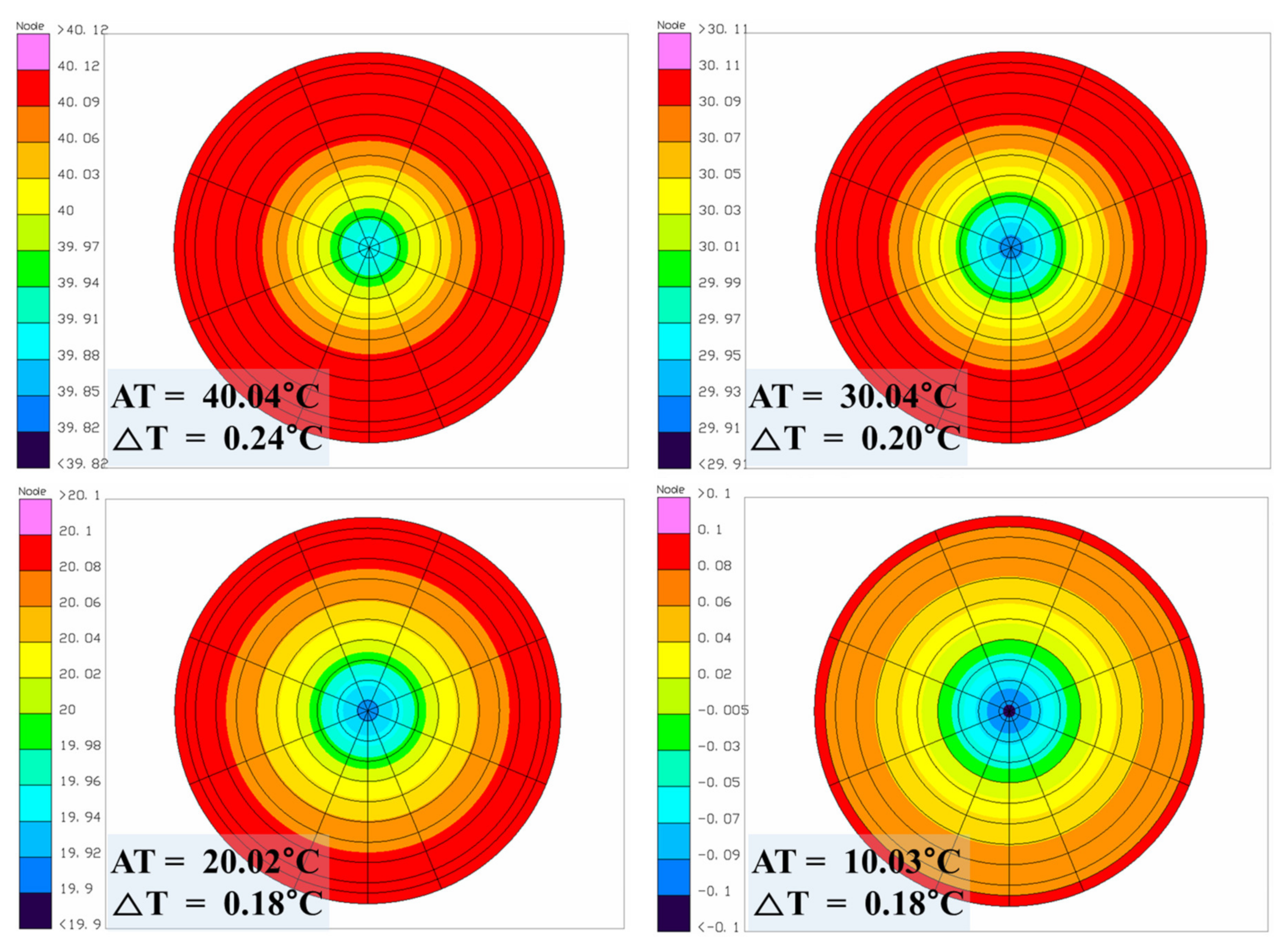
3.2. In-Orbit Thermal Analysis Results
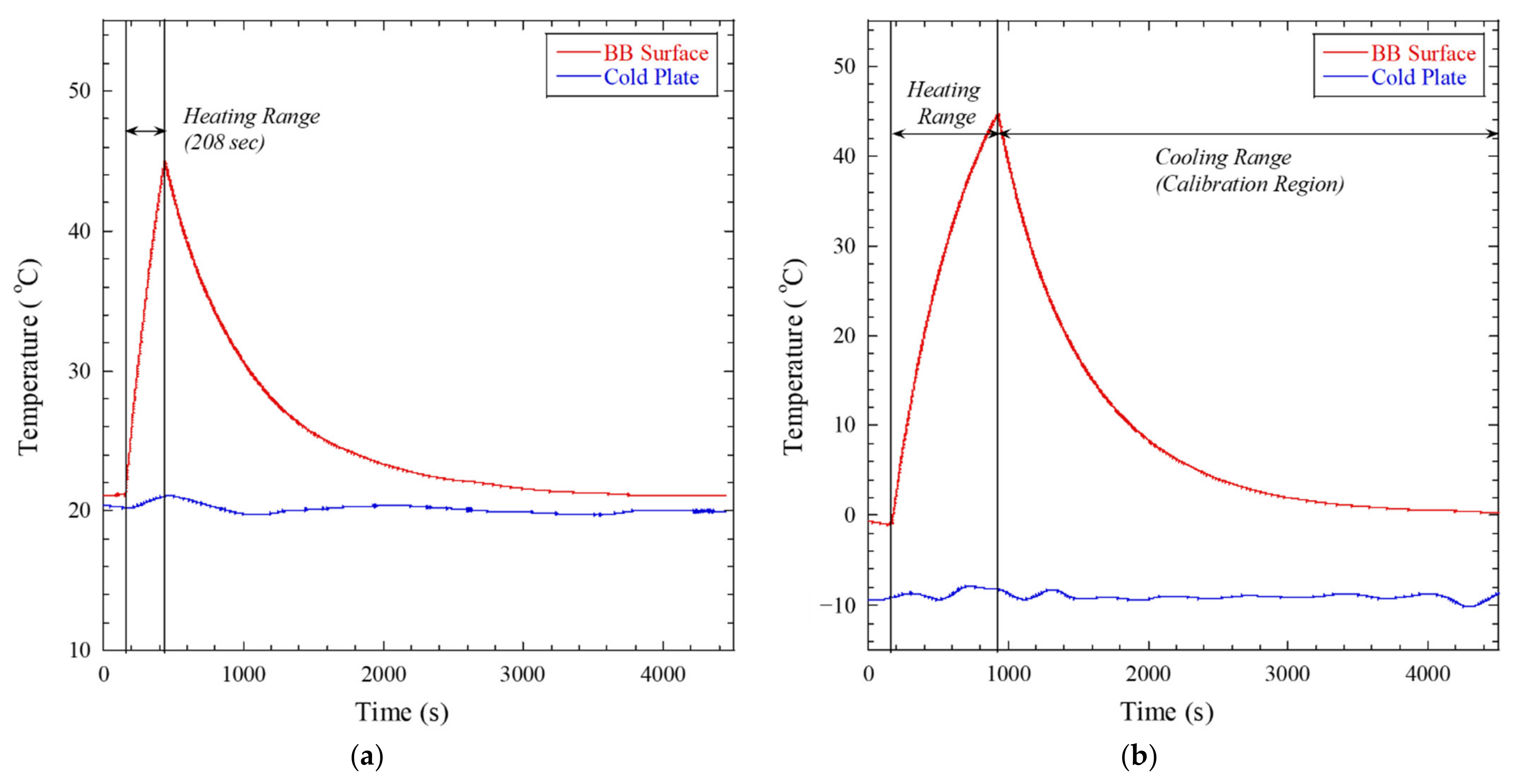
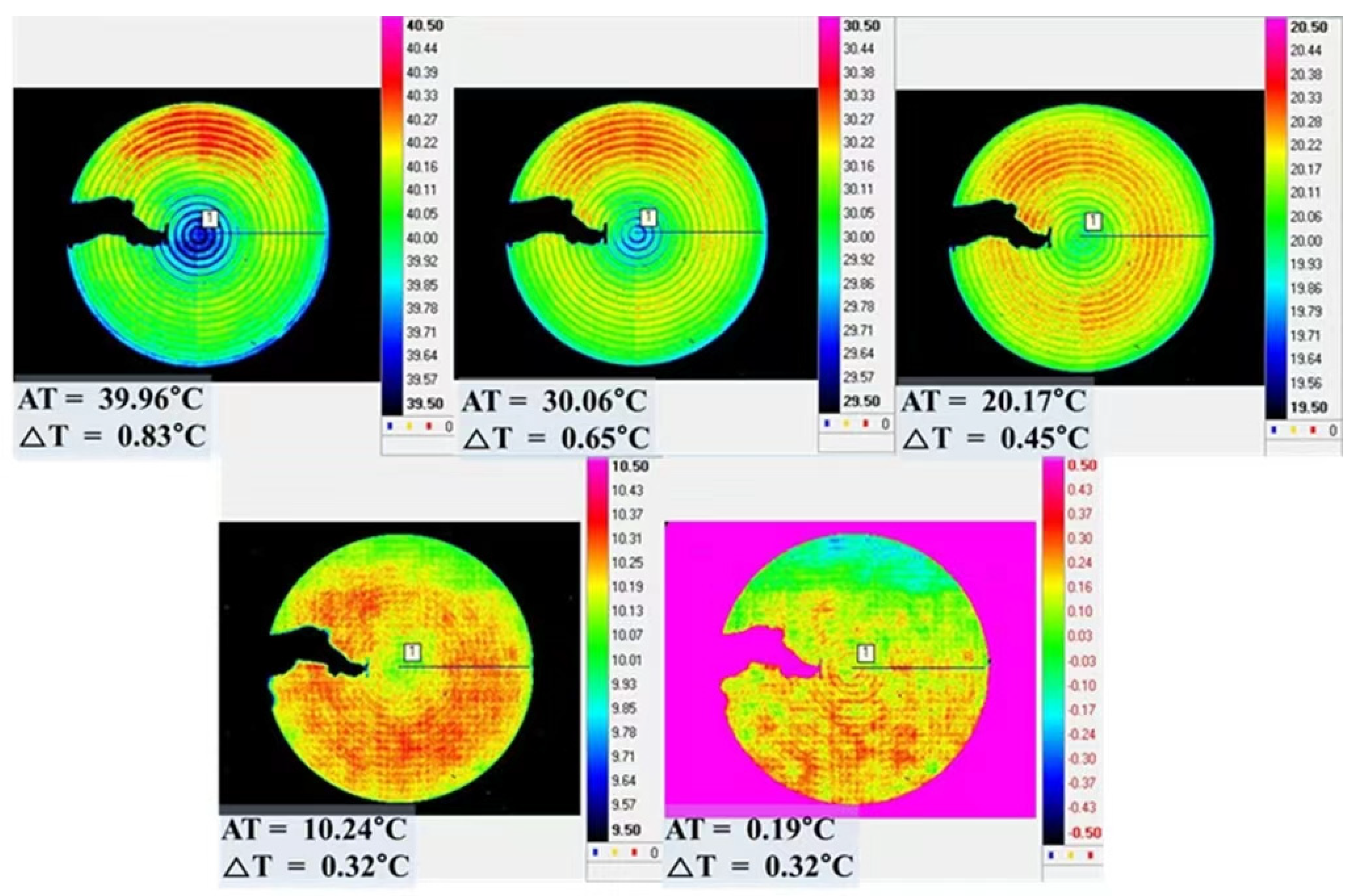
4. BB Heat-Up Test Results
5. Discussion and Conclusions
Author Contributions
Funding
Institutional Review Board Statement
Informed Consent Statement
Data Availability Statement
Conflicts of Interest
References
- Khare, S.; Singh, M.; Kaushik, B.K. Real time non-uniformity correction algorithm and implementation in reconfigurable architecture for infrared imaging systems. Def. Sci. J. 2019, 69, 179–184. [Google Scholar] [CrossRef]
- Çalık, R.C.; Tunali, E.; Ercan, B.; Oz, S. A Study on Calibration Methods for Infrared Focal Plane Array Cameras. VISIGRAPP 2018, 4, 219–226. [Google Scholar] [CrossRef]
- Sheng, M.; Xie, J.; Fu, Z. Calibration-based NUC Method in Real-time Based on IRFPA. Phys. Procedia 2011, 22, 372–380. [Google Scholar] [CrossRef] [Green Version]
- Lau, A.S. The Narcissus Effect in Infrared Optical Scanning Systems. In Stray Light Problems in Optical Systems; International Society for Optics and Photonics: Bellingham, WA, USA, 1977; Volume 107, pp. 57–63. [Google Scholar] [CrossRef]
- Mudau, A.; Willers, C.J.; Griffith, D.; le Roux, F.P.J. Non-uniformity correction and bad pixel replacement on LWIR and MWIR images. In Proceedings of the 2011 Saudi International Electronics, Communications and Photonics Conference, Riyadh, Saudi Arabia, 24–26 April 2011; pp. 1–5. [Google Scholar] [CrossRef]
- Sheng, Y.; Dun, X.; Jin, W.; Zhou, F.; Wang, X.; Mi, F.; Xiao, S. The On-Orbit Non-Uniformity Correction Method with Modulated Internal Calibration Sources for Infrared Remote Sensing Systems. Remote Sens. 2018, 10, 830. [Google Scholar] [CrossRef] [Green Version]
- Lee, S.Y.; Kim, G.H.; Lee, Y.S.; Kim, G.S. Thermal performance analysis of vacuum variable-temperature black-body system. Infrared Phys. Technol. 2014, 64, 97–102. [Google Scholar] [CrossRef]
- Miao, L.F.; Xu, Q.; Zhang, M.T.; Sun, D.X.; Liu, Y.N. Real-time implementation of multi-point non-uniformity correction for IRFPA based on FPGA. In International Symposium on Photoelectronic Detection and Imaging 2009: Advances in Infrared Imaging and Applications; International Society for Optics and Photonics: Bellingham, WA, USA, 2009; Volume 7383, pp. 1–8. [Google Scholar]
- Song, S.; Zhai, X. Research on non-uniformity correction based on blackbody calibration. In Proceedings of the 2020 IEEE 4th Information Technology, Networking, Electronic and Automation Control Conference (ITNEC), Chongqing, China, 12–14 June 2020; Volume 1, pp. 2146–2150. [Google Scholar] [CrossRef]
- Morozova, S.P.; Sapritsky, V.I.; Ivanov, V.S.; Lisiansky, B.E.; Melenevsky, U.A.; Xi, L.Y.; Pei, L. Facility for blackbody calibration. In Proceedings of the 7th International Symposium on Temperature and Thermal Measurements in Industry and Science, Delft, The Netherlands, 1–3 June 1999; pp. 587–592. [Google Scholar]
- Theocharous, E.; Fox, N.P.; I Sapritsky, V.; Mekhontsev, S.N.; Morozova, S.P. Absolute measurements of black-body emitted radiance. Metrologia 1998, 35, 549–554. [Google Scholar] [CrossRef]
- Sapritsky, V.I.; Khlevnoy, B.B.; Khromchenko, V.B.; Lisiansky, B.E.; Mekhontsev, S.N.; Melenevsky, U.A.; Morozova, S.P.; Prokhorov, A.V.; Samoilov, L.N.; Shapoval, V.I.; et al. Precision blackbody sources for radiometric standards. Appl. Opt. 1997, 36, 5403–5408. [Google Scholar] [CrossRef] [PubMed]
- Mason, I.M.; Sheather, P.H.; Bowles, J.A.; Davies, G. Blackbody calibration sources of high accuracy for a space-borne infrared instrument: The Along Track Scanning Radiometer. Appl. Opt. 1996, 35, 629–639. [Google Scholar] [CrossRef] [PubMed]
- Olschewski, F.; Ebersoldt, A.; Friedl-Vallon, F.; Gutschwager, B.; Hollandt, J.; Kleinert, A.; Monte, C.; Piesch, C.; Preusse, P.; Rolf, C.; et al. The in-flight blackbody calibration system for the GLORIA interferometer on board an airborne research platform. Atmos. Meas. Tech. 2013, 6, 3067–3082. [Google Scholar] [CrossRef] [Green Version]
- Monte, C.; Gutschwager, B.; Adibekyan, A.; Kehrt, M.; Ebersoldt, A.; Olschewski, F.; Hollandt, J. Radiometric calibration of the in-flight blackbody calibration system of the GLORIA interferometer. Atmos. Meas. Tech. 2014, 7, 13–27. [Google Scholar] [CrossRef] [Green Version]
- Xiong, X.; Chiang, K.; Esposito, J.; Guenther, B.; Barnes, W. MODIS on-orbit calibration and characterization. Metrologia 2003, 40, S89–S92. [Google Scholar] [CrossRef]
- Xiong, X.; Barnes, W. An overview of MODIS radiometric calibration and characterization. Adv. Atmos. Sci. 2006, 23, 69–79. [Google Scholar] [CrossRef]
- Oh, H.-U.; Shin, S. Numerical study on the thermal design of on-board blackbody. Aerosp. Sci. Technol. 2012, 18, 25–34. [Google Scholar] [CrossRef]
- Oh, H.-U.; Shin, S.; Kim, J.-M. On-Orbit Performance Prediction of Black Body Based on Functional Test Results under Ambient Condition. J. Aerosp. Eng. 2012, 25, 39–44. [Google Scholar] [CrossRef]
- Oh, H.-U.; Lee, M.-J.; Kim, T. Experimental Design Validation of Tilting Calibration Mechanism by Using Shape Memory Alloy Spring Actuator. Int. J. Aerosp. Eng. 2017, 2017, 1–12. [Google Scholar] [CrossRef] [Green Version]
- Thermal Desktop User’s Guide, Ver. 6.1; Network Analysis Associates: Tempe, AZ, USA, 2006.
- SINDA/FLUINT User’s Guide, Ver. 6.1; Network Analysis Associates: Tempe, AZ, USA, 2006.


| Specifications | 9 mm Heat Pipe |
|---|---|
| Material | Al6063 |
| Working Fluid | NH3 |
| Outer Diameter | 9 mm |
| Inner Diameter | 6.7 mm |
| Evaporator Length | 50 mm |
| Condenser Length | 80 mm |
| Item | Total Heat Dissipation (W) | On/Off Set-Point (°C) | Remark |
|---|---|---|---|
| BB Heater | 40.83 | − | − |
| Radiator Heater | 30 (3EA) | 17/23 | Non-calibration Region |
| −18/−12 | Calibration Region |
| Material Properties | ||||
| Material | Conductivity (W/m/K) | Density (kg/m3) | Specific Heat (J/kg/K) | Remark |
| Al-6063 | 200 | 2768 | 879.2 | BB, radiator |
| Al-6061 | 170 | 2768 | 879.2 | Baffle |
| Heater | 0.12 | 1410 | 1090 | Heater |
| G10 | 0.288 | 1850 | 1400 | Thermal isolator |
| Ti-6Al-4V | 17 | 4430 | 1590 | Flange |
| Thermo-Optical Properties | ||||
| Material | Solar Absorptivity (α) | IR Emissivity (ε) | α/ε | Remark |
| Acktar black coating | 0.98 | 0.98 | 1 | BB (front side) |
| MLI | 0.05 | 0.05 | 1 | BB (rear side), heat pipe, radiator (internal) |
| OSR | 0.24 | 0.80 | 0.3 | Radiator (external) |
| White paint | 0.70 | 0.90 | 0.78 | Solar panel (rear side) |
| Component | Value | Remark | |
|---|---|---|---|
| From | To | ||
| BB Flange | Radiator flange | 2.294 W/K | Heat pipe normal operation |
| 1.2 W/K | One heat pipe failure | ||
| Blackbody | Thermal isolator | 48 W/m2/K | Thermal washer |
| Thermal isolator | Baffle | 48 W/m2/K | Thermal washer |
| Blackbody heater | Blackbody | 2000 W/m2/K | Coupling |
| Radiator heater | Radiator | 2000 W/m2/K | Coupling |
| Parameter | Orbit Condition | |
|---|---|---|
| Worst Hot | Worst Cold | |
| Orbit Type | Sun Synchronous Orbit | |
| Period (min) | 95.88 | |
| Solar flux (W/m2) | 1420 | 1284 |
| Albedo coefficient | 0.35 | 0.3 |
| IR flux (W/m2) | 249 | 227 |
| Boundary condition (°C) | 25 | 15 |
| Worst Hot | Heat Pipe Normal Operation | One Heat Pipe Failure | Remark | ||
|---|---|---|---|---|---|
| Worst Hot | Worst Cold | Worst Hot | Worst Cold | ||
| Heating time (s) | 224 | 230 | 224 | 230 | <500 |
| Maximum temperature on BB surface (°C) | 42.46 | 41.38 | 42.18 | 41.15 | >40 |
| Cooling time (s) | 5793 | 5721 | 6138 | 6033 | <10,800 |
| Maximum ΔT in cooling range (°C) | 0.25 | 0.25 | 0.24 | 0.23 | <1 |
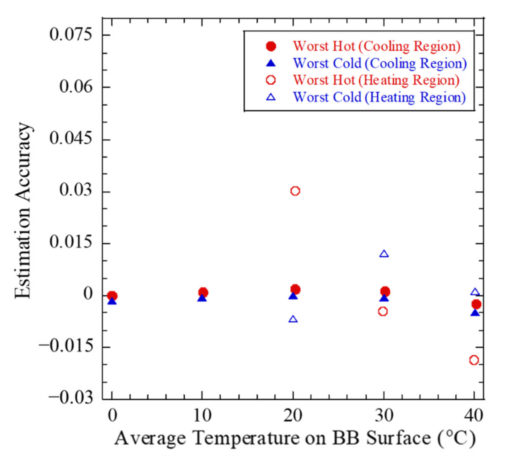
| Estimation accuracy (°C) | 0.0025 | 0.0049 | - | - | - |
| Radiator heater duty cycle (%) | 44.78 | 44.74 | 40.86 | 40.83 | <80 |
Publisher’s Note: MDPI stays neutral with regard to jurisdictional claims in published maps and institutional affiliations. |
© 2022 by the authors. Licensee MDPI, Basel, Switzerland. This article is an open access article distributed under the terms and conditions of the Creative Commons Attribution (CC BY) license (https://creativecommons.org/licenses/by/4.0/).
Share and Cite
Kim, H.-I.; Chae, B.-G.; Choi, P.-G.; Jo, M.-S.; Lee, K.-M.; Oh, H.-U. Thermal Design of Blackbody for On-Board Calibration of Spaceborne Infrared Imaging Sensor. Aerospace 2022, 9, 268. https://doi.org/10.3390/aerospace9050268
Kim H-I, Chae B-G, Choi P-G, Jo M-S, Lee K-M, Oh H-U. Thermal Design of Blackbody for On-Board Calibration of Spaceborne Infrared Imaging Sensor. Aerospace. 2022; 9(5):268. https://doi.org/10.3390/aerospace9050268
Chicago/Turabian StyleKim, Hye-In, Bong-Geon Chae, Pil-Gyeong Choi, Mun-Shin Jo, Kyoung-Muk Lee, and Hyun-Ung Oh. 2022. "Thermal Design of Blackbody for On-Board Calibration of Spaceborne Infrared Imaging Sensor" Aerospace 9, no. 5: 268. https://doi.org/10.3390/aerospace9050268