Article

Combustion Characteristics of a Supersonic Combustor with a Large Cavity Length-to-Depth Ratio

1
School of Power and Energy, Northwestern Polytechnical University, Xi’an 710072, China
2
China Aerodynamic Research and Development Center, Mianyang 621000, China
*
Author to whom correspondence should be addressed.
Aerospace 2022, 9(4), 214; https://doi.org/10.3390/aerospace9040214
Submission received: 17 March 2022 / Revised: 11 April 2022 / Accepted: 12 April 2022 / Published: 14 April 2022
(This article belongs to the Special Issue Advanced Flow Diagnostic Tools)

Abstract

:
The combustion characteristics of a hydrogen-fueled supersonic combustor featuring a large cavity length-to-depth ratio (i.e., 11) were examined by performing experimental trials while varying the fuel injector positions and equivalence ratios. During these trials, flame chemiluminescence images were acquired simultaneously from the side and bottom of the combustor under Mach 2.0 inflow conditions. The flame was observed to stabilize inside the cavity under all conditions. Proper orthogonal decomposition (POD) and dynamic mode decomposition (DMD) analyses of sequential flame chemiluminescence images demonstrated the important effects of oblique shocks induced by fuel injection and heat release on flame stabilization. Because fluctuations in the locations of the flame and of the intense heat release zone were not observed and no dominant frequency was identified in POD and DMD analyses, the present configuration was evidently able to suppress combustion instability. The present research provides preliminary guidance for exploring the feasibility of using cavity combustors with large length-to-depth ratios in scramjet engines.

1. Introduction

Scramjet engines are promising candidates for efficient air-breathing propulsion at high flight Mach numbers; however, it is challenging to achieve flame stabilization and efficient combustion in such engines because the residence time of the flow in the combustor is on the order of milliseconds [1,2,3,4]. To resolve this problem, a cavity flame holder has been proposed as a means of achieving robust flame holding and stabilization. Huellantel et al. [5] first demonstrated the feasibility of utilizing a flameholding cavity structure in conjunction with supersonic flow in the 1950s. Following this initial work, various aspects of cavity-based supersonic combustors were investigated, such as flame stabilization modes [2,6,7,8,9,10,11,12,13,14,15,16] and oscillation characteristics [11,12,17,18,19,20,21,22,23,24,25]. The simplified structure, improved flameholding characteristics and lower total pressure losses of cavity-based supersonic combustors have resulted in the application of these units to supersonic combustion scramjet engines.
There has been a substantial amount of research concerning the mixing and stabilization characteristics associated with supersonic flow in recent years, and the transverse injection of fuel from a wall orifice has been shown to be a simple yet effective means of enhancing mixing. Ben-Yakar et al. [26] experimentally investigated the mixing characteristics of hydrogen and ethylene transverse jets. Their results demonstrated that an ethylene transverse jet penetrated deeper into the freestream than a hydrogen jet at the same jet-to-freestream momentum flux ratios. This difference was attributed to variations in the large-scale coherent structures present in the jet shear layers. Because they provide reduced drag force, cavity flameholders featuring small length-to-depth ratios have received special attention. As an example, Choi et al. [27] numerically assessed the flow characteristics of a supersonic combustor with transverse hydrogen injection and reported that the intrinsic unsteadiness induced by shear layer instability, shock waves and fuel injection generated oscillatory flow, although a dominant frequency was not observed in the case of a reacting flow. Liu et al. [9] investigated the unsteady characteristics of an ethylene jet flame ignited by a pulse laser by simulating reactive flows in a scramjet combustor using a high-accuracy LES. The heat released during the associated chemical reaction was found to play an important role in the variation of the temperature field within the cavity. The configuration of the cavity is also a key parameter affecting both mixing and stabilization during supersonic flow. Huang et al. [13,14,15] analyzed the effects of the equivalence ratio and the injector position on transitions between flame modes and also assessed the effects of backpressure on the mixing process. Ouyang et al. [24,25] experimentally examined the effects of cavity parameters and the equivalence ratio on combustion oscillations in scramjet combustors and determined that the distance between the ethylene injector and the cavity played an important role in the onset of combustion instability. With advances in combustion diagnostics and the use of statistical methods, more detailed information has become available. Micka and Driscoll [21] discovered two distinct combustion stabilization modes for a system based on hydrogen injection upstream of a cavity and investigated the transition between these two modes using pressure measurements. On the basis of high-speed CH* chemiluminescence, shadowgraph analyses and pressure measurements, six typical combustion modes were reported to occur in a scramjet model combustor within the relatively low frequency of 100–500 Hz using the proper orthogonal decomposition (POD) and dynamic mode decomposition (DMD) methods [11]. Further investigation demonstrated that vortexes formed by boundary layer separation and temporal thermal choke produced oscillations between the jet wake flame and the cavity shear-layer stabilized ram combustion [12].
The research described above was primarily conducted using cavities with length-to-depth ratios of less than 7, and there have been very few studies regarding the flame stabilization of cavities with large ratios. Li et al. [28] experimentally investigated the effects of cavity geometry on the combustion processes in a Mach 2 supersonic flow and found that a large length-to-depth ratio promoted combustion. Tian et al. [29] applied five non-intrusive measurement techniques simultaneously to obtain more comprehensive information regarding the combustion characteristics in a cavity combustor with a length-to-depth ratio of 11. Xiong et al. [30] also studied the ignition and combustion characteristics in the same cavity-based supersonic combustor at low stagnation temperature and pressure.
The above discussion indicates that, although the flow structures and combustion characteristics of cavity-based scramjet engines have been investigated for several decades, certain phenomena, as well as the flameholding and oscillation combustion mechanism, have not yet been fully elucidated. This is especially true with regard to flameholding and oscillation combustion characteristics at large length-to-depth ratios. On this basis, the present study performed a series of comparative experiments using different injector positions and various equivalence ratios in a cavity-based supersonic combustor with a length-to-depth ratio of 11, and POD and DMD analyses were applied to chemiluminescence images captured using a high-speed camera at 20 kHz. The results of the present research were compared with previous studies to investigate the effects of the length-to-depth ratios on the flameholding and oscillation combustion characteristics. Additionally, the effects of oblique shocks induced by the fuel jet on flameholding and combustion instability were also examined.

2. Experimental Setup

Experimental investigations were carried out on a direct-connected supersonic combustion facility within the China Aerodynamics Research and Development Center. During these trials, a high enthalpy airflow with a stagnation temperature of 950 K and stagnation pressure of 0.82 MPa was obtained by employing a hydrogen-fueled heater. Make-up oxygen was added to maintain a 21% O2 mole fraction, the molar composition of the airflow at the isolator entrance was 21% O2, 12% H2O and 67% N2, and the Mach number was 2.0.
Figure 1 provides a diagram of the combustor and the associated data acquisition system. In this apparatus, a cavity with a depth of 11 mm and a length of 121 mm was connected to the downstream of the isolator. There were two fuel injection positions, as shown in Figure 1. The first injector (K1) was located at the isolator 15 mm from the cavity step; the second injector (K2) was situated on the top wall of the cavity at an axial position 25 mm from the cavity step. Hydrogen was injected vertically into the airflow by ten holes (each with a diameter of 1 mm) at specific positions according to the experimental requirements. Three quartz windows were installed to allow chemiluminescence images to be captured: two on the side walls and one on the bottom of the cavity. More detailed descriptions of the experimental system can be found in prior publications [30,31]. As shown in Figure 1b, the data acquisition system comprised a high-speed camera (IX i-speed 720, Essex, UK) and two fiber-based endoscopes (FBEs) combined with two 50 mm f/2.8 Nikon prime lenses (Tokyo, Japan), allowing simultaneous observations of the combustion process in the cavity from two perspectives. The FBE1 faced the side wall quartz window; the FBE2 faced the window on the base of the apparatus. Chemiluminescence images of the combustion products were captured at a framerate of 20 kHz. The field of view of FBE1 was limited to the region indicated by dark shading in Figure 1a to ensure the frame rate. The parameters applied during the experimental trials are summarized in Table 1.

3. Results

3.1. Chemiluminescence Images

In accordance with the research of Schefer et al. [32,33], the chemiluminescence signal of hydrogen–air flame mainly comes from H2O*, which is generated in an exothermic process; therefore, the chemiluminescence signal here is used to reflect heat release. Figure 2 shows the instantaneous, averaged and standard deviation of side-view flame chemiluminescence images acquired under different conditions. From both the instantaneous and averaged images, it is evident that the flame zone was located within the cavity in each trial. In the case of Φ = 0.2, the intensity of the averaged image acquired with hydrogen injected from the upstream injector was greater than that acquired with the injector inside the cavity. This result indicates that the hydrogen underwent more vigorous combustion when injected from the upstream position at a given equivalence ratio. This same phenomenon was also reported by Tian et al. [29] and was attributed to improved fuel–air mixing [30]. The standard deviation images show the variation in the chemiluminescence as a function of spatial positions, which are indicative of regions of heat release fluctuations. As seen, a uniform degree of variation in chemiluminescence signals (and presumably heat release) occurred within the cavity.
Figure 3a presents the averaged flame brush extracted from the chemiluminescence images, from which it is apparent that the flame expanded into the mainstream with increases in Φ when using the K1 injector. In addition, the flame brush obtained in conjunction with the K2 injector exhibited greater distortion compared with the K1 cases. Figure 3b shows the outermost edges of the standard deviation images and demonstrates that the outermost edges with higher Φ values tended to expand into the mainstream. Because the standard deviation varied according to the region where the flame was located, the edges of these standard deviation images became more representative of the flame location over time. In the trials using the K1 injector, the flame was located within the cavity in conjunction with a Φ value of 0.1; however, at Φ = 0.2 and 0.3, the flame zone expanded to the isolator. Recent research [34] performed using the same cavity-based supersonic combustor identified two oblique shocks that had a significant effect on both the flow field and combustion. One of these shocks was induced by the fuel jet that appeared near the fuel injector, while the other resulted from the heat released by combustion in the cavity and typically appeared downstream of the first shock. The intensity of each shock was proportional to the equivalence ratio. The edges in Figure 3b show the same locations as the first oblique shock observed in previous Schlieren measurements [31]. On the basis of these results, the expansion of the flame zone was due to the decrease in the mainstream velocity resulted by a strong shock wave formed in the large equivalence ratio case. Fuel–air mixing was also enhanced and the flame expanded to the mainstream and isolator.
The previous research results summarized in Table 2 establish that the flame stabilization mode can be classified as either inside the cavity, in the cavity shear layer, in the fuel jet wake or oscillating between the above three types of stabilization. In addition, it is obvious that the type of stabilization changes with variations in both the equivalence ratio and air stagnation temperature at low length-to-depth ratios (such as in the range of 4–5). In general, increasing the equivalence ratio tends to cause the flame stabilization mode to gradually transition from inside the cavity to within the cavity shear layer and finally to the jet wake flame; however, for the present cavity flame holder with a length-to-depth ratio of 11, there was no transition, such that the flame stabilization mode was constantly located inside the cavity as the equivalence ratio was increased. Instead, the flame zone expanded and gradually developed into the main flow with increases in the equivalence ratio, as seen in Figure 2 and Figure 3a.
Figure 4 provides data regarding the overall flame chemiluminescence intensity values obtained from 2000 images for each trial. It is evident that the intensity values obtained from FBE1 increased along with Φ. In addition, at Φ = 0.2, the intensity obtained using injector K1 was greater than that from K2. As strong shocks were generated from the K1 injector accompanied by heat release, the combustion proceeded in association with a lower mainstream velocity and enhanced fuel–air mixing. The heat release thus became more intense. The data obtained from FBE2 exhibit a similar trend to that from FBE1.

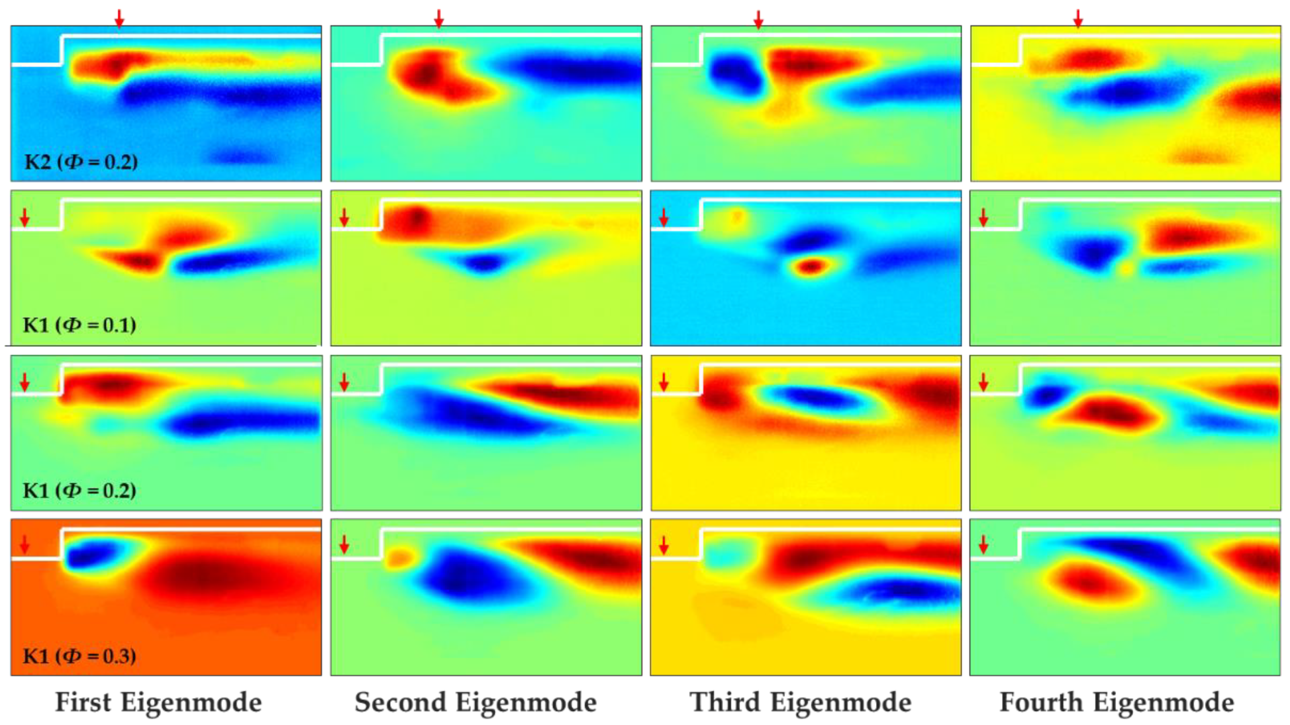
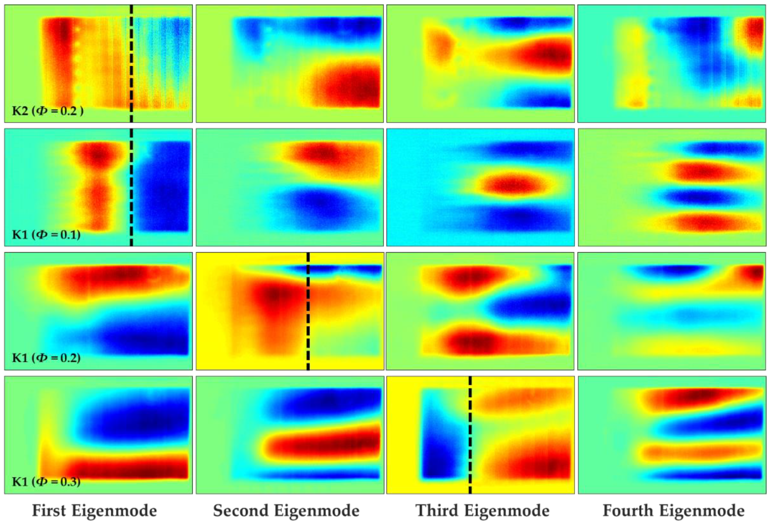
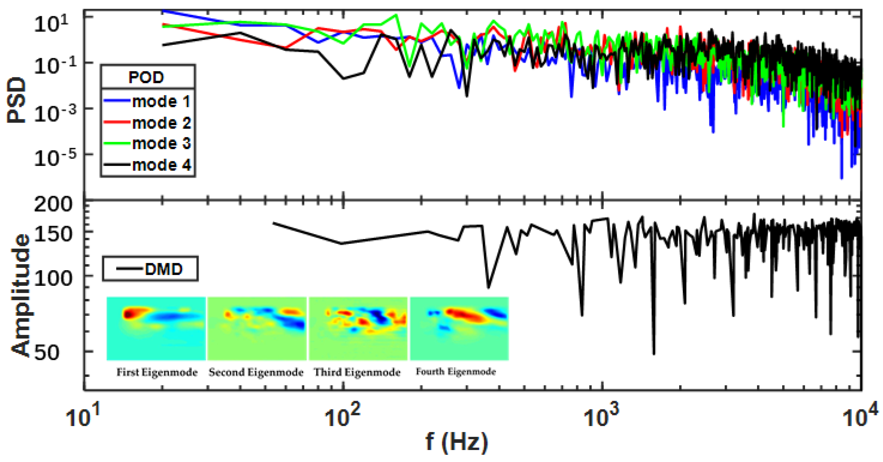
3.2. POD and DMD Analyses

POD and DMD analyses have been successfully applied in both experimental and numerical studies and have been used to assess the dynamic behavior of flame structures and combustion instability [11,12,36,37,38,39]. In the present study, the combustion characteristics under various conditions were investigated based on time-resolved flame chemiluminescence data. Specifically, sequential images of flame chemiluminescence were decomposed into the summation of POD and DMD modes. The characteristic frequencies that appeared during combustion were processed using the fast Fourier transform (FFT) for POD modes. The POD modes were ordered based on relative energy and low-rank POD modes occupied a majority of the overall energy. In contrast, the characteristic frequencies of the DMD modes were dependent on the eigenvalues.
Figure 5 and Figure 6 present the first four POD modes for FBE1 and FBE2, respectively. The 0th POD mode was identical to the mean flame structure shown in Figure 2, while the subsequent modes represented overlying fluctuations. The data in Figure 5 demonstrate that, for the four conditions in the present research, the first eigenmode was associated with fluctuations inside the cavity and within the shear layer, although the exact mode shapes were quite different for different operating conditions. The fuel jets and corresponding flow fields were the primary causes of these differences. In the case of the K2 injector, although there was only a single oblique shock near the leading edge caused by heat release, the flow field after the strong shock was relatively stable because of the high heat release rate. In addition, the separation of coherent structures at the injector is evident for modes 2 and 3. During trials using the K1 injector, the intensity variations of the two oblique shocks from fuel injection and heat release had an apparent effect on the flame structures. As noted above, the intensities of both shocks were proportional to the equivalence ratio and so, for Φ = 0.1, the intensity of the induced shocks was so weak that the corresponding flow field after the shocks was unsteady and the mixing effect was minimal; therefore, the POD mode distribution was distorted and some unexpected small individual regions emerged, confirming that the spatial position of the flame fluctuated greatly. In contrast, the POD modes became more regular with increases in the equivalence ratio (i.e., for Φ = 0.2 and 0.3), leading to stable, coherent flame structures.
A similar effect was also observed in the POD modes obtained from FBE2. In Figure 6, the distribution is seen to have separated structures along the mainstream flow direction (as indicated by the black dotted lines) in conjunction with the first mode at Φ = 0.2 using K2 and Φ = 0.1 using K1. In contrast, increasing Φ to 0.2 and 0.3 with the K1 injector induced the separated structures along the mainstream flow direction appearing in the second and third modes, respectively. With the reduced effect of the shock waves (i.e., Φ = 0.2 for K2 and Φ = 0.1 for K1), the flow and flame stabilization characteristics inside the cavity became closer to those previously reported for a non-reactive supersonic crossflow over a cavity [34]. At a relatively large length-to-depth ratio, this crossflow was found to exhibit two recirculation zones, one of which was located near the leading edge inside the cavity while the other was situated near the ramp as performed in [34] and summarized by Ben-Yakar et al. [17].
Figure 7 shows the FFTs of the primary POD modes and the DMD power spectrum for hydrogen injected from the K1 injector with Φ = 0.3. No dominant frequency and coherent structures are observed from the PSD and DMD mode distributions. The frequency spectra exhibit a broad distribution. Similarly, the other three cases investigated in this work did not generate a dominant frequency, suggesting that any periodic vortex shedding or acoustic modes did not couple with the reaction. The results are also consistent with the cavity surface pressure measurements in our previous works [29,40]. Conversely, the dominant frequencies associated with supersonic combustion generally appear in cavities with low length-to-depth ratios, as shown in Table 3, and are concentrated in the frequency range of 5–500 Hz [11,12,18,20,21,22]. A few studies have also found higher frequency oscillations in the kHz range [12,23], which were primarily attributed to the so-called thermal choke.
Based on the analyses in Section 3.1 and Section 3.2, it is apparent that a cavity flame holder with a length-to-depth ratio of 11 provides advantages in flame stabilization. Specifically, the flame was stabilized inside the cavity over a wide range of equivalence ratios (i.e., 0.1–0.3), indicating that the flame was more stable because the direct impact of inflow variations was much weaker compared with a flame stabilized in the cavity shear layer and jet wake. In addition, designs for thermal protection would be simplified with this arrangement because of the fixed location of the flame, and the probability of combustor damage from pressure fluctuations resulting from flame position variations would be much lower; however, it is worth noting that, although the flame was fixed inside the cavity, the location of the intense heat release zone might fluctuate within the flame zone, especially for a cavity with a large length-to-depth ratio, as is discussed in the following section.

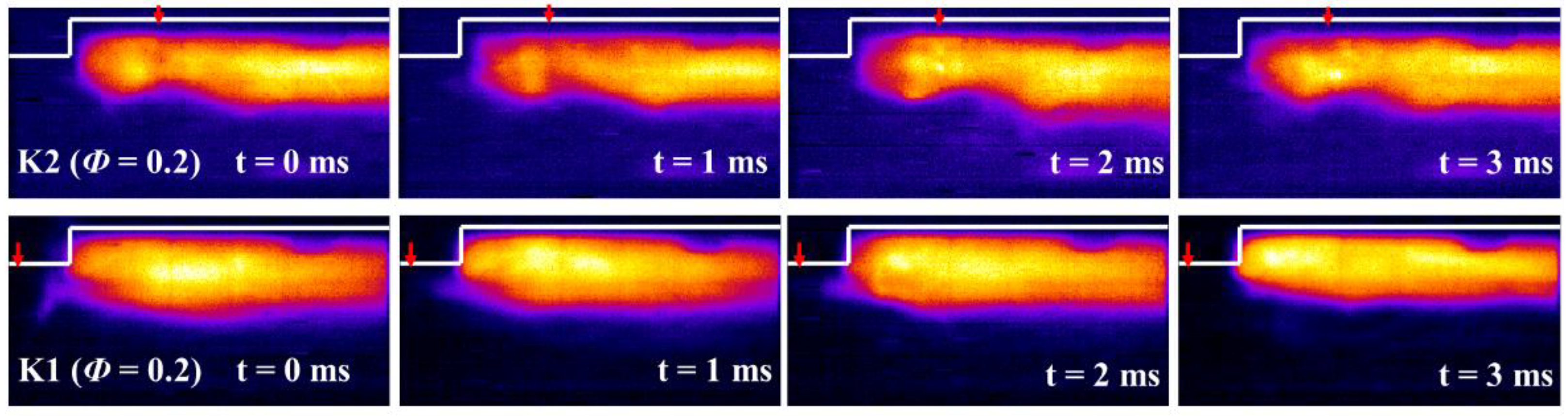
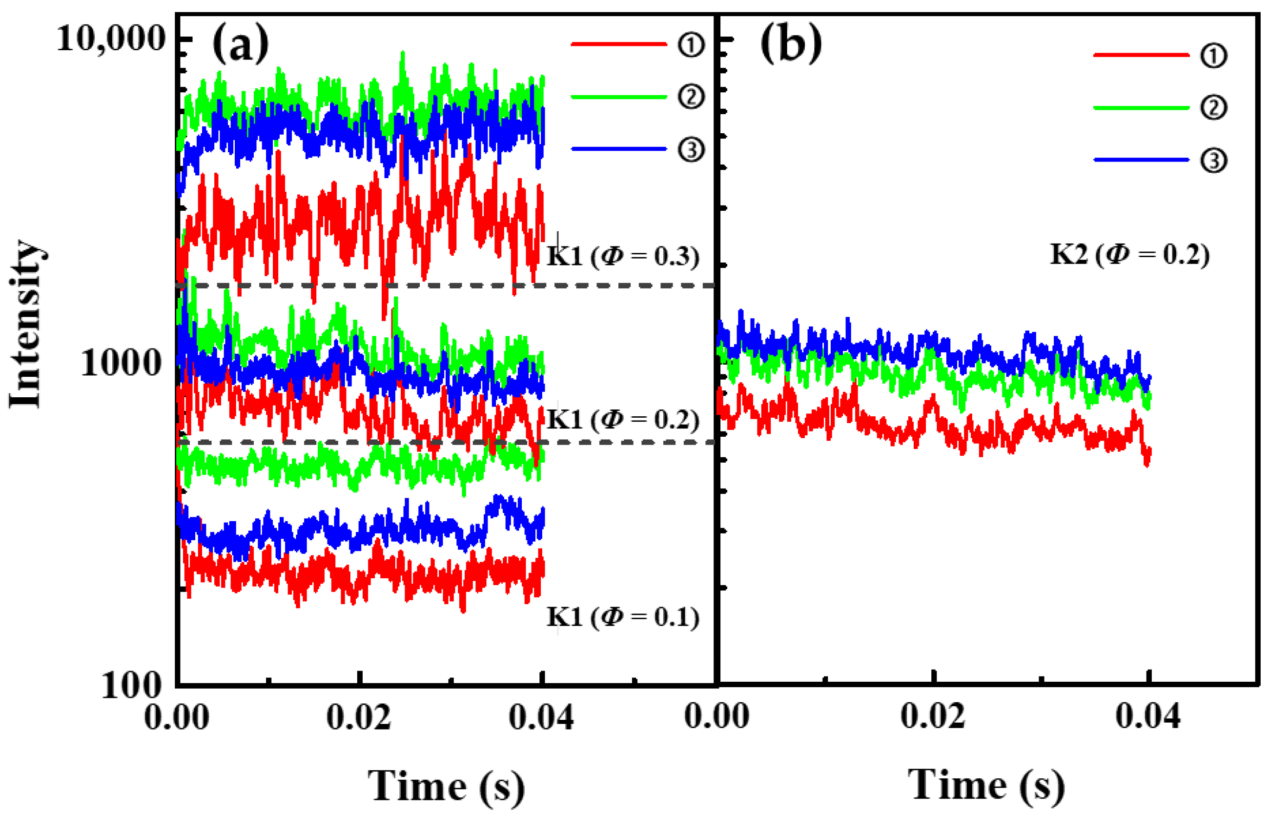
3.3. Temporally Resolved Flame Dynamics

The temporal variations of the flame demonstrated the instantaneous fluctuations of both the flame structure and intensity and Figure 8 summarizes the changes in the flames obtained using the K1 and K2 injectors for Φ = 0.2 obtained from FBE1. Interestingly, these two sequences of images show completely different structures. In the case of the K1 injector, the shear layer was relatively smooth, whereas the K2 injector generated a highly distorted shear layer and the effect of the jet on the flame structure was remarkable. As an example, a recirculation zone was formed near the leading edge of the cavity upstream of the K2 injector. This leading edge functioned as a step and was followed by transverse injection that created a large recirculation area with hot gases serving as a continuous ignition source [17].
To further illustrate the distribution pattern of the intense reaction and the effects of the fuel jets on the combustion characteristics of the cavity-based scramjet combustor, the mean intensity values for specific regions were calculated. In this process, the cavity was divided into three regions according to the FOV of FBE1, as shown in Figure 9.
The averaged chemiluminescence intensity was calculated by summing the intensity of each region and then dividing by the flame area in that region to exclude the effect of flame area variation. It is considered significant that regions ① and ② exhibited the highest mean intensity values in conjunction with the K2 and K1 injectors, respectively, as shown in Figure 10. This result suggests that a relatively long distance was required for the mixture of fuel and air to achieve optimal combustion. In addition, the location of the highest mean intensity was closer to the upstream position when using the K1 injector as compared with the K2. This result indicates that better mixing and a more suitable flow field possibly resulted from shock waves induced by the fuel jet from the K1 injector and from heat release.
The relative magnitudes of the heat release rates in the three regions remained unchanged over time for all four cases in the present research, confirming that fluctuations in the location of the intense heat release zone inside the cavity can be excluded from the design considerations for cavity-based supersonic combustors with large length-to-depth ratios.

4. Conclusions

The combustion characteristics of a cavity-based supersonic combustor with a large length-to-depth ratio of 11 were experimentally assessed, and the combustion inside the cavity exhibited specific behaviors. The flame was determined to be stabilized inside the cavity over a wide range of equivalence ratios, and the oblique shocks induced by fuel injection upstream of the cavity and heat release were found to play an important role in flame stabilization. The vertical injection of fuel from upstream of the cavity and relatively high equivalence ratios enhanced flame stabilization and promoted combustion. Compared with cavity-based combustors with low length-to-depth ratios, the present configuration was found to be advantageous in terms of suppressing combustion instability. Further studies visualizing the flow field while simultaneously acquiring flame images would provide a better understanding of the flame stabilization process.

Author Contributions

Conceptualization, Q.L. and S.C.; methodology, Q.L. and S.C.; software, X.L.; validation, X.L., X.Z. and L.C.; formal analysis, Y.T.; investigation, X.L., Q.L. and X.Z.; resources, Y.T.; data curation, Q.Z.; writing—original draft preparation, X.L.; writing—review and editing, Q.L.; visualization, X.Z.; supervision, W.F.; project administration, Q.L. and S.C.; funding acquisition, Q.L. All authors have read and agreed to the published version of the manuscript.

Funding

This research was funded by the National Natural Science Foundation of China (contractor No. 91741108 and No. 51876179 and No. J2019-I-0003-0004).

Institutional Review Board Statement

Not applicable.

Informed Consent Statement

Not applicable.

Data Availability Statement

Not applicable.

Acknowledgments

We thank Yeqing Chi for his help in the experiments.

Conflicts of Interest

The authors declare no conflict of interest. The funders had no role in the design of the study; in the collection, analyses, or interpretation of data; in the writing of the manuscript, or in the decision to publish the results.

References

  1. Yang, L.; Li, X.; Liang, J.; Yu, Y.; Yu, X. Laser-Induced Plasma Ignition of Hydrocarbon Fuel in Supersonic Flows. In Proceedings of the 20th AIAA International Space Planes and Hypersonic Systems and Technologies Conference, Glasgow, UK, 6–9 July 2015. [Google Scholar]
  2. Tian, Y.; Yang, S.; Le, J. Study on flame stabilization of a hydrogen and kerosene fueled combustor. Aerosp. Sci. Technol. 2016, 59, 183–188. [Google Scholar] [CrossRef]
  3. Huang, W. Transverse jet in supersonic crossflows. Aerosp. Sci. Technol. 2016, 50, 183–195. [Google Scholar] [CrossRef]
  4. Rabadan Santana, E.; Weigand, B. Effect of the reaction mechanism on the numerical prediction of the performance of a scramjet combustor at cruise flight 8 Mach number. Aerosp. Sci. Technol. 2021, 112, 106595. [Google Scholar] [CrossRef]
  5. Huellmantel, L.W.; Ziemer, R.W.; Cambel, A.B. Stabilization of Premixed Propane-Air Flames in Recessed Ducts. J. Jet Propuls. 1957, 27, 31–34. [Google Scholar] [CrossRef]
  6. Rasmussen, C.C.; Dhanuka, S.K.; Driscoll, J.F. Visualization of flameholding mechanisms in a supersonic combustor using PLIF. Proc. Combust. Inst. 2007, 31, 2505–2512. [Google Scholar] [CrossRef]
  7. Yuan, Y.; Zhang, T.; Yao, W.; Fan, X.; Zhang, P. Characterization of flame stabilization modes in an ethylene-fueled supersonic combustor using time-resolved CH* chemiluminescence. Proc. Combust. Inst. 2017, 36, 2919–2925. [Google Scholar] [CrossRef] [Green Version]
  8. Qin, F.; Huang, Z.-W.; He, G.-Q.; Wang, S.; Wei, X.-G.; Liu, B. Flame stabilization mechanism study in a hydrogen-fueled model supersonic combustor under different air inflow conditions. Int. J. Hydrog. Energ. 2017, 42, 21360–21370. [Google Scholar] [CrossRef]
  9. Liu, C.; Sun, M.; Wang, H.; Yang, L.; An, B.; Pan, Y. Ignition and flame stabilization characteristics in an ethylene-fueled scramjet combustor. Aerosp. Sci. Technol. 2020, 106, 106186. [Google Scholar] [CrossRef]
  10. Yuan, Y.; Zhang, T.; Yao, W.; Fan, X. Study on Flame Stabilization in a Dual-Mode Combustor Using Optical Measurements. J. Propuls. Power 2015, 31, 1524–1531. [Google Scholar] [CrossRef] [Green Version]
  11. Nakaya, S.; Kinoshita, R.; Lee, J.; Ishikawa, H.; Tsue, M. Analysis of supersonic combustion characteristics of ethylene/methane fuel mixture on high-speed measurements of CH* chemiluminescence. Proc. Combust. Inst. 2019, 37, 3749–3756. [Google Scholar] [CrossRef]
  12. Nakaya, S.; Yamana, H.; Tsue, M. Experimental investigation of ethylene/air combustion instability in a model scramjet combustor using image-based methods. Proc. Combust. Inst. 2021, 38, 3869–3880. [Google Scholar] [CrossRef]
  13. Huang, W.; Wang, Z.-G.; Pourkashanian, M.; Ma, L.; Ingham, D.B.; Luo, S.-B.; Lei, J.; Liu, J. Numerical investigation on the shock wave transition in a three-dimensional scramjet isolator. Acta Astronaut. 2011, 68, 1669–1675. [Google Scholar] [CrossRef]
  14. Huang, W.; Yan, L.; Tan, J.-G. Survey on the mode transition technique in combined cycle propulsion systems. Aerosp. Sci. Technol. 2014, 39, 685–691. [Google Scholar] [CrossRef]
  15. Huang, W.; Li, L.-Q.; Yan, L.; Liao, L. Numerical exploration of mixing and combustion in a dual-mode combustor with backward-facing steps. Acta Astronaut. 2016, 127, 572–578. [Google Scholar] [CrossRef] [Green Version]
  16. Gerlinger, P.; Stoll, P.; Kindler, M.; Schneider, F.; Aigner, M. Numerical investigation of mixing and combustion enhancement in supersonic combustors by strut induced streamwise vorticity. Aerosp. Sci. Technol. 2008, 12, 159–168. [Google Scholar] [CrossRef] [Green Version]
  17. Ben-Yakar, A.; Hanson, R.K. Cavity Flame-Holders for Ignition and Flame Stabilization in Scramjets: An Overview. J. Propuls. Power 2001, 17, 869–877. [Google Scholar] [CrossRef]
  18. Ma, F.; Li, J.; Yang, V.; Lin, K.-C.; Jackson, T. Thermoacoustic Flow Instability in a Scramjet Combustor. In Proceedings of the 41st AIAA/ASME/SAE/ASEE Joint Propulsion Conference & Exhibit, Tucson, AZ, USA, 10–13 July 2005. [Google Scholar]
  19. Wang, Z.-G.; Sun, M.-B.; Wang, H.-B.; Yu, J.-F.; Liang, J.-H.; Zhuang, F.-C. Mixing-related low frequency oscillation of combustion in an ethylene-fueled supersonic combustor. Proc. Combust. Inst. 2015, 35, 2137–2144. [Google Scholar] [CrossRef]
  20. Allison, P.M.; Frederickson, K.; Kirik, J.; Rockwell, R.D.; Lempert, W.R.; Sutton, J. Investigation of supersonic combustion dynamics via 50 kHz CH* chemiluminescence imaging. Proc. Combust. Inst. 2017, 36, 2849–2856. [Google Scholar] [CrossRef]
  21. Micka, D.J.; Driscoll, J.F. Combustion characteristics of a dual-mode scramjet combustor with cavity flameholder. Proc. Combust. Inst. 2009, 32, 2397–2404. [Google Scholar] [CrossRef]
  22. Lin, K.-C.; Jackson, K.; Behdadnia, R.; Jackson, T.A.; Ma, F.; Yang, V. Acoustic Characterization of an Ethylene-Fueled Scramjet Combustor with a Cavity Flameholder. J. Propuls. Power 2010, 26, 1161–1170. [Google Scholar] [CrossRef] [Green Version]
  23. Wang, H.; Wang, Z.; Sun, M. Experimental study of oscillations in a scramjet combustor with cavity flameholders. Exp. Therm. Fluid Sci. 2013, 45, 259–263. [Google Scholar] [CrossRef]
  24. Ouyang, H.; Liu, W.; Sun, M. Parametric study of combustion oscillation in a single-side expansion scramjet combustor. Acta Astronaut. 2016, 127, 603–613. [Google Scholar] [CrossRef]
  25. Ouyang, H.; Liu, W.; Sun, M. The influence of cavity parameters on the combustion oscillation in a single-side expansion scramjet combustor. Acta Astronaut. 2017, 137, 52–59. [Google Scholar] [CrossRef]
  26. Benyakar, A.; Mungal, M.G.; Hanson, R.K. Time evolution and mixing characteristics of hydrogen and ethylene transverse jets in supersonic crossflows. Phys. Fluids 2006, 18, 026101. [Google Scholar] [CrossRef] [Green Version]
  27. Choi, J.-Y.; Ma, F.; Yang, V. Combustion oscillations in a scramjet engine combustor with transverse fuel injection. Proc. Combust. Inst. 2005, 30, 2851–2858. [Google Scholar] [CrossRef]
  28. Li, F.; Sun, M.; Cai, Z.; Sun, Y.; Li, F.; Zhang, J.; Zhu, J. Experimental study of flame stabilization in a single-side expansion scramjet combustor with different cavity length-to-depth ratios. Acta Astronaut. 2020, 173, 1–8. [Google Scholar] [CrossRef]
  29. Tian, Y.; Zeng, X.; Yang, S.; Zhong, F.; Le, J. Experimental study on the effect of equivalence ratio and injector position on flow structure and flame development in the scramjet combustor. Aerosp. Sci. Technol. 2018, 82–83, 9–19. [Google Scholar] [CrossRef]
  30. Xiong, P.; Zheng, D.; Tan, Y.; Tian, Y.; Le, J. Experimental study of ignition and combustion characteristics of ethylene in cavity-based supersonic combustor at low stagnation temperature and pressure. Aerosp. Sci. Technol. 2021, 109, 106414. [Google Scholar] [CrossRef]
  31. Tian, Y.; Yang, S.; Le, J.; Zhong, F.; Tian, X. Investigation of combustion process of a kerosene fueled combustor with air throttling. Combust. Flame 2017, 179, 74–85. [Google Scholar] [CrossRef]
  32. Schefer, R.; Kulatilaka, W.; Patterson, B.; Settersten, T. Visible emission of hydrogen flames. Combust. Flame 2009, 156, 1234–1241. [Google Scholar] [CrossRef] [Green Version]
  33. Ballester, J.; Hernandez, R.; Sanz, A.; Smolarz, A.; Barroso, J.; Pina, A. Chemiluminescence monitoring in premixed flames of natural gas and its blends with hydrogen. Proc. Combust. Inst. 2009, 32, 2983–2991. [Google Scholar] [CrossRef]
  34. Zhong, F.; Le, J.; Tian, Y.; Yue, M. Investigation of the combustion process in an ethylene-fueled scramjet combustor. J. Exp. Fluid Mech. 2021, 35, 34–43. [Google Scholar] [CrossRef]
  35. Wang, H.; Wang, Z.; Sun, M.; Wu, H. Combustion modes of hydrogen jet combustion in a cavity-based supersonic combustor. Int. J. Hydrog. Energy 2013, 38, 12078–12089. [Google Scholar] [CrossRef]
  36. Zebiri, B.; Piquet, A.; Hadjadj, A. Analysis of shock-wave unsteadiness in conical supersonic nozzles. Aerosp. Sci. Technol. 2020, 105, 106060. [Google Scholar] [CrossRef]
  37. Pavalavanni, P.K.; Sohn, C.H.; Lee, B.J.; Choi, J.-Y. Revisiting unsteady shock-induced combustion with modern analysis techniques. Proc. Combust. Inst. 2019, 37, 3637–3644. [Google Scholar] [CrossRef]
  38. Markovich, D.M.; Abdurakipov, S.S.; Chikishev, L.M.; Dulin, V.M.; Hanjalić, K. Comparative analysis of low- and high-swirl confined flames and jets by proper orthogonal and dynamic mode decompositions. Phys Fluids 2014, 26, 065109. [Google Scholar] [CrossRef]
  39. Kumar, R.; Massa, L. Dynamic Mode Decomposition Analysis of Detonation Waves. In Proceedings of the 42nd AIAA Fluid Dynamics Conference and Exhibit, New Orleans, LA, USA, 25–28 June 2012. [Google Scholar]
  40. Tian, Y.; Shi, W.; Guo, M.; Liu, Y.; Zhang, C.; Le, J. Investigation of combustion characteristics in a hydrogen-fueled scramjet combustor. Acta Astronaut. 2021, 186, 486–495. [Google Scholar] [CrossRef]
Figure 1. (a) Schematic of the combustor; (b) schematic of the measurement system.
Aerospace 09 00214 g001
Figure 2. Instantaneous, averaged and standard deviation images of flame chemiluminescence.
Aerospace 09 00214 g002
Figure 3. (a) Averaged flame brush; (b) the outermost edge of standard deviation images.
Aerospace 09 00214 g003
Figure 4. Overall intensity of flame chemiluminescence in different cases.
Aerospace 09 00214 g004
Figure 5. The first four POD modes of chemiluminescence images captured by FBE1.
Aerospace 09 00214 g005
Figure 6. The first four POD modes of chemiluminescence images captured by FBE2.
Aerospace 09 00214 g006
Figure 7. Power spectrum density of FFT for POD mode coefficients, power spectrum of DMD modes for hydrogen injected from K1 injector under Φ = 0.3 together with the first four DMD modes of chemiluminescence images captured by FBE1.
Aerospace 09 00214 g007
Figure 8. The temporal variation of flame chemiluminescence in K1 and K2 injector cases, Φ = 0.2.
Aerospace 09 00214 g008
Figure 9. Schematic of the three regions.
Aerospace 09 00214 g009
Figure 10. Averaged chemiluminescence intensity in different regions of the cavity with (a) the K1 injector and (b) the K2 injector.
Aerospace 09 00214 g010
Table 1. The experimental parameters used in the present study.
CaseInjectorInjection Pressure (MPa)Equivalence
Ration(Φ)
1K20.30.2
2K10.150.1
3K10.30.2
4K10.40.3
Table 2. Flame stabilization modes previously investigated and reported in the literature.
AuthorsFuelMach NumberL/DOperating
Conditions
Flame Stabilization Mode
Yuan et al. [10]Ethylene2.54Φ = 0.258
Φ = 0.291
Φ = 0.376
Φ = 0.411
Inside the cavity
In the cavity shear layer
Oscillation
In the jet wake
Nakaya et al. [11]Ethylene25Φ = 0.070
Φ = 0.076
Φ = 0.150
In the cavity shear layer
Oscillation
In the jet wake
Micka and Driscoll [21]Hydrogen2.24T0 = 1000–1100 K
T0 = 1000–1300 K
T0 > 1350 K
Inside the cavity
Oscillation
In the jet wake
Wang et al. [35]Hydrogen2.524, 7T0 = 1486 KIn the jet wake
Inside the cavity/
In cavity shear layer
Table 3. The oscillation characteristics reported in the literature.
AuthorsFuelMach NumberL/DDominant
Frequency
Comment
Choi et al. [27]Hydrogen34None
Lin et al. [22]Ethylene2.23.9100–400 HZThe upper bound is dictated by the shock-flame coupling mechanism and the lower bound by the injector–flame interaction.
Allision et al. [20]Ethylene25.9340 HZAn instability in which acoustic waves are reflected and convected between the shock train and flame front.
Micka and Driscoll [21]Hydrogen2.245–20 HZThe frequency of the oscillation between the modes.
Wang et al. [23]Hydrogen 715–20 kHzBoth the frequency and intensity of the pressure oscillations shift to higher levels compared to cold flow.
Ouyang et al. [25]Ethylene2.14, 5, 740–140 HzThe dominant frequency fluctuates slightly with the variation of the length to depth ratios.
Nakaya et al. [11]Hydrogen
/Ethylene
25Low: 50–500 Hz
High: kHz
The dominant frequency increased with increasing equivalence ratio.
Publisher’s Note: MDPI stays neutral with regard to jurisdictional claims in published maps and institutional affiliations.

