Article

Investigation of Improvement Design on Aileron Surface Flow State of High Lift Configuration in BWB

1
School of Aeronautics, Northwestern Polytechnical University, Xi’an 710072, China
2
School of Aerospace Engineering, Tsinghua University, Beijing 100084, China
*
Author to whom correspondence should be addressed.
Aerospace 2022, 9(12), 842; https://doi.org/10.3390/aerospace9120842
Submission received: 6 October 2022 / Revised: 30 November 2022 / Accepted: 13 December 2022 / Published: 17 December 2022
(This article belongs to the Special Issue Aerodynamics Design)

Abstract

:
The aileron is one of the most important tools for adjusting the roll attitude of the aircraft, but the surface flow state of the aileron is likely to be affected by high-lift devices. In this paper, by using computational fluid dynamics (CFD) simulations and wind tunnel tests, the Krueger flap effects on the surface flow state of ailerons in a typical blended wing body civil aircraft were investigated. In order to increase the lift, deflecting the Krueger flap makes the flow separation occur on the aileron surface of BWB civil aircraft. This way of the surface stall that the flow separation in the aileron zone first appears at the wing tip rather than at the wing root is unreasonable for civil aircraft. For the above problem, a sensitivity analysis of the design parameters of the Krueger flaps was carried out. The results indicate that the angle of the outboard Krueger flap mainly affects the flow separation of the ailerons. Its length affects the pitch moment tremendously, while its width slot affects the pitch moment slightly. Finally, the design principles of the BWB Krueger flap for the improvement aileron surface flow state were proposed, and the redesign of the BWB high lift configuration significantly improved the flow state of the aileron zone at a minimal cost of aerodynamic characteristics without losing the existing great aerodynamic performance.

1. Introduction

The roll attitude control of most aircraft depends on the ailerons [1], so the flow state on the aileron surfaces must be great within the entire flight envelope. Flow separation first appears at the leading edge of the wing root and then gradually extends to the wing tip to ensure the attached flow on the aileron area as much as possible during the cruising, take-off, and landing process. Take-off and landing characteristics are critical to the aerodynamic performance of the aircraft. When the airplane is taking off and landing, the flight speed is relatively low compared to that in the cruise condition. Therefore, the high-lift device is required to produce sufficient lift for the aircraft [2]. However, the high lift device changes the lift distribution and surface flow condition of the clean configuration wing. Especially the high lift device in the leading edge of the wing may lead to the flow separation that develops from the wing tip to the wing root in the stall echelon of the wing [3]. The clean configuration refers to the configuration in which the entire wing is smooth and intact, and the booster and airbrakes are not opened. Finally, the surface of the ailerons is covered by the separation flow. For the stability design of civil aircraft, this should be avoided. With the rapid development of the global civil aviation industry, the frequency of take-off and landing of civil aircraft worldwide is increasing. In order to shorten the take-off and landing time, higher requirements are placed on the performance of the aircraft’s high-lift device [4]. Nevertheless, the higher requirements for lift characteristics make the hidden danger of stalling more serious, which occurs in the aileron zone first. Therefore, it is important to pay great attention to investigating the aileron surface flow state of high lift configuration.
The BWB is the most promising candidate for the next generation of transport to achieve “green aviation”. Research on BWB layout aircraft has been carried out in the field of UAV (unmanned aerial vehicle) and civil aircraft [5,6]. However, due to the particularity of its aerodynamic layout, there are some challenges that have not been solved yet [7,8]. For example, the design technology and method of traditional high-lift devices with leading-edge slats and trailing-edge slotted flaps as the mainstream are relatively perfect [9,10]. Due to its unique blended geometric characteristics, the low-speed characteristics of BWB can hardly gain enough lift under trimmed conditions by applying the traditional high-lift device. The slotted bull-nose Krueger flap is applied to improve the low-speed stall characteristics of the BWB configuration. This kind of high-lift device is suitable for relieving the pressure of trim and realizing sufficient lift gain.
The aerodynamic characteristics of the clean configuration of BWB were studied by Yu Gang [11]. According to the characteristics of the aerodynamic layout of the BWB, based on the clean configuration, the high lift device suitable for the BWB is designed, including the leading edge Krueger flaps and the trailing edge simple flaps. In addition, ailerons are also designed. There is a big difference between the BWB and the current mainstream civil aircraft for high lift devices because of two main reasons for this: on the one hand, the trimming efficiency of the traditional high lift device with a three-stage trailing edge in BWB is not as good as that of traditional civil aircraft because the BWB aircraft has a shorter pitch control arm of force. On the other hand, with the improvement of industrial manufacturing technology, natural laminar flow technology is widely studied and considered to be an extremely effective drag-reduction approach [12,13]. Many research projects in Europe and the United States, such as ACFA2020/ERA, have clearly stated that the wings of their BWB layout aircraft adopt hybrid/natural laminar flow technology [14,15], as the BWB layout is an advanced layout of future civil aircraft. However, leading-edge slats are not suitable for the use of laminar flow technology as they inevitably destroy the continuity of the upper surface of the wing [16,17]. Therefore, the slotted bull-nose Krueger flap was applied to the BWB.
Krueger flap, proposed in 1947 [18], has a unique form of kinematic mechanism, which can avoid breaking the continuity on the leading edge and the upper surface of the airfoil. It also has fewer design constraints than traditional slats. In 1970, Boeing implemented the variable-camber Krueger flap design, but it was subsequently discontinued due to the complexity of the mechanism and the expensive manufacturing and maintenance costs [19]. At this point, the development of Krueger flaps stalled until the concept of BWB layout aircraft and laminar flow technology emerged. Akaydin’s research shows that the Krueger flap can achieve the lift-enhancing effect of slats with different deflections through changes in geometry and slat parameters of the Krueger flap [20,21]. Vicroy designed a folding blunt Krueger flap based on the ERA BWB layout aircraft and carried out low-speed experiments with satisfactory design results [22]. The airframe of traditional civil aircraft is basically a slender body whose flow has little effect on the spanwise flow of the wing airflow. However, the sweep angle of the central body of the BWB layout is large, which induces the spanwise flow on the wing surface of the clean configuration. Therefore, to eliminate this adverse effect on the wing and improve the flow state of the wing surface at large angles of attack, Kruger flaps are designed to start from the location of the blended wing body to the wing tip. The effect of the spanwise flow introduced by the central body on the wing is suppressed by the flow control of the Kruger flaps. At the same time, the BWB using the design of the Krueger flap also achieved great aerodynamic characteristics. However, there is a strong spanwise flow with a tendency for the flow to separate in the aileron zone at the large angles of attack when the flow state of the location of the blended of the wing and the airframe is still very good. This phenomenon is quite different from the clean configuration.
As mentioned above, the first flow separation in the aileron zone must also be avoided. However, the lift and moment characteristic of the aircraft will be lost inevitably if the safety of the aircraft is pursued excessively. The difficulty of this paper is that the contradiction between the great aerodynamic characteristics of the aircraft and the aileron surface flow state is difficult to reconcile. This makes it difficult to quantify the design constraints, so it is unrealistic to use the aerodynamic optimization method to solve this problem. There have been many studies on the design of the high-lift device, but the design of the high-lift device for the BWB layout is not perfect. There is still a lack of theories with strong guiding significance, so the relevant mechanisms and design principles need to be studied. In the present study, experiments and numerical simulations are performed to investigate the aerodynamic characteristics of the high-lift configuration and analyze the flow mechanism leading to the spanwise flow on the aileron. Considering the flow state of the aileron zone and the aerodynamic characteristics of the aircraft, a sensitivity analysis of the design parameters of the Krueger flaps was carried out. The design significantly improved the flow state of the aileron zone at a minimal cost of aerodynamic characteristics without losing the existing great aerodynamic performance. Three key parameters of Krueger flap design were summarized for the improvement of Aileron surface flow. The design principles were also proposed to provide a reference for related designs.

2. Definition of the Configurations

The high lift configuration of BWB is the main research object in this paper, and the clean configuration is used as a reference. The clean configuration of BWB shown in Figure 1 consists of a central airframe, wing, vertical tail, and ventilated nacelles with supports. The high lift configuration of BWB shown in Figure 1 is defined as consisting of a central airframe, wing, vertical tail, Krueger flap with 30° deflection, inboard flap, outboard flap, inboard aileron with 0° deflection, outboard aileron with 0°deflection, and ventilated nacelles with supports. The problem studied in this paper focuses on the aileron area. It was verified that whether the nacelle has power or not has no effect on the flow state of the aileron area, so this paper selected the ventilated nacelle to reduce the calculation cost. It should be noted that the pivot position of the Krueger flap is specified at its trailing edge in Figure 1c to study the slot width and deflection angle separately. However, in the real state, the slot width and the deflection angle of the Krueger flap shown in Figure 2 move at the same time.

3. Computational Approach

3.1. Numerical Methods

The computations were performed with a structured CFD (computational fluid dynamics) code modified from CFL3D, which has been verified to be effective in predicting various complex flow structures [23,24]. For the simulations described here, the governing equations are the RANS (Reynold-averaged Navier–Stokes) equations. The finite volume method was applied to solve the RANS equations. The second-order upwind Roe-FDS (flux differences splitting) scheme was applied to discretize the inviscid spatial term, and the second-order central difference scheme was applied to discretize the viscous spatial. The fully turbulent flow was prescribed, and the SA (Spalart–Allmaras) model was used to model the turbulence effects. The time-stepping method was the AF (approximate factorization) implicit time-marching method. In this method, the momentum equations for the contravariant velocity components and the elliptic equation for the pressure are solved directly in the transformed space by applying the delta-form approximate factorization scheme and the Tschebyscheff method, respectively [25]. In order to accelerate convergence, the multi-grid method was applied. The multi-grid method is a general numerical technique for solving continuous problems such as boundary value problems or functional integral equations. There are many separate aspects and extensions of the method, and the study of multi-grid is an active area of numerical analysis research [26].
Multi-block structured grid is used for the configuration. In order to maintain grid consistency, the high lift configuration grid shown in Figure 3b was generated from the clean configuration grid shown in Figure 3a by adding the Krueger block from the flow field space of the clean configuration grid and filling the wing inner solid area grid for the inboard flap, outboard flap, inboard aileron, and outboard aileron. The grid far-field boundary distance was about 20 body lengths, and a characteristic inflow and outflow boundary condition was applied to it. All solid surfaces were set as the no-slip adiabatic wall. The symmetry boundary condition was used to generate only a half-model grid.

3.2. Grid Convergence Study

A grid convergence study was applied to ensure the reliability of the numerical solution. The high lift configuration was selected as the role of the grid convergence study because it is the main research object of this paper and the boundary conditions in the two configurations are the same. The high lift configuration was calculated using six levels of the grid at 0.15 Ma. The volume cell growth ratio was 1.5, from 8.53 million volume grids to 160.74 million volume grids. The aerodynamic forces coefficient results are shown in Figure 4, in which Grid_6 is the finest grid, Grid_1 is the coarsest grid, CL represents the lift coefficient, the CD represents the drag coefficient, and CM represents the pitch moment coefficient. The results indicated that when the number of volume cells was approximately 49.53 million, the grid (Grid_3) could be considered reliable. y+ was approximately 1; in the boundary layer, the size of two adjacent grid nodes’ growth rate was 1.15. Thus, Grid_3 was used in the later calculation.

4. Results and Discussion

4.1. Comparison of CFD Results with Wind Tunnel Data

The experiment was carried out by the FL-9 wind tunnel shown in Figure 5 at AVIC Aerodynaiviics Research Institute of China. The FL-9 wind tunnel is a low-speed supercharged wind tunnel. The test section is a rectangle with a size of 4.5 m × 3.5 m and a length of 10 m. The test Reynolds number is changed by adjusting the airflow pressure in the wind tunnel. The 9.5 MW AC variable frequency motor is driven to change the fan speed to achieve wind speed control. Under normal pressure, the maximum wind speed is 130 m/s. Therefore, the FL-9 wind tunnel fully meets the experimental requirements of BWB with the boundary condition, Mach number 0.15 and Reynolds number 6.29 × 10⁶. The experiment was carried out by the wind tunnel shown in Figure 5. This is also the boundary conditions of CFD results using the Grid_3. The wind tunnel experiment and CFD simulations were performed over the range of angles of attack from −4° to 18° with 2° intervals for clean configuration and the range of angles of attack from −4° to 24° with 2° intervals for high lift configuration. In order to alter the angle of attack, the test adopted the single strut abdominal support test system of the FL-9 wind tunnel. The upper end of the circular section ventilation strut was connected to the balance and the model, and the lower end was installed on the angle of attack mechanism to achieve the change in the model’s angle of attack. In order to measure the aerodynamic coefficient, a box strain balance, which has six components, was used. The main measuring principle of it is that the scale is mounted on a bracket, and the model is connected to the scale. The model is subjected to aerodynamic coefficients that distort the elastic elements of the balance. The resistance wire pasted onto the element is connected to the bridge. Component distortion causes the resistance wire to stretch, causing changes in resistance and voltage. The voltage signal is converted to digital output to reflect the aerodynamic change. Finally, the aerodynamic coefficients were obtained.
Figure 6 shows the aerodynamic coefficient curve results of computation and wind tunnel experiment for the clean configuration and the high lift configuration. In Figure 6, Alpha represents the angle of attack, Cal represents the computation result, Exp represents the experiment result, Clean represents the clean configuration, and High_Lift represents the high lift configuration. Figure 7 shows the surface flow of computation and experiment for the clean configuration. In Figure 7, Ma represents the Mach number. It can be seen from the aerodynamic coefficient curve results that the computation and test agree well with each other. Additionally, CFD simulates the starting position and development trend of flow separation in the experiment from the surface flow in Figure 7, which indicates that the flow separation phenomenon of the aircraft under a large angle of attack is captured greatly. Although there is a small difference between the CFD simulation and the experiment at higher angles of attack, the comparison of CFD results with wind tunnel data shows that the grid generation strategy and computation method used in this paper are reliable.
It should be noted that the aerodynamic characteristic was improved significantly in the large angle of attack with the application of a high lift device in Figure 6. Additionally, the capability of the high lift device of BWB has been so great that almost any modification can take a toll on the existing features, which is the difficulty of subsequent improvement design of aileron surface flow. How can the aileron surface flow of the aircraft be improved without losing the existing good aerodynamic characteristics of the aircraft? Figure 8 shows the entire investigation process of this paper.

4.2. Analysis of Aerodynamic Characteristics

In this section, the effects of the Krueger flap on the aileron surface flow state are investigated through analysis of the aerodynamic characteristics of the high lift configuration in real conditions. The pitching moment coefficient needs to be explained. First, through CFD calculation, the normal stress (Cp) and tangential stress (Cf) of each node on the body surface are obtained. Then, the two stresses are projected in three directions of the coordinate system. According to the principle of the finite volume method, just as we can see in Figure 9a, the forces (Fx, Fy, Fz) of the surface element in three directions are calculated. Therefore, the pitching moment value of the surface element is CMi = [(xE. − xM)Fz + (zE. − zM)Fx]. The pitching moment of the whole aircraft is CM = ∑CMi · Cp represents the pressure coefficient. Cf represents the friction coefficient. Fx, Fy, and Fz represent surface element forces of three directions in the coordinate system. CMi represents the surface element pitch moment coefficient. xE and xM represent the coordinate in the x direction of the element of the surface and the mass center. zE and zM represent the coordinate in the z direction of the element of the surface and the mass center. ∑ represents the sum of all surface elements of the whole aircraft. CM represents the pitch moment coefficient of the whole aircraft. It is worth noting that all calculations are dimensionless in CFL3D
The CL and CM curves are used as the evaluation criteria for the aerodynamic characteristics, which are shown in Figure 9. The surface streamlines state of the aileron zone is shown in Figure 10, which is used as the evaluation criteria for the stall state in the aileron region. The CFD numerical simulation results with Mach number 0.15 and Reynolds number 8.90 × 10⁷ are shown in Figure 9. It can be seen from the Figure that from −4° to 18°, the pitching moment coefficient decreases with the increase in the angle of attack and nonlinearity in the whole process. The pitch moment coefficient gradually decreases from the head-up moment (to make the aircraft raise its head) at a negative angle of attack to the head-down moment (to make the aircraft bow its head) at a positive angle of attack. The pitch moment coefficient reaches the minimum value at the 18° angle of attack. The aircraft loses its static stability characteristics in the pitch direction when the angle of attack is greater than 18°. After the angle of attack of 18°, the pitching moment coefficient increases rapidly, so the angle of minimum pitch moment value representing the longitudinal static stability characteristic is defined. In general, the longitudinal static stability characteristic of the high lift configuration of BWB is great.
Figure 10 shows the upper surface limiting streamlines and local pressure distribution contour of the high lift configuration. Cp represents the pressure coefficient. As shown in Figure 10a, it can be seen that when the angle of attack is 10°, the upper surface limiting streamlines of the central body and the wing are straight, without obvious spanwise flow, and the leading surface limiting streamline at the location of blend wing body is slightly biased towards the central body. The aileron streamlines are smooth without separation flow, and the streamlines are slightly deflected in the spanwise direction. Therefore, in general, the surface flow state of the aileron area is fine at the angle of attack of 10°. At the same time, a large area of flow separation is observed on the inboard and outboard flaps with a big area of low friction drag because of the Krueger angle reaching 30°, but the stall on the upper surface of the flaps has a little negative effect on the aircraft. The first stall in the flap area is in line with the general aircraft aerodynamic layout design. As shown in (c) of Figure 10, when the angle of attack is 18°, obvious spanwise flow is found at the location of the blend wing body and tends to expand outwards, but it is restrained by the flow on the upper surface of the wing induced by the Krueger flap, so the upper surface of the wing maintains a good flow state as a whole.
However, there is a separation flow with a relatively strong spanwise flow on the upper surface of the aileron of the high lift configuration (18°), as shown in Figure 10c, when the surface flow is good in most areas of the wing. According to the pressure distribution in Figure 10, the shape of the pressure distribution on the trailing edge of the wing changes very little from 10° to 18°angle of attack, but the negative pressure peak at the leading edge of the wing nearly doubled. The larger adverse pressure is the main reason for the separation flow at the trailing edge [27]. While the situation is reversed in the clean configuration with the same boundary conditions shown in Figure 11a, flow separation occurs first at the blend wing body at 8° when the surface flow on the upper aileron is good. It is not until a large area of flow separation occurs on the inside of the wing that the aileron generates a strong spanwise flow under the influence of the aircraft sweep angle. Although the flow separation on the upper surface of the aileron eventually occurs, as shown in Figure 11b, the separation at the wing root is earlier so that the aircraft can capture an obvious stall signal (lift drop) before the aileron is in hidden danger of control. In contrast, the Krueger flaps of high lift configuration increase lift at high angles of attack with the destruction of the flow state on the upper surface of the aileron zone, causing the aileron zone to stall first except for the leading of blend wing body when the BWB is in extreme flight conditions. However, it can be seen from Figure Figure 10c and Figure 11b that the effect of the spanwise flow introduced by the central body on the wing is suppressed by the flow control of the Kruger flaps.

4.3. Sensitivity Analysis for Design of Aileron Surface Flow State

This chapter only considers the improved design of Krueger flaps to ensure that the great high-speed aerodynamic characteristics of BWB are not affected. The Krueger flap geometry parameters have been studied in detail in Ref [3]. After investigation, it is found that the geometric parameters of Krueger flaps have little effect on the stall characteristics of the aileron region in three-dimensional conditions. After the analysis in the previous section, it can be seen that the large adverse pressure gradient on the upper wing is the main reason for the separation flow of the trailing edge of the aileron region. Additionally, the deflection angle of the Krueger flap has the most obvious control effect on the adverse pressure gradient on the wing. The smaller the Krueger flap deflection angle, the greater the adverse pressure gradient with the worse stall characteristic of the trailing edge of the wing. Conversely, if the deflection angle of the Krueger flap is too large, the airflow direction of the leading edge of the wing will be nearly tangent to the upper surface of the wing, which will cause the airflow to flow over the upper surface of the wing more gently. In this way, the acceleration flow is not obvious when the airflow flows through the leading edge of the wing with a small adverse pressure gradient and great stall characteristic of the trailing edge of the wing, but the local lift is greatly reduced. From the above analysis of the flow mechanism, it can be seen that there is a contradiction between the high lift effect of the Krueger flap and the stable stall state of the trailing edge of the wing. The purpose of this paper was to study how to ingeniously coordinate the above contradictions and eliminate the flow separation on the aileron surface without affecting the lift characteristics as much as possible.
The main function of the flap of the high lift configuration is to provide lift, and the requirements for the trailing edge stall are relatively low. The trailing edge stall of the aileron is required to be higher because the aileron must ensure that the up and down deflection of the rudder is effective at the same time. The function of flaps and ailerons determines that there are differences in their requirements for Krueger flaps. Therefore, a segmented design of the Krueger flap shown in Figure 12 is considered; the part close to the wing’s root needs a high lift, so the original Krueger configuration is retained. Additionally, the part close to the wingtip requires a good aileron flow state, so the Krueger flap deflection angle needs to be redesigned.

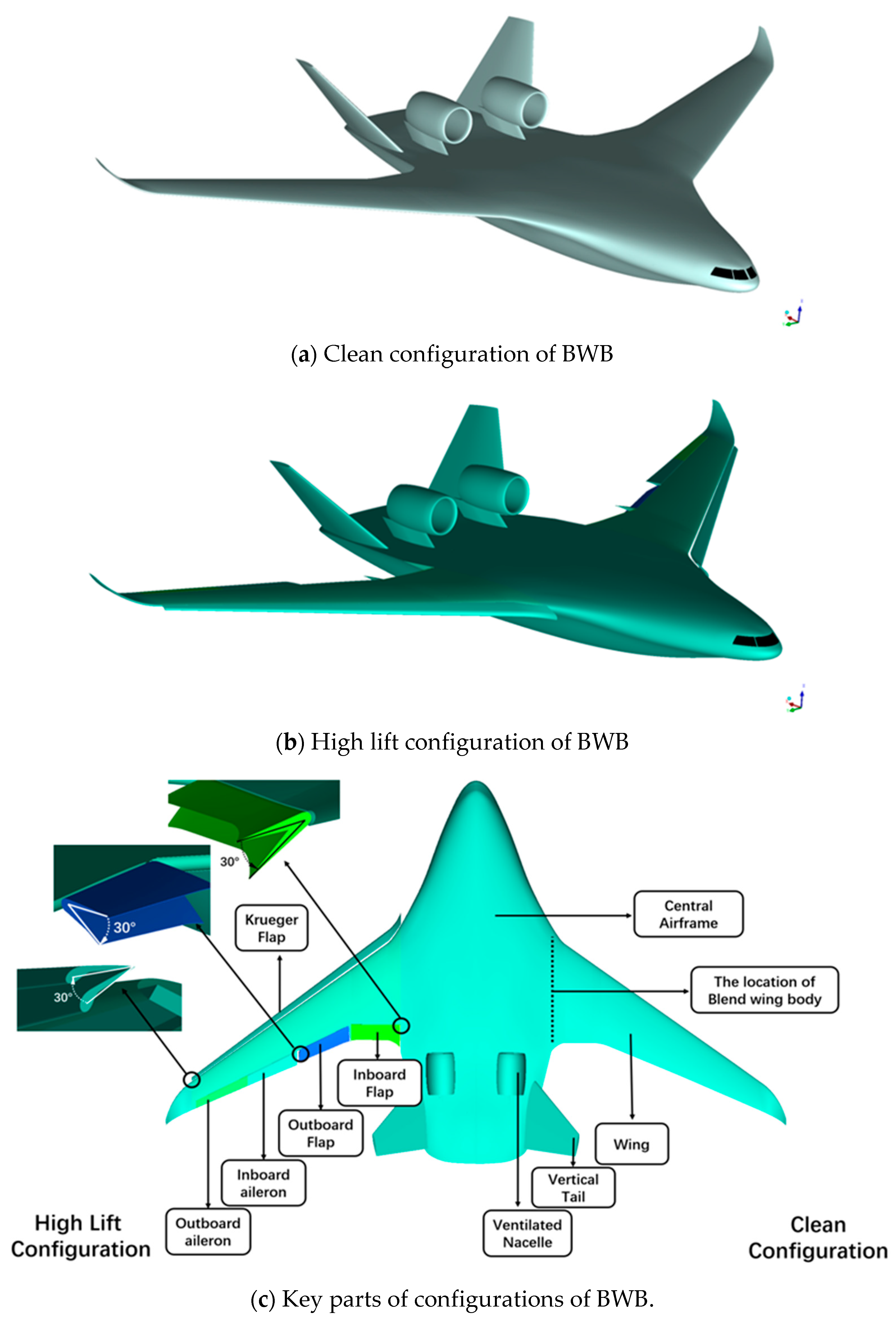
4.3.1. Sensitivity Analysis of Deflection Angles

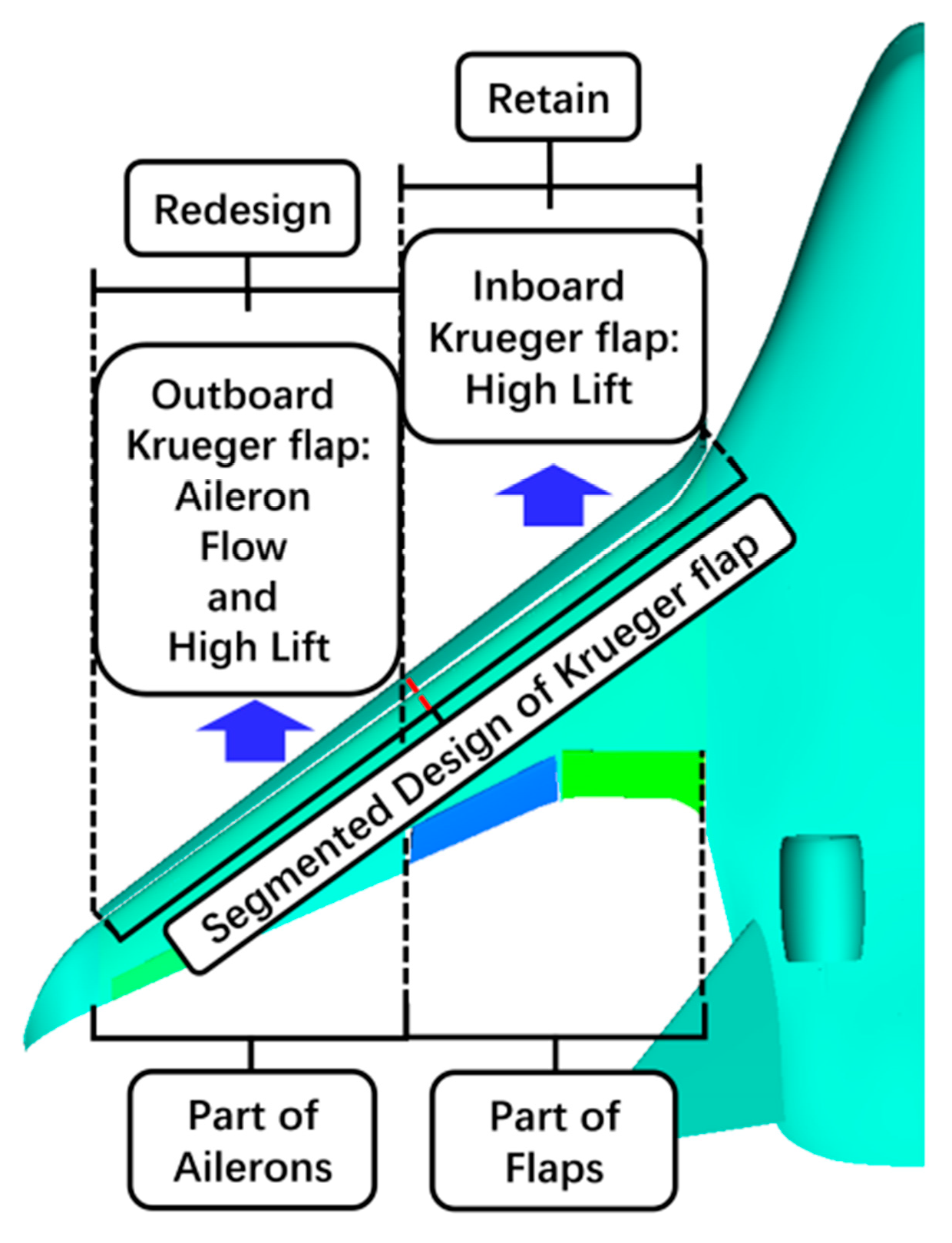
The Krueger flap deflection region is considered first. “Theta” is defined as the deflection angle of the Krueger flap. The straight line where the trailing edge of the upper surface of the Krueger flap is located is the axis of rotation. The clockwise direction shown in the upper right corner of Figure 13 is positive. The initial Krueger angle Theta of the high lift configuration is 30°.
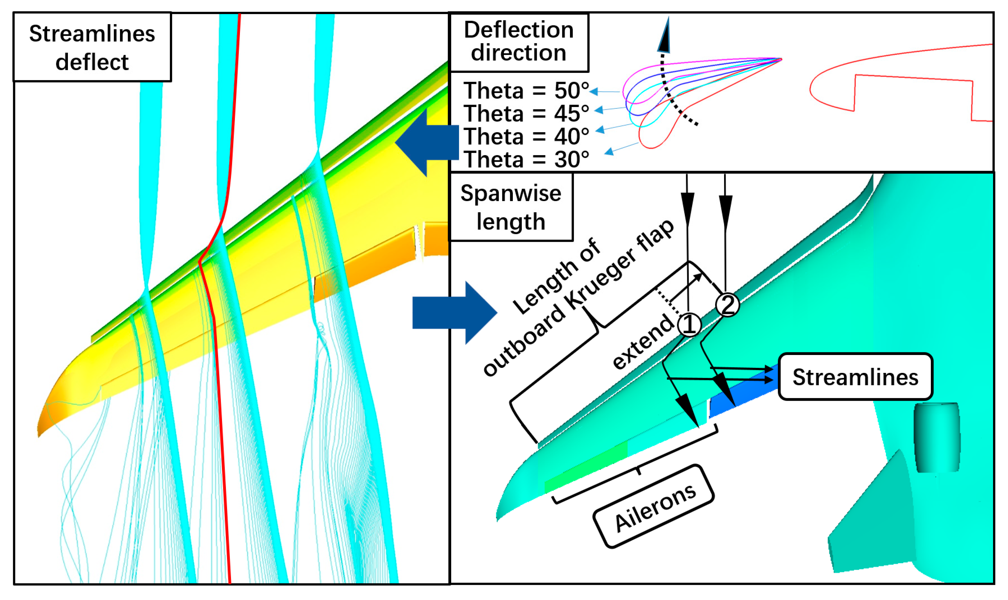
The deflection direction of the Krueger flap is then considered. The purpose of this paper is to improve the stall state of the aileron region in the high lift configuration at large angles of attack. The degree of airflow upwash on the leading edge of the wing will be exacerbated with the local adverse pressure gradient increases if the Krueger flap angle is reduced. If the Krueger flap angle is reduced, the local adverse pressure gradient will increase with the degree of airflow upwash on the leading edge of the wing being exacerbated. Eventually, the stall in the aileron region becomes more serious. Therefore, the configurations of Theta 40°, 45°, and 50° are considered sensitivity analysis configurations. However, the definition of Theta is not enough for sensitivity analysis. The Krueger flap area where Theta changes must be initialized, so the spanwise length of the Krueger flaps redesigned is considered. “Length” is defined as the length of the outboard Krueger flap. The outboard Krueger flap will be redesigned, but it is not linear for the flow control of the Krueger flap to the wing along the flow direction shown in Figure 13. Due to the three-dimensional effect with the wing sweep angle, the spanwise flow in the slot is strong, which causes the streamlines through the slot to be deflected towards the wing tip instead of flowing directly towards the trailing edge of the wing in the direction of the freestream. Therefore, the length should be extended from cycle 1 to cycle 2 to ensure that the flow control measure from the Krueger flap is effective for the entire aileron zone.
The CFD numerical simulation results with Mach number 0.15 and Reynolds number 8.90 × 10⁷ are shown in Figure 14 and 
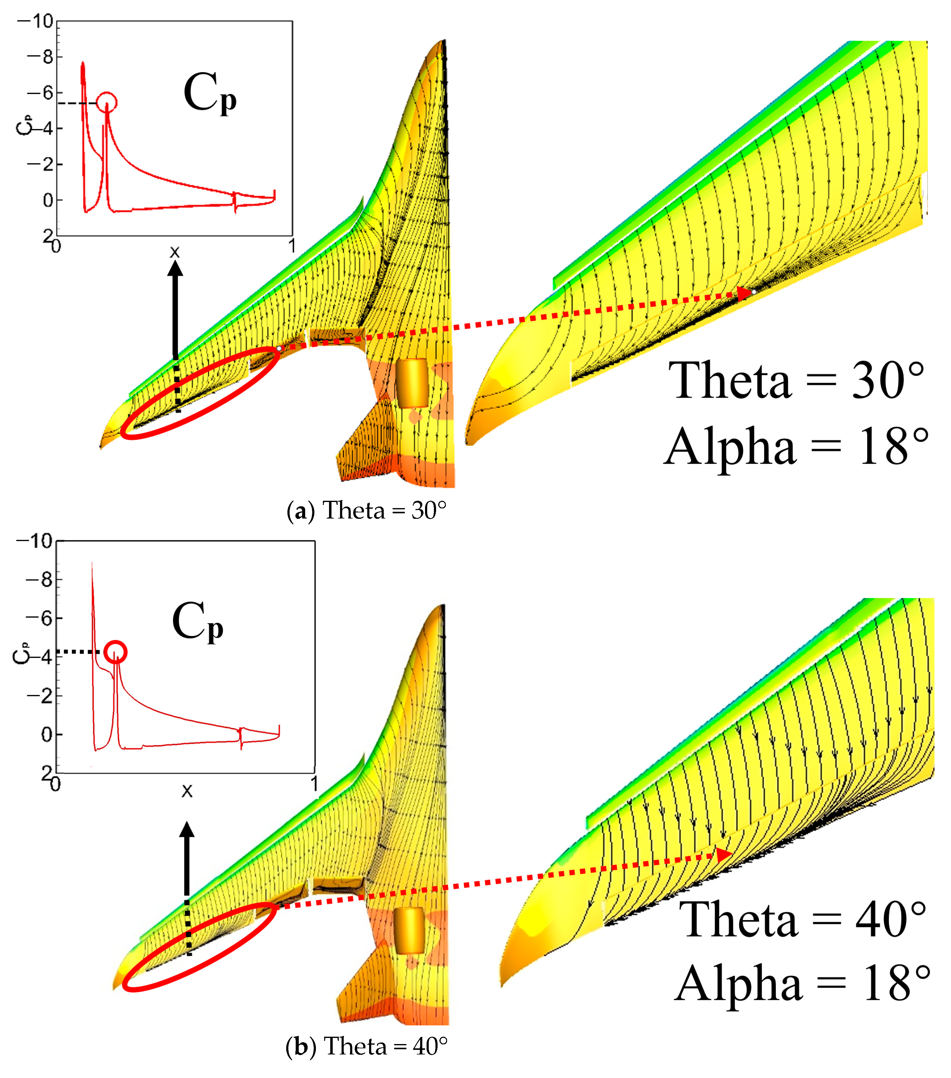
Figure 15. The sensitivity of the BWB high lift configuration studied in this section to the variation in the Krueger flap angle Theta is described from four aspects: stall state, lift characteristics, moment characteristics, and pressure distribution in the aileron zone. When Theta is 40°, there is a slight spanwise flow at the trailing edge of the outboard aileron, which is improved compared to the original high lift configuration, but the spanwise flow in the inboard aileron is still serious with a tendency for separation. When Theta is 45°, the flow in the outboard aileron is already very good, and there is only a slight spanwise flow in the inboard aileron. When the Theta is 50°, there is no obvious spanwise flow between the ailerons, and the improvement is extremely obvious compared with the original high lift configuration. Compared with the original high lift configuration, the adverse pressure gradient of Theta 50° drops more greatly, which greatly inhibits the flow separation in the aileron region, but causes a larger loss of local lift according to the comparison of pressure coefficient difference between Theta 30° and Theta 50°. Therefore, with the increase in the Krueger flap angle Theta from 30° to 50°, the streamline of the aileron shown in Figure 14 is gradually straightened. Additionally, the stall state is gradually improved 18° angle of attack. This is because the negative pressure peak in Cp of Figure 14 gradually decreases, resulting in the weakening of flow separation with a gradual decrease in the local adverse pressure gradient. This is because by increasing Theta at the same Alpha, the direction of the upwash flow induced by the Krueger flap on the leading edge of the wing will be more tangential to the direction of the upper wing surface, which leads to a result of gentler airflow over the leading edge of the wing. The negative pressure peak is reduced with a gentle flow. The increase in the Krueger flap angle Theta is very effective in ensuring the stall state of the aileron only from the point of view of suppressing the stall at the trailing edge. It should also be noted that the stall of the outboard aileron is easier to be improved.
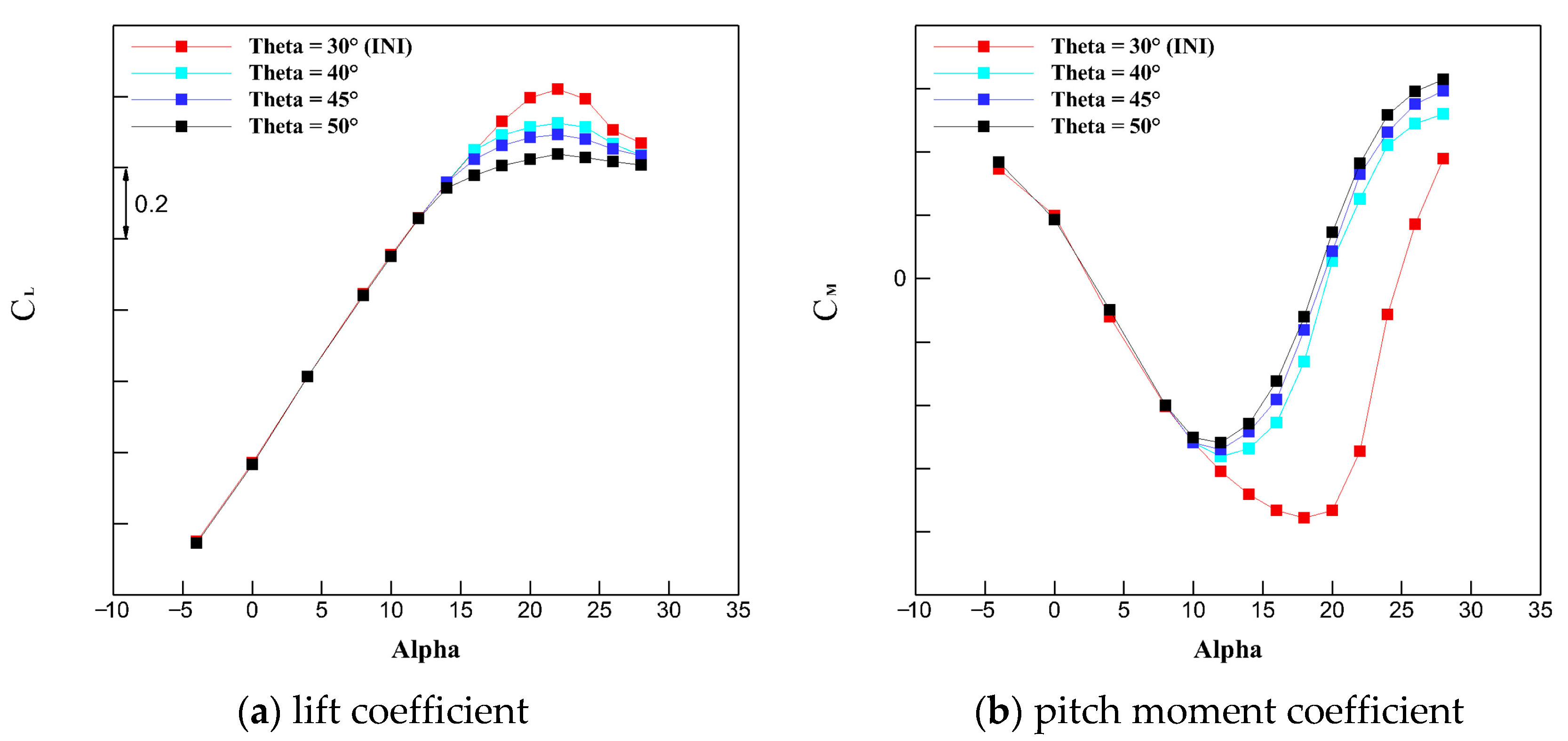
Figure 15a shows the sensitivity results of the lift characteristic. The “INI” in Figure 15 represents the initial high lift configuration. It can be seen that the lift curves in different Theta have very little difference at the angle of attack from −4° to 12°, and they all increase linearly. When the angle of attack is greater than 12°, the lift coefficient curves of the high lift configuration for each Theta are significantly different. The stall angle of attack did not change (22°), and the stalled process slowed down, which corroborates mutually with the aileron streamline state in Figure 14. However, the maximum lift coefficient CLmax dropped by about 0.2 from Theta 30° to Theta 50°, which corroborates mutually with the Cp in Figure 14. In short, with the increase in Theta, the stall characteristics become better, but the lift loss is gradually unacceptable.
Figure 15b shows the sensitivity results of the pitch moment characteristic. At the Alpha from −4° to 10°, the longitudinal static stability characteristics are good since the pitch moment coefficients decrease with the increase in the Alpha at each Theta. From Theta 40° to Theta 50°, when the Alpha is greater than 10°, the pitch moment coefficient curve moves slightly upward as the Theta increases. Therefore, the change in the Theta in the local Krueger flap will slightly change the pitch moment value under the condition of a large angle of attack, while it has little effect on the angle of minimum pitch moment. When Alpha is greater than 10°, the longitudinal static stability of the configurations of sensitivity analysis rapidly deteriorates. The angles of minimum pitch moment are 12°and these are 6° less than the original high lift configuration, which will greatly limit the available angle of attack when the aircraft takes off and lands. The outboard wing is located behind the center of mass of the aircraft and provides mainly nose-down pitch moments. Changing Theta will reduce the lift of the outboard wing, thus causing the nose-down pitch moment value provided by the outboard wing to reduce. However, the nose-up moment value provided by the inboard wing and the airframe in front of the center of mass has not changed. Therefore, the total pitching moment of the aircraft increases. This is why the angle of the minimum pitch moment decreases, and it is further analyzed in the next section with the spanwise lift distribution. The angle of attack of civil aircraft is not allowed to exceed the angles of minimum pitch moment. Therefore, it is also unacceptable for the BWB that the angles of minimum pitch moment of the configurations of sensitivity analysis reduce 4°compared to the initial high lift configuration.
In short, through the above sensitivity analysis, in terms of stall characteristics, locally increasing the Krueger flap angle can reduce the adverse pressure gradient of the wing and effectively improve the stall characteristics of the aileron zone, but in terms of aerodynamic characteristics, which would cause a certain loss of lift characteristics and move the nonlinear segment of the pitching moment upward as a whole.
In addition, the angles of the minimum pitch moment of the sensitive configurations are relatively advanced. It is speculated that the length of the outboard Krueger flap length determines the position of the angles of minimum pitch moment. Therefore, the sensitivity analysis of the length will be investigated in the next section, focusing on the relationship between length and the angle of minimum pitch moment.

4.3.2. Sensitivity Analysis of Length of the Outboard Krueger Flap

This section conducts a sensitivity analysis of the length of the outboard Krueger flap. In the previous section, changing part of the Krueger flap angle resulted in a large change in the longitudinal static stability of the BWB civil aircraft. (The angles of minimum pitch moment are 12°, and these are 6° less than the original high lift configuration.) However, only changing the deflection angle of the Krueger flap did not change the angle of minimum pitch moment from Theta 40° to 50°as shown in Figure 15b. It is worth noting that changing the Theta also inevitably changes the length of the outboard Krueger flap. The length determines the range of effect of the outboard Krueger flap after changing the outboard Krueger flap declination angle, thereby affecting the lift distribution of the entire wing. Therefore, it is speculated that the length of the outboard Krueger flap determines the angles of the minimum pitch moment.
The length of the outboard Krueger flap defined as “Length” in the previous section needs to be parameterized now. As shown in Figure 16, the sensitivity analysis of the length was carried out by taking the lengths 30%, 45%, and 60%.
The CFD numerical simulation results with Mach number 0.15 and Reynolds number 8.90 × 10⁷ are shown in Figure 17 and Figure 18. The sensitivity of the BWB high lift configuration studied in this section to the variation in the length of outboard Krueger flap length is described from three aspects: stall state, lift characteristics, and moment characteristics in the aileron zone. The focus is on the change in moment characteristics.
Figure 17 shows the surface limiting streamlines of the sensitive configurations, which is similar to the situation in the previous section. As the length increases, the zone of perfect streamline gradually expands from the outboard aileron to the inboard aileron, and the stall state gradually becomes better. The adverse pressure gradient of Cp drops obviously. However, unlike in the previous section, the surface limiting streamlines of the outboard aileron zone are always perfect in this section about the sensitive analysis of the length. When the length is 30%, the flow of the outboard aileron zone is perfect, but the separation of the inboard aileron zone is serious. When the length is 60%, there is no obvious strong spanwise flow on the inboard and outboard ailerons, and the surface flow is very good. Thus, the spanwise length of the stall zone is controlled by the length.
Figure 18a shows the sensitivity results of the lift characteristic. It can be seen that as the length increases gradually, the effect of the high-lift device gradually becomes worse, which is also similar to the situation in the previous section. Therefore, the length is negatively correlated with the high lift effect. The local stall state at the high angle of attack in the aileron zone of each sensitive configuration has been improved, and the overall stall process has become moderate.
Figure 18b is the result of the pitch moment of sensitivity about length. It can be seen from Figure 18 that as the Alpha changes from −4° to 10°, the pitch moment coefficients of different lengths have the same trend as the Alpha. When the angle of attack is smaller than the minimum pitch moment angle, the static margin is mainly maintained at around 6.8%. (Aircraft of blended wing body layout have a weaker capacity for longitudinal flattening than conventional layout plane due to the shorter body. Therefore, its static margin is smaller than in a general layout plane.) Thus, the longitudinal static stability characteristics are good. However, when the Alpha is greater than 10°, the angle of the minimum pitch moment of each sensitive configuration decreases with the increase in length. The calculation results are consistent with the speculation in the previous section. As the length increases from 0% to 60%, the angle of minimum pitch moment decreases from 18° to 12°, so the length of the outboard Krueger flap has a great influence on the longitudinal static stability of the BWB. The larger the angle of the minimum pitch moment, the greater the angle of attack available to the aircraft for safe flight. The pitch moment characteristic caused by the length is further analyzed with the spanwise lift distribution.
Figure 19 is the spanwise lift distribution of Theta sensitivity in Section 4.3.1 and length sensitivity in Section 4.3.2. The x coordinate is dimensionless, “b” represents the spanwise length of the aircraft, “CL_Local” represents the local lift coefficient and “C” represents the local chord. As can be seen from Figure 19, all the curves can be divided into two parts. The part of the outboard wing where the ailerons are located has less local lift than that of the inboard wing. In the part of the inboard wing where the flaps are located, the local lift is large because the flaps are in working condition. That is why the local lift has a large jump at the junction of the aileron zone and the flap zone. The outboard wing is highlighted by the dashed line, as this is the main study area. The black line represents the final configuration. It should be noted that Theta = 50°and length = 60% are the same configuration. According to the criterion of the control variable method, the spanwise lift distribution of the initial configuration (INI: Theta = 30°, length = 0%) is hidden. The “CL” and “CM” in Figure 19 represent lift and pitch moment characteristics. It can be seen that the sensitivity analysis of Theta and length have almost similar CL change (the difference between the maximum lift coefficients of any two adjacent sensitive configurations, such as the configurations Theta = 40°and Theta = 45° or the length of the configuration = 30% and length = 45%, is about 0.05) with the respective increase in Theta and length, but the CM change is distinct. This is because the change in the CL is mainly related to the lift loss, while the change in CM is not only related to the change in lift loss but also the difference in the pressure center location. The pressure center location is determined by the spanwise lift distribution. It can be seen from the spanwise lift distribution in Figure 19 and Figure 20 that when Theta increases, the lift loss is almost uniformly distributed over the entire outboard wing. However, when the length increases, the lift loss is concentrated in a specific zone where the length changes. Therefore, the results of the pressure center location indicate that the diverse ways of changing the spanwise lift distribution are the reason why there is an extreme variation in CM between the length and Theta.
In short, changing the length changes the confrontation between the nose-up moment and the nose-down moment in Figure 20. The angle of attack corresponding to the CLmax of the local lift and the angle of minimum pitch moment is also changed. Increasing the length makes the pressure center location change greatly. That is the reason why the pitching moment coefficient CM is very sensitive to length.

4.3.3. The Design of Aileron Surface Flow State

According to the sensitivity analysis before, it can be found that the stall characteristic of the aileron zone is sensitive to Theta and length. The increase in Theta suppresses the stall in the aileron zone. Additionally, the increase in the length reduces the spanwise length of the flow separation in the aileron zone. However, the increase in Theta degrades the lift characteristic seriously, while the increase in the length makes the lift characteristic and pitching moment characteristic significantly worse. Therefore, it is necessary to carry out a subtle design of the Theta value and length value of the Krueger flap, which not only effectively improves the stall characteristics of the aileron region but also makes the cost of lift characteristic and pitching moment characteristic acceptable. If the stall state of the entire aileron zone is guaranteed to be good, the cost of lift characteristic and pitching moment characteristic will be very high, such as the configuration with Theta 50°and length 60% of outboard Krueger flap. Considering the constraints such as aileron flow state, lift characteristic, pitching moment characteristic, achievability of Krueger flap motion mechanism, and wing structure, the following design parameters are finally obtained: Theta = 41.5° and length = 35%. The configuration with the parameters Theta = 41.5° and length = 35% of the outboard Krueger flap is defined as Design Configuration 1.
The CFD numerical simulation results with Mach number 0.15 and Reynolds number 8.90 × 10⁷ are shown in Figure 21 and Figure 22. The design configuration 1 studied in this section is described from three aspects: stall state, lift characteristic, and moment characteristic in the aileron zone.
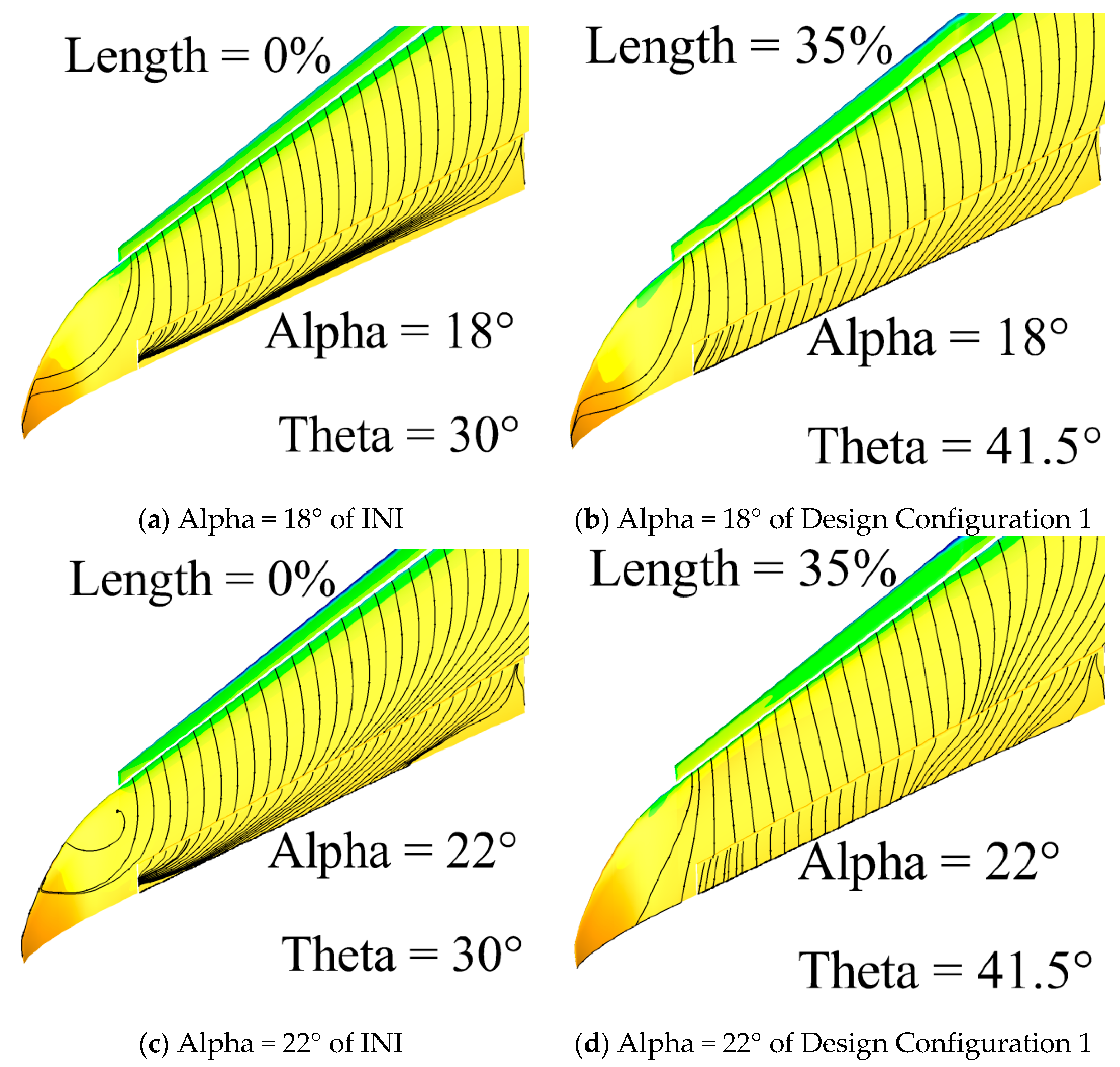
At Alpha = 18° and Alpha = 22°, relatively strong spanwise flow is generated in the entire aileron zone of INI, shown in Figure 21a,c. However, the surface limiting streamline of the outboard aileron zone of Design Configuration 1 shown in Figure 21b,d is relatively straight, implying that there is no strong spanwise flow, and the stall state is good. The limiting streamline on the surface of the inboard aileron has a slight spanwise flow trend, and the stall characteristic of the aileron zone in Design Configuration 1 compared with the INI has been significantly improved.
At Alpha changes from −4° to 16°, the difference in the lift curves shown in Figure 22a between INI and Design Configuration 1 is very small. When the Alpha is greater than 16°, the lift coefficient curves have a little difference between INI and Design Configuration 1. The CLmax is reduced by 0.06, and the stall process slows down with the stall angle of attack maintained as 22°for Design Configuration 1. From Alpha −4°to Alpha 16°shown in Figure 22b, the change trends of the pitch moment coefficient with the angle of attack between INI and Design Configuration 1 are consistent, and the static stability characteristics are good. When the Alpha is greater than 16°, the pitching moment of Design Configuration 1 gradually increases, and the angle of the minimum pitching moment is 16°, which is 2° smaller than the INI. Therefore, Design Configuration 1 pays a high cost of the pitching moment characteristic to eliminate the spanwise flow in the aileron zone.
In summary, Design Configuration 1 can effectively improve the spanwise flow in the aileron zone, and the lift characteristics are acceptable, but the cost of the pitch moment characteristics is high, which requires a further fine design to increase the angle of minimum pitch moment for the longitudinal static stability.
Based on the above design results and the previous sensitivity analysis results, it is found that there is a contradiction between aerodynamic coefficients and stall characteristics. At the large angle of attack, the better the stall characteristic of the BWB aileron zone, the worse the lift coefficient and pitch moment coefficient are under the condition that the airfoil of this aircraft can not be changed. The contradictions need to be reconciled to solve the stall problem in the aileron zone at the expense of acceptable aerodynamic characteristics at the appropriate location. However, the above analysis shows that Design Configuration 1 obtained only by designing the parameters Theta and length cannot perfectly reconcile this contradiction (the angle of minimum pitching moment is reduced by 2°). Therefore, it is vital to find a new solution to this problem.
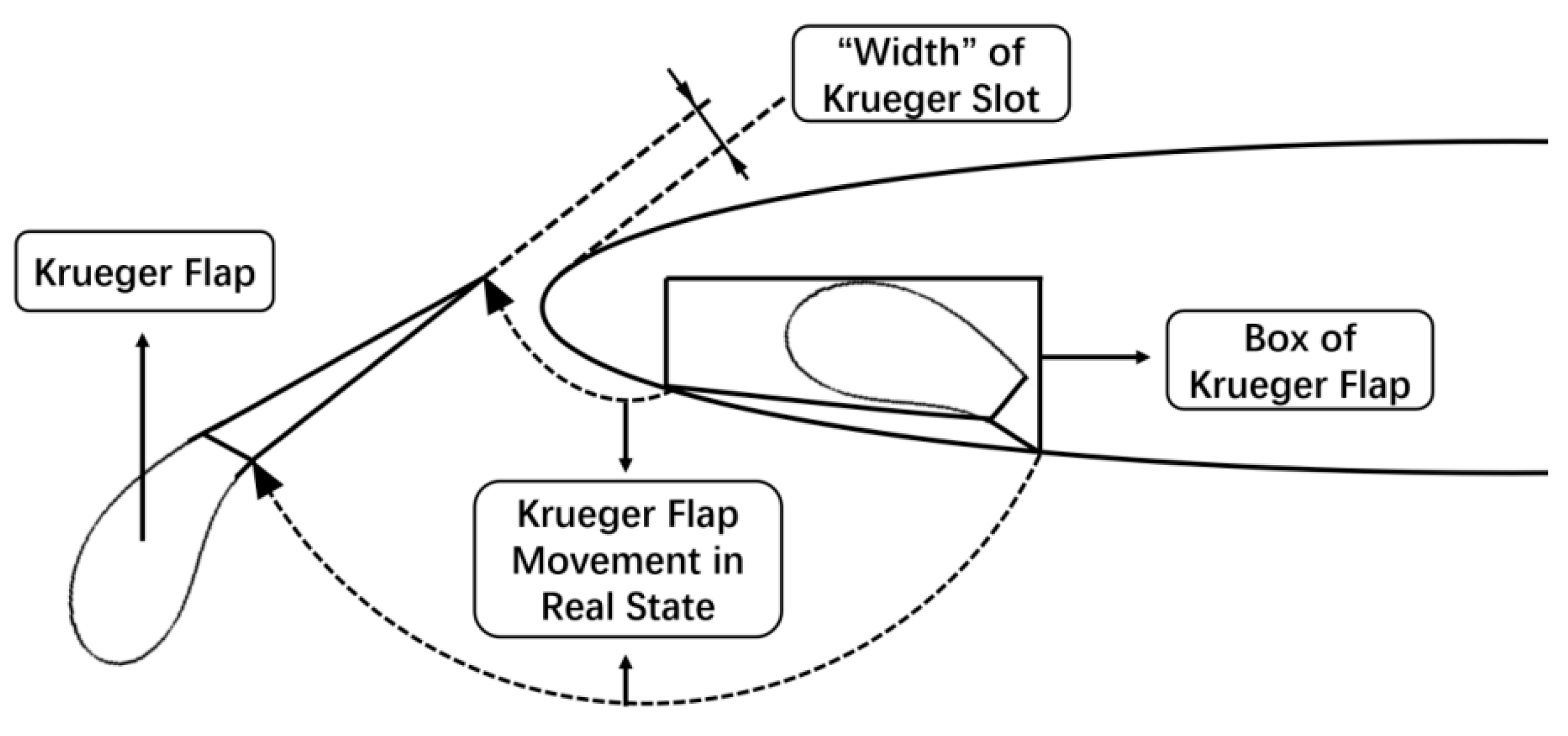
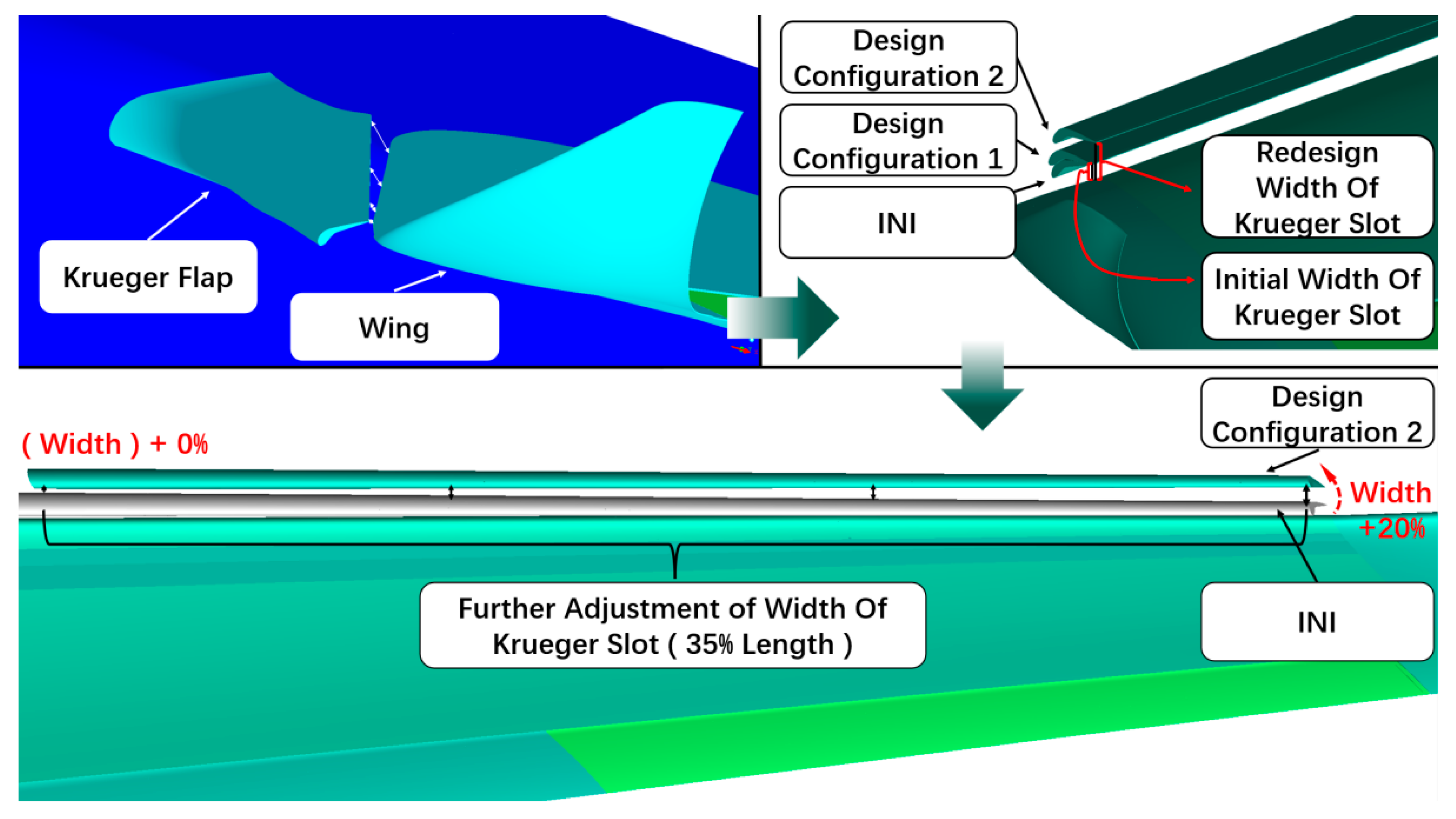
It is worth noting that the stall problem in the outboard aileron zone is easier to be improved than in the inboard aileron zone. When the stall state of the inboard aileron zone is relatively great, in fact, the outboard aileron zone has been improved too much. Therefore, there is redundancy in the stall improvement in the outboard aileron zone. The longitudinal static stability loss caused by Design Configuration 1 (the angle of minimum pitching moment reduced by 2°) can be corrected by appropriately reducing the flow control to the outboard wing. That has no effect on the improvement of the stall characteristic of the outboard aileron zone by Design Configuration 1. As shown in Figure 23, it is found that the slot between the Krueger flap and the wing at the wing tip is narrower (zone of the white arrow) than the slot near the blend wing body. Flow over the upper surface of the wing is induced by the lower surface of the Krueger flap, forming an upwash flow through the slot. It is a great method to solve the stall problem by studying flow control [28,29,30]. Through the CFD analysis of the slot width, within a certain range, the narrower the slot, the stronger the flow control effect of the Krueger flap. Therefore, a refined design of the width of the Krueger flap slot is considered. Width is defined as the width of the Krueger flap slot. Through the iterative design of the width, the final Krueger flap was operated as follows under the condition that the Krueger flap kinematic mechanism is guaranteed to be achievable. On the one hand, based on Design Configuration 1, the width is doubled to slightly reduce the flow control of the outboard wing. On the other hand, based on the previous step, the spanwise distribution of the width is further finely adjusted. Based on the investigable results of the arm of force in Figure 19 and Figure 20 and the relationship between stall state and aerodynamic characteristics, the width is further increased by 20% of its width. Finally, Design Configuration 2, shown in Figure 23, is obtained by slightly weakening the stall characteristic of the aileron zone in the above design and compensating for the loss of aerodynamic characteristics of Design Configuration 1.
The CFD numerical simulation results with Mach number 0.15 and Reynolds number 8.90 × 10⁷ are shown in Figure 24 and Figure 25. Design Configuration 2 investigated in this section is described from three aspects: stall state, lift characteristic, and pitch moment characteristic in the aileron zone.
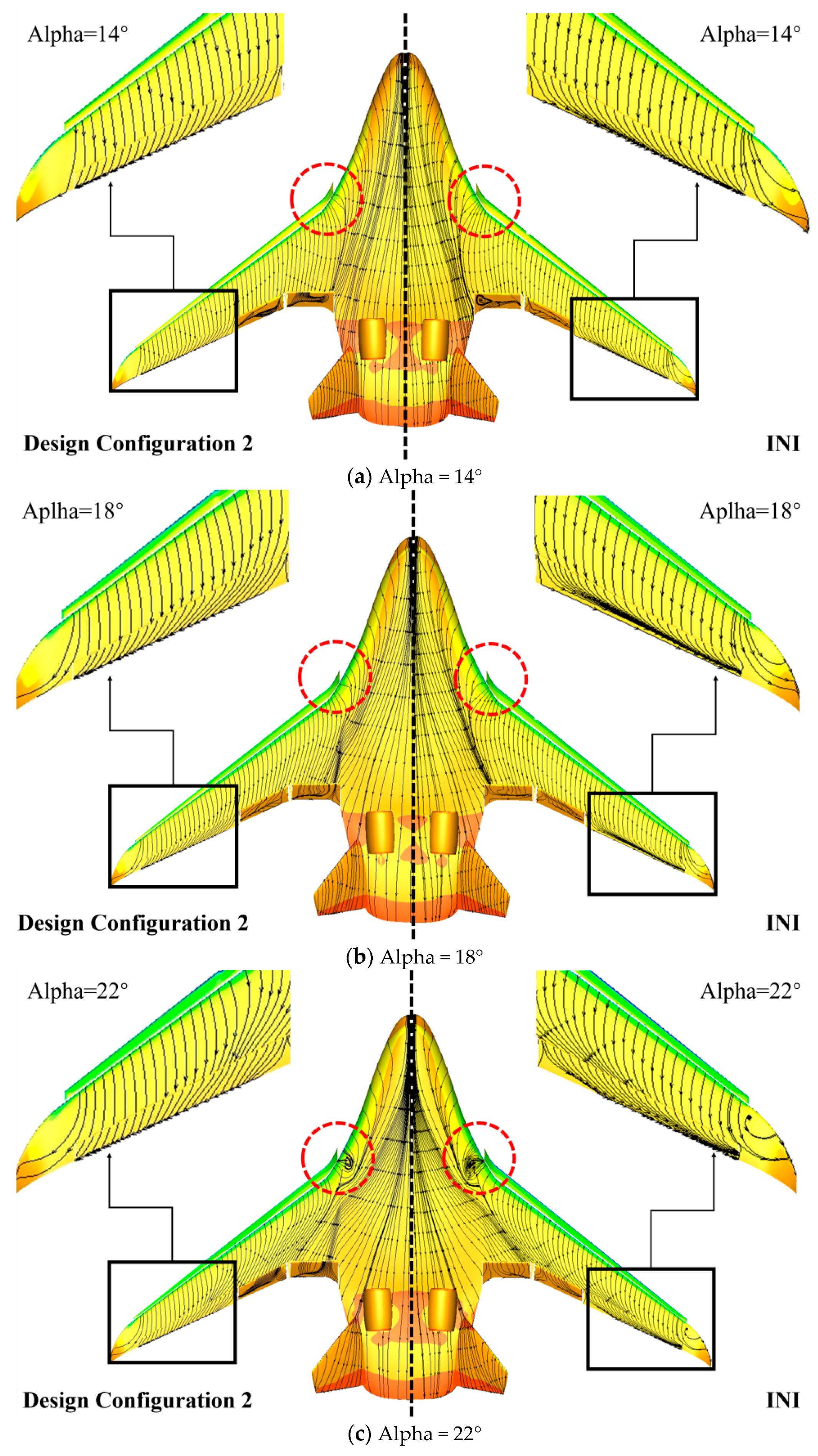
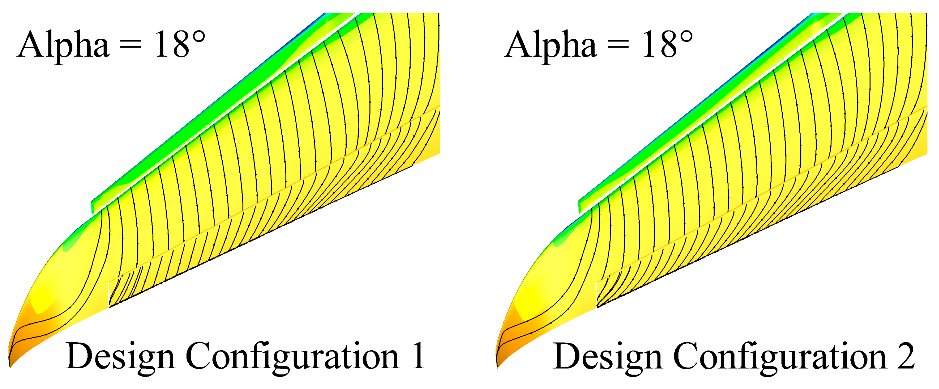
The separation flow in the aileron zone of INI shown in Figure 24 is strong at Alpha 18° and Alpha 22°, so their local stall characteristics are bad. Although there is a slight spanwise flow trend on the surface limiting streamline of the aileron zone of Design Configuration 2, the overall streamline is relatively straight, and the stall characteristic is good all the time. Therefore, increasing the width has no obvious bad effect on the flow control of the Krueger flap to the wing. In addition, the flow separation, red circle line in Figure 24, occurs first at the blend wing body at the Alpha 22° when the surface flow on the upper aileron is good so that the aircraft can obtain an obvious stall signal (lift drop) before the aileron is in hidden danger of control in the Design Configuration 2 at a high angle of attack.
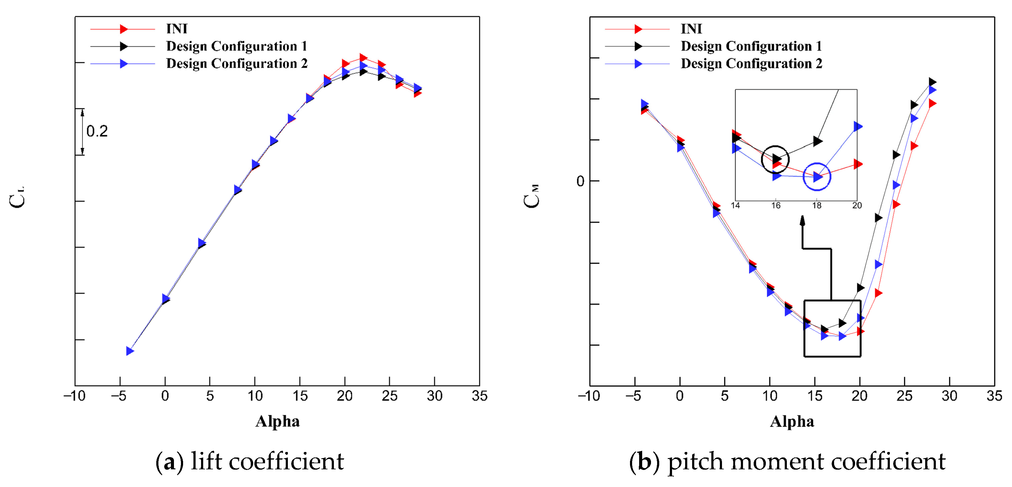
At Alpha from −4°to 16°, the difference of the lift curves shown in Figure 25a between INI and Design Configuration 2 is very small, and they all increase linearly. When the Alpha is greater than 16°, the lift coefficient curves have a little difference between INI and Design Configuration 2. The CLmax is reduced by 0.03 for INI and increased by 0.03 for Design Configuration 1. The stall angle of attack did not change, it was 22°, and the stall process slowed down. The outboard Krueger flaps are less costly to suppress flow separation in the aileron zone.
From the Alpha −4°to 16°shown in Figure 25b, the change trends of the pitch moment coefficient with the angle of attack between the INI and the Design Configuration 2 are consistent, and the static stability characteristics are good. When the Alpha is greater than 16°, the pitching moment of Design Configuration 1 gradually increases, and the angle of the minimum pitching moment is 16°. However, the pitching moment of Design Configuration 2 continues to decrease and maintain the great static stability characteristic. When the Alpha is greater than 18°, the pitching moment of both the INI and the Design Configuration 2 starts to increase, so the angle of minimum pitch moment of the Design Configuration 2 is 18°, which is the same as the INI and better than the Design Configuration 1. At the same time, the aileron streamlines of Design Configuration 2 shown in Figure 26 after widening the Krueger slot are slightly more deflected in the spanwise direction than that of Design Configuration 1, which is the price of the compromise of the stall characteristic to the aerodynamic characteristics. The pitch moment increase in Design Configuration 2 is slightly faster than that of the INI when the Alpha is greater than 18°, but the overall longitudinal static stability characteristic is basically the same as INI. In short, the design result of increasing the width is as expected.
In summary, appropriately increasing the width achieves better compromise design results from Design Configuration 1 to Design Configuration 2. The Design Configuration 2 can also effectively improve the flow separation in the aileron, with good lift characteristic, good pitching moment characteristic, and the angle of minimum pitch moment that is the same as the INI is 18°. Design Configuration 2, based on better inheriting the great aerodynamic characteristics of the INI, paid a very small price for the lift and pitching moment and completed the improvement of the stall characteristics of the aileron zone. It should be noted that the shape parameters of the Krueger flap can also slightly affect the aerodynamic characteristics, but redesigning the shape of the Krueger flap needs to consider the constraints of the wing structure, which is much more expensive than redesigning the width.
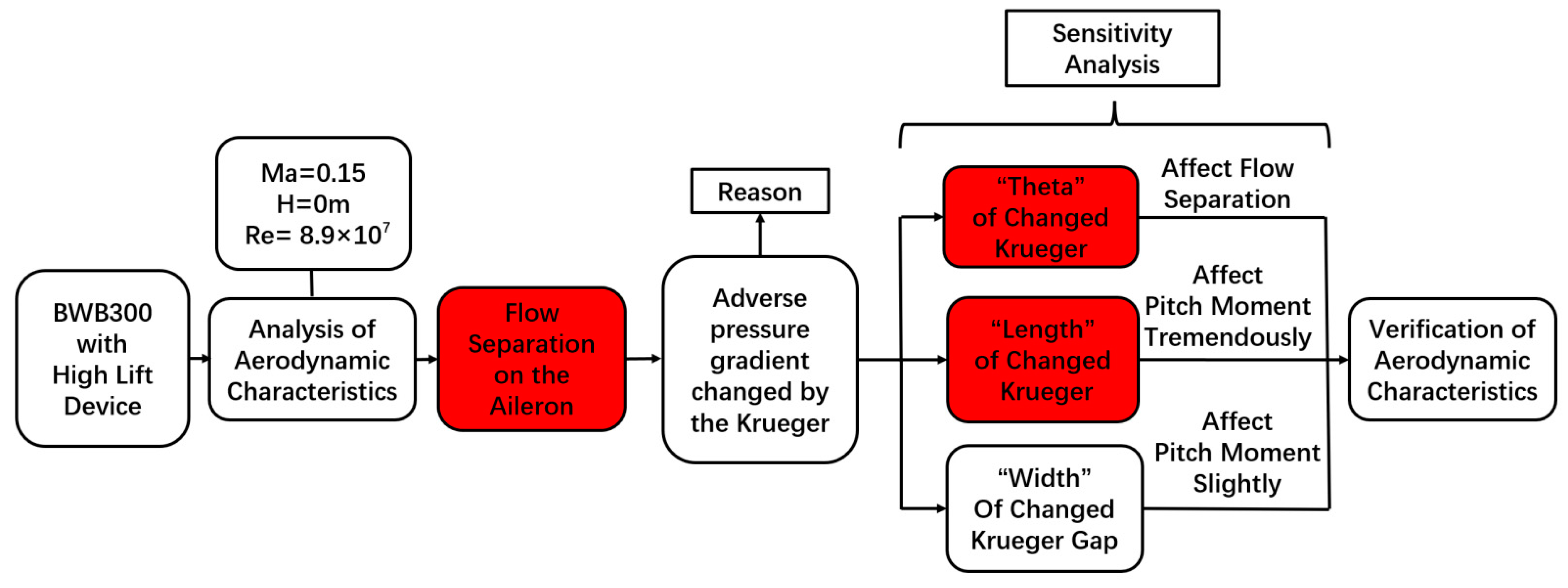
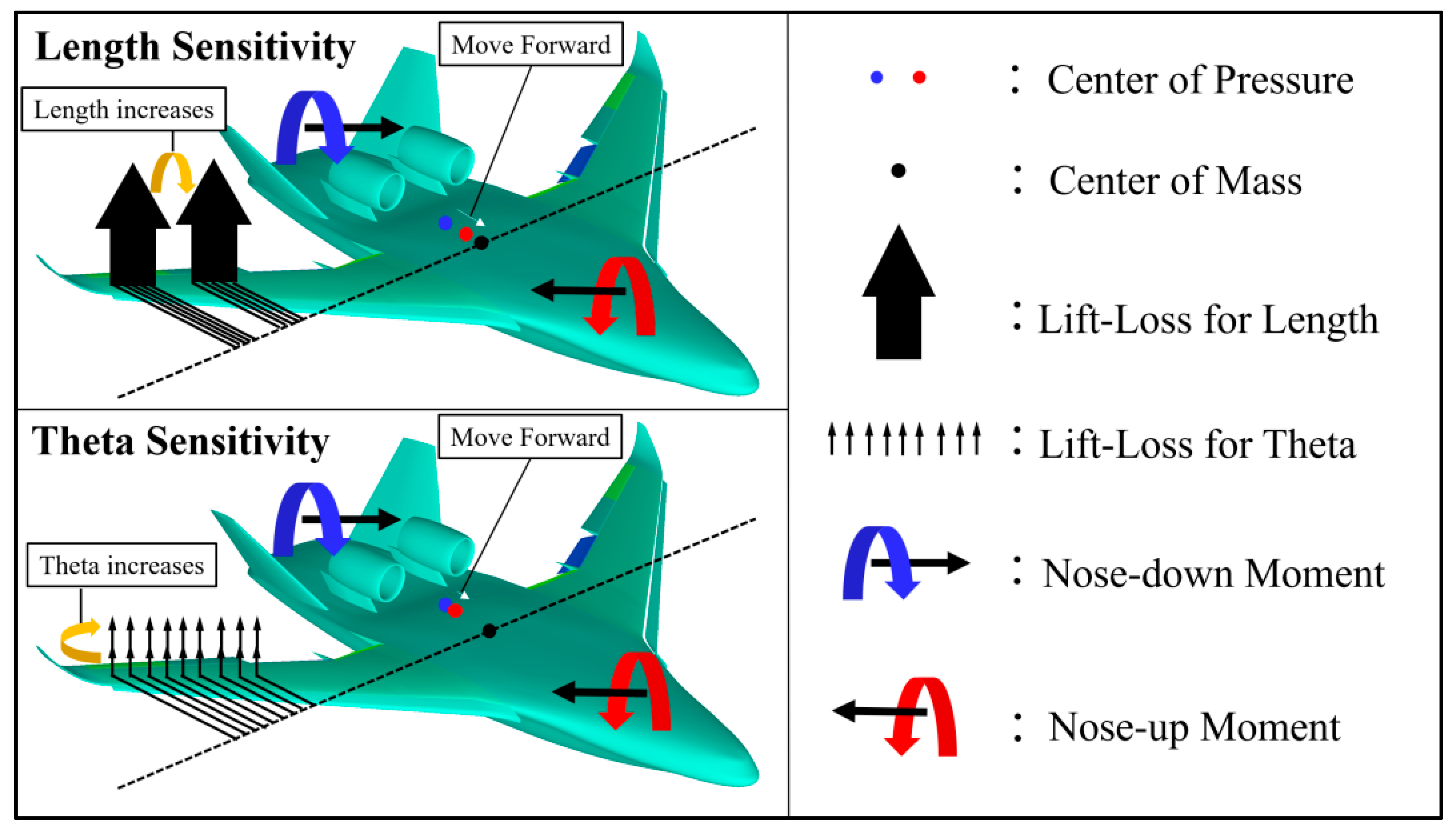
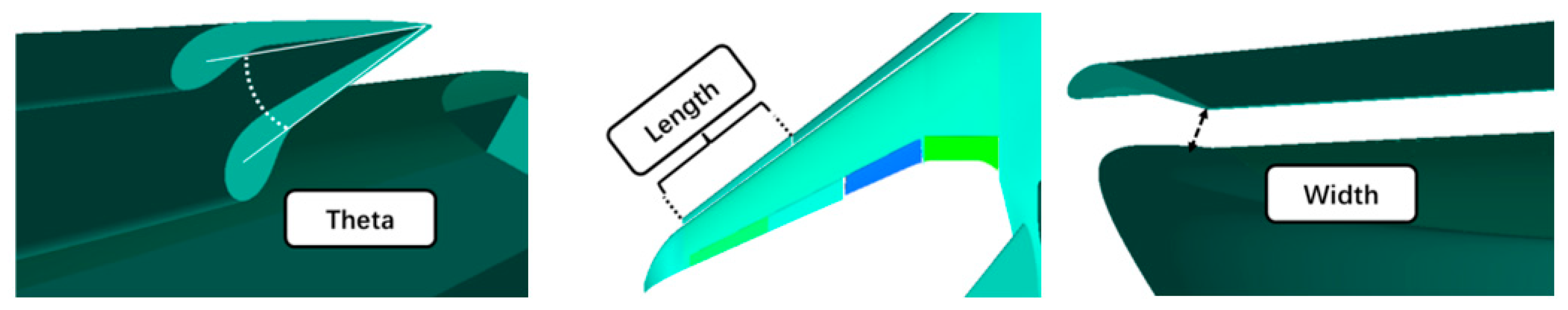
Finally, for the design of the aileron surface flow state characteristics of the three-dimensional Krueger flap, three important adjustment parameters are summarized as shown in Figure 27, which can provide a reference for aerodynamic design work:
(a)
Theta, the angle of the outboard Krueger flap, affects flow separation mainly;
(b)
Length, the length of the outboard Krueger flap, affects pitch moment tremendously;
(c)
Width, the width of the outboard Krueger flap slot, affects pitch moment slightly.

5. Conclusions

A detailed study of the improved design on the aileron surface flow state of high lift configuration in BWB using steady CFD simulations and wind tunnel tests were presented in this paper. The predicted trends of the aerodynamic coefficients and the stall characteristic of the aircraft were consistent with the wind tunnel data. Finally, several conclusions can be determined as follows:
(1) The angle of the outboard Krueger flap has a significant effect on the stall characteristic and high lift characteristic in the aileron zone at a high angle of attack. The larger angle of the Krueger flap (the angle ranges from 30° to 50°), the better the stall characteristic in the aileron zone. However, at the same time, it will pay a higher price for the lift loss and the longitudinal static stability.
(2) The length of the outboard Krueger flap has a significant effect on the longitudinal static stability at a high angle of attack. The longer the length of the outboard Krueger flap (the length ranges from 0% to 60%), the greater the angle of the minimum pitching moment and the lift loss. However, the longer the length, the longer the spanwise improvement distance of the aileron stall zone.
(3) The width of the outboard Krueger flap slot has slight effects on aerodynamic characteristics and stall characteristics, and the effect on pitch moment characteristic is slightly larger than the stall and lift characteristics at a high angle of attack. The larger the width, the weaker the flow control of the Krueger flaps on the wing and the better the aerodynamic characteristics. On the premise that the Krueger flap motion mechanism can be realized, it makes up for the defects of the inability of the subtle adjustment between the aerodynamic characteristics and stall characteristics for two parameters, Theta and length.
(4) The Krueger flap design criterion for BWB aileron surface flow state is proposed. The Krueger flaps should be divided into two sections, inboard, and outboard Krueger flap. These two sections are both responsible for improving lift, but the outboard Krueger flap should also ensure that the good stall characteristic is on the aileron throughout the extreme angle of attack. When designing the outboard Krueger flap, the angle of the outboard Krueger flap is designed firstly to ensure the stall characteristics in the aileron zone. Then the length of the outboard Krueger flap is designed to generally ensure the good lift characteristic and pitch moment characteristic. Finally, a subtle redesign of the width of the Krueger flap slot is carried out to complete the coordination of stall characteristics and aerodynamic characteristics.
In the present study, the investigation was made at a typical angle of attack under the take-off conditions. In the future, the effects of the high-lift device redesign will be analyzed and discussed from more angles of attack to validate the applicability of the conclusions presented in this paper by using hybrid RANS/LES methods and wing tunnel tests to improve the accuracy of the numerical results.

Author Contributions

Writing—original draft preparation, X.N.; writing—review and editing, Z.Y.; supervision, H.Z.; funding acquisition, J.L. All authors have read and agreed to the published version of the manuscript.

Funding

This research was funded by the National Natural Science Foundation of China (NSFC) under Grant Number 11972304.

Conflicts of Interest

The authors declare no conflict of interest.

References

  1. Roskam, J. Airplane Design; DARcorporation: St. Lawrence, KS, USA, 1985. [Google Scholar]
  2. Stinton, D. The design of the airplane; American Institute of Aeronautics and Astronautics, Inc.: Reston, VA, USA, 2001. [Google Scholar]
  3. Zhang, M.; Chen, Z.; Mao, J.; Wang, G.; Tan, Z.; Wang, L. Design of krueger flap for civil aircraft with blended-wing-body. Acta Aeronaut. Et Astronaut. Sinica. 2019, 40, 623048. [Google Scholar]
  4. Smith, A.M.O. High-lift aerodynamics. J. Aircr. 1975, 12, 501–530. [Google Scholar] [CrossRef] [Green Version]
  5. Panagiotou, P.; Mitridis, D.; Dimopoulos, T. Aerodynamic design of a tactical Blended-Wing-Body UAV for the aerial delivery of cargo and lifesaving supplies. In Proceedings of the AIAA Scitech 2020 Forum, Orlando, FL, USA, 6–10 January 2020; p. 1958. [Google Scholar]
  6. Dehpanah, P.; Nejat, A. The aerodynamic design evaluation of a blended-wing-body configuration. Aerosp. Sci. Technol. 2015, 43, 96–110. [Google Scholar] [CrossRef]
  7. Wildschek, A. Flight dynamics and control related challenges for design of a commercial blended wing body aircraft. In Proceedings of the AIAA Guidance, Navigation, and Control Conference, National Harbor, MD, USA, 13–17 January 2014; p. 0599. [Google Scholar]
  8. Okonkwo, P.; Smith, H. Review of evolving trends in blended wing body aircraft design. Prog. Aerosp. Sci. 2016, 82, 1–23. [Google Scholar] [CrossRef]
  9. Thiede, P. EUROLIFT-advanced high lift aerodynamics for transport aircraft. Air Space Europe 2001, 3, 105–108. [Google Scholar] [CrossRef]
  10. Van Dam, C.P. The aerodynamic design of multi-element high-lift systems for transport airplanes. Prog. Aerosp. Sci. 2002, 38, 101–144. [Google Scholar] [CrossRef] [Green Version]
  11. Yu, G.; Li, D.; Zhang, Z. Numerical simulation for the differences between FTN/WPN engine models aerodynamic influence on BWB300 airframe. Eng. Appl. Comput. Fluid Mech. 2020, 14, 566–579. [Google Scholar] [CrossRef] [Green Version]
  12. Yang, Z.; Li, J. Numerical Aeroelastic Analysis of a High-Aspect-Ratio Wing Considering Skin Flexibility. Aerospace 2022, 9, 515. [Google Scholar] [CrossRef]
  13. Niu, X.; Li, J. Investigation and Design of the Transonic Laminar Flow Characteristics in a Laminar Aircraft. Appl. Sci. 2022, 12, 11820. [Google Scholar] [CrossRef]
  14. Thompson, T. Technology Portfolio Analysis for Environmentally Responsible Aviation. In Proceedings of the AIAA/3AF Aircraft Noise and Emissions Reduction Symposium, Atlanta, GA, USA, 16–20 June 2014; p. 2875. [Google Scholar]
  15. Bradley, M.K.; Droney, C.K.; Allen, T.J. Subsonic Ultra Green Aircraft Research; NASA Center for AeroSpace Information: Greenbel, MD, USA, 2015. [Google Scholar]
  16. Tamigniaux, T.; Stark, S.; Brune, G. An experimental investigation of the insect shielding effectiveness of a Krueger flap/wing airfoil configuration. In Proceedings of the 5th Applied Aerodynamics Conference, Monterey, CA, USA, 17–19 August 1987; p. 2615. [Google Scholar]
  17. Wicke, K.; Linke, F.; Gollnick, V. Insect contamination impact on operational and economic effectiveness of natural-laminar-flow aircraft. J. Aircr. 2016, 53, 158–167. [Google Scholar] [CrossRef]
  18. Krueger, W. Systematic Wind-Tunnel Measurements on a Laminar Wing with Nose Flap; UNT Digital Library: Denton, TX, USA, 1947. [Google Scholar]
  19. Niu, C. Airframe Structural Design: Practical Design Information and Data on Aircraft Structures; Conmilit Press Limited: Hong Kong, China, 1999. [Google Scholar]
  20. Akaydin, H.D.; Housman, J.A.; Kiris, C.C. Computational design of a Krueger flap targeting conventional slat aerodynamics. In Proceedings of the 22nd AIAA/CEAS Aeroacoustics Conference, Lyon, France, 30 May–1 June 2016; p. 2958. [Google Scholar]
  21. Bahr, C.J.; Hutcheson, F.V.; Thomas, R.H. A comparison of the noise characteristics of a conventional slat and Krueger flap. In Proceedings of the 22nd AIAA/CEAS Aeroacoustics Conference, Lyon, France, 30 May–1 June 2016; p. 2961. [Google Scholar]
  22. Vicroy, D.D.; Dickey, E.D.; Princen, N. Overview of low-speed aerodynamic tests on a 5.75% scale blended-wing-body twin jet configuration. In Proceedings of the 54th AIAA Aerospace Sciences Meeting, San Diego, CA, USA, 4–8 January 2016; p. 0009. [Google Scholar]
  23. Tang, S.; Li, J.; Wei, Z. A Numerical Investigation of the Dominant Characteristics of A Transonic Flow Over A Hemispherical Turret. Int. J. Comput. Fluid Dyn. 2022, 36, 404–423. [Google Scholar] [CrossRef]
  24. Wei, Z.; Li, J.; Tang, S.; Yang, Z. Investigation and Improvement of T-Tail Junction Flow Separation for a Demonstration Aircraft. Aerospace 2022, 9, 567. [Google Scholar] [CrossRef]
  25. Ikohagi, T.; Shin, B.R.; Daiguji, H. Application of an implicit time-marching scheme to a three-dimensional incompressible flow problem in curvilinear coordinate systems. Comput. Fluids 1992, 21, 163–175. [Google Scholar] [CrossRef]
  26. Choptuik, M.; Unruh, W.G. An introduction to the multi-grid method for numerical relativists. Gen. Relativ. Gravit. 1986, 18, 813–843. [Google Scholar] [CrossRef]
  27. Anderson, J. EBOOK: Fundamentals of Aerodynamics (SI Units); McGraw Hill: New York, NY, USA, 2011. [Google Scholar]
  28. Ni, Z.; Dhanak, M.; Su, T. Improved performance of a slotted blade using a novel slot design. J. Wind. Eng. Ind. Aerodyn. 2019, 189, 34–44. [Google Scholar] [CrossRef]
  29. Yang, Z.; Li, J.; Jin, J.; Zhang, H.; Jiang, Y. Investigation and Improvement of Stall Characteristic of High-Lift Configuration without Slats. Int. J. Aerosp. Eng. 2019, 2019, 7859482. [Google Scholar] [CrossRef]
  30. Wang, G.; Zhang, B. Numerical study on technical and conceptual improvements to a civil aircraft trailing-edge flap using passive/active flow control. Eng. Appl. Comput. Fluid Mech. 2021, 15, 1362–1391. [Google Scholar] [CrossRef]
Figure 1. Definition of the configurations of BWB.
Aerospace 09 00842 g001
Figure 2. Krueger flap movement in real state.
Aerospace 09 00842 g002
Figure 3. Surface grid of the configurations.
Aerospace 09 00842 g003
Figure 4. Aerodynamic forces coefficients of the grid convergence.
Aerospace 09 00842 g004
Figure 5. The experimental models of the BWB.
Aerospace 09 00842 g005
Figure 6. Aerodynamic coefficient results of computation and experiment for the clean configuration and the high lift configuration.
Aerospace 09 00842 g006
Figure 7. The surface flow of computation and experiment for the clean configuration.
Aerospace 09 00842 g007
Figure 8. The entire investigation process of this paper.
Aerospace 09 00842 g008
Figure 9. Aerodynamic coefficient of the high lift configuration in real condition.
Aerospace 09 00842 g009
Figure 10. Upper surface limiting streamlines, the local pressure distribution of the high lift configuration.
Aerospace 09 00842 g010
Figure 11. Upper surface limiting streamlines of the clean configuration.
Aerospace 09 00842 g011
Figure 12. Plan of segmented design of Krueger flap.
Aerospace 09 00842 g012
Figure 13. Sensitivity analysis parameter definition and initialization.
Aerospace 09 00842 g013
Figure 14. Upper surface limiting streamlines, the local pressure distribution of the sensitivity analysis of Theta.
Aerospace 09 00842 g014aAerospace 09 00842 g014b
Figure 15. Aerodynamic coefficient of the sensitivity analysis of Theta.
Aerospace 09 00842 g015
Figure 16. Parameterization of the length of the outboard Krueger flap for sensitivity analysis.
Aerospace 09 00842 g016
Figure 17. Upper surface limiting streamlines; the local pressure distribution of the sensitivity analysis of length.
Aerospace 09 00842 g017
Figure 18. Aerodynamic coefficient of the sensitivity analysis of Length.
Aerospace 09 00842 g018
Figure 19. Spanwise lift distribution of the sensitivity analysis.
Aerospace 09 00842 g019
Figure 20. Arms of force of lift-loss in the sensitivity analysis.
Aerospace 09 00842 g020
Figure 21. Upper surface limiting streamlines of INI and Design Configuration 1.
Aerospace 09 00842 g021
Figure 22. Aerodynamic coefficients of INI and Design Configuration 1.
Aerospace 09 00842 g022
Figure 23. Redesign of the width of the outboard Krueger flap slot.
Aerospace 09 00842 g023
Figure 24. Surface limiting streamlines of INI and Design Configuration 2.
Aerospace 09 00842 g024
Figure 25. Aerodynamic coefficients of INI, Design Configuration 1 and Design Configuration 2.
Aerospace 09 00842 g025
Figure 26. Surface limiting streamlines of Design Configuration 1 and Design Configuration 2.
Aerospace 09 00842 g026
Figure 27. Adjustment parameters of the Krueger flap for the improvement of aileron surface flow state.
Aerospace 09 00842 g027
Publisher’s Note: MDPI stays neutral with regard to jurisdictional claims in published maps and institutional affiliations.

