
Numerical and Experimental Analysis of Drag and Lift Forces on a Bullet Head
by
 , , and
Abdullah Khan
1,
Imran Shah
2,* ,
,
Shahid Aziz
3,
Muhammad Waqas
4,
Uzair Khaleeq uz Zaman
5 and
and
Dong-Won Jung
3,*
1
Department of Mechanical Engineering, National University of Technology (NUTECH), Islamabad 42000, Pakistan
2
Department of Aerospace Engineering, College of Aeronautical Engineering, National University of Sciences and Technology, Risalpur 24090, Pakistan
3
Department of Mechanical Engineering, Jeju National University, 102 Jejudaehak-ro, Jeju-Si 63294, Republic of Korea
4
Department of Mechanical Engineering, College of Engineering and Technology, University of Sargodha, Sargodha 40100, Pakistan
5
Department of Mechatronics Engineering, College of Electrical and Mechanical Engineering, National University of Sciences and Technology, Islamabad 44000, Pakistan
*
Authors to whom correspondence should be addressed.
Aerospace 2022, 9(12), 816; https://doi.org/10.3390/aerospace9120816
Submission received: 30 October 2022
/
Revised: 25 November 2022
/
Accepted: 9 December 2022
/
Published: 12 December 2022
(This article belongs to the Special Issue Aerodynamics Design)
Abstract
:The bullet head plays a principal role in the modern enlargement of an efficient bullet. A bullet’s main design parameters depend upon the lift and drag forces acting on the head. The factors in a bullet’s shape design that affect bullets’ lift and drag forces are essential in aerodynamics, especially in ballistics. Therefore, the effect of wind on the lift and drag forces acting on the bullet, and the role of the bullet head to allow the bullet to travel efficiently through the wind, need to be investigated. This work discusses the parameters that affect the lift and drag force on the bullet. Simulations are performed in Ansys Fluent by varying the key parameters of the bullet head, i.e., the length and angle of attack, while keeping the air velocity at 5.2 m/s. The simulation outcome shows that the size of the bullet and the angle of attack are important factors related to the drag force. Therefore, this work predicts the inspection of a bullet under distinct wind conditions. An evaluation is performed to scrutinize the effect of design factors on the system execution of the bullet and its constructive flight path. It is concluded that when increasing the length of the bullet and its angle of attack (AOA), the drag force and lift forces increase drastically, contributing to the inefficiency of the bullet’s accuracy and penetrating power. A new design is also proposed in which the drag forces are reduced to the minimum.
1. Introduction
In modern warfare, weapons such as bullets and missiles are the primary means of hitting targets [1,2]. A bullet is an object created by a metallic component projectile, thrown or fired by a firearm-like gun. Bullets typically do not contain explosives but can damage their targets due to their penetration and impact energy [3]. Bullets play an essential role in modern ammunition. The development of efficient projectile motion is very significant in the moving path of the fired bullet [4,5,6]. The flying speed significantly affects the bullet’s lethality; therefore, the bullet’s rate is related to flight resistance. The design parameters of a bullet depend on the drag and lift force acting on it [7]. The research work on the aerodynamics of normal-shaped bullets has been relatively mature, and many have begun to pay attention to improving the weapon performance of eccentric bullets. A series of conceptual analyses and hypothetical studies of aerodynamic characteristics have been conducted in domestic and foreign research on bullet head deflection [8]. Due to the extensive use of long-range bullets worldwide, the analysis of the aerodynamic properties of bullets has become one of the most significant focuses for its improvement [7,9,10].
Within the area of bullet head design, there have been some studies, such as research focused on increasing the range and accuracy of a target hitting projectiles [11]. By modifying and improving the design of a projectile (bullet head), its range is increased, but the factor of drag and lift coefficients for diverse formations remains significant. Some researchers have used components such as fins, blades, and jets to improve the aerodynamic characteristics of projectiles by introducing intelligent technologies [12,13]. Moreover, a bow shock wave in front of a hollow projectile affects drag reduction [14]. Introducing artificial intelligence, self-driving, and automated ballistic projectiles has been a step forward in this research direction [15]. However, more investigation is needed to explain the performance of bullets and the effect of drag forces on their performance. Hence, a detailed simulation is needed to improve our understanding of the performance of the bullet head against wind [16,17].
In the recent past, there has been an increase in the firing range and impact precision of small artillery projectiles. The drag factor of jets, fins, blades, and projectiles is an essential parameter in their aerodynamic properties, because their flight range depends on drag and their flight declines with increasing drag [18]. In artillery missiles, researchers are continuously striving to improve the range of a projectile [19]. There are two ways in which the range is increased. One is the modification of a launcher or a gun; it includes the modification and redesign of a gun. The other approach is to minimize the drag coefficient and maximize the lift coefficient by modifying the projectile shape, which is achieved by reducing its frontal area and improving its aerodynamic properties.
The concept of drag plays a vital role in the external ballistic projectile range [20,21]. For example, a 150 mm artillery bullet head at a muzzle velocity of 950 m/s can travel up to 100 km. In the presence of air drag, this range can be reduced down to 60 km, which verifies how vital the air drag is in the range of projectiles [22]. The current need in this parameter is to calculate the drag of a flight at different conditions, such as speed, height, humidity, etc., to predict how the drag coefficients can be minimized. Lift is a mechanical force produced by the movement of an object through the air [21,23]. Therefore, it has a magnitude and direction. The drag force should be minimized, and the lift force should be maximized to increase the bullet range [24,25]. Another significant parameter for bullet range is the base drag, which is a pressure drag due to flow separation at the base of a projectile or the ending of an aircraft’s fuselage with a flat area [26]. Researchers are striving to decrease the base drag because it generally contributes to a large part of the total drag and depends upon the base pressure, due to the resulting wake flow in the base region being less than the atmospheric air pressure [27,28].
This work focuses on the numerical and experimental investigation of bullets under the influence of drag force. Three different bullet heads (30 mm, 40 mm, and 50 mm) were used, and the numerical investigation was performed using software packages, changing the angle of attack to 30°, 40°, and 50° while keeping the same wind velocity and shape of the bullet head. Ansys was also used to analyze the wind flow effect on the projectiles. In this research work, along with numerical testing, small-scaled projectile prototypes were fabricated and tested in the wind tunnel. Results showed that the length of the bullet head and the angle of attack of the bullet were directly proportional to the drag force. The frontal area of the bullet head was decreased to reduce the drag force, which was implemented in design II of this work.
2. Experimental
2.1. Sample Bullet Head and Its Conditions
In this numerical and experimental investigation, the bullet head was considered. The bullet head to cartridge ratio was 1:3. Thus, the simulations and experiments were performed on the bullet head with different lengths and angles of attack.
2.2. Bullet Head (Design I)
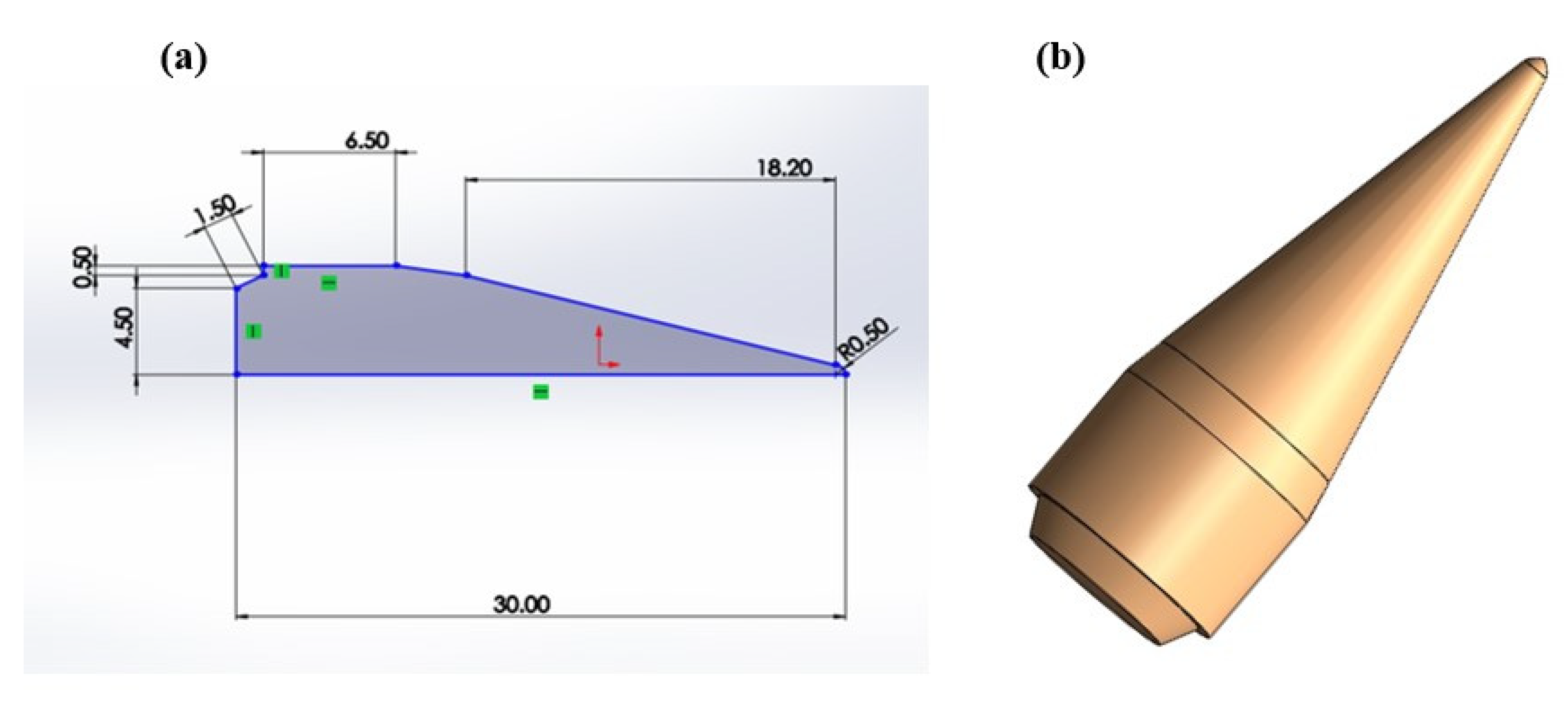
In this research work, the head of an M193 bullet was designed in SOLIDWORKS (Figure 1) and different simulations were performed in Ansys Fluent at different lengths and angles of attacks (Table 1) to analyze the drag and lift coefficient behavior. Simulations and experimental testing were performed to analyze the behavior of the drag force at three different lengths (30, 40, and 50 mm) and for three different angles of attack (30, 40, and 50 degrees).
2.3. Bullet Head (Design II)
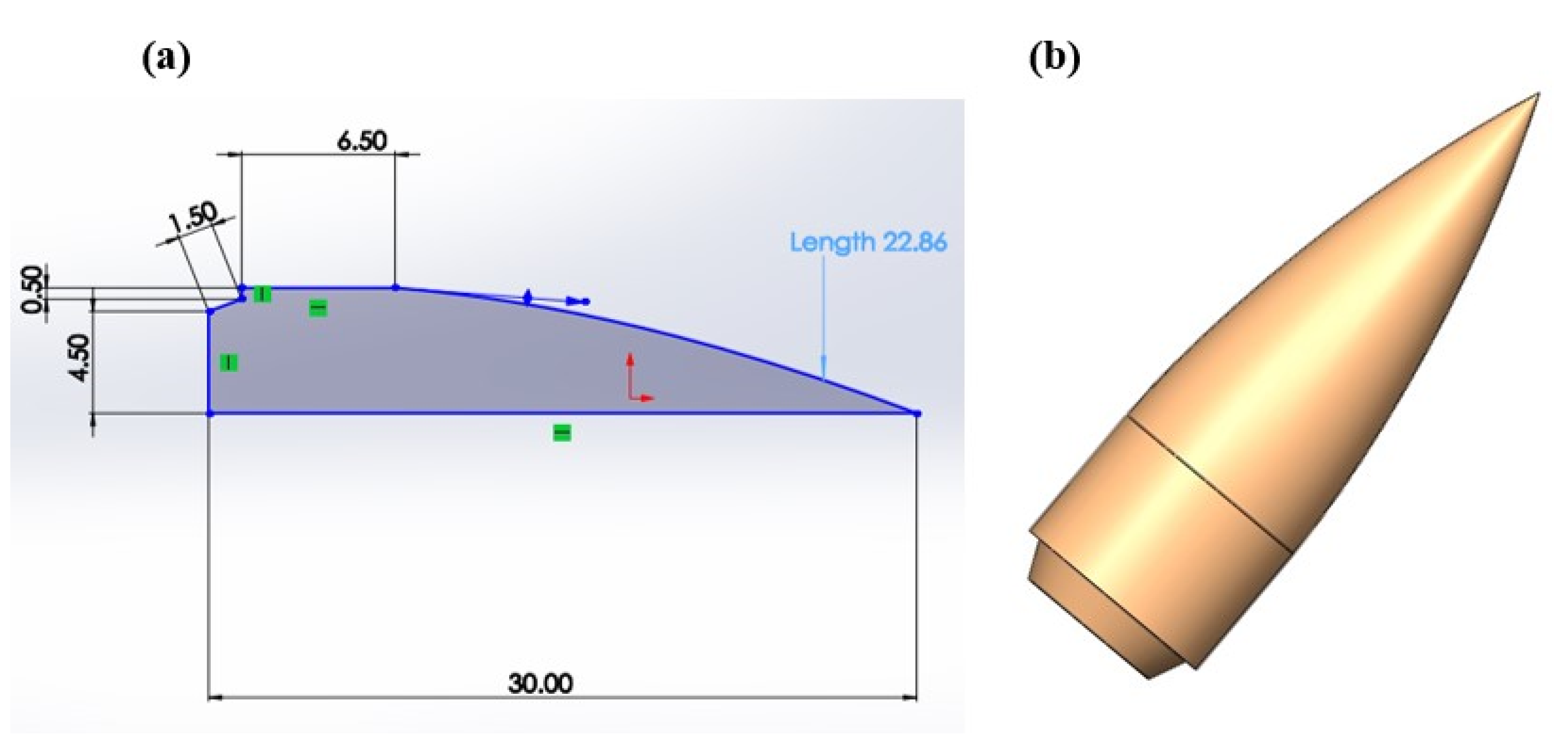
In design II, the bullet head was a modified form of design I, in which only its frontal area was decreased (Figure 2). Different numerical simulations and experimental investigations were also performed on it to analyze the behavior of drag force when reducing the frontal area. Numerical and experimental simulations were performed at only one length, i.e., 30 mm, but with three angles of attack: 30, 40, and 50 degrees (Table 2).
2.4. Experimental Model
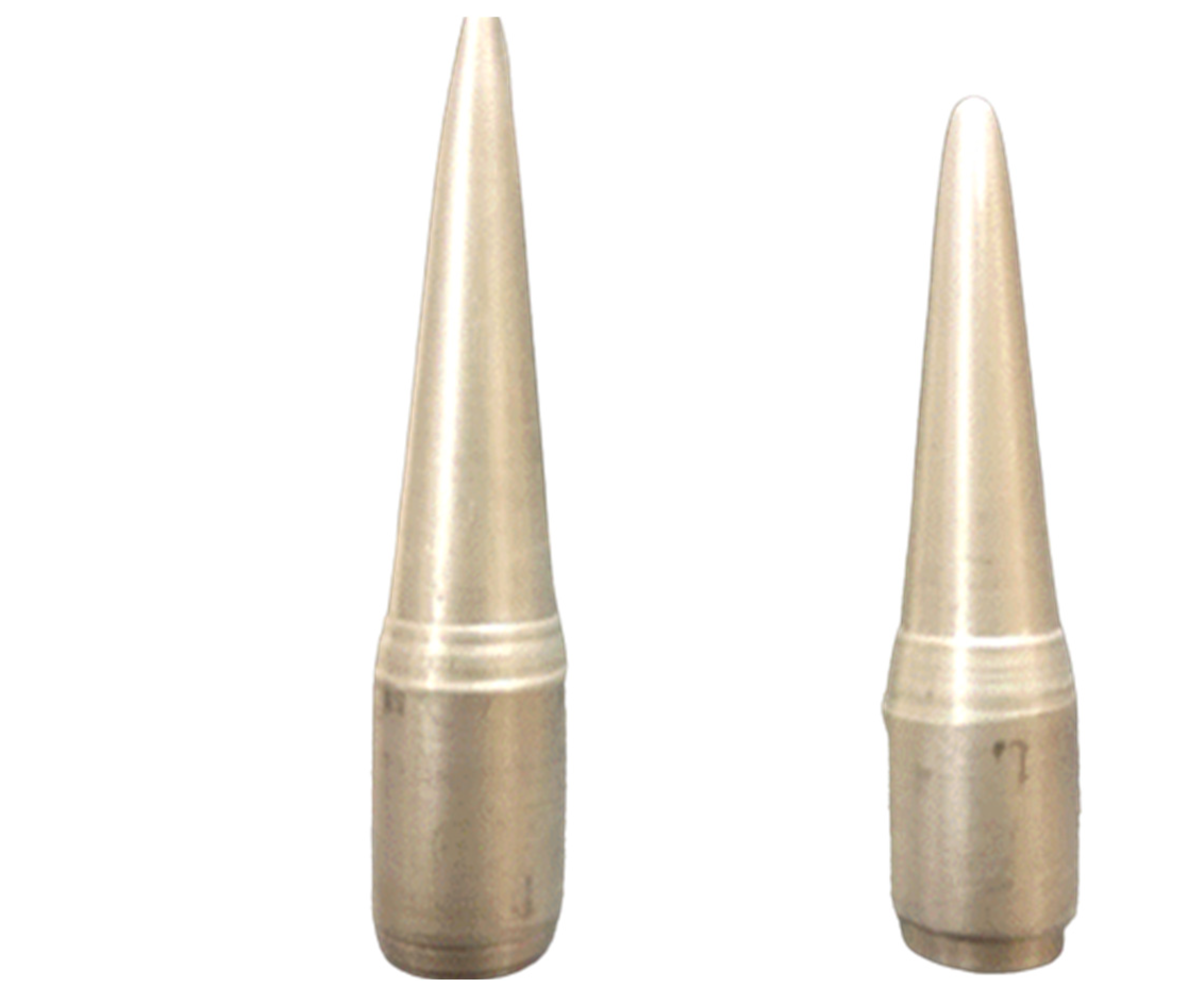
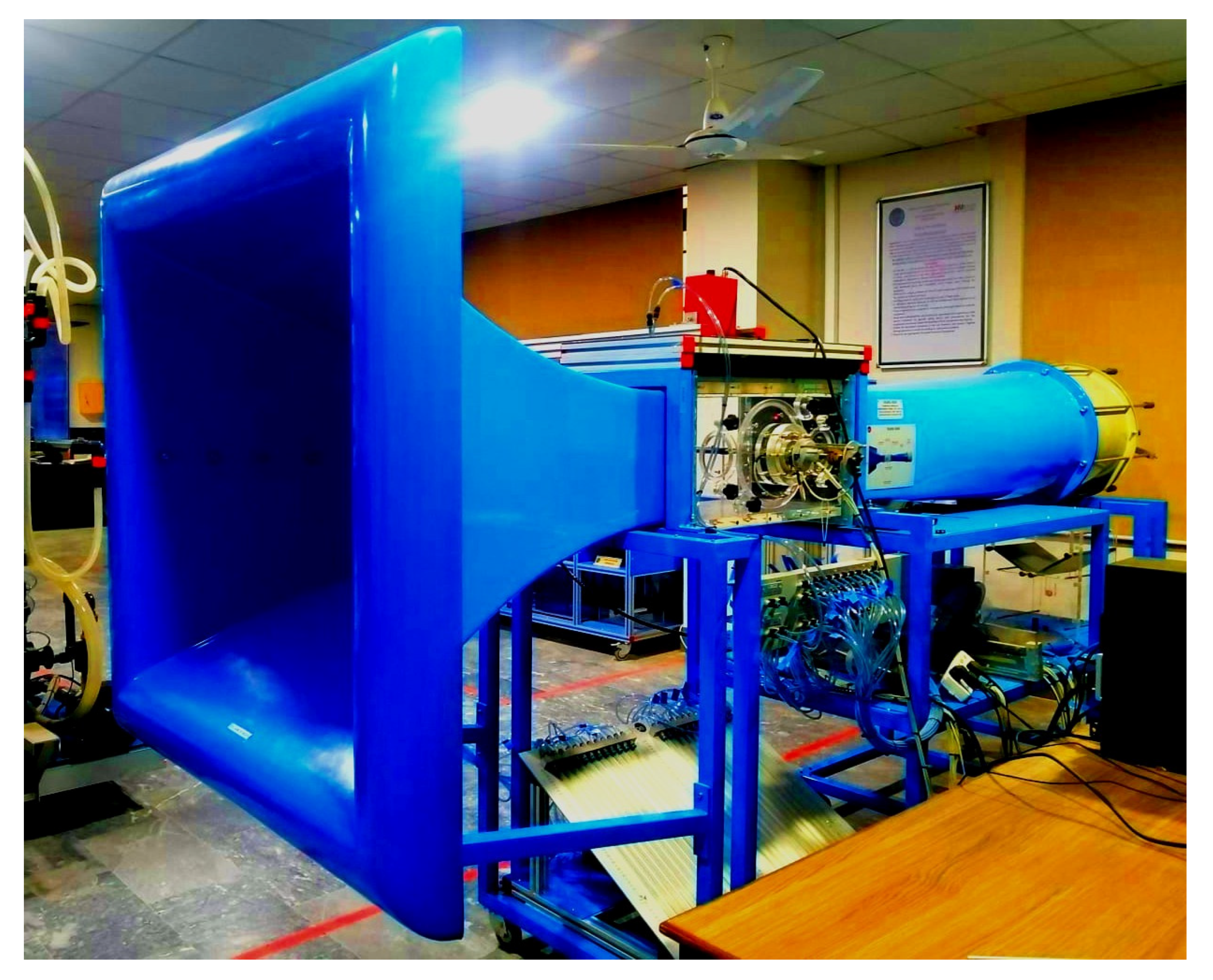
Prototypes of bullet head design I and bullet head design II were manufactured to perform the experimental testing of bullet heads (Figure 3). Aluminum was used as the material; primary machining operations such as turning, taper turning, and parting were performed using a lathe machine, whereas a radial drill machine performed the drilling operation. The wind tunnel used in the experimental investigation of bullet heads is shown in Figure 4. The details of the fabrication of the bullet heads are briefly presented in the Supplementary Materials in Figure S1.
Wind tunnel tests were performed to understand the nature of flow around the bullet head and to analyze the aerodynamic forces acting upon it. They also helped to verify the numerical simulations with the experimental results and identify the areas of improvement in the design. The TA 300/300 C (Figure 4) subsonic wind tunnel with an operating range of 0.1 to 0.9 Mach number was used to analyze the aerodynamic effects around the bullet head. The TA 300/300 C is a computer-based apparatus equipped with the SCADA operating system. Aerodynamic properties were investigated in the steady-state mode of a wind tunnel in which the fluid properties remained the same. The bullet head was clamped in the wind tunnel with the help of a thin aluminum rod inserted along the axis of the head, in the same way as in a real framework. To analyze the behavior of the flow around the bullet head precisely, the velocity of air in the wind tunnel was properly adjusted and calibrated. The complete experimental methodology is described in the Supplementary Materials, in Figures S4 and S5.
2.5. Mathematical Model and Simulations
Mathematical equations and principles required in calculating the lift and drag coefficient are described briefly. The total force that acts on a single segment of a projectile was calculated from the following equation.
where is the force, is the pressure acting at the tapping, and is the area of the projectile, calculated by using SOLIDWORKS modeling.
The pressure acting at the pattering of the projectile was calculated from the following equation.
where is the pressure, is the manometer reading, is the density of kerosene, and is the gravitational acceleration of the projectile.
As in the numerical investigation, the bullet head was sectioned into 30 segments, so the total force acting on it was calculated by adding the individual forces of all thirty segments, as illustrated below.
When the air is incident at 0° to the axis of the bullet, the only force that acts upon the bullet is the force of gravity; however, when the bullet head is subjected to air at a certain angle of attack (a) greater than 0°, the total force acting on the bullet must be divided into two components, i.e., the drag force acting along the horizontal direction and the lift force acting along the vertical direction The horizontal and vertical forces were calculated from the following set of equations.
The pressure coefficient , lift coefficient , and drag coefficient from forces were calculated from the equations given below.
where is the lift force, is the drag force, is the freestream velocity, is the air density, and is the difference between ambient and static pressure. The details of the calculation of the bullet’s total surface area are provided in the Supplementary Materials S1, and the details are provided (equations a, b) in Figures S2 and S3.
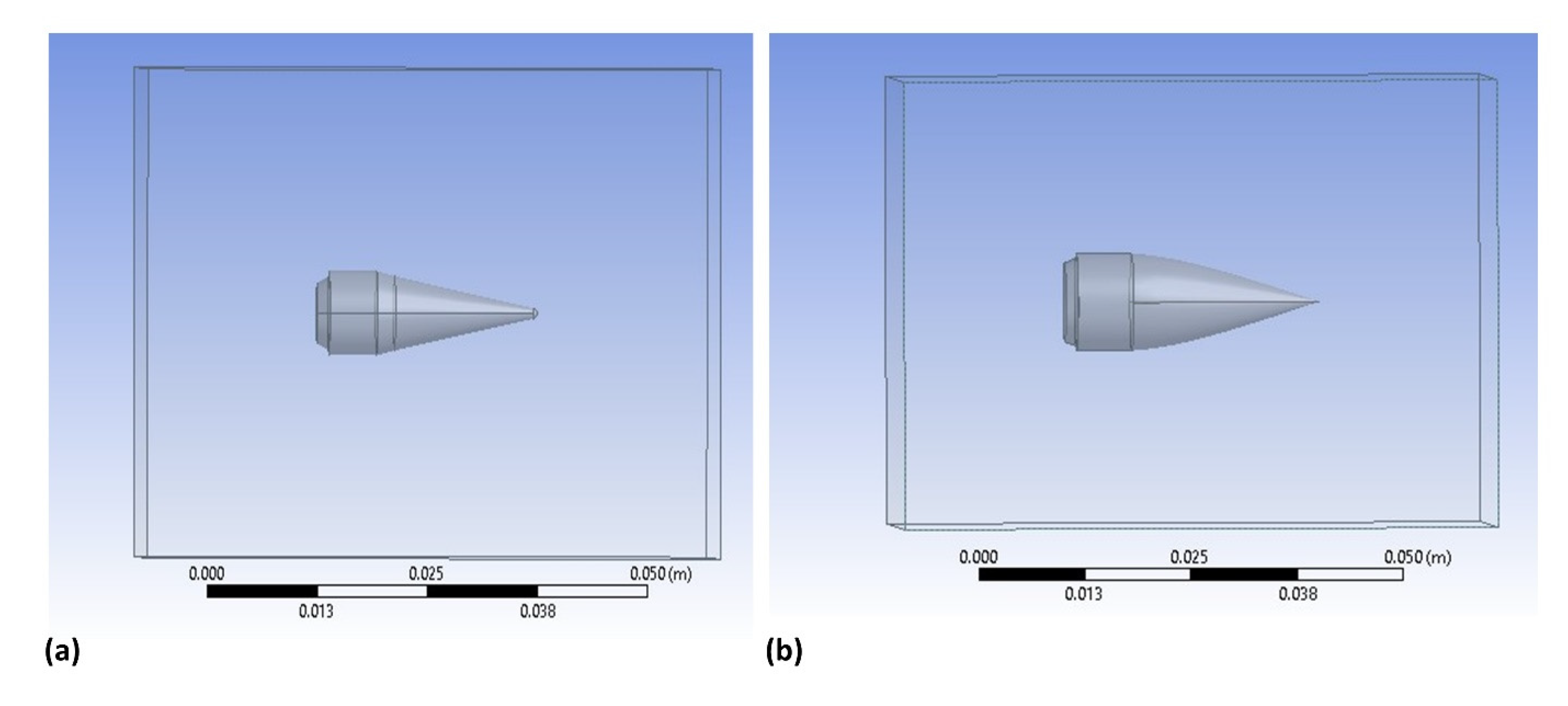
Ansys Fluent software was used to perform the numerical simulations and for the problem analysis of the studied k-e turbulence. The geometries of the bullet head were sketched in SOLIDWORKS and were imported into Ansys Fluent for the simulations. Figure 5 depicts the geometric enclosure on both the bullet geometries, required to achieve a finite volume.
The numerical simulations were performed according to the experimental conditions, where the air inlet condition was the “velocity inlet” at 5.2 m/s. The outlet condition was the “pressure outlet” at atmospheric pressure, and the remaining surface was considered a wall. Boundaries chosen for simulation were at the left, right, top, and rear, up to 10D, 10D, 10D,10D, and 15D, respectively, from the model exterior, where D is the downstream radius of the bullet head. In the simulations, a 16.0 unstructured grid was first adopted to improve the numerical simulation’s precision and a sphere influence approach was used to conceal the grid around the model.
Figure 6a shows the grid independence test for the lift and drag forces. Figure 6b shows the mesh sample for both designs. Initially, the mesh generated had 2,143,024 elements and 2,871,033 nodes for simulation, but the results were obtained in a grid dependency test as a finer mesh composed of 2,143,024 elements and 2,871,033 nodes, as compared to a coarse mesh with the number of elements of 192,991 and with 64,312 nodes. In the numerical simulations, the variation in the pressure coefficient for the finer mesh fluctuated with the coarse mesh by 0.55%, which was consistent with the dependency test. The y+ value adopted in the numerical simulations was 36; however, the y+ plot is shown in Figure S7 in the Supplementary Materials. Figure 6c shows the computational domain, which comprised the inlet, where the flow entered the domain, and the outlet, where the flow left the domain after flowing around the bullet head, while the remaining boundaries were the walls and symmetry at which the symmetrical head was placed. The geometric enclosures of design I and design II of the bullet head are shown in Figure 5. A description of the organization of the computational domain is provided in Figure S6 in the Supplementary Materials.
The flow considered in the analysis was steady and incompressible, and a pressure outlet condition was applied to the outlet. In the computational domain, the air entered with a velocity of 5.2 m/s and an air density of 1.225 kg/m3. In contrast, the viscosity of air was 0.0000178 kg/ms. The finite volume method (FVM) solver was used to solve the numerical CFD model, in which the upwind-based multidimensional linear construction approach was used. Default solver settings were selected to solve the steady-state problem. An upwind discretization scheme was used to solve the pressure, kinetic energy, and turbulence dissipation equations. In FVM, once these conditions were achieved in a controlled volume in a particular mesh, a system of linear equations was obtained that was utilized in the calculation.
3. Results and Discussion
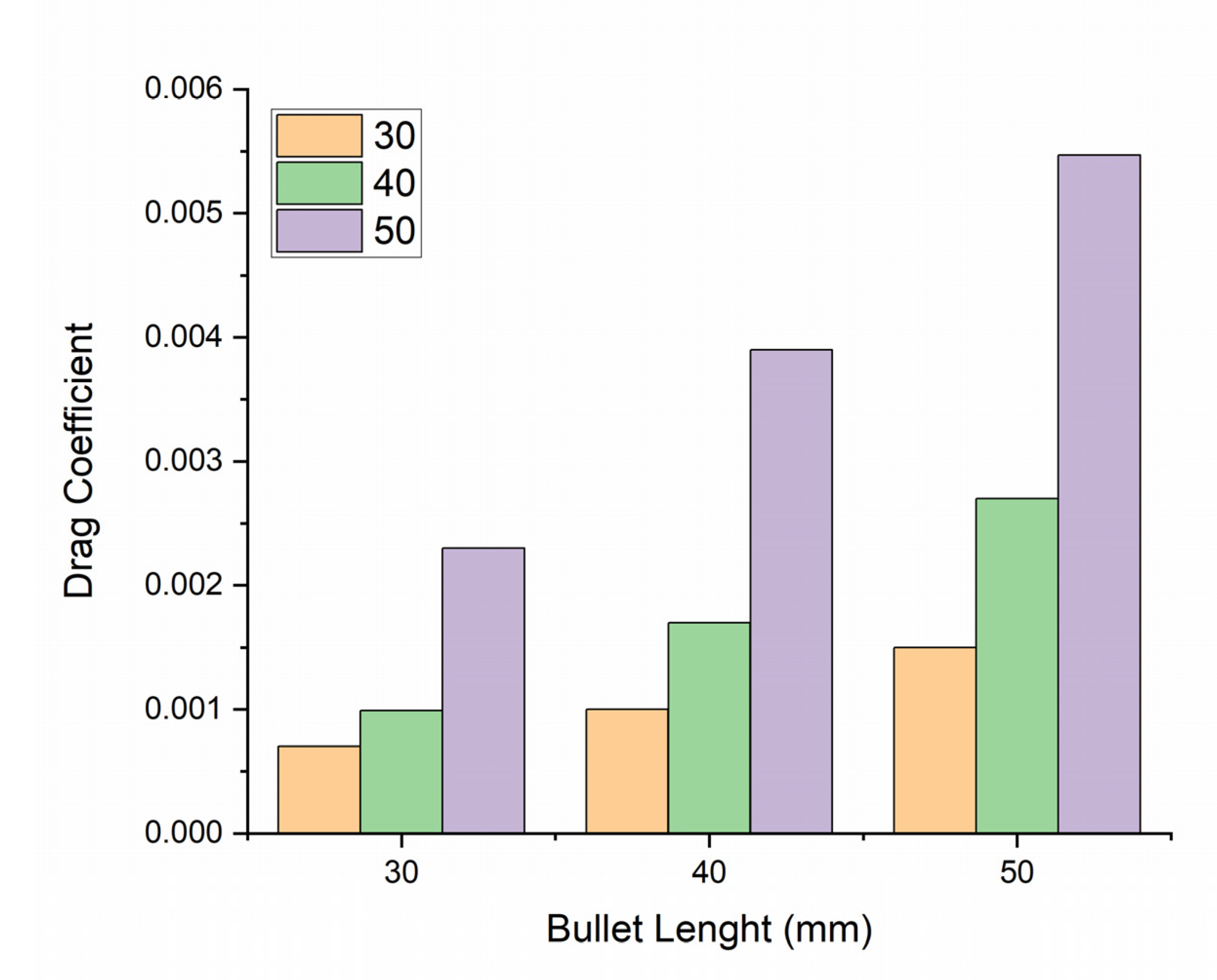
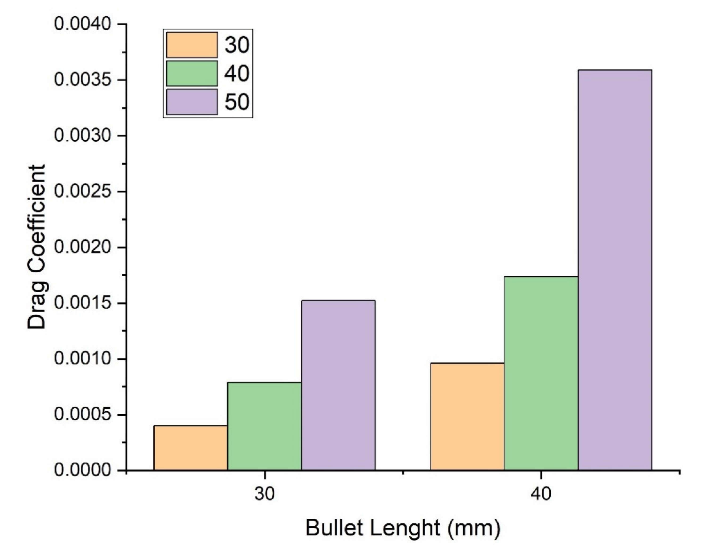
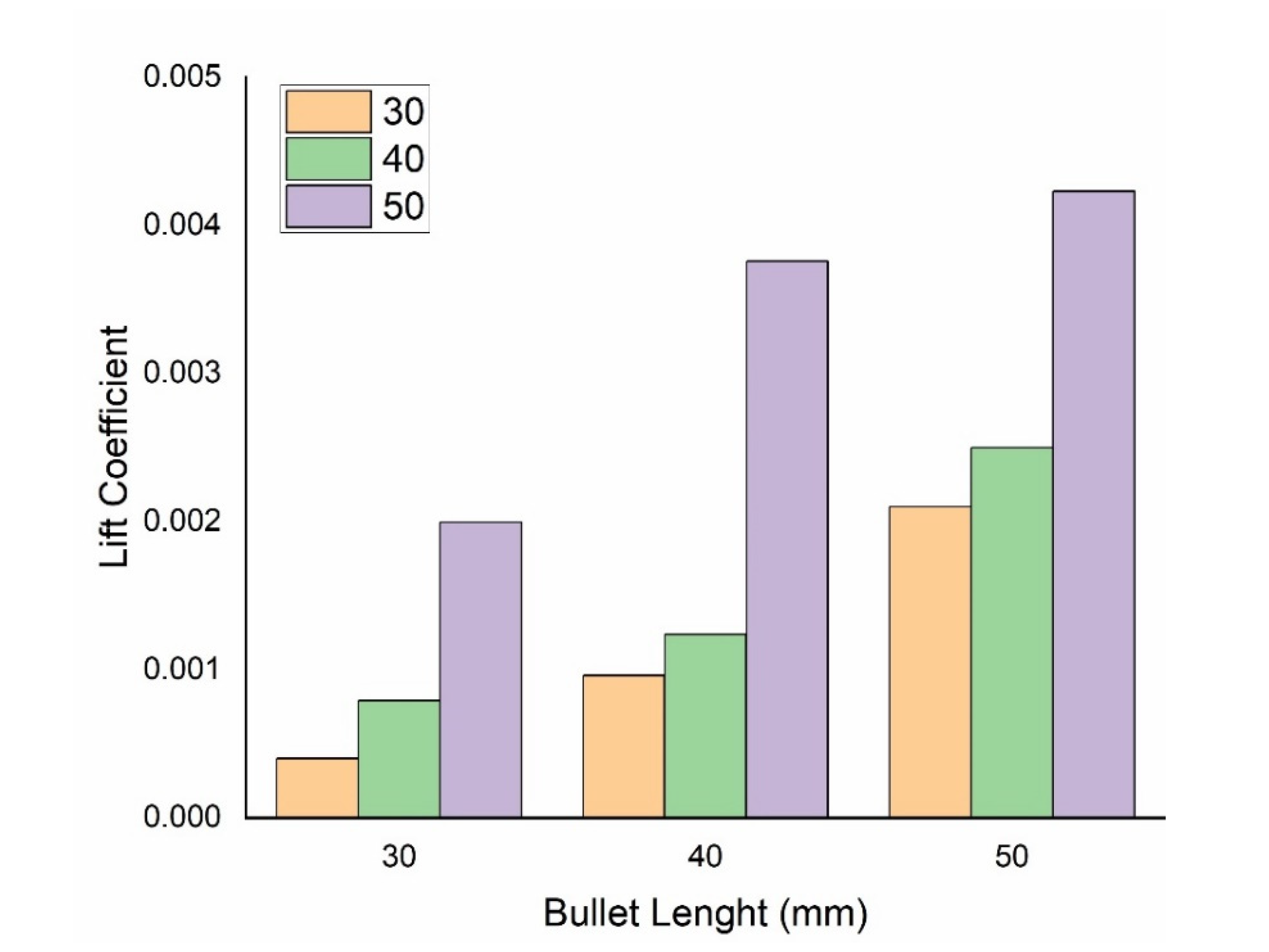
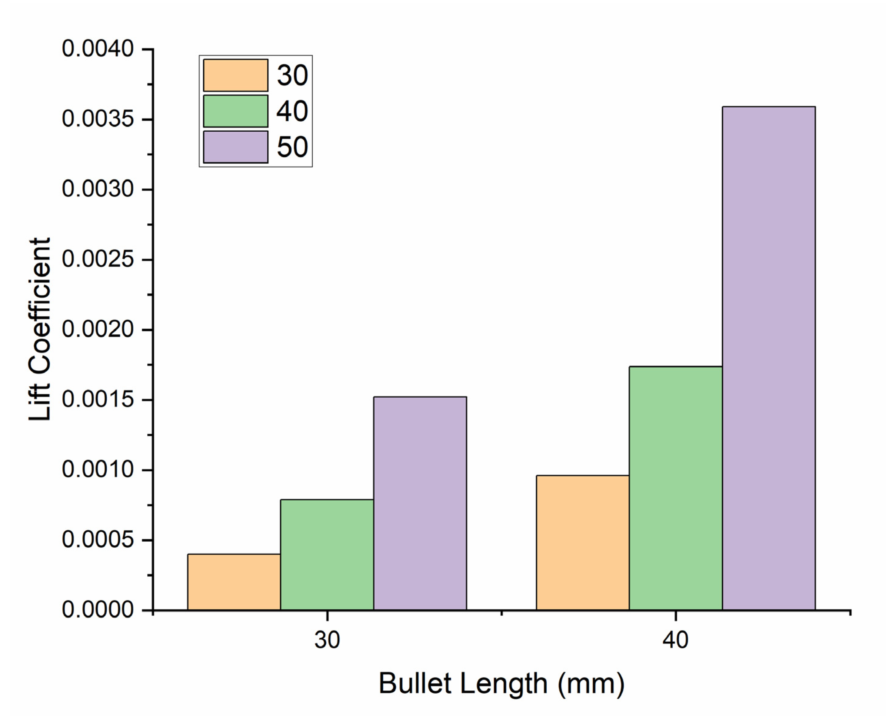
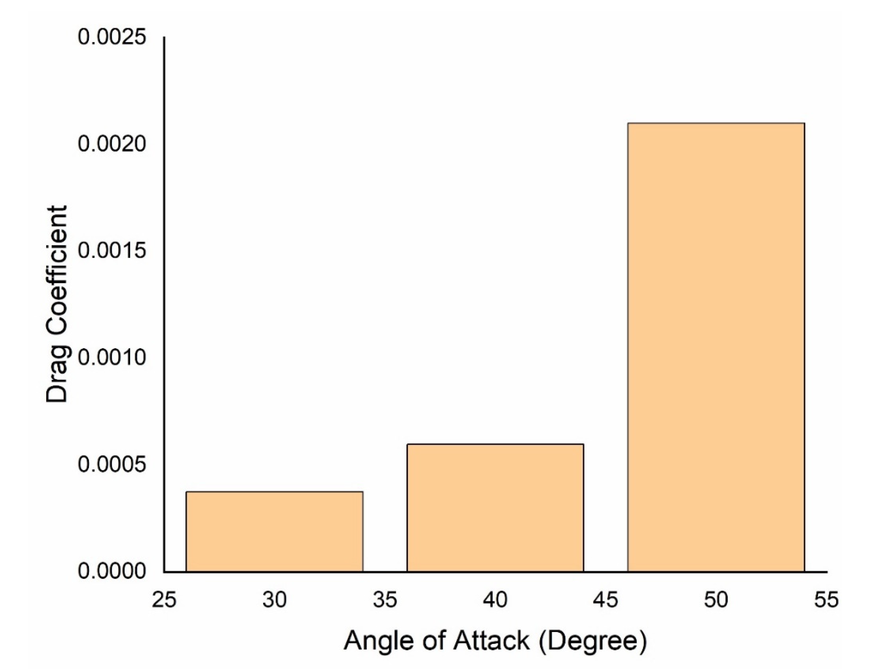
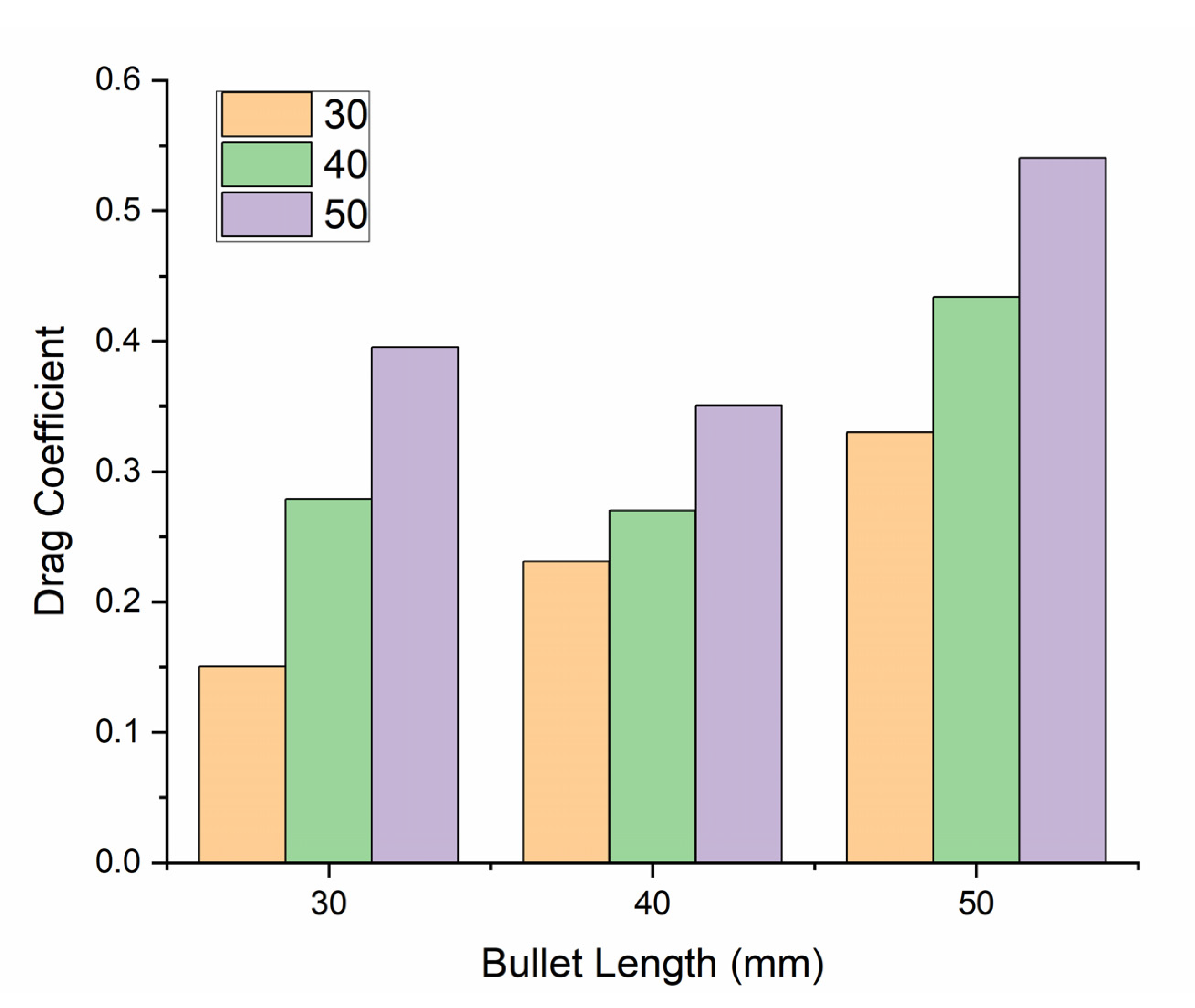
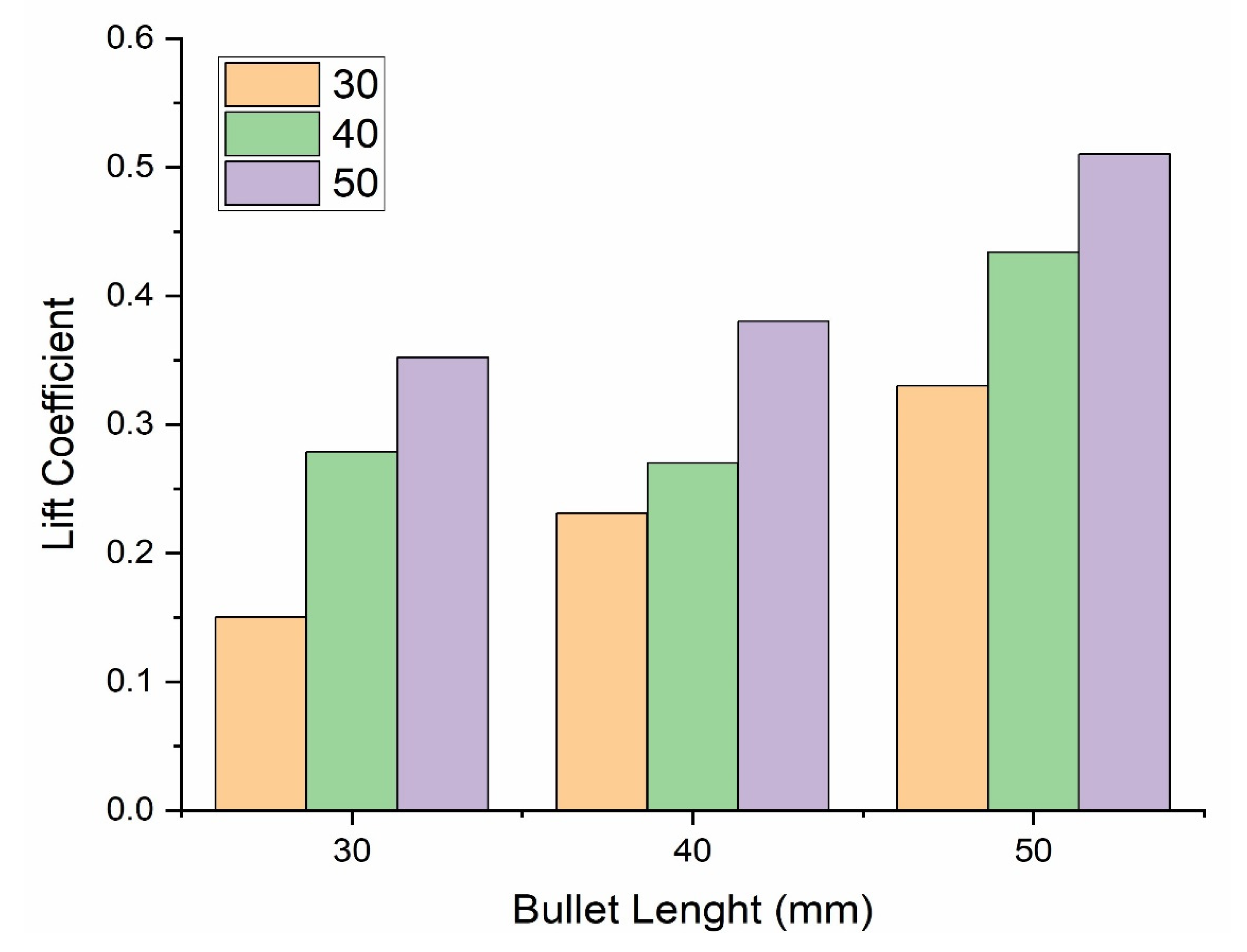
The simulated and experimental results of the drag and lift coefficients of bullet heads of 30 mm, 40 mm, and 50 mm, at different angles of attack, are shown in Figure 7, Figure 8, Figure 9 and Figure 10. The results showed that the bullet head’s drag coefficient and lift coefficient increased when enhancing the angle of attack and the span of the bullet head at a constant air velocity. The drag coefficient of the bullet head decreased when decreasing its frontal area. Simulations were performed in Ansys software, whereas experimental testing was conducted in the wind tunnel. Simulation drag and lift forces were calculated using Ansys software, and experimental drag and lift forces were calculated in the wind tunnel. The numerical and experimental values of the lift and drag coefficient are shown in Table 3 and Table 4, respectively. The abovementioned equations were used to calculate these forces’ lift and drag coefficients.
The obtained results showed that the bullet heads’ lift and drag coefficients were directly proportional to the length and angle of attack. The drag and lift coefficient increased when increasing the length and angle of attack. This is because, when increasing the angle of attack, the air resistive forces increased [29]; when increasing the length of the bullet head, its surface area increased due to their combined effect, and its drag coefficient increased.
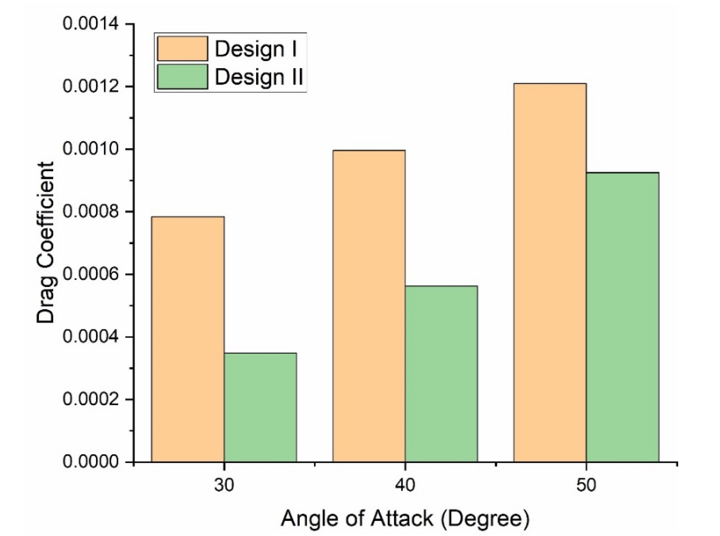
As shown in Figure 11, there was a lower drag coefficient in the case of design II compared with design I. This phenomenon could be due to the smaller frontal area [30]. The frontal area of the bullet head exerted a significant influence on the drag coefficient, and the drag coefficient decreased with the decrease in the frontal area of the bullet head. A comparison of the simulated drag coefficients of design I and design II for bullet heads at varying angles of attack is shown in Figure 12, whereas the values of the drag coefficient for design II are listed in Table 5.
The findings showed that the drag and lift coefficients of design II of the bullet head were directly proportional to the length and angle of attack.
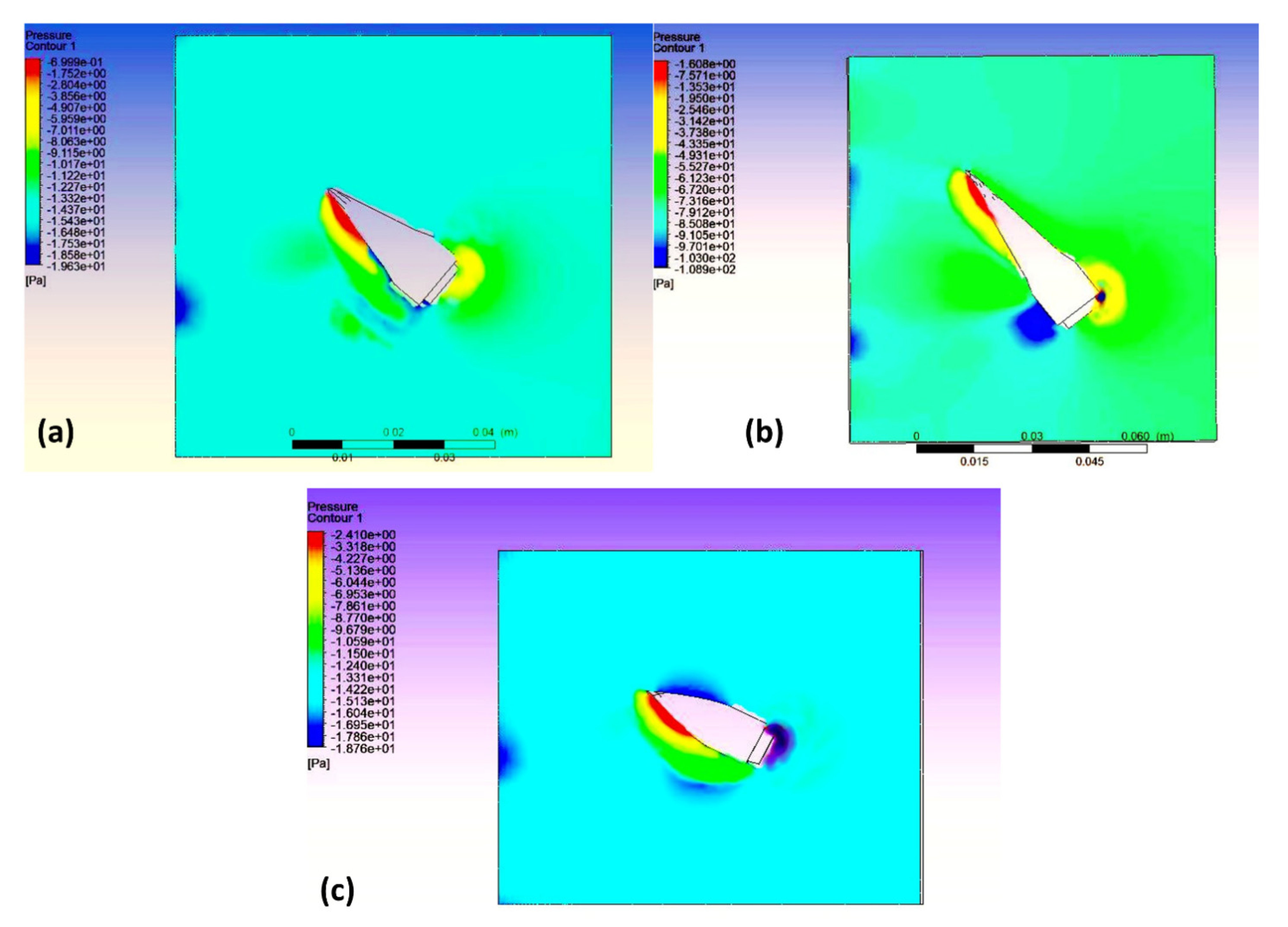
The simulated pressure contours of design I and design II are shown in Figure 13. The pressure contours showed that the pressure was more dominant at the front of the bullet head, because the frontal area determines the pressure. The pressure that is created by a ballistic impact means that the pressure is more significant at the frontal side as compared to the rear side, because the projected area subsides at the frontal side. The pressure is the resistive force per unit area, so the force exerted by the bullet on the medium must be greater than the force exerted by the medium on the bullet, as per Newton’s third law. There is a direct relationship between the projected area and the resistive drag force; the proposed geometry of the bullet head lessens the resistive drag force by decreasing the projected area and, as a result, the fluid separation point is decreased. The distribution of the pressure coefficient along the chordwise bullet length is depicted in Figure S8 in the Supplementary Materials.
In an incompressible simulation with an operating pressure of 0 Pa (to reduce rounding errors), it could be possible to achieve regions of negative pressure. This phenomenon could be due to the pressure gradient entering the Navier–Stokes equations and pressure differences driving the flow. Therefore, the low pressure inside the separated flow region relative to the system’s lowest fixed pressure might become negative. When the gauge static pressure was negative, it was revealed that it was below the operating pressure but positive (Figure 14).
The velocity streamlines of design I and design II are shown in Figure 15. The velocity streamline plot showed that the streamline was flowing over the 30 mm bullet head. The 40 mm bullet head and 50 mm bullet head showed no streamline flowing over them. Therefore, the drag forces could be higher for larger bullet heads. Design II revealed more velocity streamlines than design I; as a result, higher drag forces acted on it. The velocity was highest at the muzzle and decreased steadily due to drag. If the bullet was shot at an angle between 0 and 90 degrees relative to the horizontal ground, the trajectory formed an arch. The vertical velocity component was zero at the highest point in the arch. For a constant density flow, the velocity increased wherever the area between streamlines decreased. It could be observed that the pressure was highest at the front surface of the bullet, and the velocity was minimal.
The air speed used in this simulation was below the subsonic region; however, the results could be more accurate if the simulations were performed in the supersonic region. Therefore, the simulations were again performed in the supersonic region to analyze the behavior of the lift and drag coefficients. The values were different but the results followed the same trend: the values of the lift and drag coefficient increased when enhancing the angle of attack and the length of the bullet head [24]. Moreover, the values of the drag coefficient decreased (Figure 16) and the lift coefficient (Figure 17) increased when decreasing the frontal area of the bullet head.
The uncertainty calculation of the numerical and the experimental values is shown in Table 6.
The uncertainty in the values of the lift coefficient was greater than the uncertainty in the drag coefficient. The results have uncertainty due to the following reasons: the boundary conditions are constant in CFD and are assumed to be constant in experimentation, but, in actual scenarios, these conditions do not remain constant.
- The wind tunnel may have some adjustment errors that cause a difference between the CL (EXP) and CL (CFD).
- The wind tunnel may have blockage effects that cause a difference between the experimental and CFD coefficients.
4. Conclusions
In this research work, a numerical and experimental investigation was performed on a bullet. Similar conditions were applied in numerical and experimental testing to analyze or to measure the factors that are not possible to visualize in real time, and efforts were also made to analyze the factors on which the drag coefficient is dependent and how it should be minimized. The following are some important conclusions drawn from the study:
- The above research work focuses on the drag and lifts coefficients of a bullet head because these are the parameters on which the hitting precision and range of a bullet head are dependent.
- The above numerical and simulation results show that the lift and drag coefficients of a bullet head are directly proportional to the angle of attack and length of a bullet; when increasing these parameters, the lift and drag coefficients also increase.
- Velocity streamlines are inversely proportional to the drag coefficient because there are no streamlines at a 50 mm bullet head, due to which a large drag force act on it.
- When increasing the angle of attack, the increase in the drag coefficient is greater than the increase in the lift coefficient. Hence, we can state that these two parameters are due to the combined effect of the size, shape, and angle of attack.
- In the real-time framework, the flight of a bullet is in the supersonic region, whereas this research work focused on the simulation of the subsonic region because it presents the initial flight scenario; however, when numerical simulations were performed in the supersonic region, we observed the same trend.
- The drag coefficient of the modified design of the bullet head is smaller than the drag coefficient of the original design of the bullet head under the same conditions, because the modified design of the bullet head has a smaller projected area, so, according to the results, the drag coefficient is inversely proportional to the projected area.
The future scope of this research work is as follows:
- Numerical and experimental investigation of a bullet head will be performed in the future, in which the behavior of a bullet head will be analyzed and interpreted at multiple points in its trajectory.
- Experimental and numerical investigation of a bullet head will be performed with the optimization of its shape so that it has less drag and a greater lift coefficient.
- In the actual framework, both the wind and bullet heads are moving; to evaluate this, numerical and experimental testing can be performed in the future at different speeds.
Supplementary Materials
The following supporting information can be downloaded at: https://www.mdpi.com/article/10.3390/aerospace9120816/s1, Figure S1a. Jig and Fixture utilized in the drilling; Figure S1b. Multiple processes in the fabrication of the bullet head; Figure S2 Projected area of Design I by SOLIDWORKS.; Figure S3 Projected area of Design I by SOLIDWORKS; Figure S4. SCADA interface of the Wind Tunnel; Figure S5. Bullet head clamped in the wind tunnel; Table S1. Specifications of the Wind Tunnel T300/300C; Figure S6(a) Enclosure accomplishing (b) Boolean creation (c) Applying symmetry (d) Applying the boundary conditions; Figure S7. Line plot of the y+ values a; Figure S8. Distribution of the pressure coefficient along the chordwise bullet length.
Author Contributions
Conceptualization, A.K. and I.S.; methodology A.K., I.S. and U.K.u.Z.; software, U.K.u.Z. and M.W.; writing—original draft preparation, A.K. and I.S.; writing—review and editing, A.K., I.S. and S.A.; supervision, I.S.; project administration, M.W.; funding acquisition, D.-W.J. and S.A. All authors have read and agreed to the published version of the manuscript.
Funding
This work was supported by the Korea Institute of Energy Technology Evaluation and Planning (KETEP) grant funded by the Korea government (MOTIE) (20206310100050, A development of remanufacturing technology on the grinding system of complex-function for high-precision).
Conflicts of Interest
The authors declare that they have no known competing financial interests or personal relationships that could have seemed to affect the work reported in this paper.
References
- Rhee, P.M.; Moore, E.E.; Joseph, B.; Tang, A.; Pandit, V.; Vercruysse, G. Gunshot wounds: A review of ballistics, bullets, weapons, and myths. J. Trauma Acute Care Surg. 2016, 80, 853–867. [Google Scholar] [CrossRef] [PubMed] [Green Version]
- Bateman, M.J.K.; Force, U.A. Maximizing Engagement Area Lethality. Mil. Rev. 2022. [Google Scholar]
- Ahmad, G.; Alanazi, S.; Alruwaili, M.; Ahmad, F.; Khan, M.A.; Abbas, S.; Tabassum, N. Intelligent Ammunition Detection and Classification System Using Convolutional Neural Network; Tech Science Press: Henderson, NV, USA, 2021; Volume 2, p. 340. [Google Scholar]
- Carlucci, D.E. Ballistics: Theory and Design of Guns and Ammunition; CRC Press: Boca Raton, FL, USA, 2007. [Google Scholar]
- Zamanian, S.; Terranova, B.; Shafieezadeh, A. Significant variables affecting the performance of concrete panels impacted by wind-borne projectiles: A global sensitivity analysis. Int. J. Impact Eng. 2020, 144, 103650. [Google Scholar] [CrossRef]
- Pai, A.; Kini, C.R.; Shenoy, S. Development of materials and structures for shielding applications against Blast and Ballistic impact: A Detailed Review. Thin-Walled Struct. 2022, 179, 109664. [Google Scholar] [CrossRef]
- Rahman, M.R. Computational Analysis of Aerodynamic Parameters for Supersonic Artillery Projectiles International journal of mechanical engineering. J. Mech. Civ. Eng. 2020, 6, 1–18. [Google Scholar]
- Lin, L.; Ju, R. Analysis and Research on the Impact of Bullet Head Eccentricity on Air Resistance. In Journal of Physics: Conference Series; IOP Publishing: Bristol, UK, 2020; p. 012064. [Google Scholar]
- Yang, Y.-L.; Guo, R.; Liu, R.-Z.; Chen, L.; Xing, B.Y.; Zhao, B.B. Quasi-steady aerodynamic characteristics of terminal sensitive bullets with short cylindrical portion. Def. Technol. 2021, 17, 633–649. [Google Scholar] [CrossRef]
- Yang, Y.; Guo, R.; Liu, R.; Guo, Z.; Qu, Y.; Chen, L. Numerical analysis on aerodynamic characteristics of short cylindrical terminal-sensitive bullet. Vibroengineering Procedia 2018, 18, 150–156. [Google Scholar] [CrossRef] [Green Version]
- Bolonkin, A. Long distance bullets and shells. Int. J. Aerosp. Sci. 2013, 2, 29–36. [Google Scholar]
- Novak, L.; Bajcar, T.; Širok, B.; Orbanić, A.; Bizjan, B. Investigation of vortex shedding from an airfoil by computational fluid dynamics simulation and computer-aided flow visualization. Therm. Sci. 2018, 22, 3023–3033. [Google Scholar] [CrossRef]
- Jang, Y.; Huh, J.; Lee, N.; Lee, S.; Park, Y. Comparative study on the prediction of aerodynamic characteristics of aircraft with turbulence models. Int. J. Aeronaut. Space Sci. 2018, 19, 13–23. [Google Scholar] [CrossRef]
- Dali, M.A.; Jaramaz, S. Optimization of artillery projectiles base drag reduction using hot base flow. Therm. Sci. 2019, 23, 353–364. [Google Scholar] [CrossRef]
- Wessam, M.; Chen, Z. Flow field investigations and aerodynamic characteristics of artillery projectile. In Proceedings of the International Conference of Electrical, Automation and Mechanical Engineering (EAME 2015), Phuket, Thailand, 26–27 July 2015. [Google Scholar]
- Burris, J.L.; Hester, B.C.; Mamola, K.C. The two-bullet problem with constant magnitude drag force. Phys. Teach. 2018, 56, 340–343. [Google Scholar] [CrossRef]
- Munir, A.; Aved, A.; Blasch, E. Situational Awareness: Techniques, Challenges, and Prospects. AI 2022, 3, 55–77. [Google Scholar] [CrossRef]
- Sahoo, S.; Laha, M. Coefficient of drag and trajectory simulation of 130 mm supersonic artillery shell with recovery plug or fuze. Def. Sci. J. 2014, 64, 502. [Google Scholar] [CrossRef]
- Bhuiyan, N.; Baghel, A.; Wilson, J. A sustainable continuous improvement methodology at an aerospace company. Int. J. Product. Perform. Manag. 2006, 4, 498. [Google Scholar] [CrossRef]
- Suliman, M.; Mahmoud, O.; Al-Sanabawy, M.; Abdel-Hamid, O.E. Computational investigation of base drag reduction for a projectile at different flight regimes. In International Conference on Aerospace Sciences and Aviation Technology; The Military Technical College: Cairo, Eqypt, 2009; pp. 1–13. [Google Scholar]
- Uddin, M.N.; Mostofa, G.; Rana, M.S. Numerical Analysis of Drag and Lift Forces Acting on Long Range Projectiles. Int. J. Acad. Res. Reflect. 2021, 9, 15–27. [Google Scholar]
- Ahmed, M.; Qin, N. Recent advances in the aerothermodynamics of spiked hypersonic vehicles. Prog. Aerosp. Sci. 2011, 47, 425–449. [Google Scholar] [CrossRef]
- Xiao, S.; Hu, K.; Huang, B.; Deng, H.; Ding, X. A review of research on the mechanical design of hoverable flapping wing micro-air vehicles. J. Bionic Eng. 2021, 18, 1–20. [Google Scholar] [CrossRef]
- Truscott, T.; Techet, A.; Beal, D. Shallow angle water entry of ballistic projectiles. In Proceedings of the 7th International Symposium on Cavitation, Ann Arbor, MI, USA, 16–20 August 2009. [Google Scholar]
- Susu, L.; Cheng, X.; Yaoke, W.; Xiaoyun, Z. A new motion model of rifle bullet penetration into ballistic gelatin. Int. J. Impact Eng. 2016, 93, 1–10. [Google Scholar] [CrossRef]
- Götten, F.; Havermann, M.; Braun, C.; Gómez, F.; Bil, C. On the applicability of empirical drag estimation methods for unmanned air vehicle design. In Proceedings of the 2018 Aviation Technology, Integration, and Operations Conference, Atlanta, GA, USA, 25–29 June 2018; p. 3192. [Google Scholar]
- Sethuraman, V.; Rajendran, P.; Khan, S.A. Base and wall pressure control using cavities and ribs in suddenly expanded flows-an overview. J. Adv. Res. Fluid Mech. Therm. Sci. 2020, 66, 120–134. [Google Scholar]
- Khan, A.; Rajendran, P.; Sidhu, J.S.S. Passive Control of Base Pressure: A Review. Appl. Sci. 2021, 11, 1334. [Google Scholar] [CrossRef]
- Patel, K.S.; Patel, S.B.; Patel, U.B.; Ahuja, A.P. CFD Analysis of an Aerofoil. Int. J. Eng. Res. 2014, 3, 154–158. [Google Scholar] [CrossRef]
- Seifert, J. A review of the Magnus effect in aeronautics. Prog. Aerosp. Sci. 2012, 55, 17–45. [Google Scholar] [CrossRef]
Figure 1.
Dimensions (a) and geometry (b) of the bullet head in design I.

Figure 2.
Dimensions (a) and geometry (b) of the bullet head in design II.

Figure 3.
Prototypes of bullet head design I (left) and design II (right).

Figure 4.
Wind tunnel used in experimental investigation of bullet heads.

Figure 5.
Geometric enclosure of (a) design I and (b) design II of the bullet head in Ansys software.
Figure 5.
Geometric enclosure of (a) design I and (b) design II of the bullet head in Ansys software.

Figure 6.
(a) Mesh independence test for lift and drag; (b) mesh diagrams of design I and design II of the bullet head; (c) computational domain.
Figure 6.
(a) Mesh independence test for lift and drag; (b) mesh diagrams of design I and design II of the bullet head; (c) computational domain.

Figure 7.
Simulated values of drag coefficient of 30 mm, 40 mm, and 50 mm bullet heads (design I) at angle of attack.
Figure 7.
Simulated values of drag coefficient of 30 mm, 40 mm, and 50 mm bullet heads (design I) at angle of attack.

Figure 8.
Experimental values of drag coefficient of 30 mm and 40 mm bullet heads (design I) at angle of attack.
Figure 8.
Experimental values of drag coefficient of 30 mm and 40 mm bullet heads (design I) at angle of attack.

Figure 9.
Simulated values of lift coefficient of 30 mm, 40 mm, and 50 mm bullet heads (design I) at angle of attack.
Figure 9.
Simulated values of lift coefficient of 30 mm, 40 mm, and 50 mm bullet heads (design I) at angle of attack.

Figure 10.
Experimental values of lift coefficient of 30 mm, and 40 mm bullet heads (design I) at angle of attack.
Figure 10.
Experimental values of lift coefficient of 30 mm, and 40 mm bullet heads (design I) at angle of attack.

Figure 11.
Simulated drag coefficient of bullet head (design II) at angle of attack.

Figure 12.
Comparison of simulated values of drag coefficient of design I and Design II of bullet heads at angle of attack.
Figure 12.
Comparison of simulated values of drag coefficient of design I and Design II of bullet heads at angle of attack.

Figure 13.
Pressure contour of (a) design I (105 mm) of bullet head at 30° angle of attack, (b) design I (130 mm) of bullet head at 40° angle of attack, and (c) design II (105 mm) of bullet head at 30° angle of attack.
Figure 13.
Pressure contour of (a) design I (105 mm) of bullet head at 30° angle of attack, (b) design I (130 mm) of bullet head at 40° angle of attack, and (c) design II (105 mm) of bullet head at 30° angle of attack.

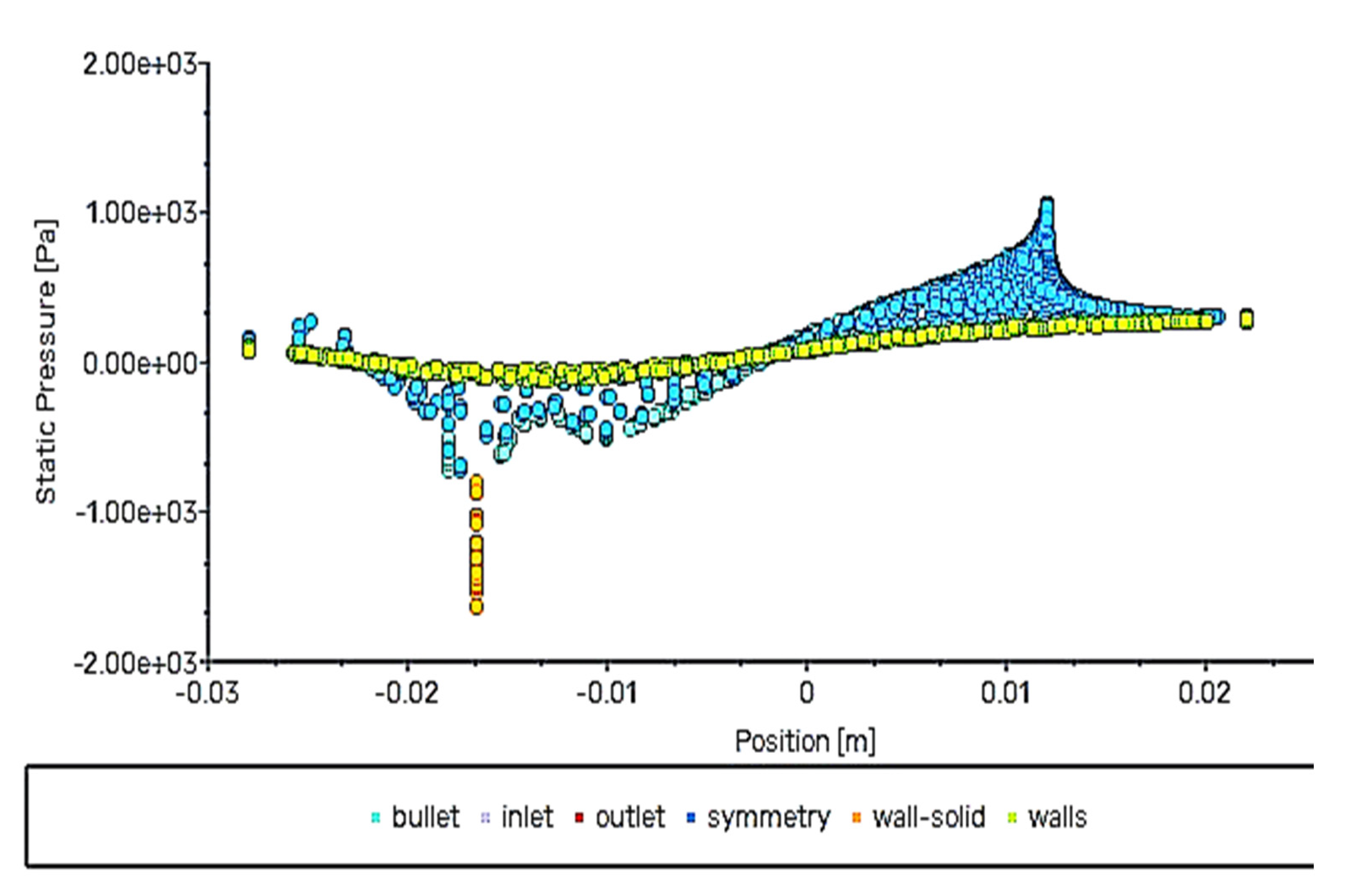
Figure 14.
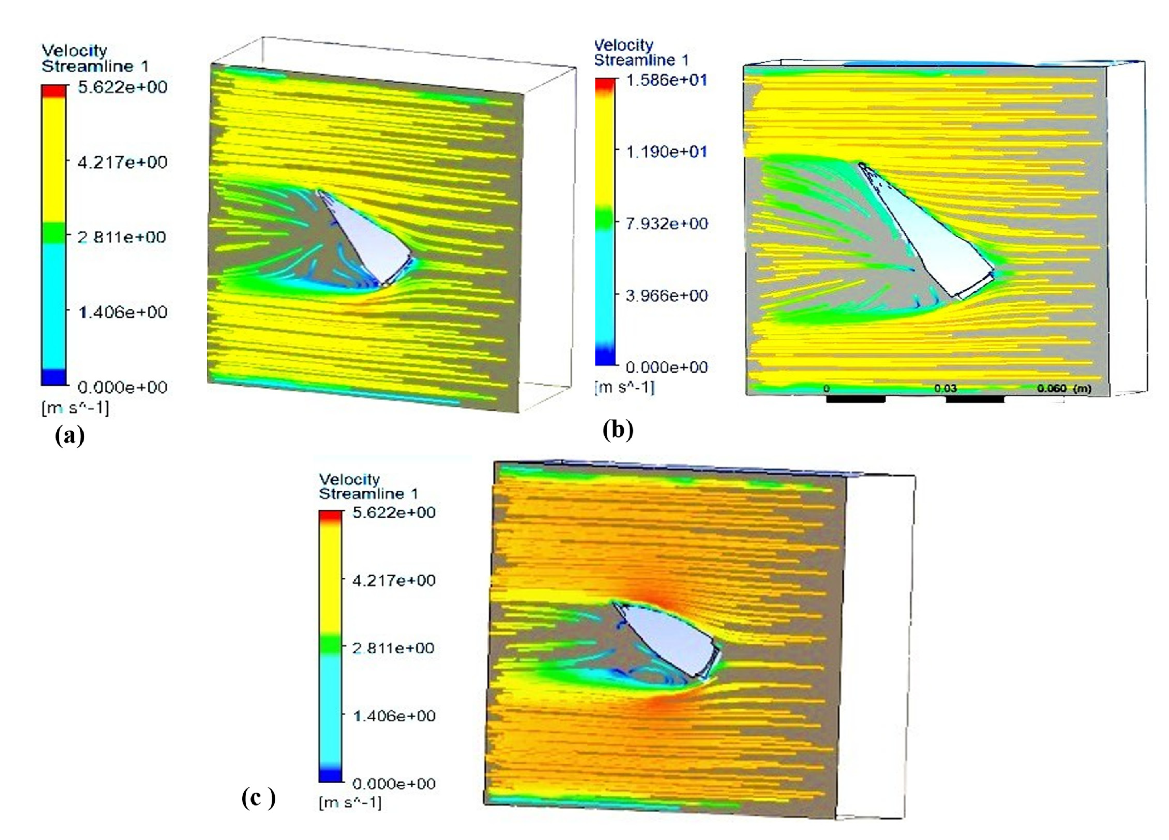
The plot between static pressure and position.

Figure 15.
Velocity streamlines of (a) design I (30 mm) of bullet head at 30° angle of attack, (b) design I (40 mm) of bullet heat at 40° angle of attack, and (c) design II (30 mm) of bullet head at a 30° angle of attack.
Figure 15.
Velocity streamlines of (a) design I (30 mm) of bullet head at 30° angle of attack, (b) design I (40 mm) of bullet heat at 40° angle of attack, and (c) design II (30 mm) of bullet head at a 30° angle of attack.

Figure 16.
Simulated value of the drag coefficient of bullet head (design II) at supersonic speed at angle of attack.
Figure 16.
Simulated value of the drag coefficient of bullet head (design II) at supersonic speed at angle of attack.

Figure 17.
Simulated value of lift coefficient of bullet head (design II) at supersonic speed at angle of attack.
Figure 17.
Simulated value of lift coefficient of bullet head (design II) at supersonic speed at angle of attack.


Table 1.
Conditions of bullet head in design I.
| Bullet Head Size (mm) | AOA (Degree) | Air Velocity (m/s) | Tapping Points (mm) | Area of the Bullet Head (mm2) |
|---|---|---|---|---|
| 30 | 30, 40, 50 | 5.2 | 30 | 902.4 |
| 40 | 30, 40, 50 | 5.2 | 30 | 1108 |
| 50 | 30, 40, 50 | 5.2 | 30 | 1148.5 |
Table 2.
Conditions of bullet head in design II.
| Bullet Size (mm) | AOA (Degree) | Air Velocity (m/s) | Tapping Points (mm) | Area of the Bullet Head (mm2) |
|---|---|---|---|---|
| 30 mm | 30, 40, 50 | 5.2 | 30 | 629.5 |
Table 3.
Simulated and experimental values of drag coefficient of bullet heads of 30 mm, 40 mm, and 50 mm at varying angles of attack.
Table 3.
Simulated and experimental values of drag coefficient of bullet heads of 30 mm, 40 mm, and 50 mm at varying angles of attack.
| Angle of Attack (Degrees) | 30 mm (Simulation) | 40 mm (Simulation) | 50 mm (Simulation) | 30 mm (Experimental) | 40 mm (Experimental) |
|---|---|---|---|---|---|
| 30 | 0.000720 | 0.000820 | 0.003987 | 0.000732 | 0.000897 |
| 40 | 0.000825 | 0.002045 | 0.004091 | 0.000900 | 0.002990 |
| 50 | 0.001145 | 0.003235 | 0.008957 | 0.001681 | 0.003871 |
Table 4.
Simulated and experimental values of lift coefficient of bullet heads of 30 mm, 40 mm, and 50 mm at varying angles of attack.
Table 4.
Simulated and experimental values of lift coefficient of bullet heads of 30 mm, 40 mm, and 50 mm at varying angles of attack.
| Angle of Attack (Degrees) | 30 mm (Simulation) | 40 mm (Simulation) | 50 mm (Simulation) | 30 mm (Experimental) | 40 mm (Experimental) |
|---|---|---|---|---|---|
| 30 | 0.000170 | 0.000370 | 0.002287 | 0.000260 | 0.000463 |
| 40 | 0.000221 | 0.000444 | 0.005591 | 0.000349 | 0.000598 |
| 50 | 0.001545 | 0.002835 | 0.003051 | 0.002168 | 0.003309 |
Table 5.
Simulated and experimental values of drag coefficient of design II of bullet heads at varying angles of attack.
Table 5.
Simulated and experimental values of drag coefficient of design II of bullet heads at varying angles of attack.
| Angle of Attack (Degrees) | 30 mm (Simulation) | 30 mm (Experimental) |
|---|---|---|
| 30 | 0.000416 | 0.000598 |
| 40 | 0.000489 | 0.000672 |
| 50 | 0.000522 | 0.000921 |
Table 6.
Uncertainty calculation of both the geometries of the bullet head.
| Normal Section | Dimpled Section |
|---|---|
| CFD | CFD |
| CL = 0.0002207 | CL = 0.000354 |
| CD = 0.00031 | CD = 0.000265 |
| Experimental | Experimental |
| CL = 0.000278 | CL = 0.000391 |
| CD = 0.00037 | CD = 0.000256 |
| Uncertainty | Uncertainty |
|
|
|
|
Publisher’s Note: MDPI stays neutral with regard to jurisdictional claims in published maps and institutional affiliations. |
© 2022 by the authors. Licensee MDPI, Basel, Switzerland. This article is an open access article distributed under the terms and conditions of the Creative Commons Attribution (CC BY) license (https://creativecommons.org/licenses/by/4.0/).
Share and Cite
MDPI and ACS Style
Khan, A.; Shah, I.; Aziz, S.; Waqas, M.; Zaman, U.K.u.; Jung, D.-W. Numerical and Experimental Analysis of Drag and Lift Forces on a Bullet Head. Aerospace 2022, 9, 816. https://doi.org/10.3390/aerospace9120816
AMA Style
Khan A, Shah I, Aziz S, Waqas M, Zaman UKu, Jung D-W. Numerical and Experimental Analysis of Drag and Lift Forces on a Bullet Head. Aerospace. 2022; 9(12):816. https://doi.org/10.3390/aerospace9120816
Chicago/Turabian StyleKhan, Abdullah, Imran Shah, Shahid Aziz, Muhammad Waqas, Uzair Khaleeq uz Zaman, and Dong-Won Jung. 2022. "Numerical and Experimental Analysis of Drag and Lift Forces on a Bullet Head" Aerospace 9, no. 12: 816. https://doi.org/10.3390/aerospace9120816
Note that from the first issue of 2016, this journal uses article numbers instead of page numbers. See further details here.