Article

A Safety-Focused System Architecting Framework for the Conceptual Design of Aircraft Systems

by
Andrew K. Jeyaraj
1,* and
Susan Liscouët-Hanke
2
1
Department of Mechanical, Industrial, and Aerospace Engineering, Concordia University, 1455 Boul. de Maisonneuve Ouest, Montreal, QC H3G 1M8, Canada
2
Department of Mechanical, Industrial and Aerospace Engineering, Concordia Institute of Aerospace Design and Innovation, Concordia University, 1455 Boul. de Maisonneuve Ouest, Montreal, QC H3G 1M8, Canada
*
Author to whom correspondence should be addressed.
Aerospace 2022, 9(12), 791; https://doi.org/10.3390/aerospace9120791
Submission received: 8 October 2022 / Revised: 26 November 2022 / Accepted: 27 November 2022 / Published: 3 December 2022
(This article belongs to the Special Issue Aerospace System Design)

Abstract

:
To reduce the environmental impact of aviation, aircraft manufacturers develop novel aircraft configurations and investigate advanced systems technologies. These new technologies are complex and characterized by electrical or hybrid-electric propulsion systems. Ensuring that these complex architectures are safe is paramount to enabling the certification and entry into service of new aircraft concepts. Emerging techniques in systems architecting, such as using model-based systems engineering (MBSE), help deal with such complexity. However, MBSE techniques are currently not integrated with the overall aircraft conceptual design, using automated multidisciplinary design analysis and optimization (MDAO) techniques. Current MDAO frameworks do not incorporate the various aspects of system safety assessment. The industry is increasingly interested in Model-Based Safety Assessment (MBSA) to improve the safety assessment process and give the safety engineer detailed insight into the failure characteristics of system components. This paper presents a comprehensive framework to introduce various aspects of safety assessment in conceptual design and MDAO, also considering downstream compatibility of the system architecting and safety assessment process. The presented methodology includes specific elements of the SAE ARP4761 safety assessment process and adapts them to the systems architecting process in conceptual design. The proposed framework also introduces a novel safety-based filtering approach for large system architecture design spaces. The framework’s effectiveness is illustrated with examples from applications in recent collaborative research projects with industry and academia. The work presented in this paper contributes to increasing maturity in conceptual design studies and enables more innovation by opening the design space while considering safety upfront.

1. Introduction

The safe and reliable operation of aircraft is the outcome of a rigorous aircraft safety assessment carried out by large interdisciplinary teams during the aircraft design process. Significant efforts are applied to identify, classify, and mitigate failure scenarios and quantitatively establish that an aircraft is safe. The safety of future aircraft configurations and system architectures, particularly complex and novel concepts such as hybrid-electric, distributed electric, and hydrogen-powered aircraft, needs to be the same or even higher than their conventional counterparts. Furthermore, understanding the impact of safety and certification regulations on the design of the aircraft early in the development process is crucial to establishing a development pipeline for novel aircraft.
Hybrid-electric, distributed-electric, and all-electric aircraft are characterized by a higher integration between the propulsion system and the aircraft’s electrical and other aircraft systems (aircraft systems is used to refer to systems such as flight control, environmental control, ice protection, etc., and often termed as onboard systems or aircraft subsystems), presenting unfamiliar design problems. Current conceptual design studies of these aircraft configurations [1,2,3,4] are positioned toward evaluating aircraft-level weight and performance impact rather than system-level considerations. Although some studies [5,6] also consider system component weights, the aspects of system architecture power demands and system safety are not widely discussed in the literature.
Recent efforts have either focused on developing conceptual-level models for aircraft systems architecture (according to Selva et al. [7], a system architecture is an “abstract description of the entities of a system and the relationship between those entities”) or integrating the impact of system architecture on the weight and performance of the aircraft [8,9,10,11,12]. These studies determine if an aircraft and system architecture combination is feasible from a performance or weight point of view but cannot investigate and establish the safety of the aircraft or its systems. The broad exploration of system architectures as part of a formal systems architecting process is required.
Maier and Rechtin [13] define systems architecting as “...the art and science of creating and building complex systems. That part of systems development most concerned with scoping, structuring, and certification”. Fundamentally, systems architecting is a decision-making process that leads to the definition of a system architecture and its subcomponents. These decisions are often based on quantitative and qualitative heuristics that determine the feasibility, readiness, and ability of the resulting system architecture to meet requirements. This paper focuses on a particular aspect of the system architecting process called system architecture design space exploration.
The authors propose that the system architecting process consists of three activities: (1) System architecture definition, (2) System architecture representation, and (3) System architecture evaluation [14,15,16], as shown in Figure 1. In this paper, system architecture definition is considered to be the synthesis of a system architecture by identifying its constituent elements, components, and interdependencies. System architecture representation is the capture and visualization of the system architecture using system models and diagrammatic representations. Ideally, the system architecture definition and the system architecture representation are performed together. However, the authors’ experience in an industry setting reveals that these steps are sometimes performed in isolation. Finally, system architecture evaluation determines the performance of each architecture in terms of key metrics such as system mass, power requirements, cost, etc.
The systems architecting process is typically positioned in conceptual design and begins right after aircraft-level studies are completed, and an aircraft baseline is established. A system architecture baseline is selected at this stage using existing knowledge from past aircraft programs or subsystem supplier data. The system architecture baseline is combined with aircraft-level parameters to perform integrated subsystem studies that ascertain the impact of the system architecture on the overall aircraft parameters such as MTOW or fuel burn. Typically, these activities are performed within a process integration framework [17] and include a component of Multidisciplinary Design Analysis and Optimization (MDAO). The outcome of such analyses may lead to modifying the system architecture to adapt it to meet top-level aircraft requirements. However, it is important to note that an exhaustive exploration of a system architecture design space featuring multiple architecture variations is typically not performed at this stage.
A few system architectures are typically selected, analyzed, and developed using various representation artifacts. These can include model-based system engineering artifacts, 2-dimensional (2D) layouts and schematics, or seldom three-dimensional (3D) models featuring the internal installation of system architecture components and even specification models built according to prevailing system engineering practices such as RFLP (Requirements–Functional–Logical–Physical) [18].
Representation artifacts also help document aspects of the development process and can capture the outcome of specific analyses such as safety, maintainability, and performance. Therefore, systems architecting also inherently addresses some aspects of safety assessment in conceptual design. These include analyses such as the Functional Hazard Assessment (FHA) to identify functional failures and elicit system architecture safety requirements. The system architecture selection also considers typical safety heuristics in the configuration and allocation of power generation, distribution, and consumption elements. Finally, developing 2D and 3D models supports early investigations into common causes to isolate safety risks associated with redundant system elements. These consider aspects such as zonal safety assessment and particular risk analysis, which can often lead to reconfiguring the system architecture to address the identified safety risks.
The selection of the system architecture and subsequent analysis during conceptual design leads to an aircraft configuration freeze and is followed by the development of a formal system architecture specification. This specification is the entry point into the formal safety assessment process prescribed by the SAE ARP-4761 standard [19]. Any safety considerations identified during the formal safety assessment process that require reconfiguration of the architecture or the aircraft configuration will incur high costs and penalties for development time.
It is important to note that the system architecting activities are typically siloed and performed individually. However, there exists an interaction between specific systems architecting activities, such as the link between architecture definition and MDAO and that between architecture definition and architecture representation. The connection between architecture definition and an MDAO workflow is typically established using an architecture descriptor. Still, it can also be as rudimentary as setting a flag that differentiates between different types of system architecture, e.g., selecting between conventional and more-electric systems architecture. System architecture description has been included in formal parametric aircraft data schema such as CPACS [20,21], and with the increased interest in considering system-level aspects in aircraft studies, several methods that focus on formalizing architecture description have been explored [10,22].
The development of system architecture representations has typically been a manual process though there have been efforts to transition to a more model-based architecture definition, representation, and evaluation. Recent efforts have focused on developing model-based systems engineering approaches to aircraft development. As part of the Horizon 2020 AGILE 4.0 project [23], a model-based approach to the collaborative development of aircraft has been proposed [24,25]. Furthermore, techniques to link aircraft development within a model-based system engineering environment to MDAO frameworks have been demonstrated [15,26,27]. Model-based approaches to system architecture definition and establishing a link between architecture definition and MDAO form a key part of the AGILE 4.0 toolchain [28,29]. Several studies within the AGILE 4.0 project have also considered certification, thermal risk, and safety assessment aspects within a distributed MDAO workflow [30,31,32]. The AGILE 4.0 project has matured the state of the art in model-based approaches to complex system development.
Although advances in model-based systems engineering approaches to individual activities in system architecting have been promising, current systems architecting processes are predominantly siloed and require manual effort to establish links between each activity. There is still a need to integrate each activity to form a consistent system architecting process.
System architecture definition has been linked to MDAO evaluation but is still not directly linked to model-based system architecture specification. Considering the requirements of systems architecting, i.e., the exhaustive exploration of a large design space of architecture candidates-current conceptual safety assessment methods face challenges of architecture reconfiguration, manual intervention, and computational expense.
Moreover, when one considers the integration of systems architecting with the overall aircraft development process (characterized by the use of system engineering methodologies), the disconnect between conceptual safety assessment methods and the need to develop a consistent model-based system architecture specification to support downstream architecture development, interface documentation, and the delineation of developmental responsibilities becomes apparent.
Finally, it is important to evaluate current system architecting, safety assessment, and conceptual safety assessment methods against the objective of each design stage in aircraft development. Conceptual design is focused on evaluating a variety of concepts at both the aircraft and system levels. In contrast, preliminary and detailed design operate under a freeze of the aircraft configuration and, at the system level, focus on the granular design of a single system architecture.
From a safety assessment perspective, current methods still rely on detailed safety assessment processes and do not prepare a system architecture specification model that is enriched with the outcome of earlier safety analyses. A need exists to perform more of the ARP 4761 prescribed safety process in conceptual design and synergistically capture the outcome of these analyses in a system architecture model, which can then be passed to preliminary design where the corpus of recent developments in MBSA can then be applied effectively to complete detailed safety assessment activities as the architecture specification is matured.
Introducing safety assessment into conceptual design for the purpose of systems architecting and integration into the aircraft development process presents the following challenges:
  • Identification of the appropriate level of granularity
  • Selecting the appropriate elements of the SAE ARP 4761 safety assessment process
  • Automating safety assessment aspects to work within an MDAO environment
  • Integrating architecture definition at a uniform level of granularity within a model-based system engineering environment and enabling a connection to MDAO and downstream MBSA.
This paper proposes a safety-focused system architecting framework that addresses the abovementioned challenges.
The following section reviews the state of the art in conceptual system safety assessment frameworks but also analyzes developments in system architecture definition, architecture representation, and architecture evaluation. This is followed by a synthesis of challenges of integrating aspects of the SAE ARP4761 safety assessment process for systems architecting in conceptual design. The system architecting framework is then introduced, which includes a description of the constituent modules.

2. State of the Art

This section presents the state of the art in system architecture design space exploration. An overview of advances in the individual elements of system architecting is presented, along with recent developments in conceptual safety assessment methods, model-based system engineering approaches, and model-based safety assessment applications.

2.1. Safety Assessment Frameworks for Early Design Phases

As discussed in the introduction, Bornholdt et al. [33,34] and Jimeno et al. [35,36] present methods for the safety assessment of aircraft systems in the early design phases. Bornholdt et al. present an overall safety assessment framework that uses overdetermined reliability block diagrams to assess the safety of candidate system architectures. Jimeno et al. follow an RFLP approach combined with a semi-automated FHA to identify safety requirements and implement a capability for automatically generating fault trees to determine if the underlying system architecture meets overall safety requirements.
Fusaro et al. [37] combine a semi-empirical approach based on statistical data of overall vehicle failure rates with a system engineering approach that elicits safety requirements to study the Reliability, Accessibility, Maintainability, and Safety (RAMS) characteristics of hypersonic vehicles in conceptual design. Chiesa et al. [38] introduce a conceptual level zonal safety assessment that uses a scoring system based on system components’ characteristics, their installation in specific zones, and their potential interaction with other components such as electrical devices and high storage or transportation elements.

2.2. Safety Aspects Included in System Architecture Definition

Architecture definition is the synthesis of architecture by identifying its constituent components or elements. An architectural design space comprises all possible configurations of a system architecture built from individual variations of system components and interconnections. Zwicky [39] introduced the General Morphological Analysis (GMA) technique to select relationships between system components and build a design space of architecture options. A drawback of this approach is that it does not preclude the generation of incompatible architectures. The Interactive Reconfigurable Matrix of Alternatives (IRMA) developed by Engler et al. [40] solves this problem by eliminating incompatible options when a certain architectural solution is selected. However, the static compatibility relationships between different options limit the design space. Functional induction is used by Armstrong et al. [41,42] in the Adaptive Reconfigurable Matrix of Alternatives to add flexibility to architecture definition. Selecting an option to satisfy a function can lead to additional induced functions, which further require a decision on an architecture element to fulfill that function. The function-based approach is used by Liscouët-Hanke [8] and Lammering [43] to define architectures within an integrated system sizing and performance estimation framework.
As the size of system architecture design spaces increases, a means of filtering for feasible architecture configurations becomes important. Zeidner et al. [44] and Becz et al. [45] present an abstraction-based approach within a platform-based design framework for design space exploration by exploring the interconnections between system architecture elements. They implement configurational filters to determine feasible architectures in conjunction with architecture evaluation methods. Chakraborty and Mavris introduce heuristics-based checks to ensure that system architectures are defined correctly to provide meaningful results when evaluated by their integrated systems sizing and performance estimation framework [46]. Recent work by Garriga et al. [47] has demonstrated the use of configurational filters in determining the feasibility of a large design space of landing gear braking and flight control system architectures. Using configurational rules and heuristics to test if system architectures are feasible (at least from a configurational point of view) can also be extended to incorporate some safety aspects.
Bauer et al. [48] implement constraints based on technological choices and design practices to filter a design space of conventional flight control systems architecture. The Airbus A340 roll control system architecture is used as a case study, and safety constraints are applied as a black box function that evaluates the degradation of roll performance for specific failure cases.
Bussemaker et al. [28,49,50] introduce a design space definition approach using the Architecture Design Space Graph (ADSG), wherein the architecture is modeled as a directed graph with the nodes representing functions or elements of the architecture and the edges between the nodes capturing relationships between elements. In [16], the authors introduce a rule-based safety filtering approach for large design spaces as part of their safety-focused systems architecting framework. The rules are classified according to the applicable certification regulation and are synthesized using architecture analysis, certification rule analysis, industry best practices, and existing knowledge bases. They also demonstrate the use of safety rules to build a constrained design space to improve the filtering process.

2.3. Safety Considerations in System Architecture Evaluation

Currently, at the conceptual stage, the impact of aircraft systems on the overall aircraft design is captured only through the mass contributions of individual systems to the overall aircraft operational empty weight (OEW). Typically, estimations of systems mass are made using historical data and other semi-empirical methods presented in Raymer [51], Roskam [52], supplier data, and test data. These methods are calibrated for conventional aircraft system architectures and may not render a similar accuracy for novel aircraft system architectures. Liscouët-Hanke et al. [8,9] pioneered a model-based simulation framework that enabled integrated power system architecture synthesis and trade-off analysis at the aircraft level to address this drawback. This framework employs a functional approach and physics-based models to conduct the sizing of key aircraft power system components and also enables aircraft-level comparison of different architectures. Safety aspects are built into the sizing models based on typical failure scenarios. Other approaches, such as those of DeTenorio [53] and Chakraborty [10,54], are based on similar principles as that of Liscouët-Hanke’s, i.e., a function-based approach for architecture definition and a physics-based model for sizing and evaluation.

2.4. Model-Based Systems Engineering Supporting Safety Analysis

The aircraft development process follows a system engineering process that has been predominantly paper-based and relies on the generation of multiple design documents throughout development activities. Recently, a shift toward Model-Based Systems Engineering (MBSE) has been observed. MBSE is a development paradigm in which system models form the basis of the development process and are the reference from which all documentation, diverse models, viewpoints, and information are derived. MBSE has been used in a wide range of contexts, from space systems engineering at the Jet Propulsion Laboratory for the Europa missions [55,56,57] to the development of light rail systems at Bombardier Transportation [58].
Mathew et al. use an MBSE tool to build a system architecture specification for integrated modular avionics [59]. Other applications in aircraft system specification include the specification of aircraft environmental control systems by Becker and Geise [60], the development of a small unmanned air vehicle system by Fisher et al. [61], in the development of test-means for aircraft flight control systems by Liscouet-Hanke et al. [62], and in developing digital aircraft networks by Malone et al. at Boeing [63]. MBSE has also been adapted to represent system architectures in conceptual design by Liscouët-Hanke et al. [64] and Jeyaraj [14], where a library of reusable system architecture artifacts was created to build model-based system architecture specifications that can be developed further in subsequent design stages.
The AGILE 4.0 project has advanced the application of MBSE to the specification of processes for architecting complex systems [24] and establishing a link between MBSE and MDAO [26]. Bleu-Laine et al. [65] have demonstrated how MBSE can be used to capture certification regulations and create associations with accepted means of compliance.

2.5. Model-Based Safety Assessment

The development of system specification models in an MBSE environment allows safety assessment to be performed based on information derived from the model. This is termed a Model-Based Safety Assessment or MBSA. Model-Based Safety Assessment uses formalized models of the system under development to support safety assessment activities during the design process. The system model is the unambiguous reference that drives the development of subsequent safety assessment artifacts and is shared between system and safety engineers [66].
An MBSA is comprised of the methodology used to extract system safety considerations, the means of modeling failures in a safety model, and the tools used to extract useable safety metrics and results from safety models. Lisagor et al. [67] classify MBSA methods based on the type of modeling strategy employed and the nature in which component interconnections are captured. This is visualized by Gradel et al. [68], who show how some of the prevailing MBSA methods are positioned within the criteria specified by Lisagor et al.
Several approaches have been developed to conduct safety analyses using system models. Bruno et al. [69] have developed a model-based RAMS approach for conventional and more electric architectures with specific examples of model-based Failure Mode and Effects Analysis (FMEA). Gradel et al. [68] have also shown a model-based safety assessment approach for conceptual design centered on a Simulink model that is then used to develop and evaluate fault trees based on the definition of failure events and assignment of safety requirements stemming from an FMES (Failure Mode and Effects Summary) conducted in situ. Abdellatif et al. have demonstrated graph-based methods to build system models and generate fault trees [70,71]. Boggero et al. review current methods in MBSA and provide an example of their proposed approach to model-based reliability and safety assessment [72].

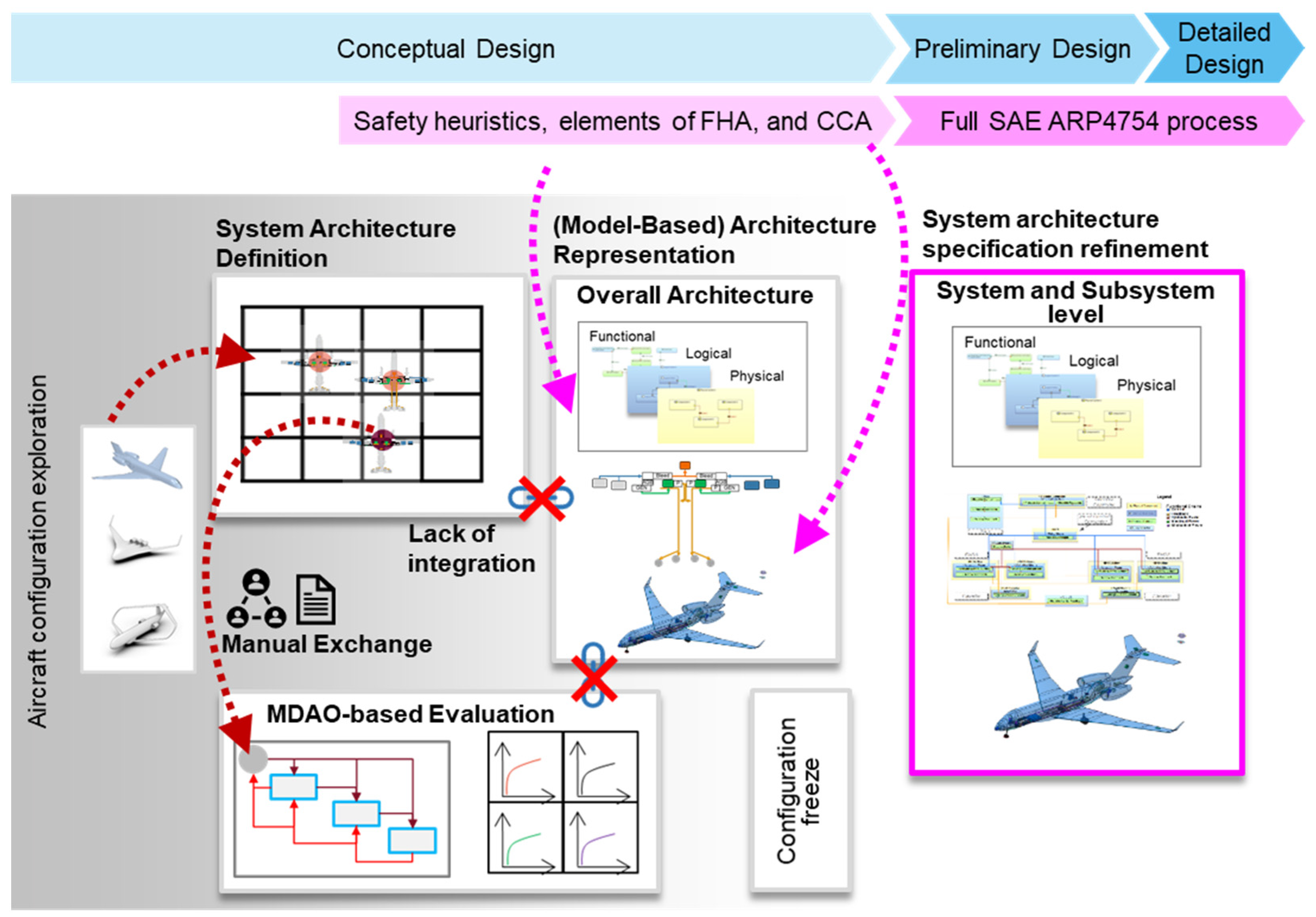
2.6. Summary and Gap Analysis

The literature shows that the aircraft systems architecting process is transitioning towards an increasingly model-based process. Elements of safety assessment such as FHA, FMEA and FTA generation, as well as particular risk assessment (PRA), have been investigated by many researchers at different steps of the architecting process, particularly in architecture evaluation. Several MBSA techniques and tools are available for aircraft system safety assessment. However, these tools must be integrated into a system architecting methodology to be effective. Furthermore, the ideal lifecycle of a system model includes its continuous enrichment from conceptual design to detailed design.
Overall, there is a need for further integration, both amongst the activities in system architecting as well as the integration of safety assessment across the entire range of system architecting activities, i.e., system architecture definition, system architecture representation, and system architecture evaluation.
A gap exists in applying safety assessment to reduce a large design space of system architectures directly, thus enabling a more detailed investigation of system safety within a model-based systems engineering environment and for automation within MDAO frameworks. The latter is particularly important to analyze the feasibility of novel aircraft with hybrid-electric and distributed propulsion architectures. Finally, there is a need to address synergies between existing MBSA techniques and conceptual safety assessment methods in a manner that allows existing tools to be applied right after conceptual systems architecting.

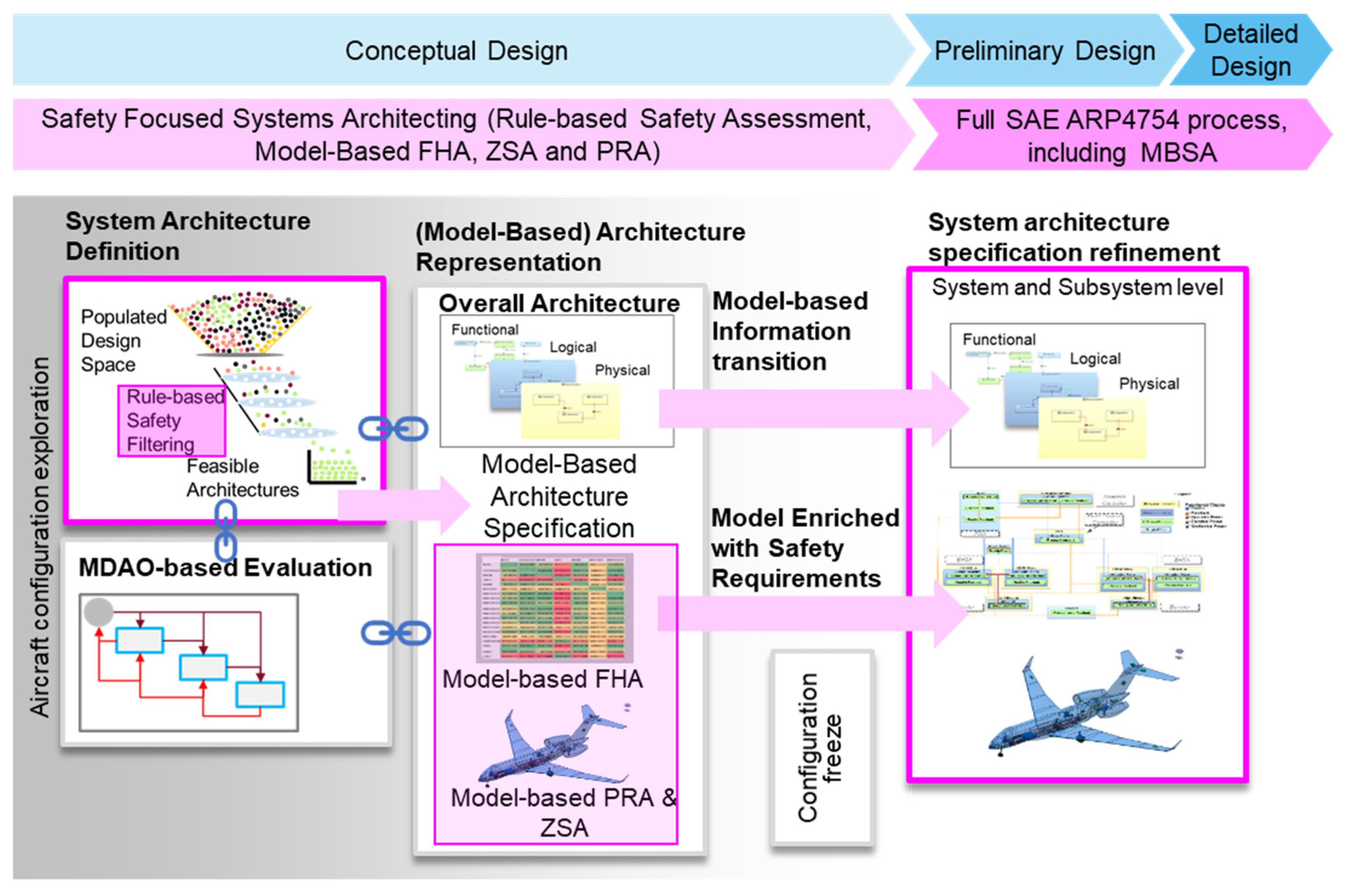
3. Methodology: A Framework for Safety-Focused Systems Architecting

To address the gaps identified in the literature review, the authors propose a safety-focused system architecting framework, shown in Figure 2. The framework features the following enhanced aspects compared to the state of the art:
  • Enhance the system architecture definition phase by introducing a rule-based safety filtering method for conventional and novel system architectures (i.e., for more electric, hybrid-electric, and distributed electric aircraft). This method allows the extraction of feasible architectures from a large design space automatically.
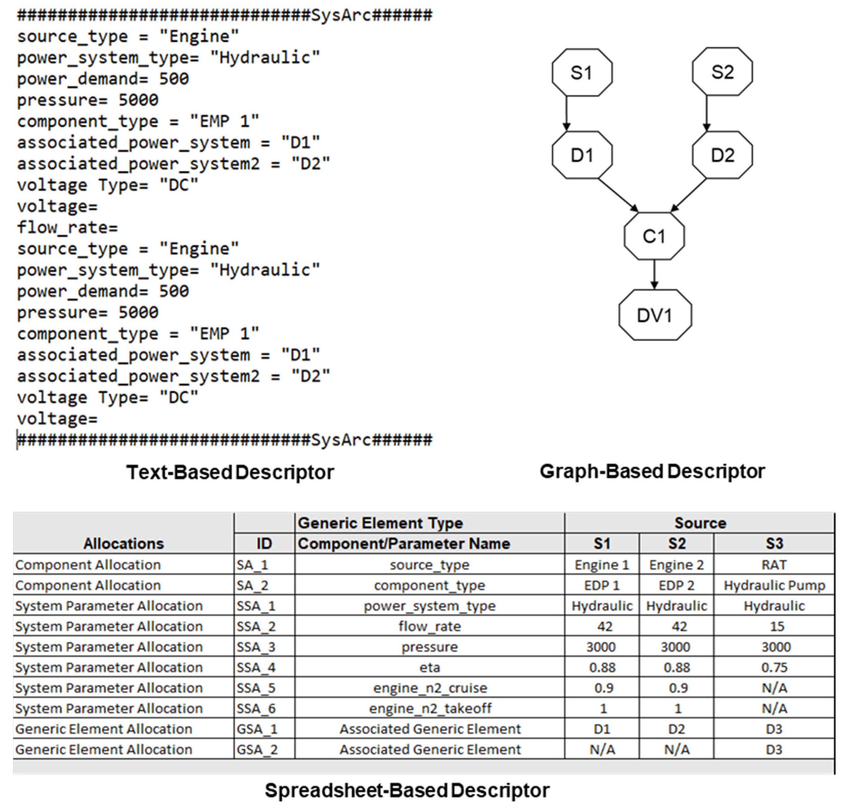
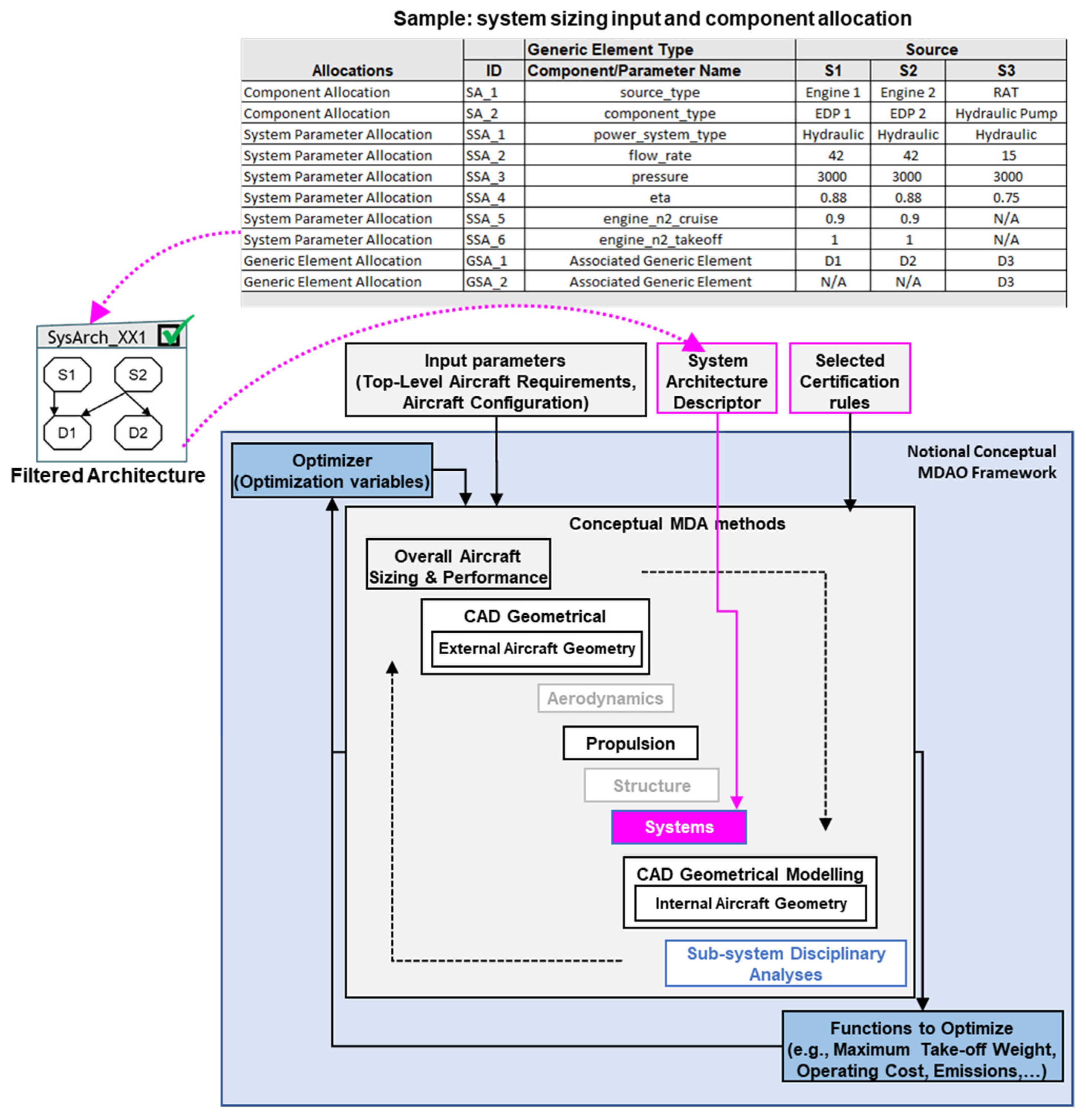
  • Establish links between the system architecture definition, the system architecture representation, and the system architecture evaluation. This specification of the links allows implementation in industry and academic environments using the principle of a system architecture descriptor, which in particular, is the missing link to executable MDAO workflows.
  • Enhance the system architecture representation in an MBSE environment to ease capturing safety requirements in the system architecture earlier in the development, i.e., through linking aspects of the FHA.
The integration links shown in Figure 2 connect each aspect of system architecting together. Each stage of the architecting process typically deals with different means of storing information. The authors propose to use a graph-based system architecture descriptor to transport the system architecture information within the process.
A graph is described as a pairwise relationship between two elements [73]. A collection of element pairs can be used to describe the interrelationships between components in a system. When used for system architecture description, graphs offer a dynamic representation of the architecture and a multi-level repository for storing architectural information. At the abstract level, a graph can be used to describe relationships between components and capture flows of power, energy, and control within a system architecture. A graph-based descriptor also stores information pertinent to system architecture elements within its nodes and interconnections. Graph elements and interconnections can be queried and evaluated, which makes it suitable for testing safety rules. Staack has presented the use of graph-based model representations to support knowledge-based simulation model development within a conceptual product development framework [74]. Graph-based descriptors have also been used in other disciplines, such as in cheminformatics, to encode basic chemical information [75].
Each node in the graph stores information pertinent to system sizing and performance workflows as well as relevant safety parameters. Elements of the generic descriptor can also contain information about which physical components are allotted to them. The descriptor is also linked to a catalog of elements within a Model-Based System Engineering environment (in this case ARCADIA Capella [76]) that is used to instantiate an architecture.
Therefore, by establishing a graph-based architecture descriptor to capture the system architecture input within the framework, the information from diverse sources can be contained within a single entity-which is a key enabler for the integration of the framework’s constituent elements. The graph descriptor can be interfaced with legacy descriptors, such as text-based descriptors that are integrated into MDAO environments or process integration frameworks using custom scripts. More recent information schema, such as CPACS [20] and descriptors based on information stored in other formats, can also be interfaced with graph-based descriptors in a similar manner. Finally, the generic element descriptor is extendable to any type of system architecture that features flows of control, power, or energy. The integration of the graph-based descriptor with architecture evaluation in an MDAO environment is discussed in Section 4.
The following subsection describes these three aspects in more detail and provides examples of their implementation as part of the collaborative research project AGILE4.0 and MDAO-NextGen. Additionally, to prepare the formal safety process of the SAE ARP-4761, the authors propose a mapping of the typical safety analyses into the various aspects of the framework, which is discussed in the following section, implemented into the so-called ASSESS methodology and toolset (ASSESS is an acronym for Aircraft System Safety Assessment).

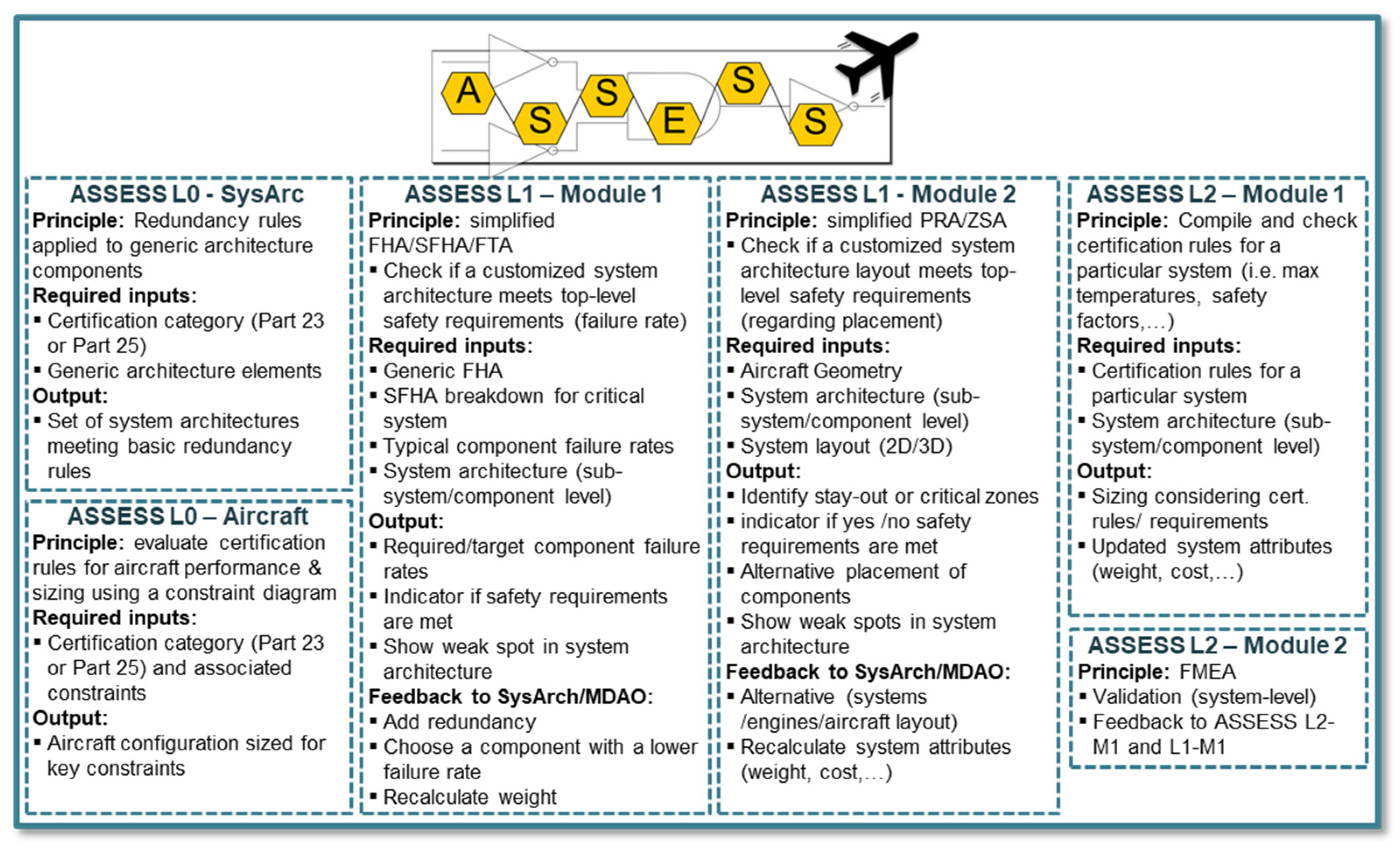
3.1. ASSESS: A Practical Implementation of Safety-Focused Systems Architecting Framework

The Aircraft Systems Lab at Concordia University has implemented the framework as a series of modules, as depicted in Figure 3.
Each module implements a specific aspect of the safety assessment process that is integrated into systems architecting and addresses safety at an increasing level of system architecture granularity. The granularity of each module is expressed using the denotation L0, L1, and L2, with L0 being the lowest and L2 being the most detailed level of granularity, following the principles for multi-fidelity approaches in conceptual design, as established by Piperni et al. [77] and further developed for system-level analyses by Sanchez et al. [78]. Here, L0 methods of the safety assessment are purely suitable for the conceptual design exploration. However, L1 and L2 methods prepare for the formal safety evaluation in terms of the SAE ARP-4761.
The modules of ASSESS also address the abovementioned research gaps. The ASSESS L0 module implements the rule-based safety assessment whereas ASSESS L1-M1, L1-M2, L2-M1, and L2-M2, help capture the system architecture in an MBSE environment and enable safety analyses such as FHA, PRA, Zonal Safety Assessment (ZSA) and Failure Mode and Effects Analysis (FMEA).
L0 analyses at the aircraft and system levels allow for early checks with a low level of granularity. This enables the traversal of large design spaces, thereby ensuring that L1 analyses can focus on a limited set of system architectures. The emerging safety properties (such as required redundancy or segregation) of the system architecture are addressed with L1 methods. These also focus on utilizing information from the aircraft level, such as the external and internal geometry of the aircraft and the placement of system architecture components. L2 methods are applied when a single architecture (or a very limited set) remains and can be analyzed in detail to identify additional safety requirements. Downstream safety tools are then used to perform detailed safety analyses using the system model as the primary artifact.
The various modules of ASSESS are either individual tools or extensions to existing tools. The following Section 3.2, Section 3.3, Section 3.4, Section 3.5 and Section 3.6, provide more details about the individual modules.

3.2. ASSESS L0 Module: Aircraft Level

ASSESS L0-Aircraft is an aircraft-level module that estimates the fuel burn, Maximum Take-Off Weight (MTOW), component weights, and performance of an aircraft from a set of top-level aircraft parameters. Aircraft sizing is subject to performance constraints that are applied according to certification regulations obtained from the airworthiness standards for normal and transport category aircraft such as 14 CFR Part 23 and Part 23 Commuter, and Part 25, respectively [79,80], depending on the category of aircraft. This module implements typical sizing methods from [2,3] that apply to conventional as well as hybrid and all-electric aircraft. This module provides aircraft-level information such as weights, drag, and power demands to system architecture evaluation tools and also uses the weight and drag penalties from the architecture evaluation to determine the impact at the aircraft level.

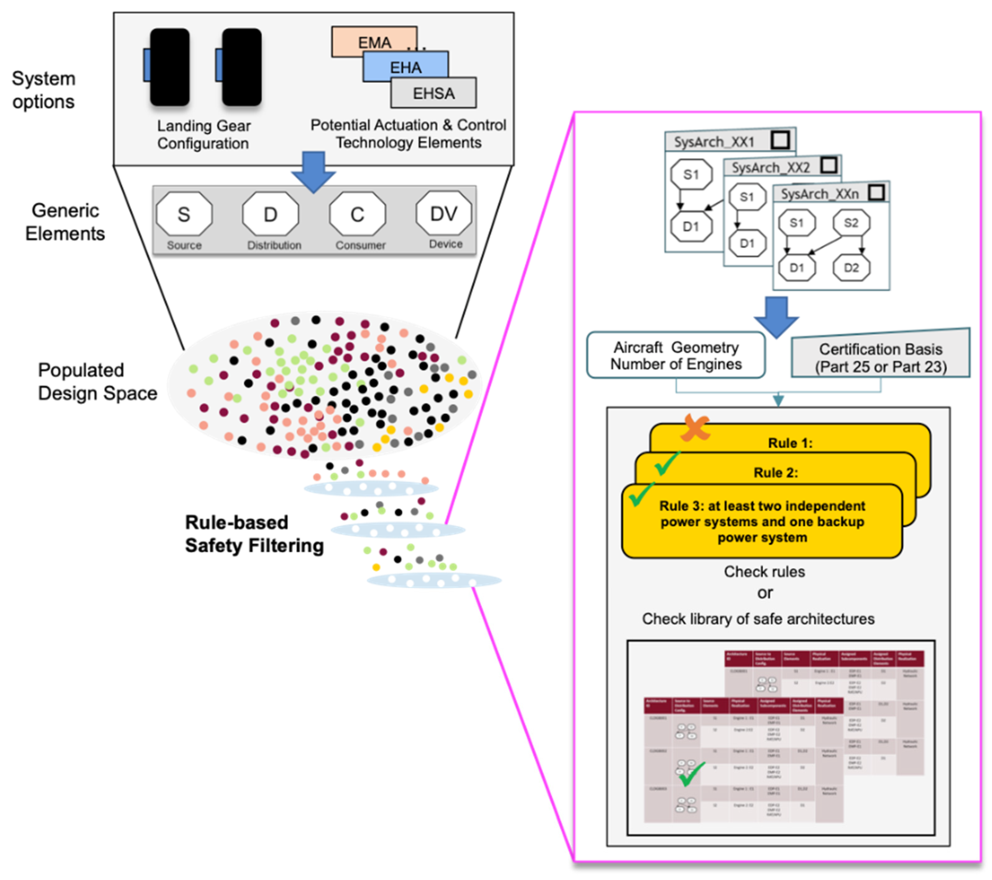
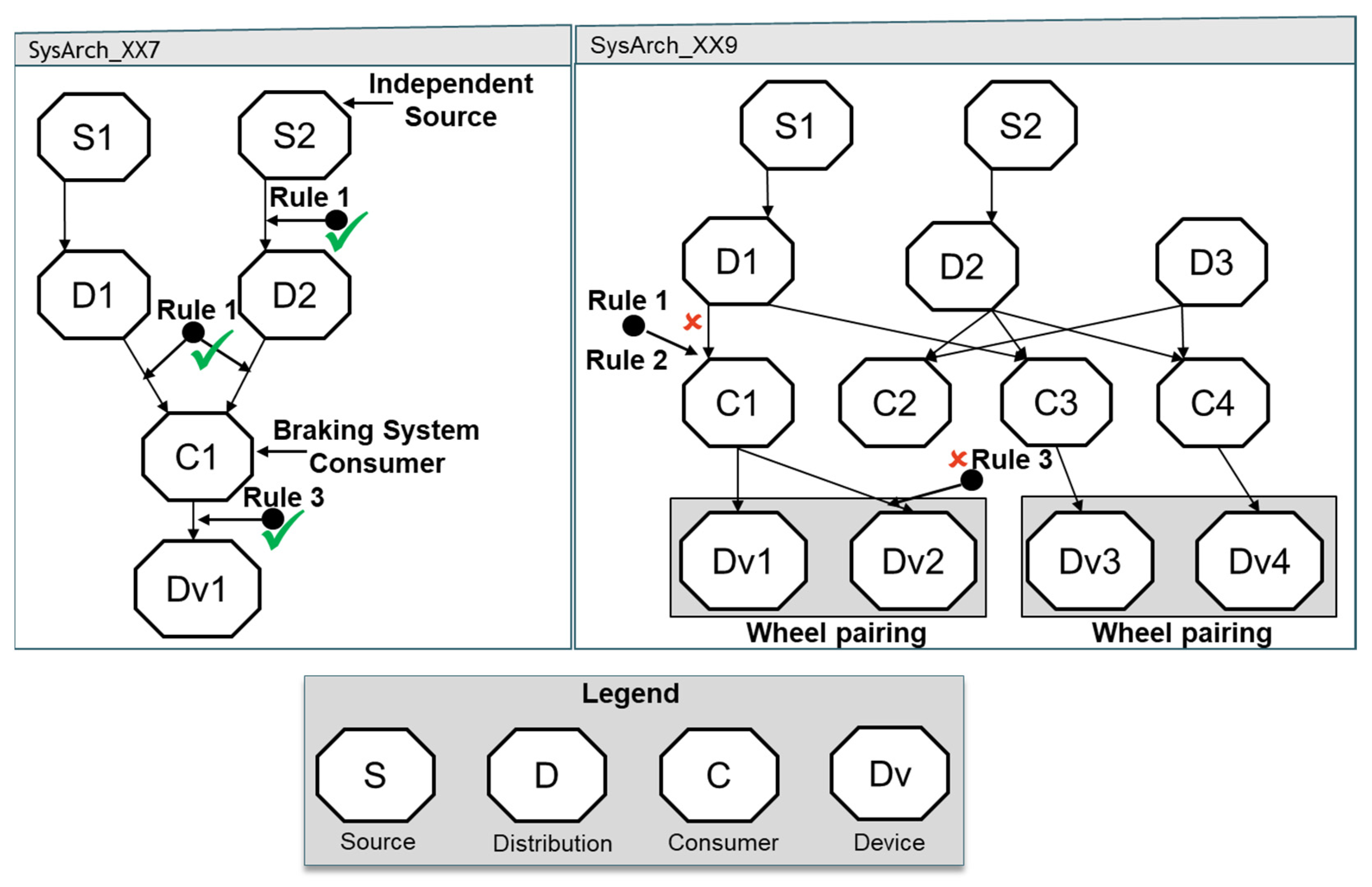
3.3. ASSESS L0 SysArc: Rule-Based Safety Assessment

The ASSESS L0 SysArc module implements a rule-based safety assessment methodology [16] developed by the authors that enables a large design space of aircraft system architectures to be evaluated for safety. It addresses the need to incorporate safety assessment within conceptual design by testing a large design space of candidate architectures against predefined safety rules or heuristics. Rule-based safety assessment is based on the assumption that the traditional aircraft safety assessment process, according to the SAE ARP-4761, is probabilistic and tends the architecture towards greater redundancy [81]. This effect is evident in certified system architectures through the outcome of safety analyses such as the Aircraft Functional Hazard Assessment (AFHA) and System Functional Hazard Assessment (SFHA), which capture potential functional failures that are then mitigated by expert knowledge. The safety rules codify and genericize the outcome of the ARP4761 safety assessment process for existing system architectures and enable the qualitative evaluation of the safety of candidate system architectures in a design space.
The safety rules are synthesized from the following sources:
  • Inherent safety characteristics (redundancy and logic of connections between elements) of certified aircraft system architectures derived from an analysis of 30 aircraft (aircraft certified to Part 23 and Part 25 were analyzed individually)
  • Information extracted from certification regulations, in comparison with existing system architectures
  • Industry best practices derived from reviews with safety analysts and subject matter experts

3.3.1. System Architecture Representation Using Generic Elements

In order to test the safety rules, the system architectures must be represented using a suitable means. The authors introduce a set of generic elements termed: source, distribution, consumer, and device. These enable the system architecture to be abstracted to capture the key flows of energy, power, and signals. Such aspects constitute variability in aircraft system architecture and are important characteristics that inform safety. A mapping of the generic elements to terminology found in literature and typical system components is described by Jeyaraj et al. in [16].

3.3.2. Rule Evaluation and Safety-Based Filtering

The safety rules are evaluated by checking if elements in the generic descriptor comply with the minimum required redundancy in the allocation of power distribution elements, the independence of each distribution element, and the proper allocation of distribution elements to consumers. These checks are implemented by evaluating the incoming and outgoing links between each element based on the requirements of the specific rule that is being tested.
A large design space of system architectures can be filtered using generative and evaluative filtering. In generative filtering, the design space is built by applying the rules to constrain potential combinations resulting in a smaller initial set of architectures. Evaluative filtering first allows an exhaustive population of the design space, followed by the safety-based filtering of the architectures.
Each rule is evaluated using a script to check the connections between the generic elements. A hierarchal approach is followed, starting with the links between device and consumer elements, progressing to the connections between consumer and distribution elements, and finally, the distribution and source elements. The algorithm for checking each connection depends entirely on the rulebase, which can be expanded to accommodate additional rules and aircraft systems. Evaluating rulebases for multiple systems concurrently can introduce additional complexity. Additionally, identifying safety rules for systems featuring multiple types of exchanges (power, data, etc.) between constituent components can be challenging to address. In this paper, the authors have considered a case that deals with power allocation and ensuring sufficient redundancies. However, the framework is also broadly applicable to the abovementioned complex cases.

3.4. ASSESS L1 Module 1-Functional Hazard Assessment within an MBSE Framework

L1-M1 is a methodology that can be implemented in a typical Model-Based Systems Engineering environment and, in this case, uses the Capella tool [82]. It also builds on a modeling framework developed by the authors in [14,64]. The model-based functional hazard assessment seeks to identify emerging safety requirements from the system’s functional and logical architecture. The FHA implemented within an MBSE framework combines the system modeling process with the FHA process. This includes an integration of key steps in the FHA, such as functional analysis and the synthesis of a functional architecture into the system architecture modeling process. A benefit of performing the modeling and FHA simultaneously is that the safety requirements elicited from the FHA can be used to enrich the model in situ. The system model, enriched with safety information, then serves as a basis for downstream analysis using MBSA tools that generate artifacts such as fault trees and reliability block diagrams. This process comprises of system architecture specification and failure identification and tracing. These are described as follows:

3.4.1. System Architecture Specification and Modelling

The methodology applied in this module is tool agnostic. However, the ARCADIA methodology and the Capella tool are selected for use in the author’s specific implementation. The system architecture may be modeled in two ways. The first is a conceptual-level modeling approach relying on a set of generic functions and a catalog of predefined modeling elements developed by the authors [14,64]. Here, the functions, logical and physical components may be initialized based on the system of interest from an existing catalog of elements. The second approach is to define system functions and build logical and physical architectures from the ground up. Both approaches feed into the development of the FHA.

3.4.2. Failure Identification and Tracing

Once the system architecture has been modeled, a set of diagrams within Capella are developed to highlight the hierarchy and interaction of functions. The hierarchy diagrams are first applied to delineate which functions are at the aircraft level and which are at the system level. It can also be used to develop child–parent relationships between functions. The next step is to trace the impact of functional failures using functional chains to highlight the interaction between system functions. This is performed at both the aircraft and system levels.
The analyst then can use the model to examine the impact of known functional failures in a cause-and-effect analysis. The cause and effect analysis traces the impact of a specific functional failure at the aircraft, system, and trans-aircraft and system levels. Following this, a cascading failure analysis can be performed to identify any transverse effect on other aircraft or system-level functions due to a specific functional failure.

3.4.3. Failure Impact and Function Classification

Finally, at this stage, the analyst can evaluate the impact of a system-level failure at the aircraft level and determine the appropriate classification. This classification is applied as a property to the function and color-coded according to the severity. This color code is visible when the functions are allocated to logical and physical architectures, and the corresponding safety targets are also applied to the logical and physical components. At the end of this step, the system model at the logical level is enriched with safety targets, and at the physical level, characteristic component failure rates can be allocated to different physical components. Downstream FTAs can be used to quantitatively determine if the system architecture requires additional redundancies to meet safety targets.

3.5. ASSESS L1 Module 2: System Placement, Particular Risk Assessment, and Zonal Safety Assessment

ASSESS-L1-M2 is a tool that is developed using an open-source geometrical modeler. This module deals with system placement and the safety considerations arising from a Zonal Safety Assessment and Particular Risk Assessment. The overall aircraft geometry, system architecture, and system placement are required to create a 3D model that includes the installation of system components within the aircraft. Here, specific aircraft zones are created, and the assignment of system components to these particular zones is evaluated. Specific analyses such as rotor-burst and tire-burst are carried out by generating regions of exclusion and analyzing if critical components lie within those regions. The output of this module will result in the potential reconfiguration of the architecture and placement of system components.

3.6. ASSESS L2 Module 1: System-Level Certification Rules

ASSESS L2-M1 is integrated with the architecture evaluation techniques that perform a physics-based integrated (aircraft and system level) system sizing and performance estimation. Here, the certification rules pertinent to the sizing of each system are integrated into the sizing tools and directly influence the system mass. Architecture-based fuel system sizing and weight estimation methods developed by Rodriguez et al. [83] and the system sizing methods developed by the Aircraft Systems Lab at Concordia University are also implemented in this module. Another aspect that is considered is that associated with the thermal management of system architectures. The techniques developed by Sanchez et al. [84,85] are applied to determine a thermal risk score of system components, subject to temperature limits for equipment that are derived from certification regulations.

4. Implementation and Discussion

This section discusses the implementation of the architecture definition and rule-based safety assessment of the safety-focused system architecting framework. The selected test case is a landing gear braking system, as this is an example used in the SAE ARP-4761.
For this subsystem, the variability in the design space is characterized by the choice of actuation technology (hydraulic, electric, or both), the associated allocation of power distribution systems to actuation systems, and the allocation of power generation to power distribution systems. These choices result in a large design space of system architectures (approximately 10,000 based on the number of actuator technology variants and the number of ways power systems and power sources can be allocated), as illustrated in Figure 4.
Each architecture is automatically generated and represented using a graph-based descriptor implemented with the NetworkX [86] Python library and is passed to the rule-based safety assessment module (L0 SysArc). Here, the safety rules are evaluated by testing if the system architecture described by the graph descriptor contains links—between each generic element—that comply with the system’s safety rules. The authors implemented two categories of safety rules according to the certification basis (14 CFR Part 23 or 14 CFR Part 25).
The following is an example of a set of rules (based on 14 CFR Part 25) used to filter through a design space of landing gear braking system architectures.
Rule 1—Number of independent power supply sources: This rule ensures that at least two main hydraulic systems supply each hydraulic braking consumer. The backup system could also derive from an independent power source or be supplied locally (using an accumulator or human-powered supply). For aircraft to be certified under Part 25, each braking consumer device must be supplied with at least two independent hydraulic sources and one backup source.
Rule 2—Symmetry in power allocation: The power supply must be allocated symmetrically to prevent asymmetric braking in case of power loss. This rule focuses on preventing asymmetrical braking due to the loss of specific power systems-this is a case typically identified during the Aircraft Level Functional Hazard Assessment (AFHA).
Rule 3—Actuator Allocation: At most one power-consuming braking device is allocated to each wheel. This rule filters unfeasible allocations between the braking device and the wheels for conventional landing gear braking systems.
An example of rule assessment in L0 SysArc is shown in Figure 5. The connections between sources (S1 & S2) and distribution (D1 & D2) in SysArch_00007 ensure that two independent distribution systems always supply the consumer (C1). This is valid because S1 and S2 are independent primary sources. Additionally, C1 is allocated to a unique device, Dv1, and complies with rule three. However, SysArch_00009, in Figure 5, presents a case that fails the checks for compliance with rules 1, 2, and 3. Here, the consumer C1 is only supplied by one independent primary distribution, D1. This violates Rule 2 as C1 is supplied asymmetrically to other braking elements (C2–C4). Finally, C1 is allocated to both Dv1 and Dv2, which is a violation of Rule 3. Another approach to applying rule-based safety filtering is comparing the architectures in the design space to those built using a generative filtering approach. More details on this example, including the link to a function-based design space definition tool, are detailed in another publication by the authors [16].
The architectures that meet the safety rules are then provided to the architecture evaluation module to determine weight and performance metrics. This requires that information required by the evaluation tools is contained within the descriptor. The descriptor can be enriched with this information, during design space generation or after the filtering process. Practical enrichment of the architecture descriptor can be achieved by reading the system sizing inputs from spreadsheets, text files, or directly from python data structures such as dictionaries and data frames.
In this study, one system architecture was considered in isolation. However, the algorithm needs to support the evaluation of multiple systems concurrently to filter the design space effectively.
MDAO Integration
The proposed safety-focused systems architecting framework was developed with the aim of possible integration within an MDAO environment. The graph-based system architecture descriptor links architecture definition and rule-based safety assessment with architecture evaluation and formal architecture specification in an MBSE environment. To support these aspects, one needs to consider the challenges involved in describing system architectures.
Architecture evaluation implemented within stand-alone scripts in MATLAB or Python benefit from the ability to have the architecture description within the script itself, in addition to importing system architecture descriptions from external files. Text files, as in Figure 6, and Extensible Markup Language (XML schema) such as CPACS can be used to describe architectures and also provide system sizing inputs in an automated manner. However, they do not provide detailed information on the links between system components.
Configurational checks, such as prescribing a minimum number of system architecture components, can be applied, but describing component linkages, allocations, and sizing parameters within one file can often be tedious. Furthermore, the evaluation of safety rulebases will have to be inferential, i.e., that different elements of the architecture must be considered to test a safety rule instead of directly checking connections between elements.
Spreadsheet-based wrappers for textual architecture descriptors improve the link between architecture descriptors and system evaluation workflows by providing an understandable interface between the user and the raw text descriptor used by the workflow. Furthermore, this process can also be automated and functions well for conventional system architectures. However, if the conceptual designer wants to evaluate unconventional architectures, then the description schema needs to be changed, and the links between the descriptor elements and the text-based descriptor will have to be manually modified.
The generic-element descriptor addresses the aforementioned challenges by providing a standard nomenclature of terms at a high level of abstraction, which can be extended to any type of energy-based system architecture. Furthermore, the generic elements can encapsulate subcomponent allocations, i.e., specific physical components can be allocated to each of the generic elements. This aspect helps capture information pertinent to the system-level sizing of architecture components.
Finally, since the generic elements are used in a graph-based descriptor, the evaluation of safety rules becomes one of traversing graph nodes based on the type of generic element and testing the applicable rule. The inherent visual properties of a graph make it much easier for a system architect to process than a dense text file or even an excel spreadsheet.
Although the graph-based description is a versatile approach to enabling new capabilities such as safety-based filtering and connection to MDAO and MBSE frameworks, there are still some challenges to the effective implementation of graph-based methods. First is the generation of graph descriptors. The architect must manually create the graphs within a specific environment. In the case of this study, the authors used a Python environment and defined the descriptor using Python dictionaries. A spreadsheet-based initial description was also considered and showed promise as an effective means of integrating system sizing parameters into the MDAO workflow.
The objectives of the system architect and the means of system architecture definition also impact the choice of the descriptor. Suppose the design space is generated using the Architecture Design Space Graph (ADSG) technique of Bussemaker et al. [28,50]. In that case, system sizing parameters may already be assigned to each graph element, and a mapping between ADSG elements and the generic elements in ASSESS can be created. The authors in [16] have shown this aspect.
The generic element descriptor and rule-based safety filtering are directly integrated when the system architecture design space is defined using graphs in a custom environment. The conceptual designer can apply the rule-based safety filters directly to reduce the design space without allocating system sizing parameters, as the safety rules are defined to be generic. One can link the architecture evaluation with the filtered architectures by using a spreadsheet-based approach to allocating subcomponents and providing sizing inputs, as shown in Figure 7. However, some manual intervention is involved if the variability in subcomponents is also considered.

5. Conclusions and Future Work

This paper reviews the current state of safety assessment methods for systems architecting in conceptual design and proposes a safety-focused system architecting framework. This framework applies elements of the SAE ARP461 safety assessment process to each stage of systems architecting and is implemented as a series of modules addressing particular aspects of the safety assessment process requiring increasingly more detail about the system architecture. This paper provides more detail about the first module, L0, which proposes a method to evaluate a large design space of system architectures for safety. This is achieved due to automation using graph-based descriptors. The filtered systems architectures can directly be linked to an architecture evaluation in an MDAO environment. A test case demonstrates the implementation for the landing gear braking system.
The proposed method is deemed to be easily scalable to the complete aircraft system architecture. Furthermore, the extensibility of the generic descriptor enables the integration of safety-based filtering with MDAO evaluation. It also allows potentially any system architecture to be represented and evaluated for safety considerations. However, a hierarchical approach is required to assess rules for multiple systems simultaneously and treat more complex interactions featuring simultaneous exchanges of different types (i.e., power and data).
Future work will demonstrate the scalability at the aircraft level. In addition, the remaining modules, L1 and L2, will be matured and integrated into the ASSESS tool. All modules will cover conventional and novel aircraft system architectures.
In summary, this work integrates safety considerations early in the system architecting process within a model-based systems engineering environment and in doing so, provides a pathway for novel aircraft system architectures to be effectively developed.

Author Contributions

Conceptualization, A.K.J. and S.L.-H.; methodology, A.K.J.; formal analysis, A.K.J.; investigation, A.K.J.; resources, S.L.-H.; writing—original draft preparation, A.K.J.; writing—review and editing, A.K.J. and S.L.-H.; visualization, A.K.J. and S.L.-H.; supervision, S.L.-H.; project administration, S.L.-H.; funding acquisition, S.L.-H. All authors have read and agreed to the published version of the manuscript.

Funding

This research was funded under the Grant Number CRDPJ 538897-19 by the Natural Sciences and Engineering Research Council of Canada (NSERC), the Consortium de recherche et d’innovation en aérospatiale au Québec (CRIAQ), and Bombardier. The presented work also benefited from the authors’ collaboration within the AGILE4.0 project, which receives funding from the European Union’s Horizon 2020 research and innovation program under grant agreement No 815122.

Data Availability Statement

Not applicable here.

Acknowledgments

The authors would like to acknowledge the contributions of Alvaro Tamayo from Bombardier Aerospace for his expert insight through discussions, reviews, and suggestions. The authors would also like to acknowledge Jasper Bussemaker from the DLR for his support in using the ADORE tool to create the architecture design space used in this study.

Conflicts of Interest

The authors declare no conflict of interest. Bombardier contributed to the design of the study, and in the analysis and the decision to publish the results.

References

  1. Pornet, C.; Isikveren, A.T. Conceptual design of hybrid-electric transport aircraft. Prog. Aerosp. Sci. 2015, 79, 114–135. [Google Scholar] [CrossRef]
  2. Finger, D.F.; Braun, C.; Bil, C. An Initial Sizing Methodology for Hybrid-Electric Light Aircraft. In Proceedings of the 2018 Aviation Technology, Integration, and Operations Conference, Atlanta, Georgia, 25–29 June 2018; American Institute of Aeronautics and Astronautics: Reston, VA, USA, 2018. [Google Scholar]
  3. Finger, D.F.; de Vries, R.; Vos, R.; Braun, C.; Bil, C. A Comparison of Hybrid-Electric Aircraft Sizing Methods. In Proceedings of the AIAA Scitech 2020 Forum, Orlando, FL, USA, 6–10 January 2020; AIAA SciTech Forum. American Institute of Aeronautics and Astronautics: Reston, VA, USA, 2020. [Google Scholar]
  4. Sziroczak, D.; Jankovics, I.; Gal, I.; Rohacs, D. Conceptual design of small aircraft with hybrid-electric propulsion systems. Energy 2020, 204, 117937. [Google Scholar] [CrossRef]
  5. Hofmann, J.P.; Stumpf, E.; Weintraub, D.; Köhler, J.; Pham, D.; Schneider, M.; Dickhoff, J.; Burkhart, B.; Reiner, G.; Spiller, M.; et al. A comprehensive approach to the assessment of a hybrid electric powertrain for commuter aircraft. In Proceedings of the AIAA Aviation 2019 Forum, Dallas, TX, USA, 17–21 June 2019; American Institute of Aeronautics and Astronautics Inc., AIAA: Reston, VA, USA, 2019; pp. 1–16. [Google Scholar]
  6. Zamboni, J.; Vos, R.; Emeneth, M.; Schneegans, A. A method for the conceptual design of hybrid electric aircraft. In Proceedings of the AIAA Scitech 2019 Forum, San Diego, CA, USA, 7–11 January 2019. [Google Scholar] [CrossRef] [Green Version]
  7. Selva, D.; Cameron, B.; Crawley, E. System Architecture: Strategy and Product Development for Complex Systems; Pearson: Essex, UK, 2015. [Google Scholar]
  8. Liscouët-Hanke, S.; Maré, J.-C.C.; Pufe, S. Simulation framework for aircraft power system architecting. J. Aircr. 2009, 46, 1375–1380. [Google Scholar] [CrossRef]
  9. Liscouët-Hanke, S. A Model Based Methodology for Integrated Preliminary Sizing and Analysis of Aircraft Power System Architectures. Ph.D. Thesis, Université Toulouse III-Paul Sabatier, Toulouse, France, 2008. [Google Scholar]
  10. Chakraborty, I.; Mavris, D.N. Integrated Assessment of Aircraft and Novel Subsystems Architectures in Early Design. J. Aircr. 2017, 54, 1268–1282. [Google Scholar] [CrossRef]
  11. Boggero, L.; Fioriti, M.; Corpino, S.; Ciampa, P.D. On-board systems preliminary sizing in an overall aircraft design environment. In Proceedings of the 17th AIAA Aviation Technology, Integration, and Operations Conference, Denver, Colorado, 5–9 June 2017; American Institute of Aeronautics and Astronautics Inc., AIAA: Reston, VA, USA, 2017. [Google Scholar]
  12. Tfaily, A.; Liscouet-Hanke, S. Aircraft Systems Physics-Based Weight Estimation Methods for Conceptual Design. In Proceedings of the 76th SAWE International Conference on Mass Properties Engineering, Montreal, QC, Canada, 20–25 May 2017. [Google Scholar]
  13. Maier, M.W.; Rechtin, E. The Art Systems of Architecting; CRC Press: New York, NY, USA, 2009; p. 468. [Google Scholar]
  14. Jeyaraj, A. A Model-Based Systems Engineering Approach for Efficient System Architecture Representation in Conceptual Design: A Case Study for Flight Control Systems. Ph.D. Thesis, Concordia University, Montreal, QC, Canada, 2019. [Google Scholar]
  15. Jeyaraj, A.K.; Tabesh, N.; Liscouët-Hanke, S.; Liscouet-Hanke, S. Connecting Model-based Systems Engineering and Multidisciplinary Design Analysis and Optimization for Aircraft Systems Architecting. In Proceedings of the AIAA AVIATION 2021 FORUM, Virtual, 2–6 August 2021; American Institute of Aeronautics and Astronautics Inc., AIAA: Reston, VA, USA, 2021. Available online: https://arc.aiaa.org/doi/abs/10.2514/6.2021-3077 (accessed on 6 October 2022).
  16. Jeyaraj, A.K.; Bussemaker, J.; Liscouet-Hanke, S.; Boggero, L. Systems Architecting: A Practical Example of Design Space Modeling and Safety-Based Filtering within the AGILE4.0 Project. In Proceedings of the 33rd Congress of the International Council of the Aeronautical Sciences, Stockholm, Sweden, 4–9 September 2022; ICAS: Stockholm, Sweden, 2022. [Google Scholar]
  17. Engineering Process Integration|Noesis Solutions|Noesis Solutions. Available online: https://www.noesissolutions.com/our-products/optimus/engineering-process-integration (accessed on 17 June 2021).
  18. Baughey, K. Functional and Logical Structures: A Systems Engineering Approach; SAE International: Warrendale, PA, USA, 2011. [Google Scholar] [CrossRef]
  19. SAE International. ARP4761:Guidelines and Methods for Conducting the Safety Assessment Process on Civil Airborne Systems and Equipment; SAE International: Warrendale, PA, USA, 1996. [Google Scholar]
  20. DLR CPACS. Available online: https://www.cpacs.de/ (accessed on 4 March 2019).
  21. Alder, M.; Moerland, E.; Jepsen, J.; Nagel, B. Recent Advances in Establishing a Common Language for Aircraft Design with CPACS. In Proceedings of the Aerospace Europe Conference, Bordeaux, Frankreich, 25–28 February 2020. [Google Scholar]
  22. Harish, A.; Gladin, J.; Mavris, D. Framework for design space exploration of novel propulsion system architectures. In Proceedings of the AIAA Scitech 2020 Forum, Orlando, FL, USA, 6–10 January 2020. [Google Scholar] [CrossRef]
  23. AGILE 4.0–Towards Cyber-Physical Collaborative Aircraft Development. Available online: https://www.agile4.eu/ (accessed on 18 June 2021).
  24. Boggero, L.; Ciampa, P.D.; Nagel, B. An MBSE Architectural Framework for the Agile Definition of Complex System Architectures. In Proceedings of the AIAA Aviation 2022 Forum, Chicago, IL, USA, 27 June–1 July 2022. [Google Scholar]
  25. Ciampa, P.D.; Prakasha, P.S.; Torrigiani, F.; Walther, J.-N.; Lefebvre, T.; Bartoli, N.; Timmermans, H.; Della Vecchia, P.; Stingo, L.; Rajpal, D.; et al. Streamlining Cross-Organizational Aircraft Development: Results from the AGILE Project. In Proceedings of the AIAA Aviation 2019 Forum, Dallas, TX, USA, 17–21 June 2019; American Institute of Aeronautics and Astronautics (AIAA): Reston, VA, USA, 2019. [Google Scholar]
  26. Ciampa, P.D.; Nagel, B.; La Rocca, G. A MBSE Approach to MDAO Systems for the Development of Complex Products. In Proceedings of the AIAA Aviation 2020 Forum, Virtual, 15–19 June 2020; American Institute of Aeronautics and Astronautics: Reston, VA, USA, 2020. Available online: https://arc.aiaa.org/doi/10.2514/6.2020-3150 (accessed on 6 October 2022).
  27. Bussemaker, J.H.; Boggero, L.; Ciampa, P.D. From System Architecting to System Design and Optimization: A Link Between MBSE and MDAO. In Proceedings of the INCOSE International Symposium, Detroit, MI, USA, 25–30 June 2022. [Google Scholar]
  28. Bussemaker, J.H.; Ciampa, P.D.; Nagel, B. System architecture design space exploration: An approach to modeling and optimization. In Proceedings of the AIAA Aviation 2020 Forum, Virtual, 15–19 June 2020; American Institute of Aeronautics and Astronautics Inc., AIAA: Reston, VA, USA, 2020; Volume 1, pp. 1–22. Available online: https://www.semanticscholar.org/paper/System-Architecture-Design-Space-Exploration%3A-An-to-Bussemaker-Ciampa/1ef3e89c2c0eb258abd11df440a978d46303c211 (accessed on 6 October 2022).
  29. Bussemaker, J.H.; Ciampa, P.D. MBSE in Architecture Design Space Exploration. Handb. Model. Syst. Eng. 2022, 1–41. [Google Scholar] [CrossRef]
  30. Torrigiani, F.; Ciampa, P.D.; Nagel, B.; Deinert, S.; Fioriti, M.; Di Fede, F.; Pisu, L.; Gatti, S.; Sanchez, F.; Liscouët-Hanke, S.; et al. MBSE Certification-Driven Design of a UAV MALE Configuration in the AGILE 4.0 Design Environment. In Proceedings of the AIAA AVIATION 2021 FORUM, Virtual, 2–6 August 2021; Available online: https://www.zenodo.org/record/5735365#.Y4nAxfdBxPY (accessed on 6 October 2022). [CrossRef]
  31. Cabaleiro, C.; Fioriti, M.; Boggero, L. Methodology for the Automated Preliminary Certification of On-Board Systems Architectures through Requirements Analysis. In Proceedings of the 33rd Congress of the International Council of the Aeronautical Sciences, Stockholm, Sweden, 4–9 September 2022; ICAS: Stockholm, Sweden, 2022. [Google Scholar]
  32. Fioriti, M.; Cabaleiro, C.; Lefebvre, T.; Della Vecchia, P.; Mandorino, M.; Liscouët-Hanke, S.; Jeyaraj, A.; Donelli, G.; Jungo, A. Multidisciplinary Design of a More Electric Regional Aircraft Including Certification Constraints. In Proceedings of the AIAA AVIATION 2022 Forum, Chicago, IL, USA, 27 June–1 July 2022. [Google Scholar] [CrossRef]
  33. Bornholdt, R.; Kreitz, T.; Thielecke, F. Function-Driven Design and Evaluation of Innovative Flight Controls and Power System Architectures; SAE Technical Papers: Warrendale, PA, USA, 2015. [Google Scholar]
  34. Bornholdt, R. Systemübergreifende Analyse und Bewertung von Architekturvarianten Neuartiger Flugzeugsysteme Anhand von Sicherheits-und Betriebsaspekten; Doktorarbeit, Technische Universität Hamburg: Hamburg, Germany, 2021. [Google Scholar]
  35. Jimeno, S.; Molina-Cristobal, A.; Riaz, A.; Guenov, M.D.; Altelarrea, S.J.; Molina-Cristóbal, A.; Riaz, A.; Guenov, M.D. Incorporating Safety in Early (Airframe) Systems Design and Assessment. In Proceedings of the AIAA Scitech Forum, San Diego, CA, USA, 7–11 January 2019; American Institute of Aeronautics and Astronautics Inc.: Reston, VA, USA, 2019. [Google Scholar]
  36. Jimeno, S.; Riaz, A.; Guenov, M.D.; Molina-Cristobal, A. Enabling Interactive Safety and Performance Trade-Offs in Early Airframe Systems Design. In Proceedings of the AIAA Scitech Forum, Orlando, FL, USA, 6–10 January 2020; American Institute of Aeronautics and Astronautics Inc.: Reston, VA, USA, 2020; Volume 1, pp. 1–16. [Google Scholar]
  37. Fusaro, R.; Viola, N.; Ferretto, D.; Fioritti, M.; Boggero, L. Methodology for the Safety and Reliability Assessment of Hypersonic Transportation Systems in Conceptual Design Activities. In Proceedings of the 21st AIAA International Space Planes and Hypersonics Technologies Conference, Xiamen, China, 6–9 March 2017; American Institute of Aeronautics and Astronautics: Xiamen, China, 2017. [Google Scholar]
  38. Chiesa, S.; Corpino, S.; Fioriti, M.; Rougier, A.; Viola, N. Zonal Safety Analysis in Aircraft Conceptual Design: Application to SAvE Aircraft. Proc. Inst. Mech. Eng. Part G J. Aerosp. Eng. 2013, 227, 714–733. [Google Scholar] [CrossRef]
  39. Zwicky, F. Morphological Analysis and Construction; Wiley Inter-Science: New York, NY, USA, 1948. [Google Scholar]
  40. Engler, W.; Biltgen, P.; Mavris, D. Concept Selection Using an Interactive Reconfigurable Matrix of Alternatives (IRMA). In Proceedings of the 45th AIAA Aerospace Sciences Meeting and Exhibit, Reno, Nevada, 8–11 January 2007; Aerospace Sciences Meetings. American Institute of Aeronautics and Astronautics: Reston, VA, USA, 2007. [Google Scholar]
  41. Armstrong, M. A Process for Function Based Architecture—Definition and Modeling. Ph.D. Thesis, Georgia Institute of Technology, Atlanta, GA, USA, 2008. [Google Scholar]
  42. Armstrong, M.; de Tenorio, C.; Mavris, D.; Garcia, E. Function Based Architecture Design Space Definition and Exploration. In Proceedings of the 26th Congress of ICAS and 8th AIAA ATIO, Anchorage, AK, USA, 14–19 September 2008; American Institute of Aeronautics and Astronautics: Reston, VA, USA, 2008. [Google Scholar]
  43. Lammering, T. Integration of Aircraft Systems into Conceptual Design Synthesis. Ph.D. Thesis, RTWH Aachen University, Aachen, Germany, 2014. [Google Scholar]
  44. Zeidner, L.E.; Reeve, H.M.; Khire, R.; Becz, S. Architectural Enumeration & Evaluation for Identification of Low-Complexity Systems. In Proceedings of the 10th AIAA Aviation Technology, Integration and Operations Conference 2010, Fort Worth, TX, USA, 13–15 September 2010; Volume 3. [Google Scholar]
  45. Becz, S.; Pinto, A.; Zeidner, L.E.; Khire, R.; Banaszuk, A.; Reeve, H.M. Design System for Managing Complexity in Aerospace Systems. In Proceedings of the 10th AIAA Aviation Technology, Integration and Operations Conference 2010, Fort Worth, TX, USA, 13–15 September; Volume 2.
  46. Chakraborty, I.; Mavris, D.N. Heuristic Definition, Evaluation, and Impact Decomposition of Aircraft Subsystem Architectures. In Proceedings of the 16th AIAA Aviation Technology, Integration, and Operations Conference, Washington, DC, USA, 13–17 June 2016; American Institute of Aeronautics and Astronautics: Reston, VA, USA, 2016. [Google Scholar]
  47. Garriga, A.G.; Mainini, L.; Ponnusamy, S.S. A Machine Learning Enabled Multi-Fidelity Platform for the Integrated Design of Aircraft Systems. J. Mech. Des. 2019, 141, 121405. [Google Scholar] [CrossRef] [Green Version]
  48. Bauer, C.; Lagadec, K.; Bès, C.; Mongeau, M. Flight Control System Architecture Optimization for Fly-by-Wire Airliners. J. Guid. Control. Dyn. 2007, 30, 1023–1029. [Google Scholar] [CrossRef]
  49. Bussemaker, J.H.; Boggero, L. Technologies for Enabling System Architecture Optimization. In Proceedings of the ODAS Symposium, Hamburg, Germany, 1–3 June 2022. [Google Scholar]
  50. Bussemaker, J.H.; Ciampa, P.D.; Nagel, B. System Architecture Design Space Modeling and Optimization Elements. In Proceedings of the 32nd Congress of the International Council of the Aeronautical Sciences, Shanghai, China, 6–10 September 2021. [Google Scholar]
  51. Raymer, D. Aircraft Design: A Conceptual Approach 5e and RDSWin STUDENT; American Institute of Aeronautics and Astronautics, Inc.: Reston, VA, USA, 2012. [Google Scholar]
  52. Roskam, J. Airplane Design: Part I; Roskam Aviation and Engineering Corp.: Lawrence, Kansas, 2015; ISBN 9781884885426 188488542X. [Google Scholar]
  53. De Tenorio, C. Methods for Collaborative Conceptual Design of Aircraft Power Architectures; Georgia Institute of Technology: Atlanta, GA, USA, 2010. [Google Scholar]
  54. Available online: https://www.researchgate.net/publication/322310336_Integrated_Assessment_of_Vehicle-level_Performance_of_Novel_Aircraft_Concepts_and_Subsystem_Architectures_in_Early_Design (accessed on 6 October 2022).
  55. Bayer, T. Is MBSE Helping? Measuring Value on Europa Clipper. In Proceedings of the 2018 IEEE Aerospace Conference, Big Sky, MT, USA, 3–10 March 2018; pp. 1–13. [Google Scholar]
  56. Bayer, T.J.; Chung, S.; Cole, B.; Cooke, B.; Dekens, F.; Delp, C.; Gontijo, I.; Lewis, K.; Moshir, M.; Rasmussen, R.; et al. Model Based Systems Engineering on the Europa Mission Concept Study. In Proceedings of the 2012 IEEE Aerospace Conference, Big Sky, MT, USA, 3–10 March 2012. [Google Scholar]
  57. Bayer, T.; Chung, S.; Cole, B.; Cooke, B.; Dekens, F.; Delp, C.; Gontijo, I.; Lewis, K.; Moshir, M.; Rasmussen, R.; et al. Early Formulation Model-Centric Engineering on NASA’s Europa Mission Concept Study. INCOSE Int. Symp. 2012, 22, 1695–1710. [Google Scholar] [CrossRef]
  58. Chami, M.; Oggier, P.; Naas, O.; Heinz, M. Real World Application of MBSE at Bombardier Transportation; Swiss Systems Engineering Day, Swiss Society of Systems Engineering: Zurich, Switzerland, 2015. [Google Scholar]
  59. George Mathew, P.; Liscouet-Hanke, S.; Le Masson, Y. Model-Based Systems Engineering Methodology for Implementing Networked Aircraft Control System on Integrated Modular Avionics—Environmental Control System Case Study; SAE Technical Paper: Warrendale, PA, USA, 2018. [Google Scholar] [CrossRef]
  60. Becker, C.; Giese, T. Application of Model Based Functional Specification Methods to Environmental Control Systems Engineering. SAE Int. J. Aerosp. 2011, 4, 637–651. [Google Scholar] [CrossRef]
  61. Fisher, Z.C.; Daniel Cooksey, K.; Mavris, D. A Model-Based Systems Engineering Approach to Design Automation of SUAS. In Proceedings of the 2017 IEEE Aerospace Conference, Big Sky, MT, USA, 4–11 March 2017; pp. 1–15. [Google Scholar]
  62. Liscouët-Hanke, S.; Jahanara, H.; Bauduin, J.L. A Model-Based Systems Engineering Approach for the Efficient Specification of Test Rig Architectures for Flight Control Computers. IEEE Syst. J. 2020, 14, 5441–5450. [Google Scholar] [CrossRef]
  63. Malone, R.; Friedland, B.; Herrold, J.; Fogarty, D. Insights from Large Scale Model Based Systems Engineering at Boeing. INCOSE Int. Symp. 2016, 26, 542–555. [Google Scholar] [CrossRef]
  64. Liscouët-Hanke, S.; Jeyaraj, A. A Model-Based Systems Engineering Approach for Efficient Flight Control System Architecture Variants Modelling in Conceptual Design. In Proceedings of the International Conference on Recent Advances in Aerospace Actuation Systems and Components, Toulouse, France, 30 May–1 June 2018; pp. 34–41. [Google Scholar]
  65. Bleu-Laine, M.-H.; Bendarkar, M.V.; Xie, J.; Briceno, S.I.; Mavris, D.N. A Model-Based System Engineering Approach to Normal Category Airplane Airworthiness Certification. In Proceedings of the AIAA Aviation 2019 Forum, Dallas, TX, USA, 17–21 June 2019. [Google Scholar]
  66. Joshi, A.; Heimdahl, M.P.E.; Miller, S.P.; Whalen, M.W. Model-Based Safety Analysis; NASA: Washington, DC, USA, 2006.
  67. Lisagor, O.; Kelly, T.; Niu, R. Model-Based Safety Assessment: Review of the Discipline and Its Challenges. In Proceedings of the 2011 9th International Conference on Reliability, Maintainability and Safety, Guiyang, China, 12–15 June 2011; pp. 625–632. [Google Scholar]
  68. Gradel, S.; Aigner, B.; Stumpf, E. Model-Based Safety Assessment for Conceptual Aircraft Systems Design. CEAS Aeronaut. J. 2022, 13, 281–294. [Google Scholar] [CrossRef]
  69. Bruno, F.; Fioriti, M.; Donelli, G.; Boggero, L.; Ciampa, P.D.; Nagel, B. A Model-Based RAMS Estimation Methodology for Innovative Aircrafton-Board Systems Supporting MDO Applications. In Proceedings of the AIAA Aviation 2020 Forum, Virtual, 15–19 June 2020; American Institute of Aeronautics and Astronautics: Reston, VA, USA, 2020. Available online: https://arc.aiaa.org/doi/abs/10.2514/6.2020-3151 (accessed on 6 October 2022).
  70. Abdellatif, A.A.; Holzapfel, F. New Methodology for Model-Based Safety Analysis. In Proceedings of the IEEE Aerospace Conference Proceedings, Big Sky, MT, USA, 2–9 March 2019; pp. 1–7. [Google Scholar]
  71. Abdellatif, A.A.; Holzapfel, F. Model Based Safety Analysis (MBSA) Tool for Avionics Systems Evaluation. In Proceedings of the 2020 AIAA/IEEE 39th Digital Avionics Systems Conference (DASC), San Antonio, TX, USA, 11–15 October 2020; pp. 1–5. [Google Scholar]
  72. Boggero, L.; Fioriti, M.; Donelli, G.; Ciampa, P.D. Model-Based Mission Assurance/ModelBased Reliability, Availability, Maintainability, and Safety (RAMS). In Handbook of Model-Based Systems Engineering; Springer: Berlin/Heidelberg, Germany, 2022. [Google Scholar]
  73. Diestel, R. Graph Theory; Springer Nature: Berlin/Heidelberg, Germany, 2017. [Google Scholar]
  74. Staack, I. Aircraft Systems Conceptual Design: An Object-Oriented Approach from Element to Aircraft. Ph.D. Thesis, Linköping University, Linköping, Sweden, 2016. [Google Scholar]
  75. Jiang, D.; Wu, Z.; Hsieh, C.Y.; Chen, G.; Liao, B.; Wang, Z.; Shen, C.; Cao, D.; Wu, J.; Hou, T. Could Graph Neural Networks Learn Better Molecular Representation for Drug Discovery? A Comparison Study of Descriptor-Based and Graph-Based Models. J. Cheminform. 2021, 13, 1–23. [Google Scholar] [CrossRef] [PubMed]
  76. Roques, P. Systems Architecture Modeling with the Arcadia Method: A Practical Guide to Capella; Roques, P., Ed.; Elsevier: Amsterdam, The Netherlands, 2018; pp. 25–50. [Google Scholar]
  77. Piperni, P.; DeBlois, A.; Henderson, R. Development of a Multilevel Multidisciplinary-Optimization Capability for an Industrial Environment. AIAA J. 2013, 51, 2335–2352. [Google Scholar] [CrossRef]
  78. Sanchez, F.; Liscouët-hanke, S.; Tfaily, A. Improving Aircraft Conceptual Design through Parametric CAD Modellers—A Case Study for Thermal Analysis of Aircraft Systems. Comput. Ind. 2021, 130. [Google Scholar] [CrossRef]
  79. ECFR: 14 CFR Part 23—Airworthiness Standards: Normal Category Airplanes. Available online: https://www.ecfr.gov/current/title-14/chapter-I/subchapter-C/part-23 (accessed on 28 May 2022).
  80. 14 CFR Part 25—Airworthiness Standards: Transport Category Airplanes. Available online: https://www.law.cornell.edu/cfr/text/14/part-25 (accessed on 28 May 2022).
  81. Leveson, N.; Wilkinson, C.; Fleming, H.C.; Thomas, J.; Tracy, I. A Comparison of STPA and the ARP 4761 Safety Assessment Process; MIT Technical Report; Massachusetts Institute of Technology: Cambridge, MA, USA, 2014. [Google Scholar]
  82. Capella MBSE Tool—Arcadia. Available online: https://polarsys.org/capella/arcadia.html (accessed on 4 March 2019).
  83. Rodriguez, C.D.; Liscouët-Hanke, S. Architecture-Based Weight Estimation Method for the Conceptual Design of Aircraft Fuel Systems. In Proceedings of the Aiaa Aviation 2021 Forum, Virtual, 2–6 August 2021; Available online: https://arc.aiaa.org/doi/10.2514/6.2021-2408 (accessed on 6 October 2022). [CrossRef]
  84. Sanchez, F.; Liscouët-Hanke, S. Thermal Risk Prediction Methodology for Conceptual Design of Aircraft Equipment Bays. Aerosp. Sci. Technol. 2020, 104, 105946. [Google Scholar] [CrossRef]
  85. Sanchez, F.; Huzaifa, A.M.; Liscouët-Hanke, S. Ventilation Considerations for an Enhanced Thermal Risk Prediction in Aircraft Conceptual Design. Aerosp. Sci. Technol. 2021, 108, 106401. [Google Scholar] [CrossRef]
  86. Hagberg, A.; Swart, P.; Chult, D.S. Exploring Network Structure, Dynamics, and Function Using NetworkX; Los Alamos National Laboratory: Santa Fe, NM, USA, 2008.
Figure 1. Current system architecture design space exploration process.
Aerospace 09 00791 g001
Figure 2. The proposed safety-focused systems architecting framework features enhanced links between the architecting steps and enables earlier safety assessment.
Aerospace 09 00791 g002
Figure 3. Aircraft Systems Safety assessment-(ASSESS) methodology implementing the safety-focused systems architecting framework.
Aerospace 09 00791 g003
Figure 4. Example of rule-based safety assessment for the system architecture definition phase; applied to a design space of landing gear braking system architectures.
Aerospace 09 00791 g004
Figure 5. Rule assessment using generic element descriptor.
Aerospace 09 00791 g005
Figure 6. Various types of architecture descriptors used in architecture evaluation workflows.
Aerospace 09 00791 g006
Figure 7. Applying system sizing inputs to the generic graph-based descriptor.
Aerospace 09 00791 g007
Publisher’s Note: MDPI stays neutral with regard to jurisdictional claims in published maps and institutional affiliations.

