
Design of a Distributedly Active Morphing Wing Based on Digital Metamaterials

 ,
, 
Abstract
:1. Introduction
2. Reversibly Assembled Active Morphing Lattice Structures
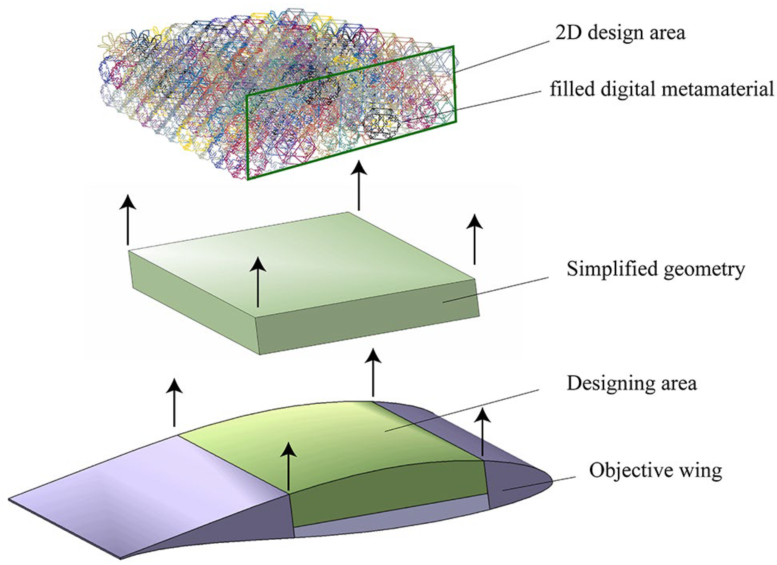
2.1. Building-Block Concept
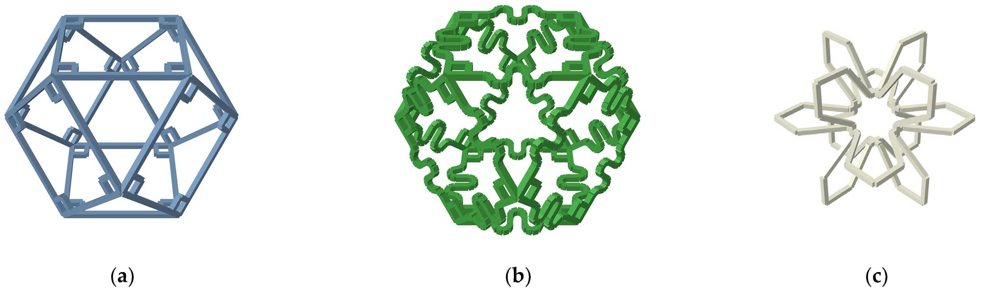
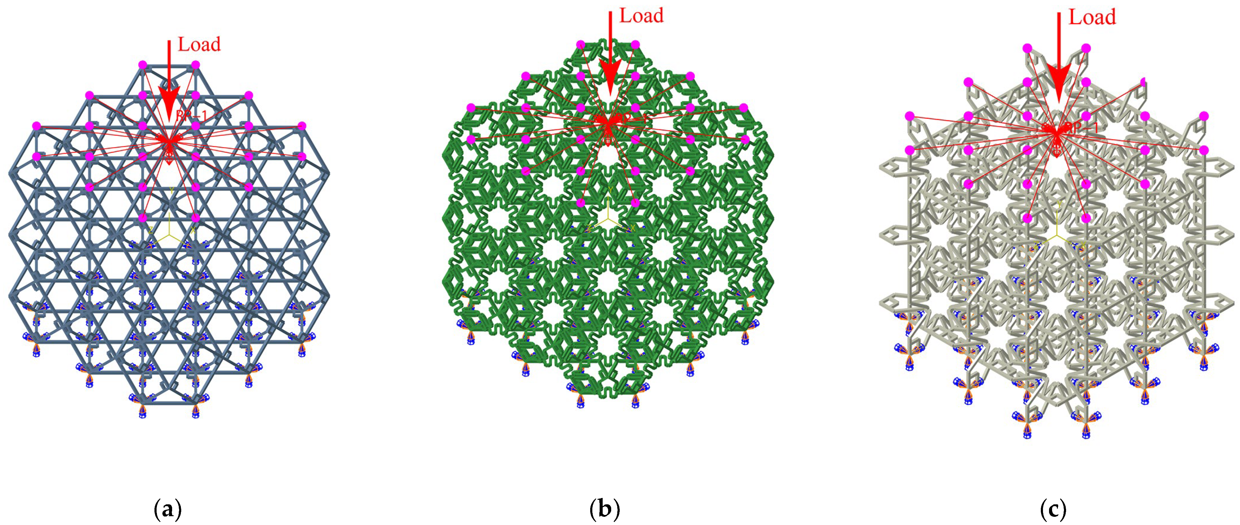
2.2. Fundamental Cells
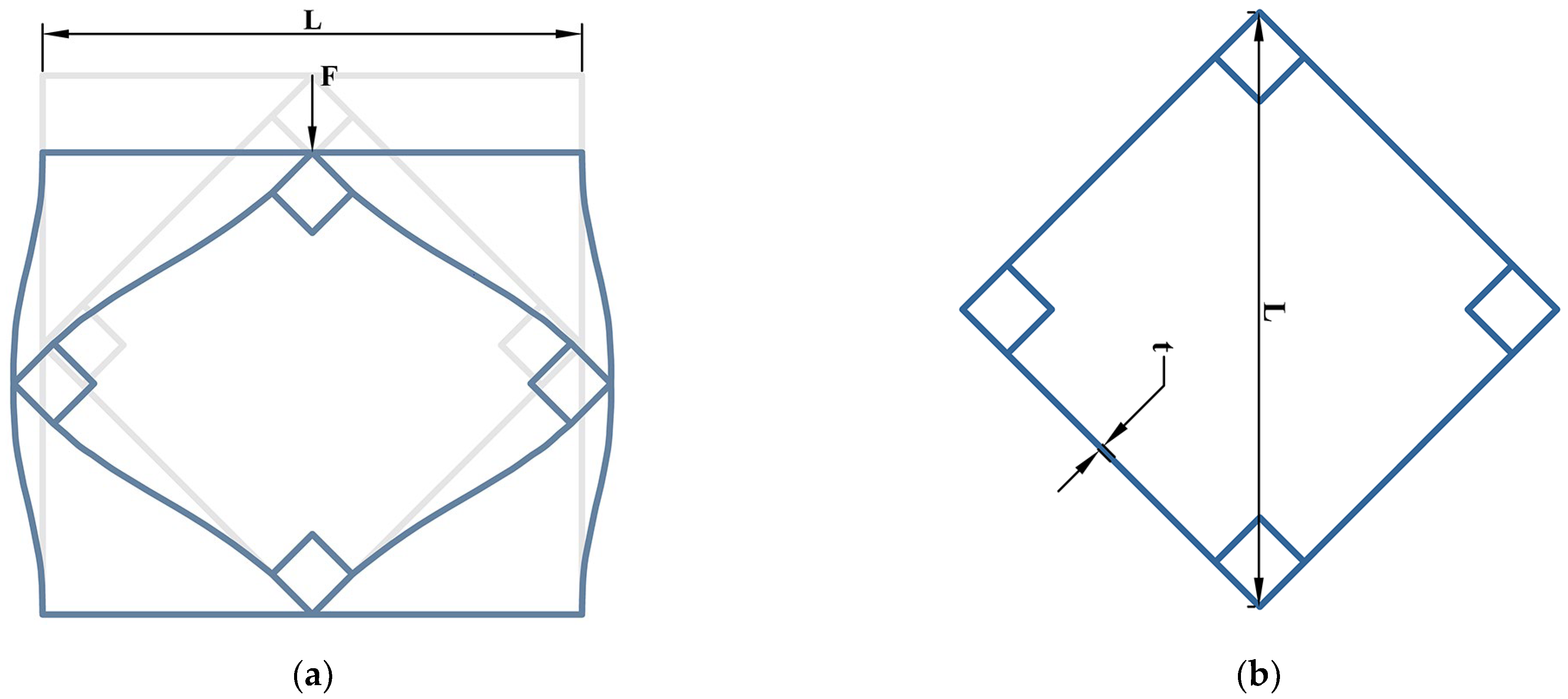
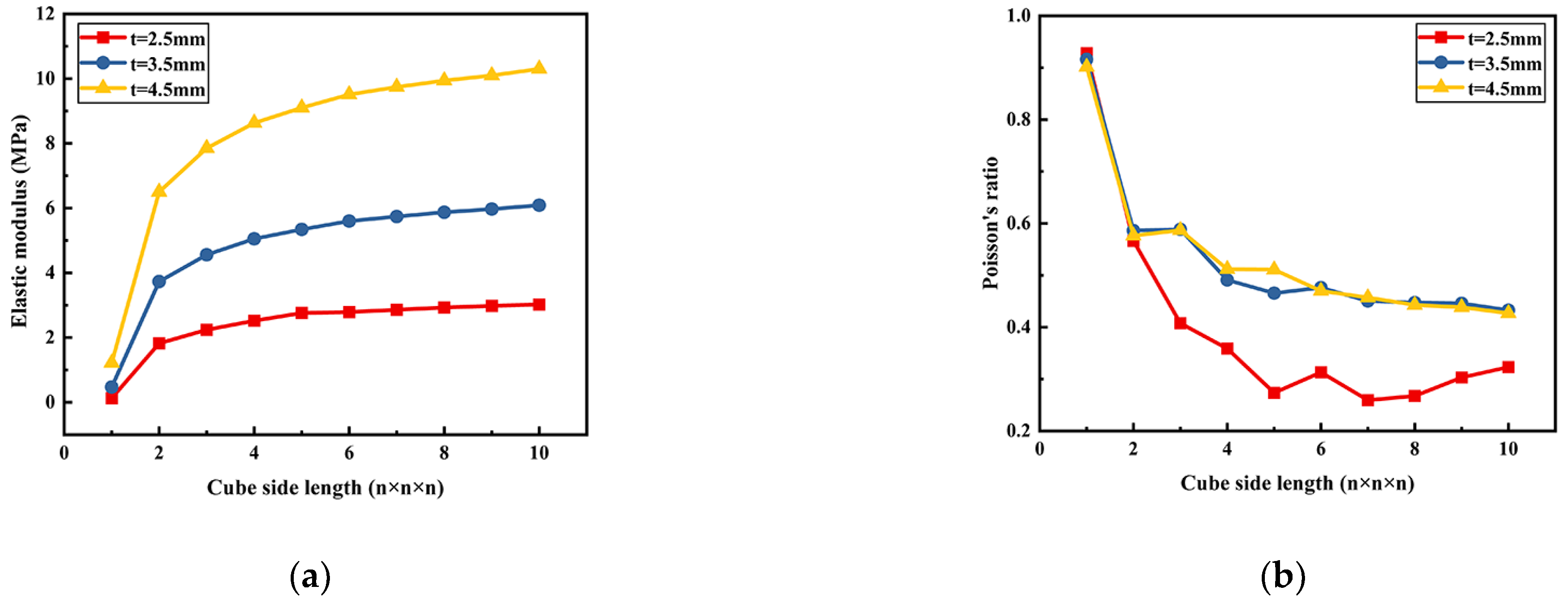
2.2.1. Rigid Cell
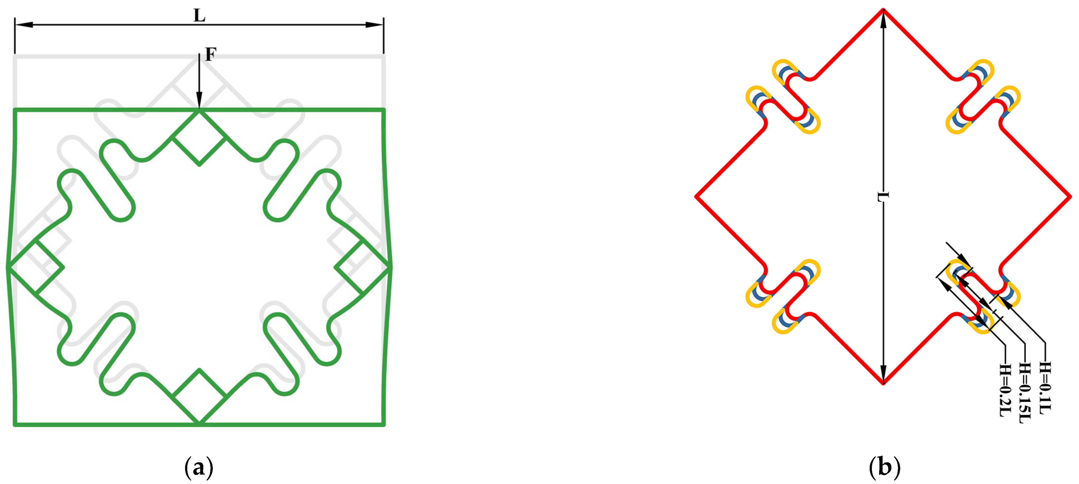
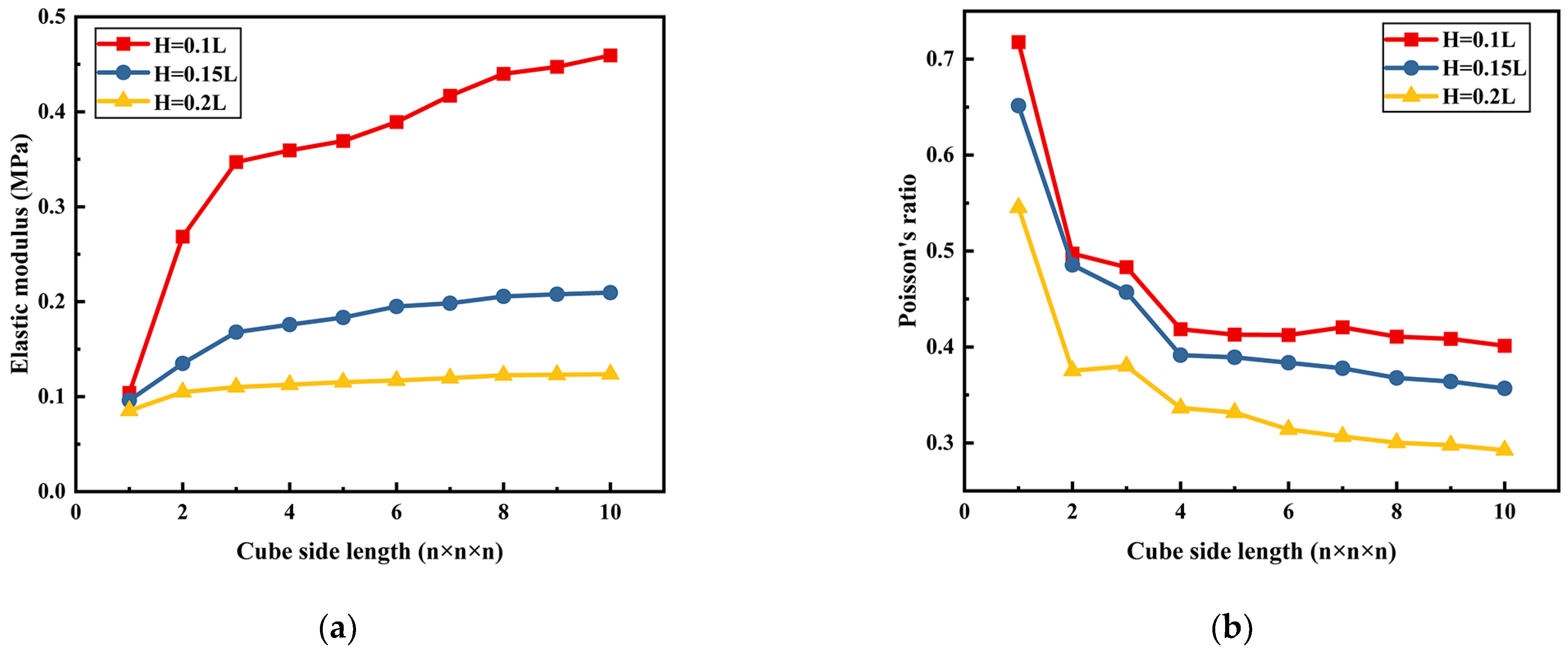
2.2.2. Compliant Cell
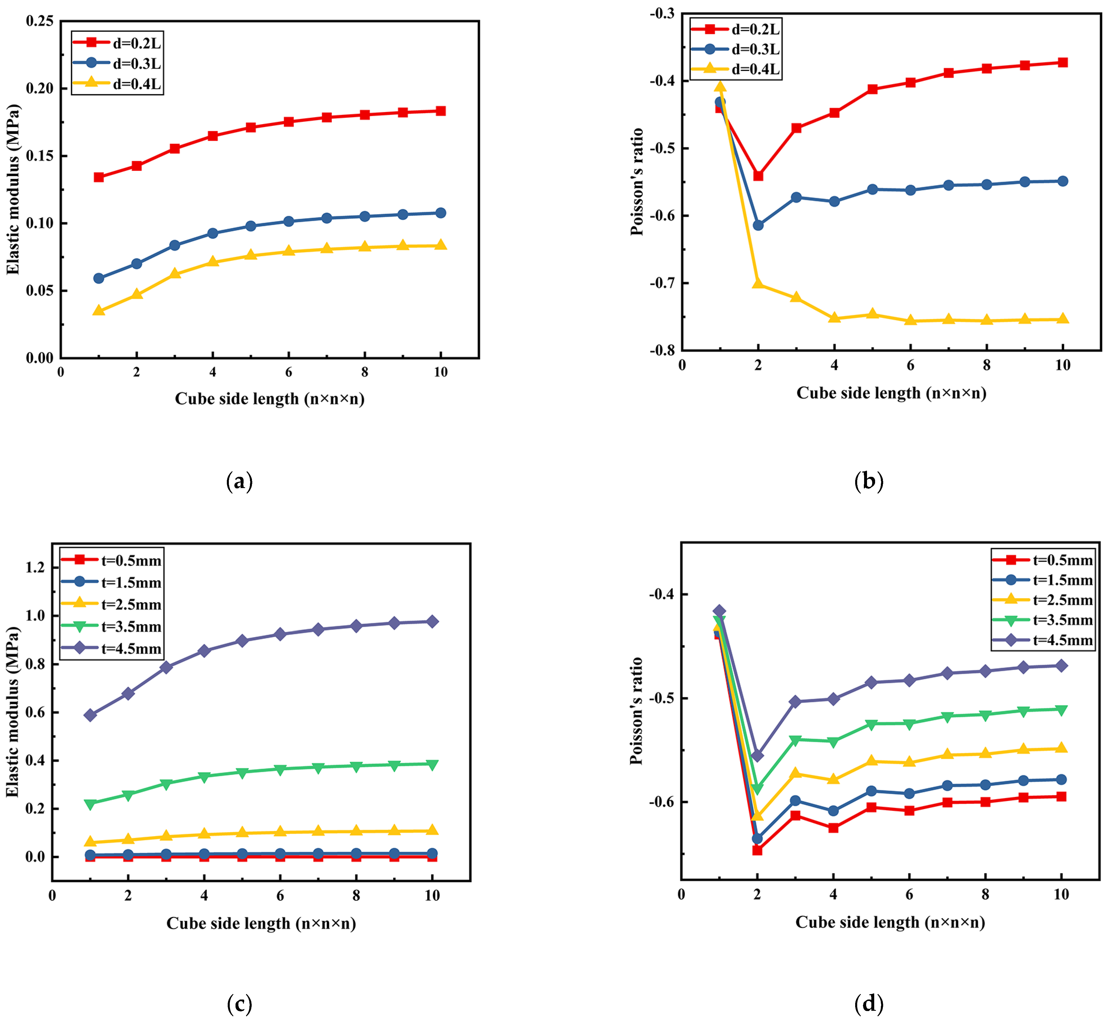
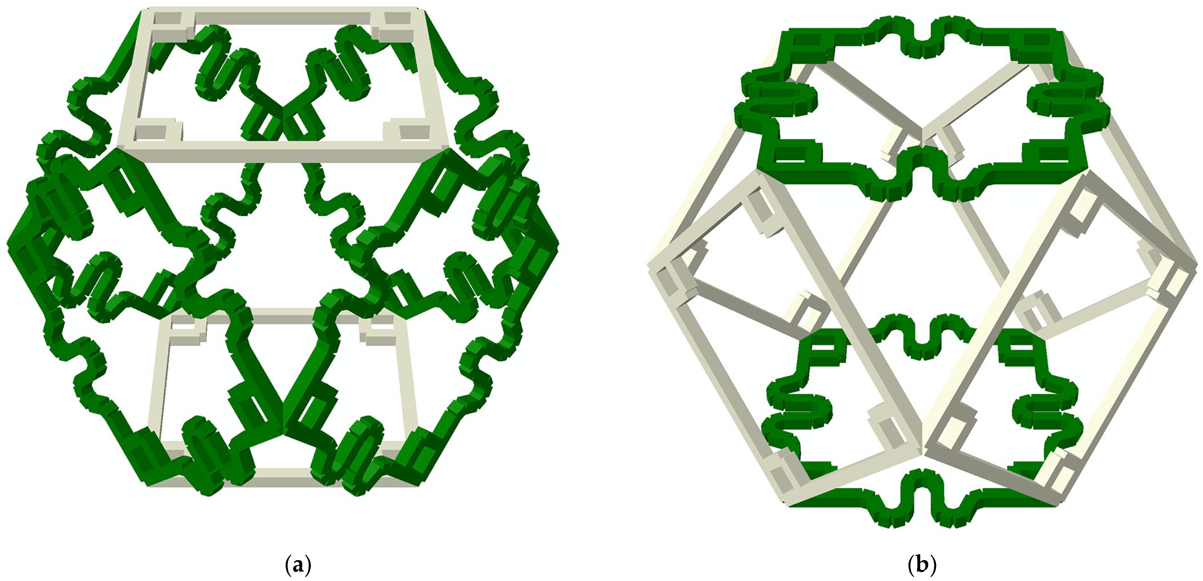
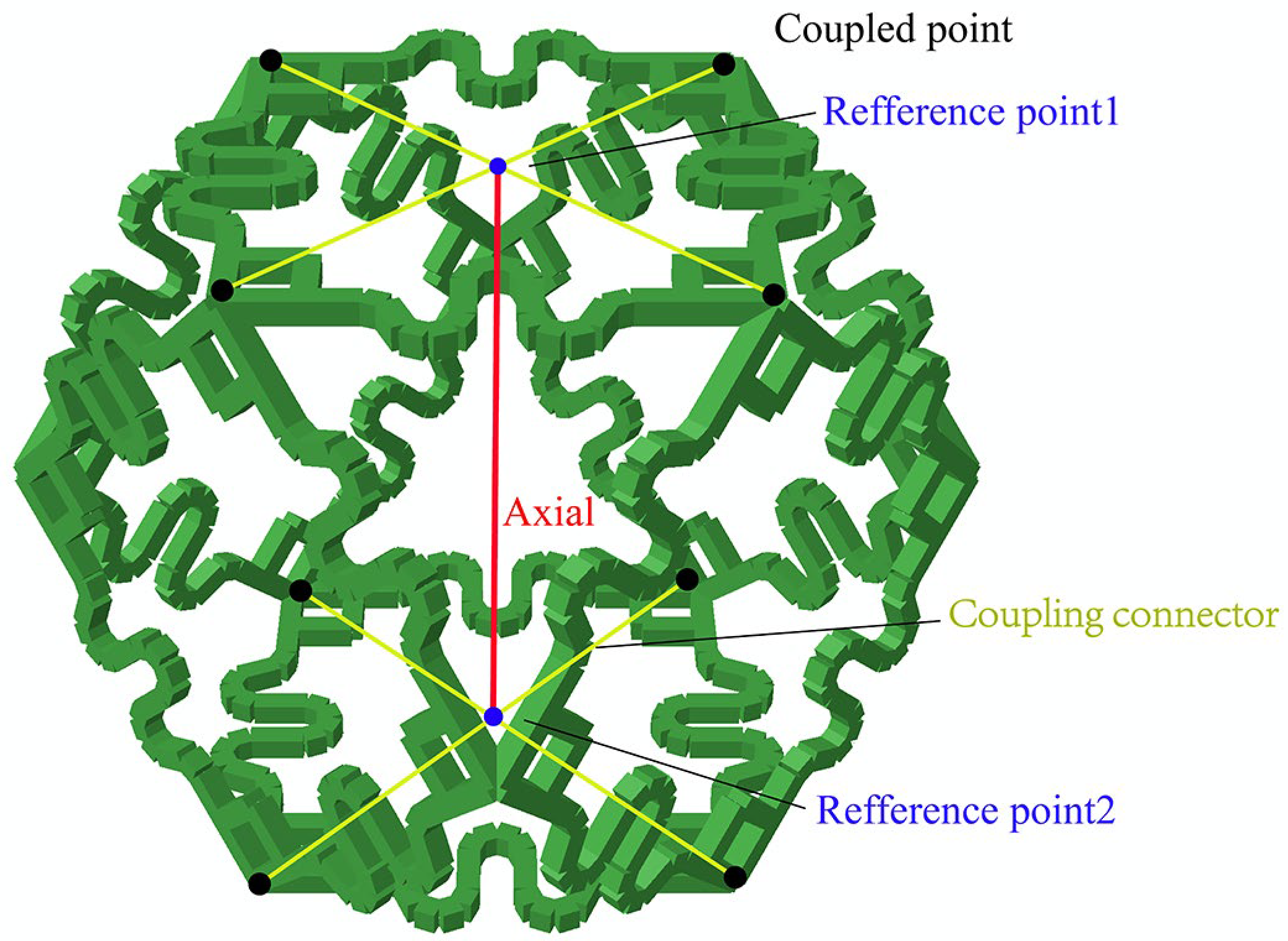
2.2.3. Auxetic Cell
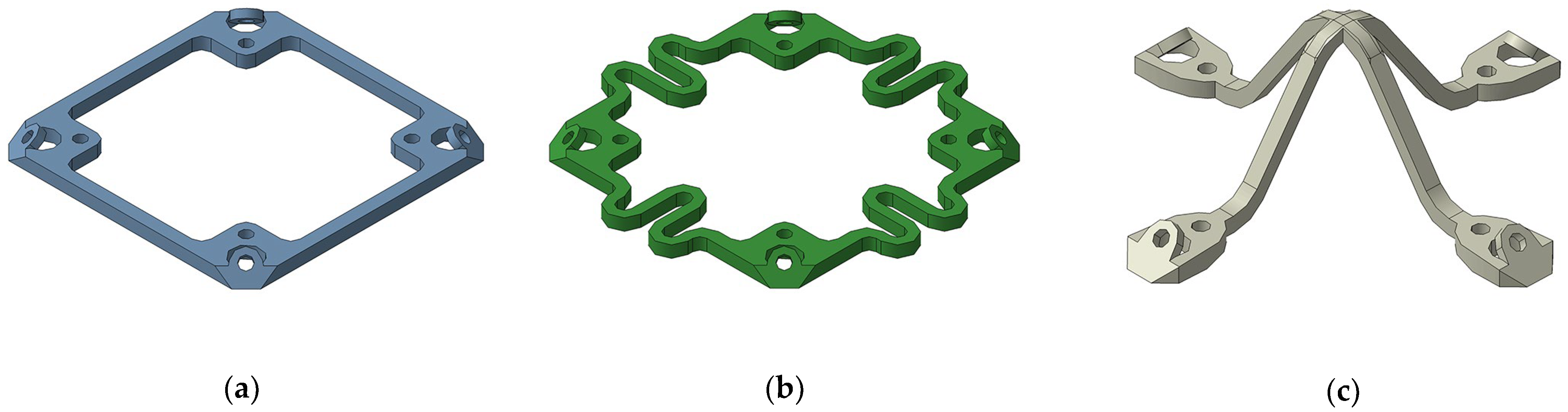
2.3. Derived Cells
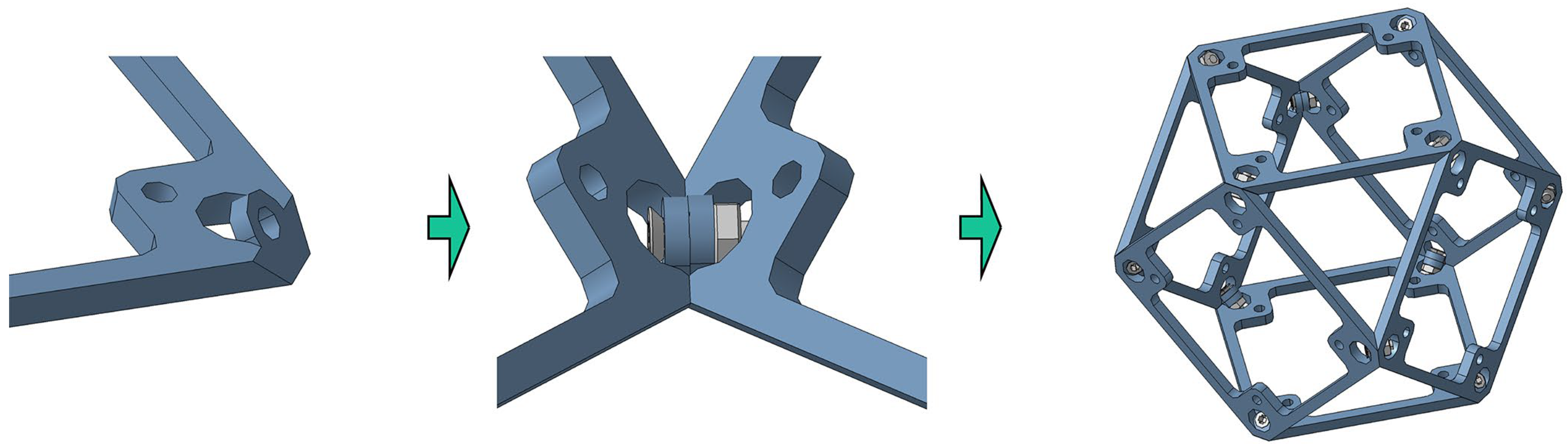
2.4. Reversible Assembly Manner
3. Optimization Methodology
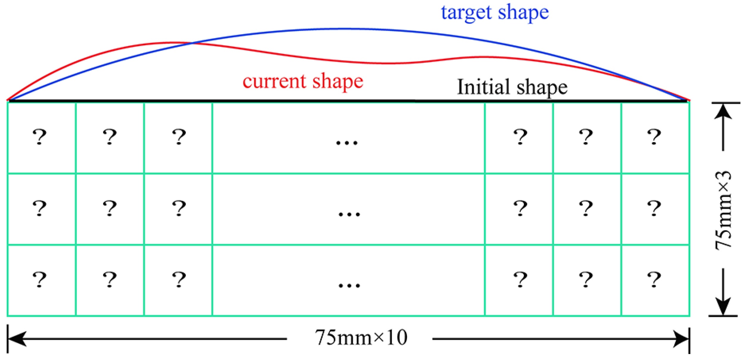
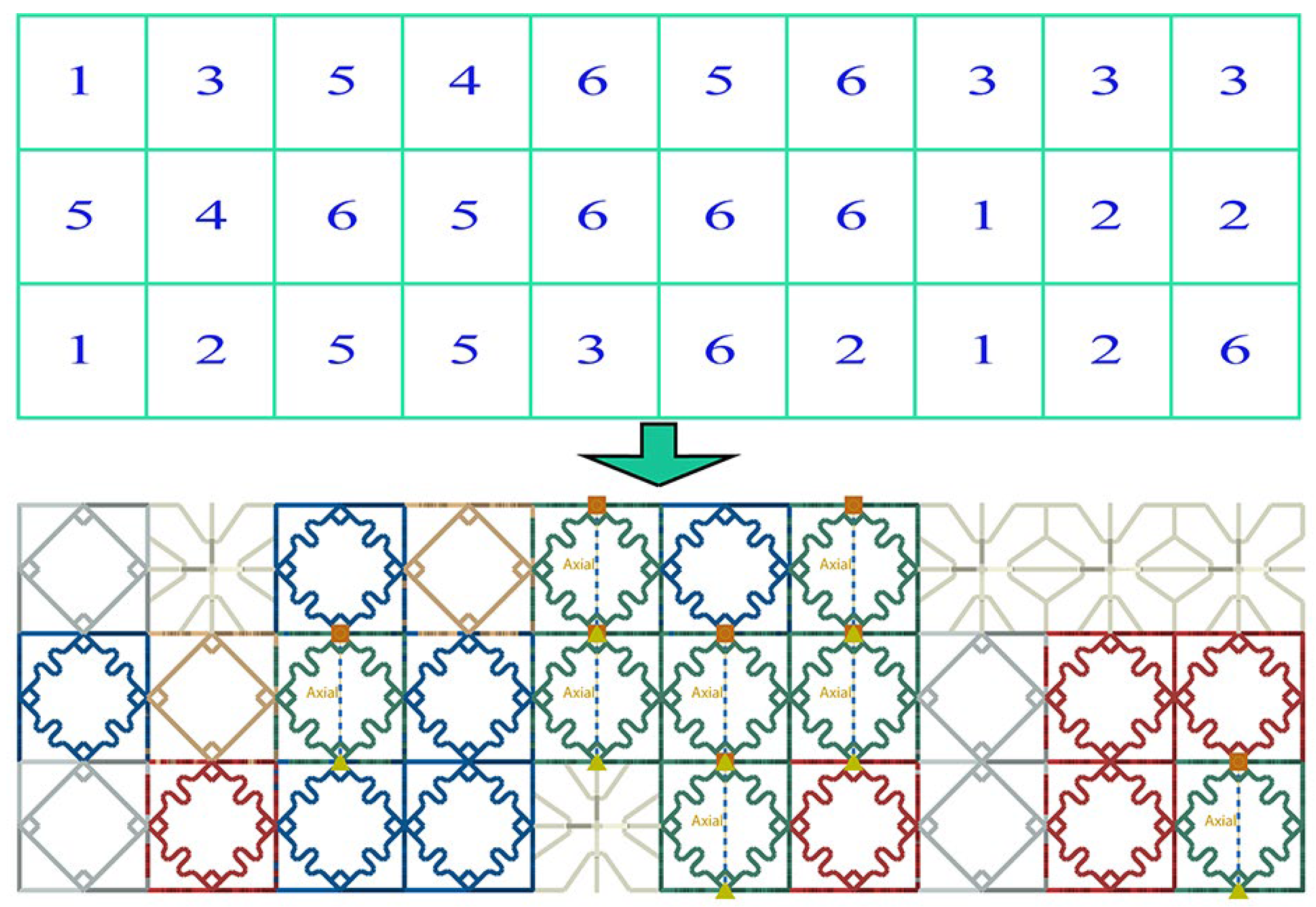
3.1. Encoding and Decoding
3.2. Selection
3.3. Crossover
3.4. Mutation
3.5. Changing Number of Design Variables
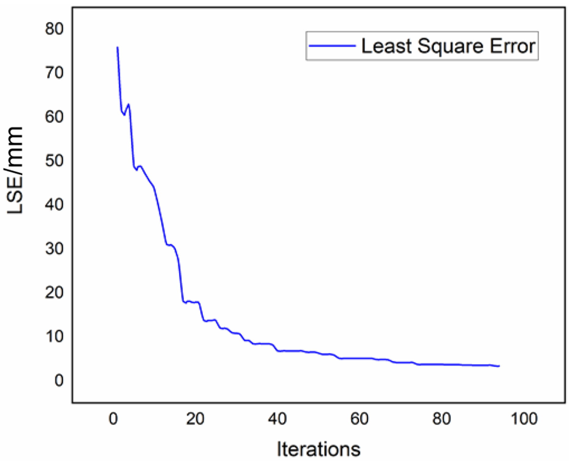
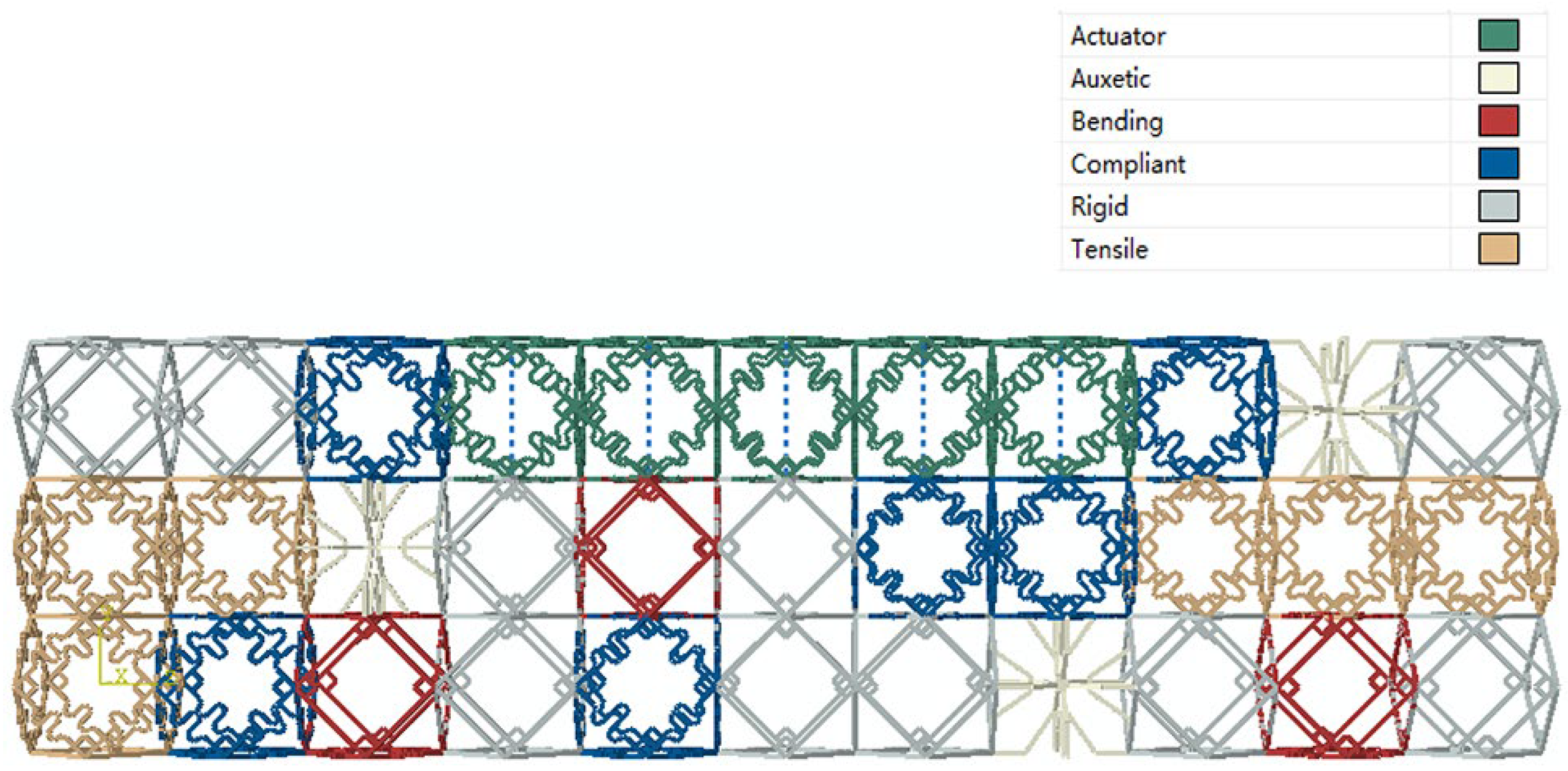
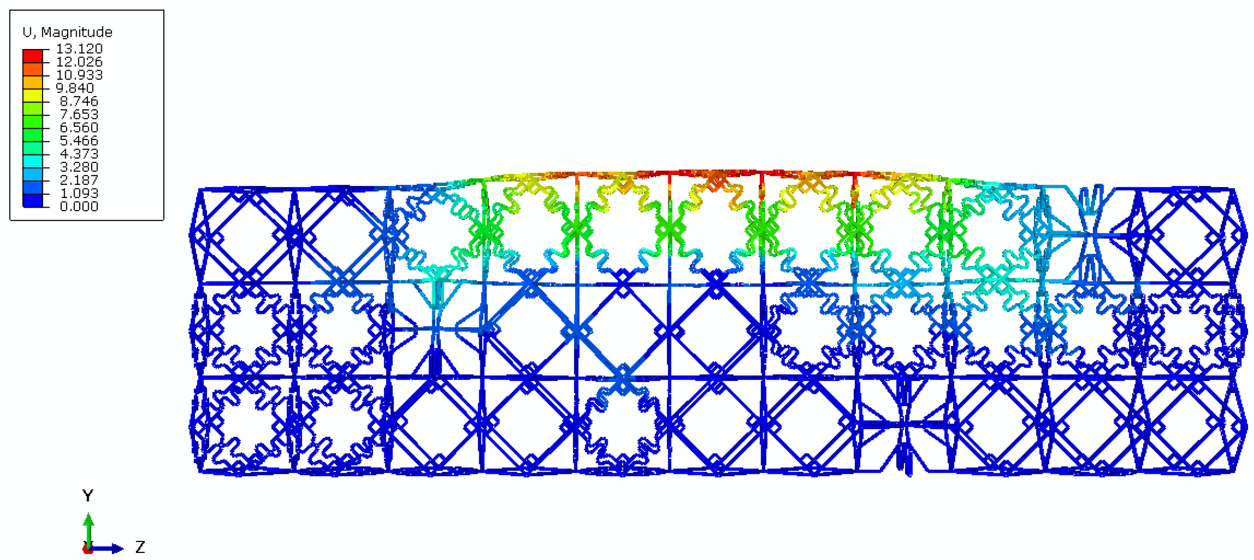
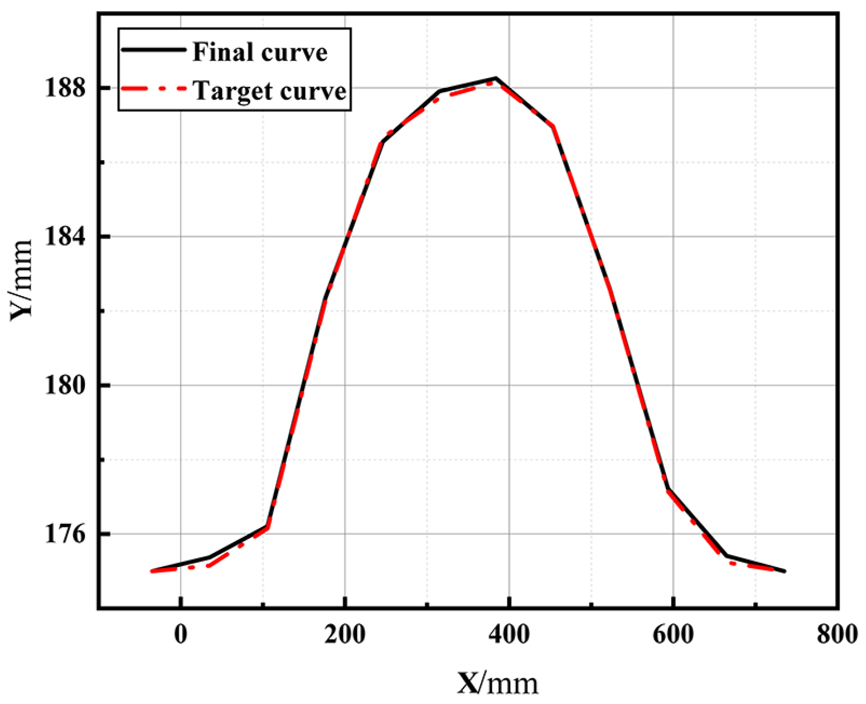
3.6. Optimization Model and Results
4. Conclusions
Author Contributions
Funding
Data Availability Statement
Conflicts of Interest
References
- Barbarino, S.; Bilgen, O.; Ajaj, R.M.; Friswell, M.I.; Inman, D.J. A Review of Morphing Aircraft. J. Intell. Mater. Syst. Struct. 2011, 22, 823–877. [Google Scholar] [CrossRef]
- Li, D.; Zhao, S.; Da Ronch, A.; Xiang, J.; Drofelnik, J.; Li, Y.; Zhang, L.; Wu, Y.; Kintscher, M.; Monner, H.P.; et al. A Review of Modelling and Analysis of Morphing Wings. Prog. Aerosp. Sci. 2018, 100, 46–62. [Google Scholar] [CrossRef] [Green Version]
- Cramer, N.B.; Cellucci, D.W.; Formoso, O.B.; Gregg, C.E.; Jenett, B.E.; Kim, J.H.; Lendraitis, M.; Swei, S.S.; Trinh, G.T.; Trinh, K.V.; et al. Elastic Shape Morphing of Ultralight Structures by Programmable Assembly. Smart Mater. Struct. 2019, 28, 055006. [Google Scholar] [CrossRef] [PubMed] [Green Version]
- De Gaspari, A.; Ricci, S. A Two-Level Approach for the Optimal Design of Morphing Wings Based on Compliant Structures. J. Intell. Mater. Syst. Struct. 2011, 22, 1091–1111. [Google Scholar] [CrossRef]
- Chen, Y.; Yin, W.; Liu, Y.; Leng, J. Structural Design and Analysis of Morphing Skin Embedded with Pneumatic Muscle Fibers. Smart Mater. Struct. 2011, 20, 085033. [Google Scholar] [CrossRef]
- Cramer, N.B.; Cheung, K.; Swei, S.S.-M. Design and Testing of a Lattice-Based Cellular Component Active Twist Wing. In Proceedings of the American Institute of Aeronautics and Astronautics (AIAA), San Diego, CA, USA, 4 January 2016. [Google Scholar]
- McHale, C.; Telford, R.; Weaver, P.M. Morphing Lattice Boom for Space Applications. Compos. Part B Eng. 2020, 202, 108441. [Google Scholar] [CrossRef]
- Chen, Q.; Lv, P.; Huang, J.; Huang, T.-Y.; Duan, H. Intelligent Shape-Morphing Micromachines. Research 2021, 2021, 9806463. [Google Scholar] [CrossRef]
- Özgen, S.; Yaman, Y.; Insuyu, T.; Yilmaz, A.; Şahin, M.; Seber, G.; Ünlüsoy, L.; Sakarya, E.; İnsuyu, T.; Bulvarı, İ.; et al. Morphing Air Vehicle Concepts. In Proceedings of the International Workshop on Unmanned Vehicles-UVW, Istanbul, Turkiye, 10–12 June 2010. [Google Scholar]
- Sun, J.; Guan, Q.; Liu, Y.; Leng, J. Morphing Aircraft Based on Smart Materials and Structures: A State-of-the-Art Review. J. Intell. Mater. Syst. Struct. 2016, 27, 2289–2312. [Google Scholar] [CrossRef]
- Vasista, S.; Tong, L.; Wong, K.C. Realization of Morphing Wings: A Multidisciplinary Challenge. J. Aircr. 2012, 49, 11–28. [Google Scholar] [CrossRef]
- Sofla, A.Y.N.; Meguid, S.A.; Tan, K.T.; Yeo, W.K. Shape Morphing of Aircraft Wing: Status and Challenges. Mater. Des. 2010, 31, 1284–1292. [Google Scholar] [CrossRef]
- Zhu, L.; Sun, G.; Li, H.; Dong, M. Intelligent and Flexible Morphing Wing Technology: A Review. Jixie Gongcheng Xuebao/J. Mech. Eng. 2018, 54, 28–42. [Google Scholar] [CrossRef]
- Joo, J.J.; Marks, C.R.; Zientarski, L.; Culler, A. Variable Camber Compliant Wing-Design. In Proceedings of the 23rd AIAA/AHS Adaptive Structures Conference, Kissimmee, FL, USA, 5–9 January 2015; American Institute of Aeronautics and Astronautics Inc.: Reston, VA, USA. [Google Scholar]
- Gilbert, W.W. Mission Adaptive Wing System for Tactical Aircraft. J. Aircr. 1981, 18, 597–602. [Google Scholar] [CrossRef]
- Popov, A.V.; Grigorie, L.T.; Botez, R.; Mamou, M.; Mébarki, Y. Closed-Loop Control Validation of a Morphing Wing Using Wind Tunnel Tests. J. Aircr. 2010, 47, 1309–1317. [Google Scholar] [CrossRef]
- Schmitz, A.; Horst, P. A Finite Element Unit-Cell Method for Homogenised Mechanical Properties of Heterogeneous Plates. Compos. Part A Appl. Sci. Manuf. 2014, 61, 23–32. [Google Scholar] [CrossRef]
- Bishay, P.L.; Finden, R.; Recinos, S.; Alas, C.; Lopez, E.; Aslanpour, D.; Flores, D.; Gonzalez, E. Development of an SMA-Based Camber Morphing UAV Tail Core Design. Smart Mater. Struct. 2019, 28, 075024. [Google Scholar] [CrossRef]
- Rudenko, A.; Hannig, A.; Monner, H.P.; Horst, P. Extremely Deformable Morphing Leading Edge: Optimization, Design and Structural Testing. J. Intell. Mater. Syst. Struct. 2018, 29, 764–773. [Google Scholar] [CrossRef]
- Vasista, S.; Nolte, F.; Monner, H.P.; Horst, P.; Burnazzi, M. Three-Dimensional Design of a Large-Displacement Morphing Wing Droop Nose Device. J. Intell. Mater. Syst. Struct. 2018, 29, 3222–3241. [Google Scholar] [CrossRef]
- Wang, C.; Haddad Khodaparast, H.; Friswell, M.I.; Magrini, A.; Ponza, R.; Benini, E.; Landersheim, V.; Laveuve, D.; Contell Asins, C. Conceptual-Level Evaluation of a Variable Stiffness Skin for a Morphing Wing Leading Edge. Proc. Inst. Mech. Eng. Part G J. Aerosp. Eng. 2019, 233, 5703–5716. [Google Scholar] [CrossRef] [Green Version]
- Sodja, J.; Martinez, M.J.; Simpson, J.C.; De Breuker, R. Experimental Evaluation of the Morphing Leading Edge Concept. In Proceedings of the 23rd AIAA/AHS Adaptive Structures Conference, Kissimmee, FL, USA, 5–9 January 2015; American Institute of Aeronautics and Astronautics Inc.: Reston, VA, USA. [Google Scholar]
- Asins, C.C.; Landersheim, V.; Laveuve, D.; Adachi, S.; May, M.; Wacker, J.D.; Decker, J. Analysis and Design of a Leading Edge with Morphing Capabilities for the Wing of a Regional Aircraft—Gapless Chord-and Camber-Increase for High-Lift Performance. Appl. Sci. 2021, 11, 2752. [Google Scholar] [CrossRef]
- Baker, D.; Friswell, M.I. Determinate Structures for Wing Camber Control. Smart Mater. Struct. 2009, 18, 035014. [Google Scholar] [CrossRef]
- Cavalieri, V.; de Gaspari, A.; Ricci, S. Optimization of Compliant Adaptive Structures in the Design of a Morphing Droop Nose. Smart Mater. Struct. 2020, 29, 075020. [Google Scholar] [CrossRef] [Green Version]
- Trease, B.; Kota, S. Design of Adaptive and Controllable Compliant Systems with Embedded Actuators and Sensors. J. Mech. Des. Trans. ASME 2009, 131, 1110011–11100112. [Google Scholar] [CrossRef]
- Milojević, A.P.; Pavlović, N.D. Development of a New Adaptive Shape Morphing Compliant Structure with Embedded Actuators. J. Intell. Mater. Syst. Struct. 2016, 27, 1306–1328. [Google Scholar] [CrossRef]
- Geier, S.; Kintscher, M.; Mahrholz, T.; Wierach, P.; Monner, H.-P.; Wiedemann, M. Experimental and Finite Element Analyses of Multifunctional Skins for Morphing Wing Applications. In Proceedings of the Sensors and Smart Structures Technologies for Civil, Mechanical, and Aerospace Systems 2016, Las Vegas, NV, USA, 20 April 2016; SPIE: Washington, DC, USA; Volume 9803, p. 980328. [Google Scholar]
- Kintscher, M.; Wiedemann, M.; Monner, H.P.; Heintze, O.; Kühn, T. Design of a Smart Leading Edge Device for Low Speed Wind Tunnel Tests in the European Project SADE. Int. J. Struct. Integr. 2011, 2, 383–405. [Google Scholar] [CrossRef]
- Yang, Y.; Wang, Z.; Wang, B.; Lyu, S. Optimization, Design and Testing for Morphing Leading Edge. Proc. Inst. Mech. Eng. Part C J. Mech. Eng. Sci. 2020, 095440622094188. [Google Scholar] [CrossRef]
- Alsaidi, B.; Joe, W.Y.; Akbar, M. Computational Analysis of 3D Lattice Structures for Skin in Real-Scale Camber Morphing Aircraft. Aerospace 2019, 6, 79. [Google Scholar] [CrossRef] [Green Version]
- Spadoni, A.; Ruzzene, M. Static Aeroelastic Response of Chiral-Core Airfoils. J. Intell. Mater. Syst. Struct. 2007, 18, 1067–1075. [Google Scholar] [CrossRef] [Green Version]
- Fasel, U.; Keidel, D.; Baumann, L.; Cavolina, G.; Eichenhofer, M.; Ermanni, P. Composite Additive Manufacturing of Morphing Aerospace Structures. Manuf. Lett. 2020, 23, 85–88. [Google Scholar] [CrossRef]
- Keidel, D.; Lienhard, M.; Fasel, U.; Ermanni, P. Design and Testing of a Lattice Morphing Wing. In Proceedings of the ASME 2020 Conference on Smart Materials, Adaptive Structures and Intelligent Systems, Virtual, Online, 15 September 2020; American Society of Mechanical Engineers: New York, NY, USA; p. V001T04A011. [Google Scholar]
- Jenett, B.; Cameron, C.; Tourlomousis, F.; Rubio, A.P.; Ochalek, M.; Gershenfeld, N. Discretely Assembled Mechanical Metamaterials. Sci. Adv. 2020, 6, eabc9943. [Google Scholar] [CrossRef]
- Zhang, H.; Zhang, Z.; Song, C.; Yang, C. A Morphing Wing with Cellular Structure of Non-Uniform Density. Smart Mater. Struct. 2021, 30, 105005. [Google Scholar] [CrossRef]
- Youngren, H. Multi-Point Design and Optimization of a Natural Laminar Flow Airfoil for a Mission Adaptive Compliant Wing. In Proceedings of the 46th AIAA Aerospace Sciences Meeting and Exhibit, Reno, NV, USA, 7–10 January 2008. [Google Scholar]
- Wang, Z.-P.; Poh, L.H. Optimal Form and Size Characterization of Planar Isotropic Petal-Shaped Auxetics with Tunable Effective Properties Using IGA. Compos. Struct. 2018, 201, 486–502. [Google Scholar] [CrossRef]
- Jenett, B.; Cellucci, D. A Mobile Robot for Locomotion through a 3D Periodic Lattice Environment. In Proceedings of the 2017 IEEE International Conference on Robotics and Automation (ICRA), Singapore, 29 May 2017–3 June 2017; IEEE: Singapore; pp. 5474–5479. [Google Scholar]
- Yang, J.; Song, B.; Zhong, X.; Jin, P. Optimal Design of Blended Composite Laminate Structures Using Ply Drop Sequence. Compos. Struct. 2016, 135, 30–37. [Google Scholar] [CrossRef]
- Yang, Y.; Wang, Z.; Lyu, S. Comparative Study of Two Lay-up Sequence Dispositions for Flexible Skin Design of Morphing Leading Edge. Chin. J. Aeronaut. 2021, 34, 271–278. [Google Scholar] [CrossRef]
- Wang, Z.; Yang, Y. Design of a Variable-Stiffness Compliant Skin for a Morphing Leading Edge. Appl. Sci. 2021, 11, 3165. [Google Scholar] [CrossRef]
- Soremekun, G.; Gürdal, Z.; Kassapoglou, C.; Toni, D. Stacking Sequence Blending of Multiple Composite Laminates Using Genetic Algorithms. Compos. Struct. 2002, 56, 53–62. [Google Scholar] [CrossRef]
- Süli, E.; Mayers, D.F. An Introduction to Numerical Analysis; Cambridge University Press: Cambridge, UK, 2003; ISBN 978-0-521-00794-8. [Google Scholar]
- Wang, D.; Abdalla, M.M. Global and Local Buckling Analysis of Grid-Stiffened Composite Panels. Compos. Struct. 2015, 119, 767–776. [Google Scholar] [CrossRef]
- Jenett, B.; Calisch, S.; Cellucci, D.; Cramer, N.; Gershenfeld, N.; Swei, S.; Cheung, K.C. Digital Morphing Wing: Active Wing Shaping Concept Using Composite Lattice-Based Cellular Structures. Soft Robot. 2017, 4, 33–48. [Google Scholar] [CrossRef]


| Tensile Modulus | Poisson’s Ratio | Ultimate Tensile Strength | Elongation | Method | |
|---|---|---|---|---|---|
| Non-cured | 0.45 Gpa | 0.3 | 18.6 MPa | 0.67 | ASTM D 638-10 |
| Post-cured | 1.26 Gpa | 0.3 | 31.8 Mpa | 0.49 | ASTM D 638-10 |
| Rigid Cell | Compliant Cell | Auxetic Cell | Tensile Cell | Bending Cell | Actuator Cell | |
|---|---|---|---|---|---|---|
| Number of the unit cells | 10 | 6 | 3 | 6 | 3 | 5 |
| Material volume of a unit cell (m3) | 1.1090 × 10⁻⁵ | 1.4110 × 10⁻⁵ | 0.9059 × 10⁻⁵ | 1.3103 × 10⁻⁵ | 1.2096 × 10⁻⁵ | 1.4110 × 10⁻⁵ |
| Weight of a unit cell (kg) | 1.1145 × 10⁻² | 1.4180 × 10⁻² | 0.9104 × 10⁻² | 1.3168 × 10⁻² | 1.2156 × 10⁻² | 6.4180 × 10⁻² |
Publisher’s Note: MDPI stays neutral with regard to jurisdictional claims in published maps and institutional affiliations. |
© 2022 by the authors. Licensee MDPI, Basel, Switzerland. This article is an open access article distributed under the terms and conditions of the Creative Commons Attribution (CC BY) license (https://creativecommons.org/licenses/by/4.0/).
Share and Cite
Wang, Z.; Wu, Q.; Lu, Y.; Bao, P.; Yang, Y.; Li, D.; Sun, X.; Xiang, J. Design of a Distributedly Active Morphing Wing Based on Digital Metamaterials. Aerospace 2022, 9, 762. https://doi.org/10.3390/aerospace9120762
Wang Z, Wu Q, Lu Y, Bao P, Yang Y, Li D, Sun X, Xiang J. Design of a Distributedly Active Morphing Wing Based on Digital Metamaterials. Aerospace. 2022; 9(12):762. https://doi.org/10.3390/aerospace9120762
Chicago/Turabian StyleWang, Zhigang, Qi Wu, Yifei Lu, Panpan Bao, Yu Yang, Daochun Li, Xiasheng Sun, and Jinwu Xiang. 2022. "Design of a Distributedly Active Morphing Wing Based on Digital Metamaterials" Aerospace 9, no. 12: 762. https://doi.org/10.3390/aerospace9120762