
Flow Mechanism of a New Concept Transonic Tandem Fan Stage under the Design and Off-Design Conditions

1
Key Laboratory of Light-Duty Gas-Turbine, Institute of Engineering Thermophysics, Chinese Academy of Sciences, Beijing 100190, China
2
University of Chinese Academy of Sciences, Beijing 100049, China
3
Innovation Academy for Light-Duty Gas Turbine, Chinese Academy of Sciences, Beijing 100190, China
*
Authors to whom correspondence should be addressed.
Aerospace 2022, 9(11), 686; https://doi.org/10.3390/aerospace9110686
Submission received: 19 September 2022
/
Revised: 25 October 2022
/
Accepted: 25 October 2022
/
Published: 3 November 2022
(This article belongs to the Special Issue Aerodynamics Design)
Abstract
:A detailed numerical simulation of a transonic tandem fan stage was conducted, and the change rule of the flow structure inside the fan stage under the design and off-design conditions was discussed to determine the internal flow mechanisms. The results demonstrate that the total pressure ratio of the fan stage steadily increases with the rotating speed, exhibiting an approximately quadratic growth rate. The peak efficiency reaches the maximum at 80% design speed and rapidly declines under the overspeed condition. Furthermore, the peak efficiency point for different rotating speeds was investigated. The changes in the flow features, such as shock wave/boundary layer interaction and radial migration of low-energy fluids, mainly determine the isentropic efficiency at the higher span. At the middle-lower span, higher or lower inflow relative Mach number increases the flow loss. Moreover, the strength of the tip vortex and wake affect the flow loss at the lower span, while the radial motion of the former flow structure dominated by the equivalent inertial force is another essential factor. Under the high-speed condition, the gain of a high-throughflow fan on choke mass flow can be exhibited. However, the throat position causes an abnormal change under the overspeed condition.
1. Introduction
For aero-engines, the rotating speed varies over a wide range under different operating conditions, such as ground idling, take-off, level flight, and afterburner. Additionally, the aerodynamic performance of the fan changes, which affects the overall engine. Nowadays, driven by the demands for greater energy efficiency and environmental friendliness in the aviation field, the aerodynamic performance and flow mechanism of the fan stage under different rotating speeds needs to be particularly investigated.
A high-throughflow fan [1,2,3,4] is a relatively novel aerodynamic concept. A tandem rotor is established by installing a partial-span booster rotor in front of the fan rotor, effectively improving the flow capacity and core pressure ratio. It has broad application prospects for reducing the engine weight and fuel consumption. Tandem blades have been widely studied in centrifugal compressors [5,6,7] and axial compressors due to their high load and high efficiency characteristics. An axial flow tandem rotor was first studied in the 1970s, and P&W conducted investigations on subsonic [8] and transonic [9] tandem rotors with the support of NASA. Since then, the research on tandem rotors has progressed in two directions: subsonic and transonic conditions. Owing to the less complicated flow phenomenon in the blade passage, a tandem rotor develops more rapidly under the subsonic condition than the transonic condition [10,11,12,13,14,15,16,17]. Shock waves were usually present in the forward blade passage of a tandem rotor, while the aft blade of the tandem rotor was in a positive prewhirl condition, which inevitably increased the design difficulty of the downstream stator. Therefore, the early aerodynamic design of a transonic tandem rotor faced the dual problems of insufficient isentropic efficiency (ηisen) and stall margin. In 1971, Burger and Keenan [8] designed a single-stage tandem rotor compressor with an inlet hub to tip ratio of 0.5, a tip tangential velocity of 490 m/s, a total pressure ratio (π) of 1.94, and an isentropic efficiency of only 83.1%. Furthermore, under the radial and circumferential distortion inflow conditions, the peak isentropic efficiency decreased to 77.8% and 74.4%, respectively. In 1972, Urasek and Janetzke [18] yielded a stall margin of about 10% for a transonic tandem rotor. In 2003, Hasegawa [19] designed a single-stage fan with a tandem rotor, which had a total pressure ratio as high as 2.2 but an isentropic efficiency of only 77%. The stall margin at the design point was about 10%, and the mass flow () margin was very small. In tests, the loss at the tip was significantly greater than that at the hub. In the same year, Sakai [20] proposed a transonic tandem rotor with an isentropic efficiency of 85% and a stall margin of 10%. However, recently, with a deep understanding of three-dimensional (3D) design and tandem concepts, the problems of isentropic efficiency and margin of transonic tandem rotors have been well-resolved. In 2017, Mohsen [21] redesigned the Rotor 37 and modified it to a tandem rotor with axial division. Moreover, through further analysis and design optimization, they improved the rotor aerodynamic performance over a wide operating range and increased the total pressure ratio and isentropic efficiency at the design point by 17% and 2%, respectively. In 2018, Song [22] optimized the stacking line of a high-loading transonic tandem rotor. Compared to the baseline, the isentropic efficiency of the forward-sweep, positive-bow, and compound sweep rotors near the design point was increased by 1%, 1.03%, and 1.47%, respectively. Additionally, the stall margin of the positive-bow rotor was increased by 23%. Qian [23,24] and Han [25] conducted considerable mechanism research on the near stall condition of a transonic tandem rotor and clarified the important role of the tip leakage flow. Zhou [3,4] studied the matching characteristics between the forward and aft rotors of the high-throughflow fan stage, and clarified the flow mechanism of the potential effect and the tip vortex (TV) for a booster rotor under the design speed condition in the overall stage.
Based on the above description of transonic tandem rotors, most research focuses on the matching characteristics or 3D modeling of the forward and aft blades. To our knowledge, no study in the literature discusses the performance and flow characteristics for a transonic tandem fan under the off-design rotating speed conditions. However, the rotating speed of a turbofan engine generally considerably varies under different flight conditions. The aerodynamic performance of a high-throughflow fan under different rotating speeds will inevitably exhibit a gain or deficit. However, the flow mechanism that causes the change in the performance has not been studied and clarified. Therefore, considering future engineering applications, the performance change rule for the tandem fan stage under the off-design speed condition needs to be investigated to promote the understanding of the mechanism of internal typical flow features and guide aerodynamic design.
In this paper, a full 3D numerical simulation method that is verified by experimental results was employed to compare and analyze the differences among the design speed and multiple off-design speed conditions, including overspeed and partial speed conditions of a high-throughflow fan. First, the change trend of the aerodynamic characteristic curves at different speeds was obtained and analyzed. Then, the overspeed and partial speed conditions were comprehensively compared, and the relationship between the typical flow features inside the tandem rotor and the isentropic efficiency was established. Finally, the flow mechanism of the flow capacity gain was studied in comparison to the baseline conventional fan.
2. Study Cases and Numerical Simulation Methodology
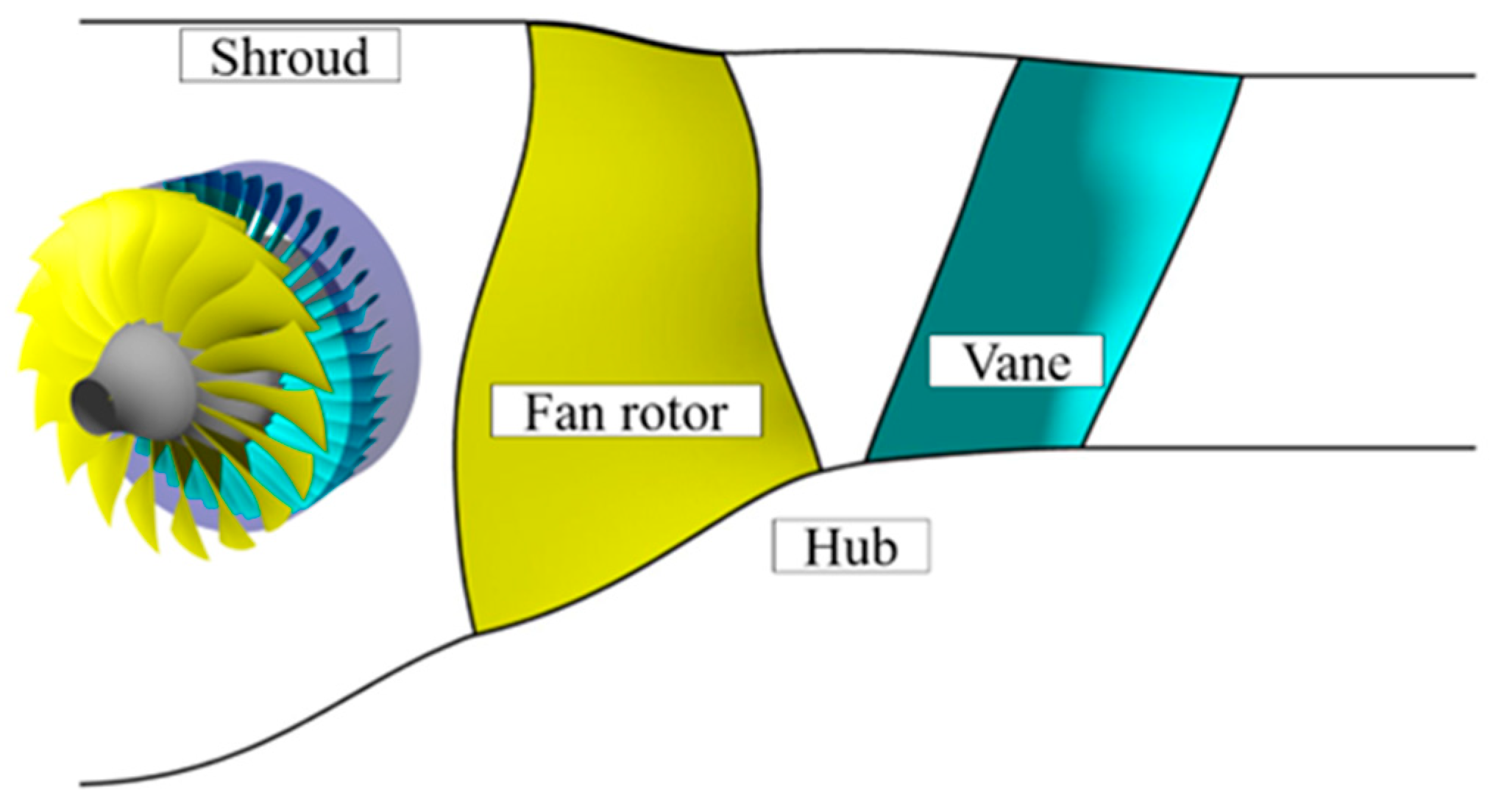
Figure 1 shows the 3D and meridional surface diagram of the baseline fan stage, which comprises a fan rotor and stator. The fan rotor has the characteristics of wide chord and compound sweep, and the number of blades is 18. The stator has the characteristics of large-scale backward sweep and end bending, and the number of blades is 43. Table 1 presents several key geometric and aerodynamic design parameters.
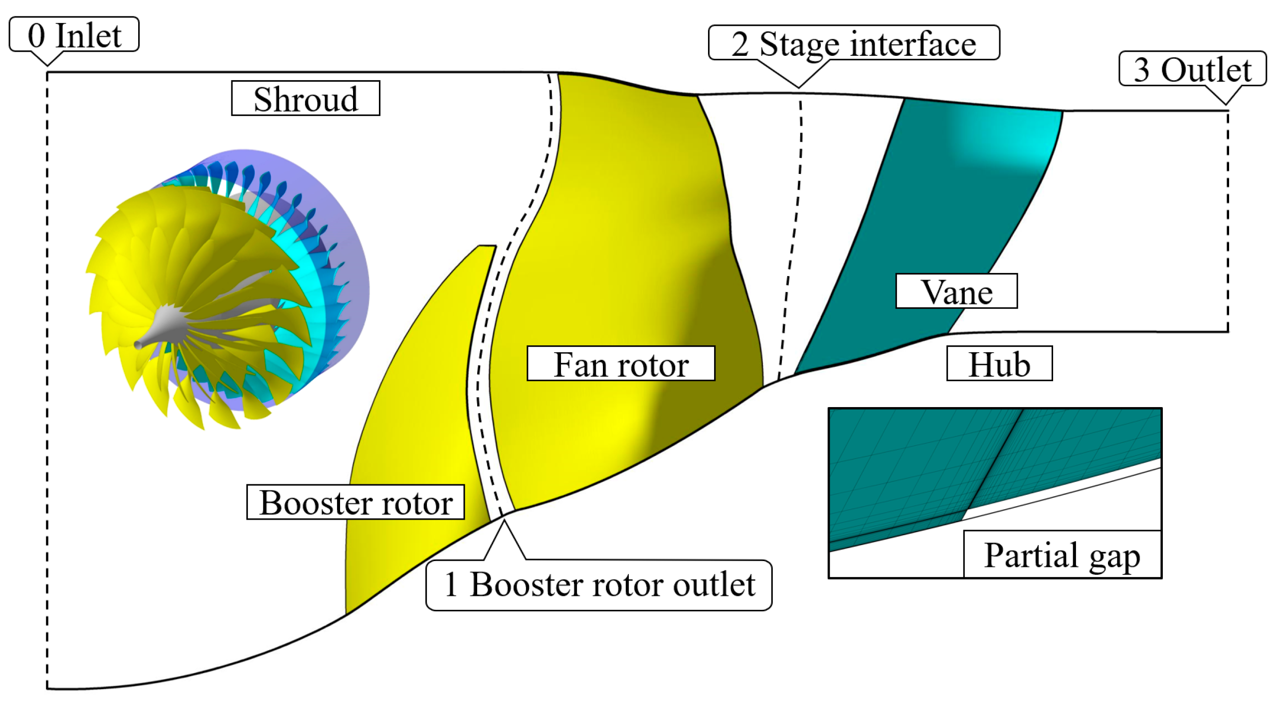
Herein, a high-throughflow fan stage modified from the abovementioned conventional fan stage is employed, which comprises three blade rows: the partial-span booster rotor, fan rotor, and stator. As the booster rotor and fan rotor create the tandem rotor concept, two design parameters were introduced in addition to those of the baseline fan stage: the axial relative position parameter axial overlap (AO) and the circumferential relative position parameter percent pitch (PP). They are shown in Figure 2 and defined as follows:
where Δx represents the axial distance between the trailing edge (TE) of the booster rotor and the leading edge (LE) of the fan rotor, Cx represents the axial chord length of the booster rotor, s represents the circumferential distance between the chordwise extension of the booster rotor and the LE of the fan rotor, and t represents the blade pitch of the booster rotor. Figure 3 and Table 2 present the schematic of the 3D structure and several key design parameters, respectively. The span of the booster rotor is 60%. Additionally, 70%, 80%, and 90% design speeds (N1, N2, and N3) were selected to study the partial speed conditions (the 100% design speed is termed as N4), and the 105% design speed (N5) was selected to study the overspeed condition.
Commercial software ANSYS CFX was employed to solve the full 3D steady-state Reynolds-averaged Navier–Stokes equations. Furthermore, the k–ω-based SST turbulence model was employed to solve the Reynolds stress. The high-resolution scheme was used to calculate the convection term. A total temperature of 288.15 K and total pressure 101,325 Pa were applied with an axial velocity as the inlet boundary condition, and the turbulence intensity was fixed at 5%. The average static pressure was applied for the outlet boundary condition. The mixing plane method was used to transfer the flow information between the rotor and stator interface. The surfaces of the blades and endwalls are set as the adiabatic and no-slip boundary conditions, respectively. The rotor and its connected hub are set as rotating, and the other surfaces are set as stationary. The performance curve of the fan stage is obtained by gradually increasing the backpressure.
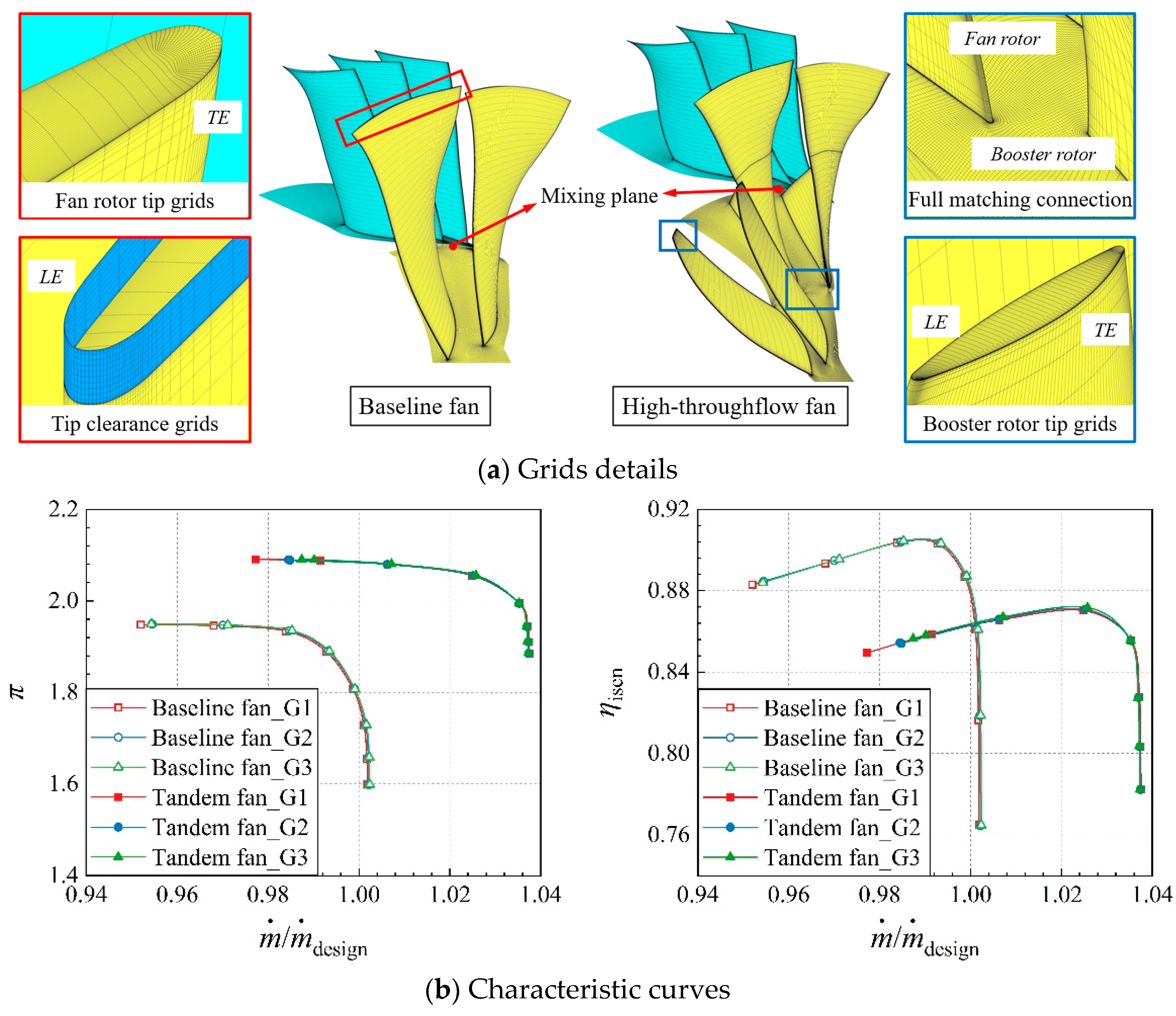
Block-structured grids are employed for the numerical simulation. The passages of the rotor and stator are independently generated by the automatic mesh generator NUMECA IGG/Autogrid5, and full matching grids are used for the tandem rotor. O4H and O topologies are applied to the blade surfaces and the tip gap of the rotor, respectively. According to the requirements of the turbulence model, the normalized height of the first layer of the mesh y+ is approximately one, and the numerical simulation grid is shown in Figure 4a. First, the grid independence of the baseline fan and high-throughflow fan is verified, and three sets of grids with different densities are selected for numerical simulation. The numbers of coarse grid G1 nodes for the baseline fan and high-throughflow fan are 1.2 million and 1.9 million, respectively; the medium grid G2 and fine grid G3 are obtained based on the refinement of G1. Figure 4b shows the performance of different grid configurations. Additionally, the normalized mass flow is a dimensionless parameter, which is normalized by the . The results demonstrate that the grid independence has been satisfied when the number of grid nodes for the baseline fan reaches 2.4 million and the number of grid nodes for the high-throughflow fan reaches 3.5 million (for grid G2, the numbers of grid nodes for the baseline fan in the rotor passage and stator passage are 1.6 million and 0.8 million, respectively; the number of grid nodes for the high-throughflow fan in the tandem rotor passage and stator passage are 2.7 million and 0.8 million, respectively).
3. Experimental Approach and Numerical Simulation Validation
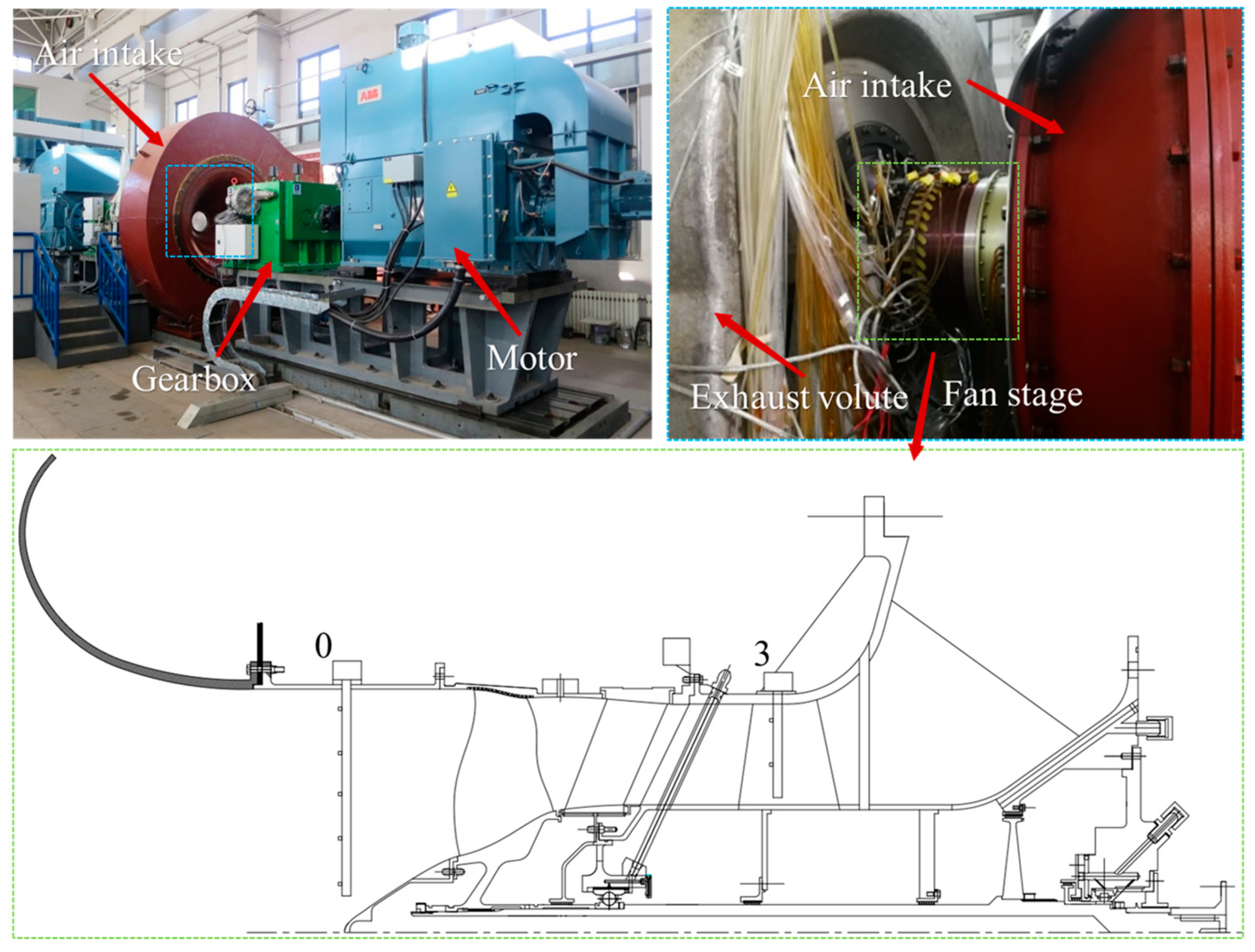
To verify the reliability of the abovementioned numerical simulation methodology, the baseline fan stage was employed for validation. The experiment is performed on a fan/compressor test rig with a maximum shaft power of 3 MW of the Institute of Engineering Thermophysics, Chinese Academy of Sciences. Figure 5 presents the physical display of the test rig. The fan stage is connected to the gearbox through the coupling installed at the end of the shaft, and the gearbox is driven by a 3 MW motor. A static pressure probe and an orifice flowmeter are installed at the bell mouth, and pressure and temperature probes are installed at sections 0 and 3. After collecting the original data, π, ηisen, and , other aerodynamic performance parameters of the fan stage can be obtained. π, ηisen, and , respectively, are defined as follows:
where p represents the pressure, T represents the temperature, kw represents the correction factor, A represents the aera of the bell-mouth, subscripts 0 and 3 represent the inlet and outlet of the overall stage, respectively, and superscript * represents the total parameter.
The uncertainty analysis is an important part of the experimental results. In terms of the fan’s total pressure ratio, the probes used are the total pressure transducers. The limit relative error of the total pressure transducers is , and the limit absolute error of the total temperature transducers is 0.15 K. Subsequently, the relative uncertainty of π and introduced by the measurement chain and calibration process can be deduced as follows:
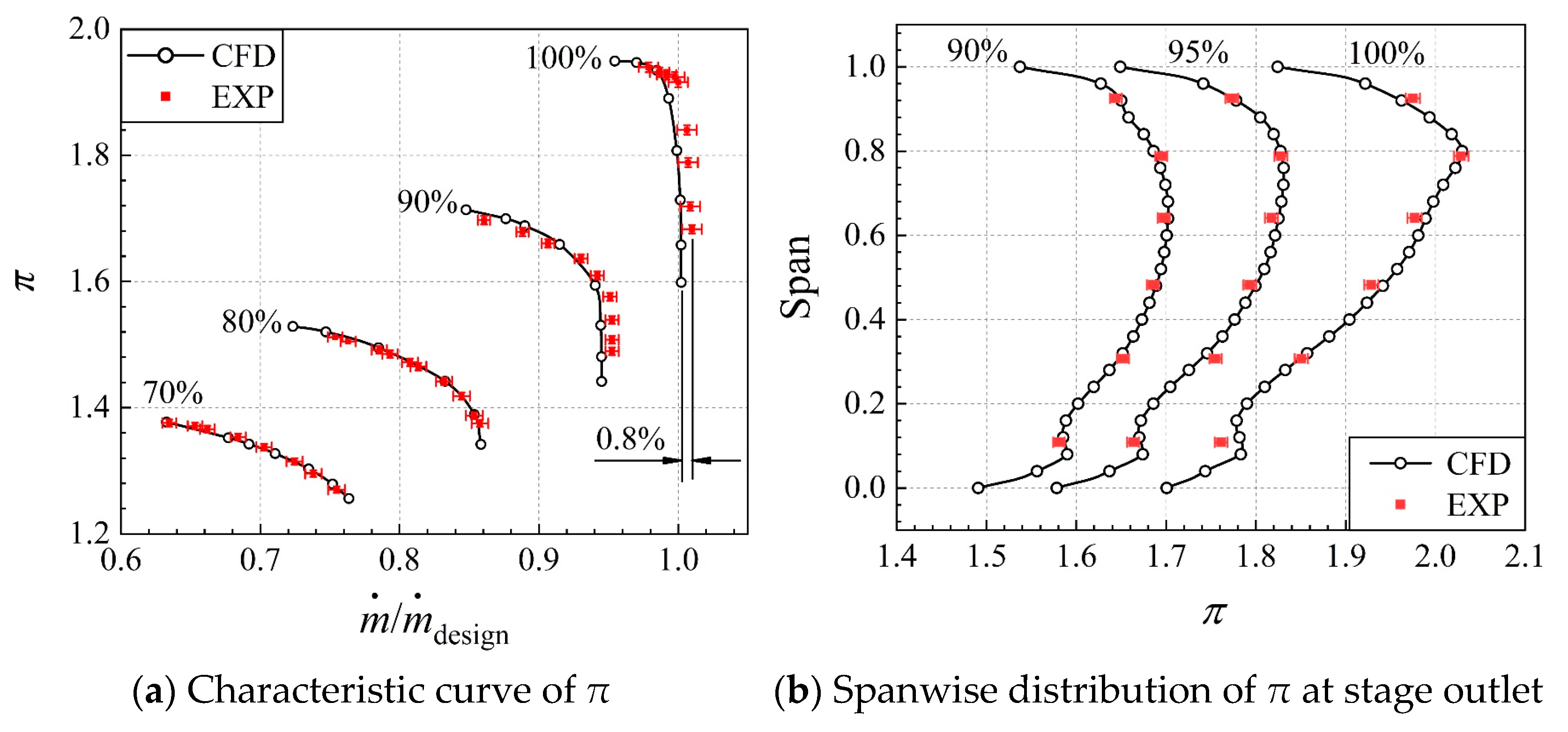
where e represents the relative measurement error. Therefore, the relative uncertainties of the fan total pressure ratio are determined to be 0.4% at each operating speed, and the relative uncertainties of the mass flow are determined to be approximately 0.7% at each operating rotating speed. Then, the numerical result and experiment result with relative error bars are compared for different speeds of the baseline fan stage under the design and off-design speed conditions, as shown in Figure 6. The π characteristic curves of the fan stage obtained via numerical calculations and experimental measurements well agree at each speed. Overall, through numerical simulation, the variation trend of the performance and amplitude of π is reproduced. The spanwise distribution of π at the outlet under the 100%, 95%, and 90% design speed of the peak efficiency point (PEP) is also compared, and the change trend and amplitude are basically the same. Based on the above comparisons, the numerical simulation method adopted in this paper achieves high reliability and can be used for subsequent research.
4. Results and Discussions
The results are presented in four different subsections. The first subsection discusses the aerodynamic performance of the tandem fan stage under different rotating speeds. In the second subsection, the change rule of the choke mass flow of the tandem fan stage with the rotating speed is determined, and the internal flow mechanism is investigated by establishing a physical model. In the third subsection, the reason for the difference of ηisen in the overspeed condition is clarified by analyzing the flow features near the mid-span and tip region in the tandem rotor domain. Finally, in the fourth subsection, the reasons for the difference in the spanwise distribution of ηisen under the partial speed condition are explored, and the radial migration trend of TV under the partial speed condition is clarified.
4.1. Aerodynamic Performance at the Design and Off-Design Rotating Speeds
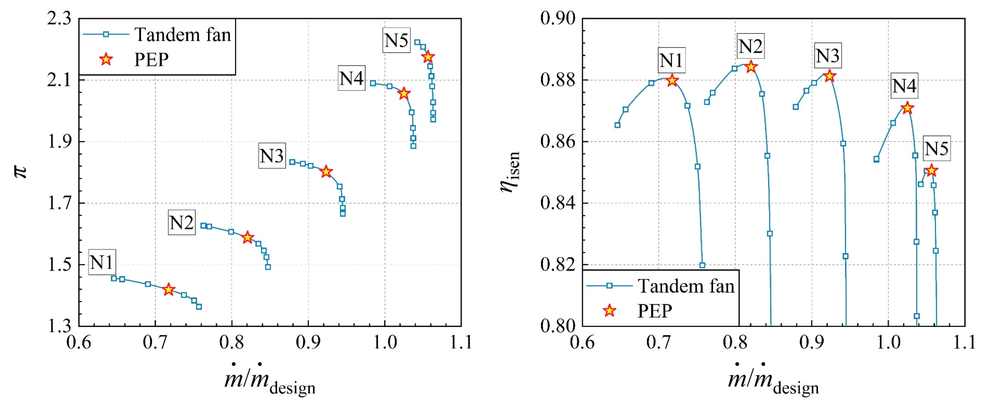
At partial speeds, the inflow at the middle-higher span of the fan rotor gradually changes from supersonic to transonic and that at the lower span gradually changes from transonic to subsonic. When the rotating speed of the tandem rotor exceeds N4, the intensity of the shock wave in the blade passage increases and the inflow at the lower span is transformed into supersonic. Therefore, the aerodynamic performance of the high-throughflow fan greatly changes. Figure 7 displays the performance curves under typical rotating speeds (N1, N2, N3, N4, and N5). From the change of π, the growth rate is relatively stable, which is positively correlated with the rotating speed. In terms of ηisen, the fan stage reaches a high level at N2. At this point, ηisen decreases when the speed is either increased or decreased. As for , it mainly involves two aspects: one is the compression intensity of the airflow in front of the aerodynamic throat, which can be characterized by π and the second is the area of the aerodynamic throat. The aerodynamic throat of the fan stage is usually located in the stator. It is extremely difficult to obtain the area in 3D flow. Thus, only qualitative analysis can be conducted. As the rotating speed increases, is positively related to the rotating speed due to the increased intensity of airflow compression. Since the analysis of aerodynamic performance from the characteristic curve is only qualitative, PEP and choke point at each speed were further selected for comparison.
To describe the relative change trend of different aerodynamic parameters under various speed conditions, the variation of parameters corresponding to each speed relative to N4 is calculated, and the expression is as follows:
where x represents different aerodynamic parameters, including π and ηisen under PEP and . The relative change obtained using the above expression is shown in a columnar diagram in Figure 8. With increasing rotating speed, π and increase and the growth rate of π is promoted; in contrast, the growth rate of decreases, especially when N4 rises to N5, and the relative increment decreases to 3.1%, exhibiting a relatively abnormal change. As for ηisen, it is consistent with the characteristic curve analysis, but ηisen sharply decreases in the overspeed condition. However, under the partial speed conditions, ηisen obviously improves, but the internal mechanism is not yet clear. Generally, different rotating speeds lead to massive changes in the typical flow structure inside the tandem rotor.
4.2. Over-Speed Operating Condition
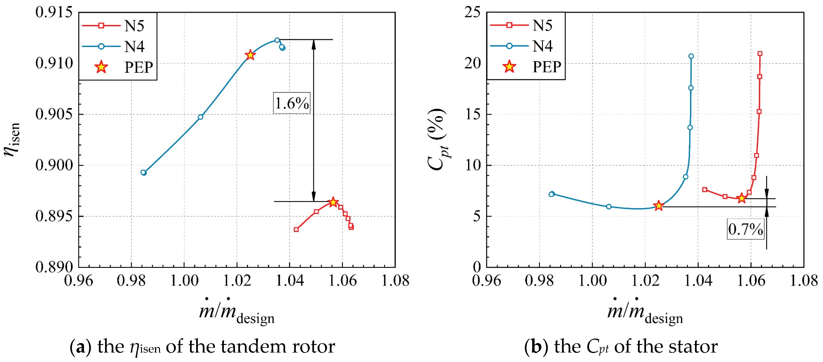
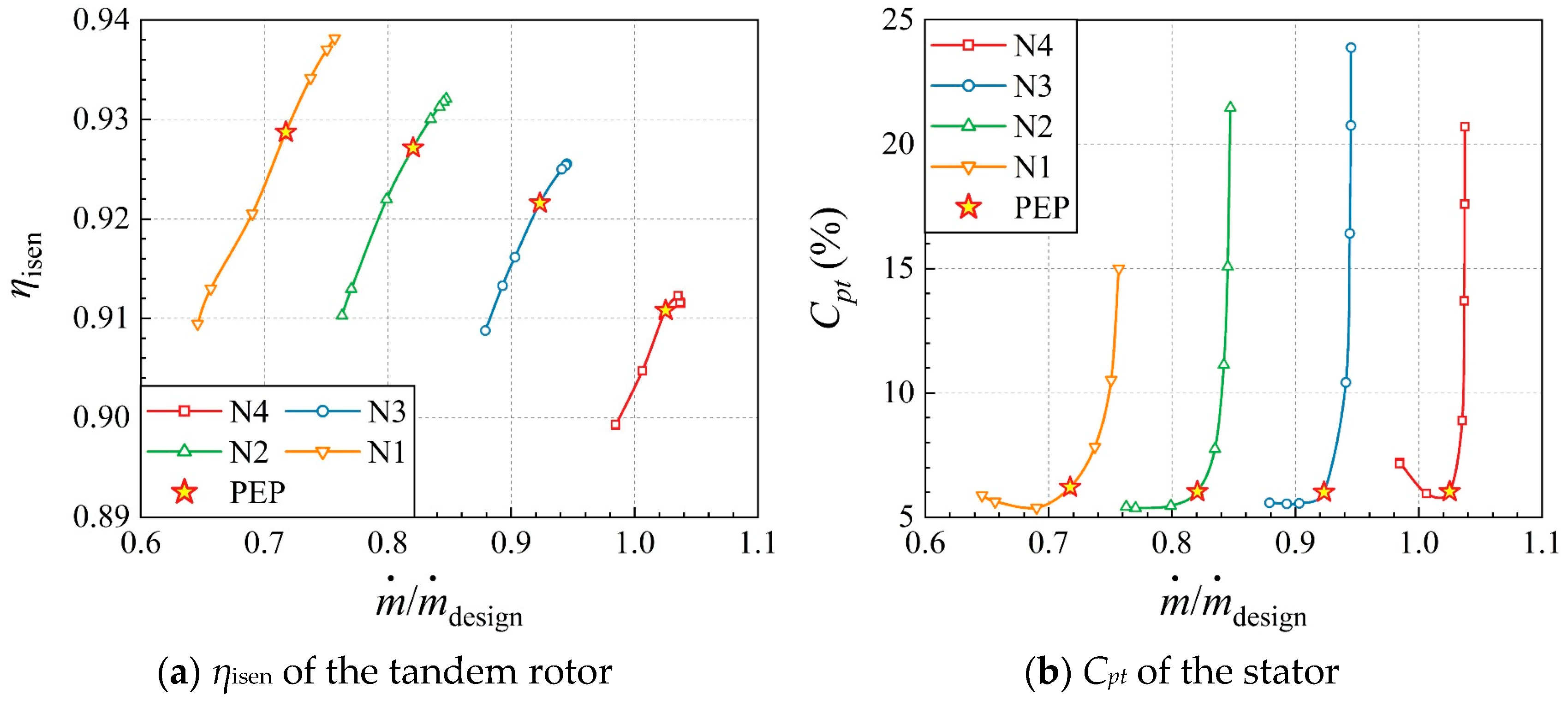
Under the overspeed condition, the peak efficiency of the high-throughflow fan stage sharply decreases, which is about 2.3%. Therefore, the aerodynamic performance of each component needs to be separately analyzed. Figure 9 shows the characteristic curves of ηisen and the total pressure loss coefficient at N4 and N5 of the high-throughflow fan, and the PEP is denoted in the figure. The total pressure loss coefficient is expressed by Cpt:
where p represents the pressure, subscripts 2 and 3 represent the inlet and outlet of the stator, respectively, and superscript * represents the total parameter. The ηisen of the tandem rotor considerably decreases under the overspeed condition, and the maximum difference is about 1.6%. The Cpt of the stator slightly changes, with a difference of approximately 0.7%. Therefore, it can be preliminarily predicted that the main component causing the reduction of ηisen is the tandem rotor domain, and the additional loss caused by the stator domain is not an essential factor. However, in-depth comparative analysis needs to be performed for the aerodynamic performance under PEP to determine the reason of the decline of ηisen.
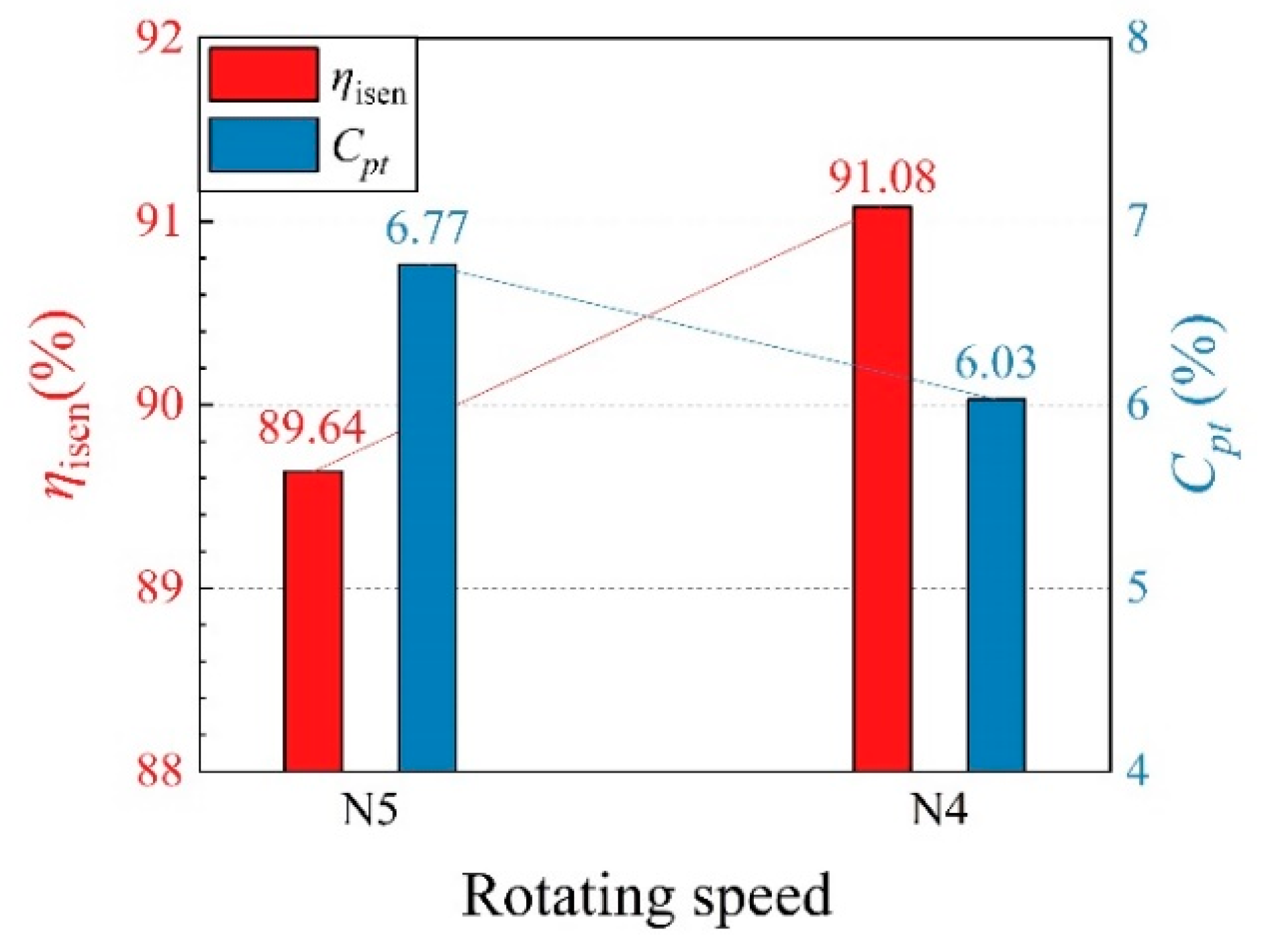
Figure 10 demonstrates the ηisen and Cpt histograms under PEP. As shown in the figure, ηisen decreases by about 1.5%, Cpt increases by about 0.7%, and the efficiency loss of the tandem rotor is more pronounced. Therefore, the subsequent analysis of the related flow structure will focus on the rotor domain.
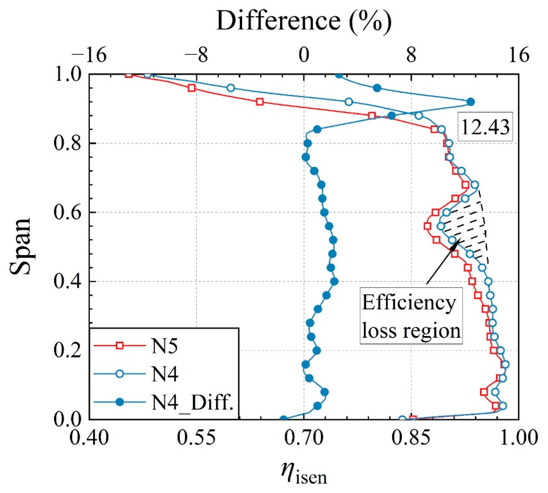
First, by comparing the difference in the spanwise distribution of ηisen under different rotating speeds, the regions to be analyzed were determined. The spanwise distribution of the tandem rotor at N4 and N5 is shown in Figure 11, and the difference is obtained via subtraction between the two. The region near the tip exhibits substantial differences. The maximum difference is located at nearly 90% span, while the difference of other spans is relatively small, which is all within 3%. However, note that massive efficiency loss occurs near 60% span, which has not been observed for a traditional fan or compressor. Thus, this region needs to be analyzed.
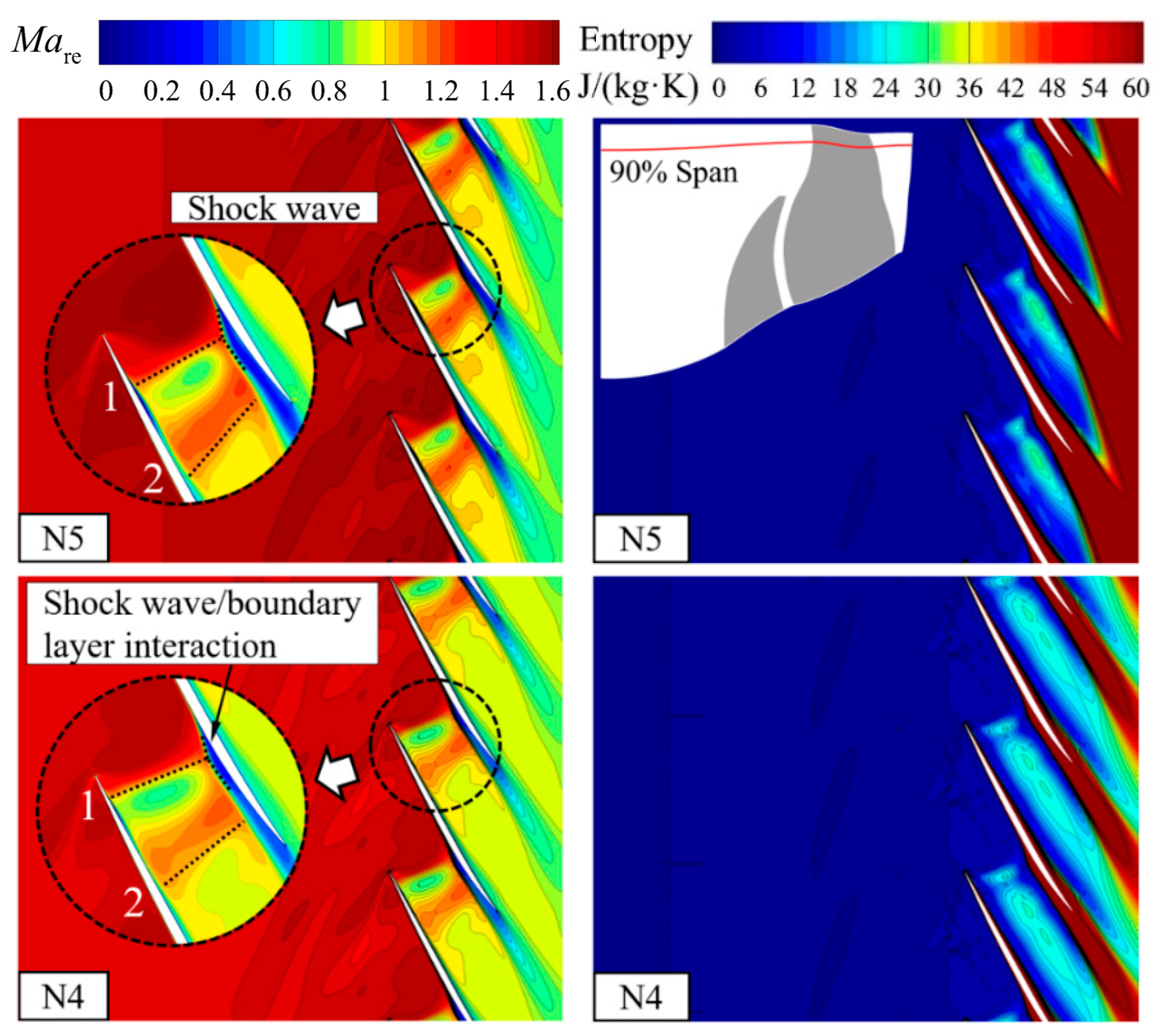
The most direct change to the rotor with an increase in rotating speed is the increase in the tangential velocity, which subsequently increases the relative Mach number (Mare) of the inflow. Therefore, the effects of the shock wave, wake, and leakage flow are all enhanced, which is the source of the sharp increase in losses near the tip region. Figure 12 shows the Mare and entropy distribution of 90% span. The flow features are the same under different speeds, including the two shock waves and the separation caused by the shock wave/boundary layer interaction. The contour shows that the entropy directly caused by the shock wave at N4 is broader than that at N5, but the shock wave intensity is higher under the overspeed condition. In contrast, the boundary layer loss caused by the shock wave is more pronounced under N5, and this loss is the main reason for the reduction in ηisen. As the tandem rotor and stator are aerodynamically matched, the former domain is closer to the choke condition, and the shock wave position approaches the TE streamwise. Moreover, the effect caused by the stronger shock wave is accordingly enhanced, resulting in the thickening of the boundary layer and increased loss. Moreover, Mare at the lower span will increase with the rotating speed, which will generate a shock wave and induce boundary layer thickening or flow separation. Thus, there must be more low-energy fluid, which will migrate radially under the effect of the centrifugal force, accumulate to the tip region, and diffuse downstream, thereby increasing the loss.
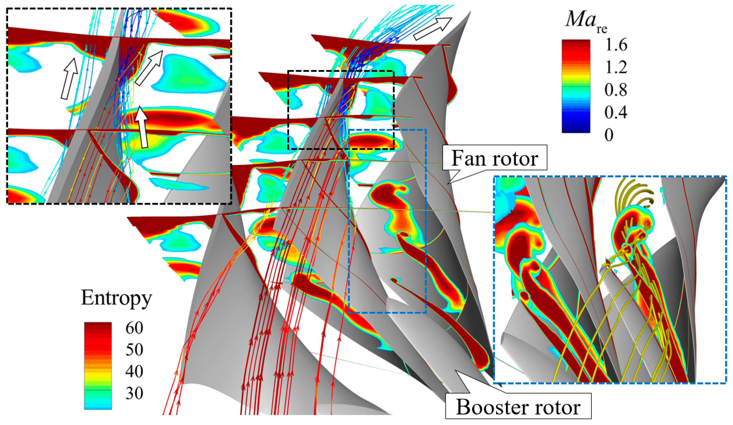
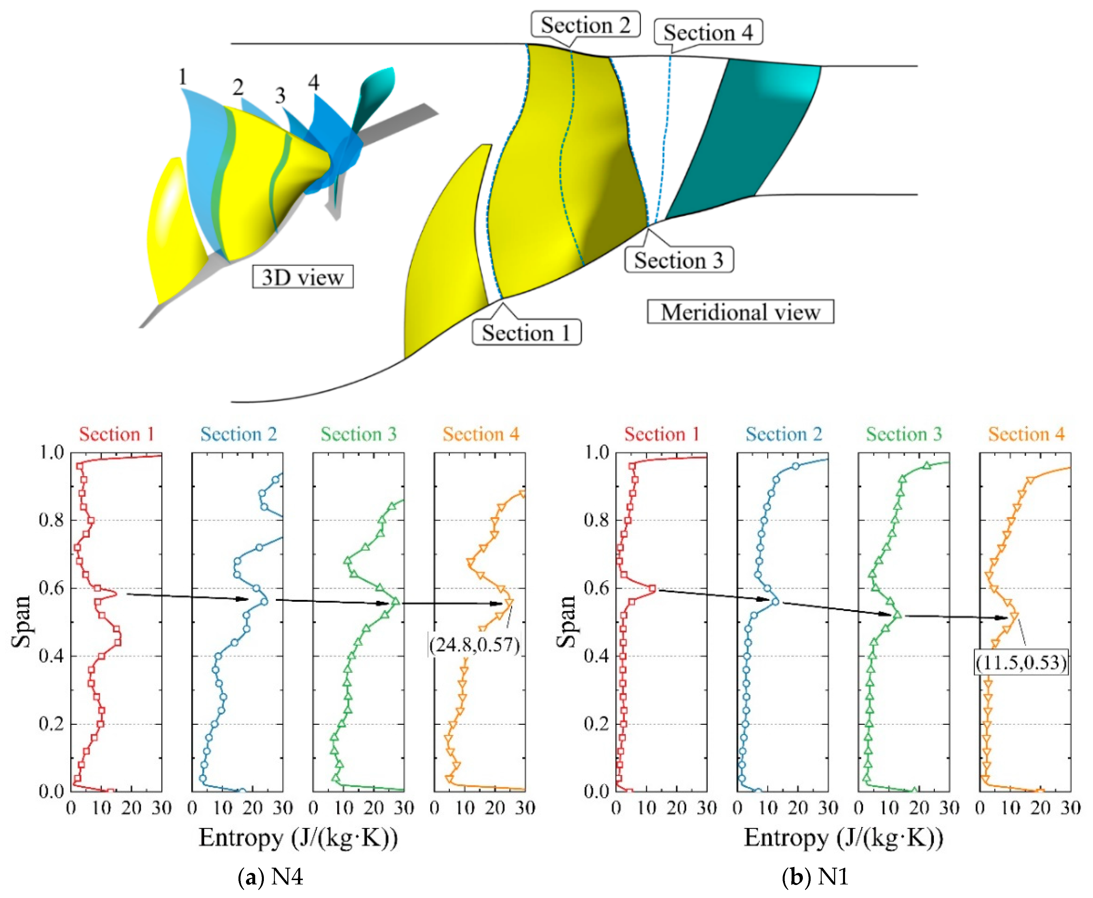
The entropy distribution along the streamwise under the overspeed condition is further demonstrated, and the 3D streamlines colored by Mare are emitted from the high-entropy region. It is confirmed that the streamlines through the high-entropy region of SS are from the radial migration of low-energy fluid, while those of PS are from the tip leakage flow of the adjacent blade and the boundary layer fluid on PS. The commonality of the above flow features is that they will deflect in the counter-rotation direction when entering the uncovered region, thereby forming a high-entropy region in almost the entire circumferential direction. The driving force of the deflection is the Coriolis force. As the rotating speed is determined, the circumferential Coriolis force is mainly determined by the radial velocity. Based on the above analysis, at 90% span, multiple effects of the stronger shock wave/boundary layer interaction, radial migration of a great quantity of low-energy fluid, and Coriolis force cause the reduction of ηisen under the overspeed conditions.
The source of the spanwise efficiency loss also needs to be further explored. Figure 13 displays the entropy distribution along streamwise at the middle-lower span. After the booster rotor, except for the spanwise high-entropy region of the wake, a circumferential high-entropy region is present, but the scope is relatively small. As the airflow diffuses downstream, the intensity of the circumferential high-entropy region does not weaken, and its effect expands in both circumferential and spanwise directions. The streamlines through the high-entropy region are emitted from the booster rotor, which mainly comprises three sources. The first is the leakage vortex driven by the pressure difference between SS and PS at the tip, the second is the radial vortex formed by the radial migration, and the third is the low-energy fluid formed by the boundary layer on the tip of the booster rotor.
Since no shroud restriction is present, low-energy fluids are influenced by the leakage vortex, forming a stronger TV and diffusing downstream. With increasing rotating speed, the tip loading of the booster rotor will increase and the driving force will be strengthened, which will subsequently increase the vortex strength. Therefore, the loss of the shear effect with the surrounding mainstream will also increase. Furthermore, the wakes of the booster and fan rotors will broaden, thereby increasing the loss at the rotor outlet.
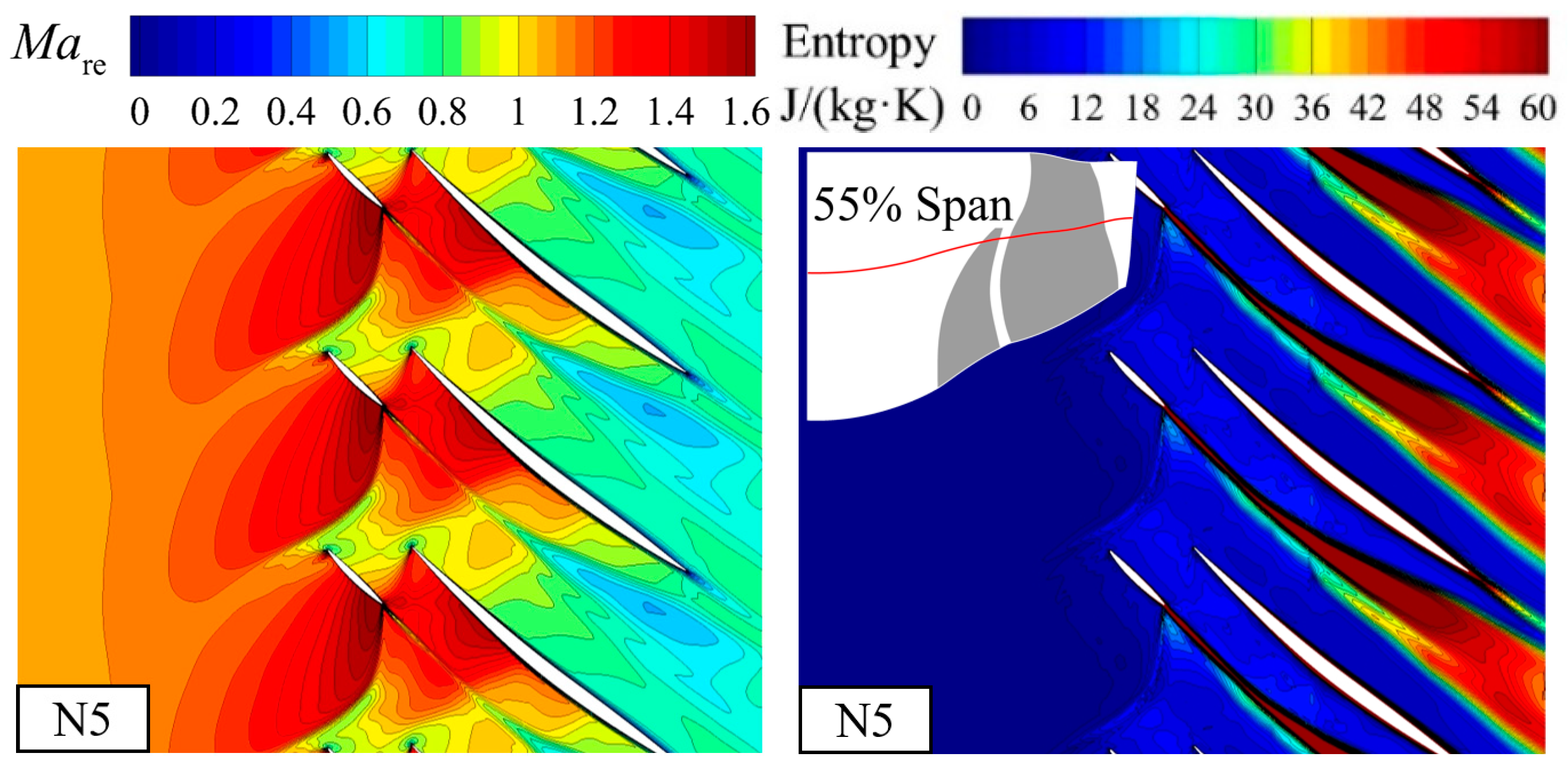
Figure 14 shows the Mare and entropy contour of the tandem rotor at 55% span. The interaction between the booster and fan rotors increases under the overspeed condition. On the one hand, the intensity of the accelerated flow at the gap between the tandem rotors increases, but from the perspective of entropy, no additional loss is observed. In contrast, the enhancement of the shock wave intensity at the LE of the booster rotor increases the loss. On the other hand, the width of the booster rotor wake gradually extends after passing through the shock wave of the fan rotor, denoting the expansion of the high-entropy region. As shown in the figure, the wake widens in the overspeed condition. Therefore, the loss of 55% span is relatively high. In summary, the enhancement in the intensity of TV and wake under the overspeed condition will cause the reduction of ηisen in the middle-lower span.
4.3. Partial Speed Operating Conditions
When the engine is in the ground idle condition, the fan/compressor operates at low speeds. Therefore, studying the flow mechanism of the high-throughflow fan at the partial rotating speed is extremely important. The overall stage aerodynamic performance curve of the fan shows that the peak efficiency of N2 reaches the maximum, and the peak efficiency will decrease when the speed is increased or decreased. Consistent with the overspeed condition analysis, the aerodynamic performance of each domain should be separately considered. Figure 15 displays the characteristic curves of ηisen and Cpt under different rotating speeds, and the PEP of the overall stage is marked. As the rotating speed decreases, the ηisen curve of the rotor gradually shifts to the upper left in the figure and the peak efficiency gradually increases; the minimum Cpt does not apparently change at different speeds, and the curve approximately shifts to the left with decreasing speed. According to the PEP position, the matching point between the tandem rotor and stator gradually shifts away from the choke condition. Therefore, the ηisen curve of the fan stage shows the change trend in Figure 7, while the peak efficiency shows the change trend in Figure 8.
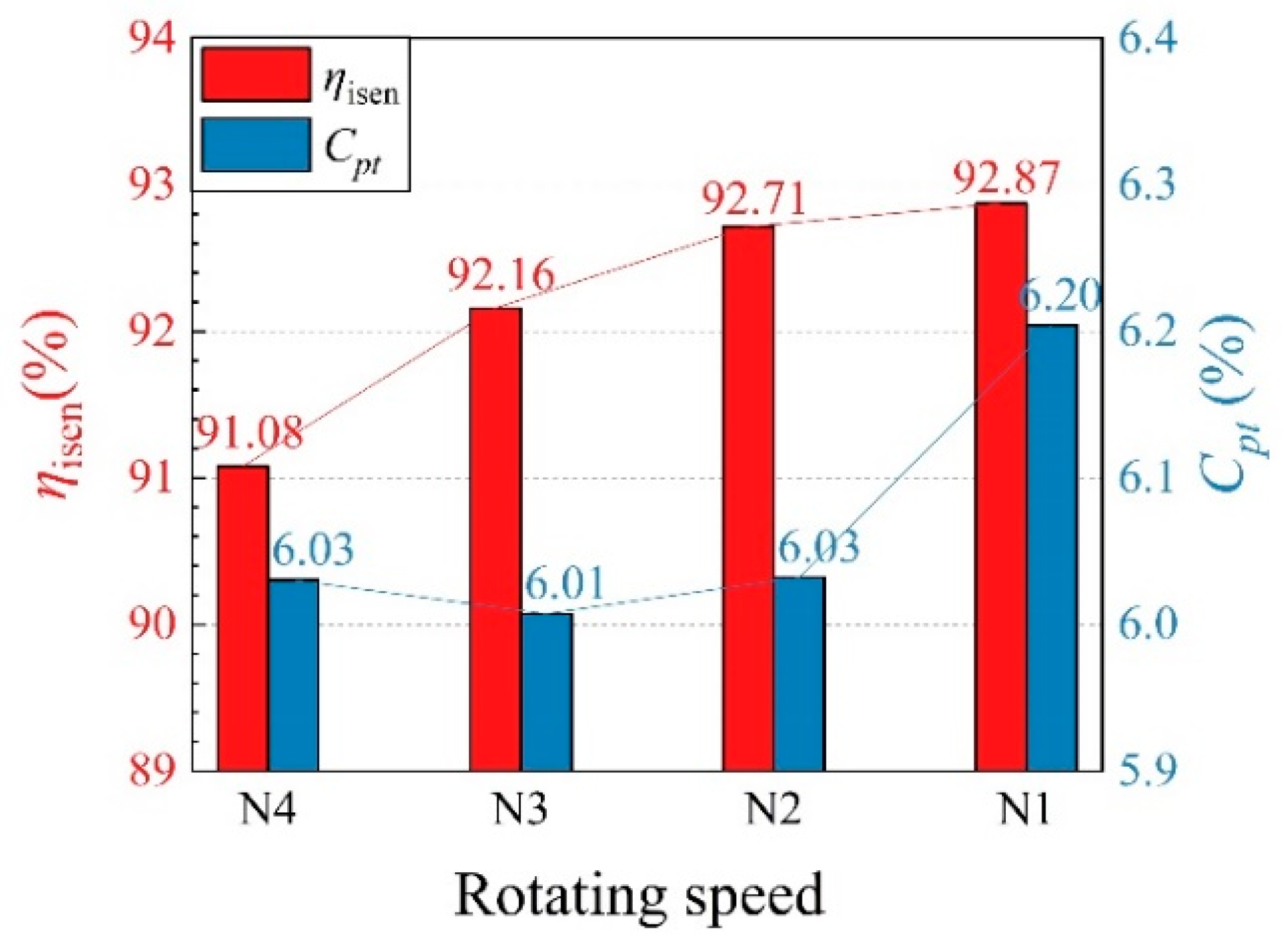
To quantitatively verify this conclusion, the aerodynamic performance of the tandem rotor and stator corresponding to the overall stage PEP were selected and represented by a histogram (Figure 16). The ηisen of the tandem rotor gradually increases, but it reaches a steady state as the speed decreases. The Cpt of the stator does not significantly change with the speed, but it suddenly increases by 0.17% when N2 decreases to N1. Therefore, even if the ηisen of the tandem rotor increases at N1, the peak efficiency of the fan stage still decreases. However, note that the shifting of the matching point caused by the aerodynamic design is the fundamental reason for the decrease, and the loss caused by the stator is not the main reason for determining the aerodynamic performance. Therefore, subsequent analysis will mainly focus on the tandem rotor region.
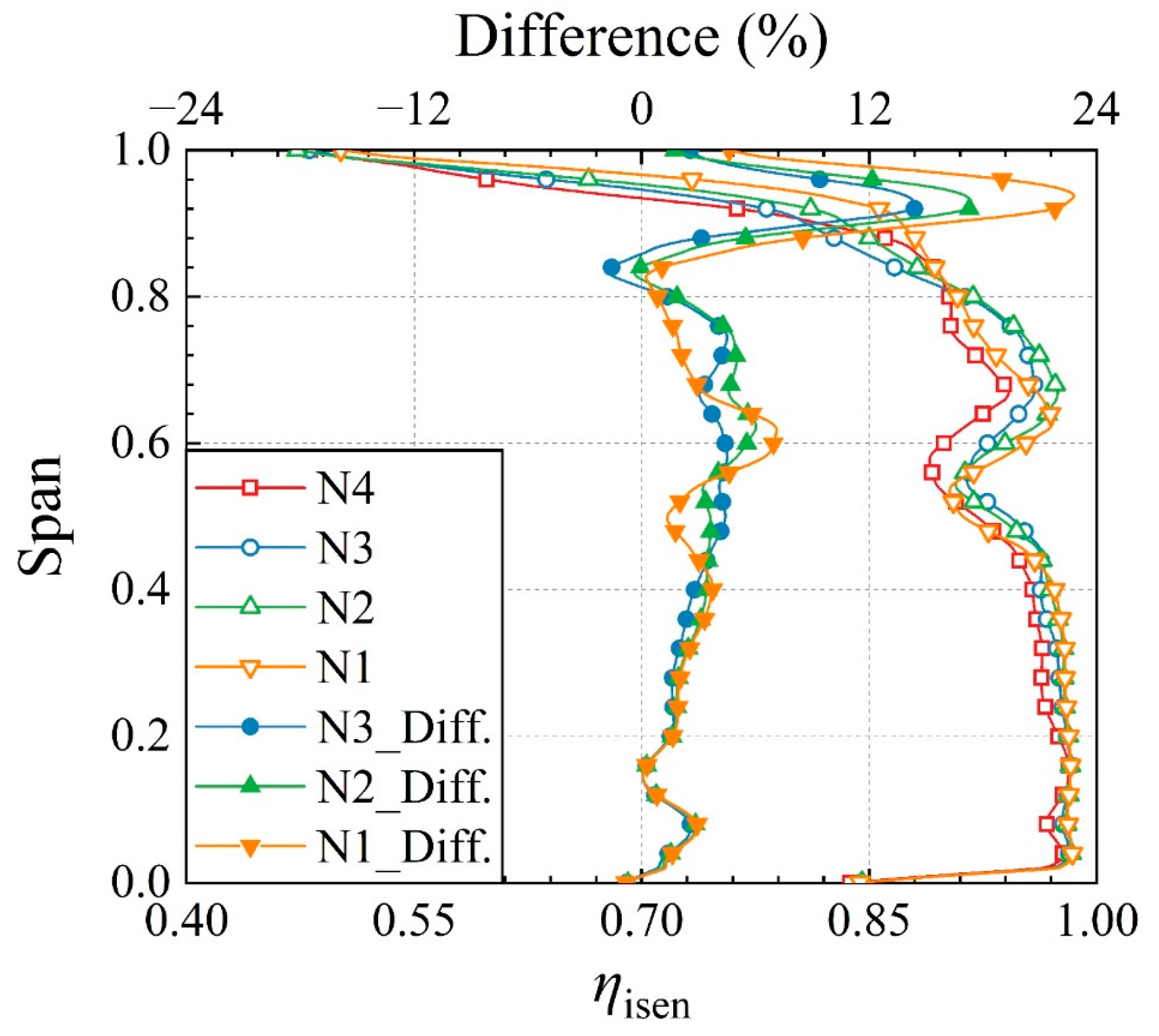
As shown in Figure 17, the ηisen spanwise distribution of the stage interface at different rotating speeds is compared, and the ηisen corresponding to the partial speeds is compared with N4. The region with apparent changes is still near the tip, which exhibits an increment of approximately 24% compared with N4, while the changes at other spans are all within 5%. However, at some of these spans, the change trend of ηisen is difficult to interpret. For example, at 75% span, ηisen suddenly decreases at N1, while other speeds do not exhibit such a phenomenon; for example, the reduction of ηisen also occurs at 50% span. Therefore, the flow field needs to be further combined for judgment and analysis.
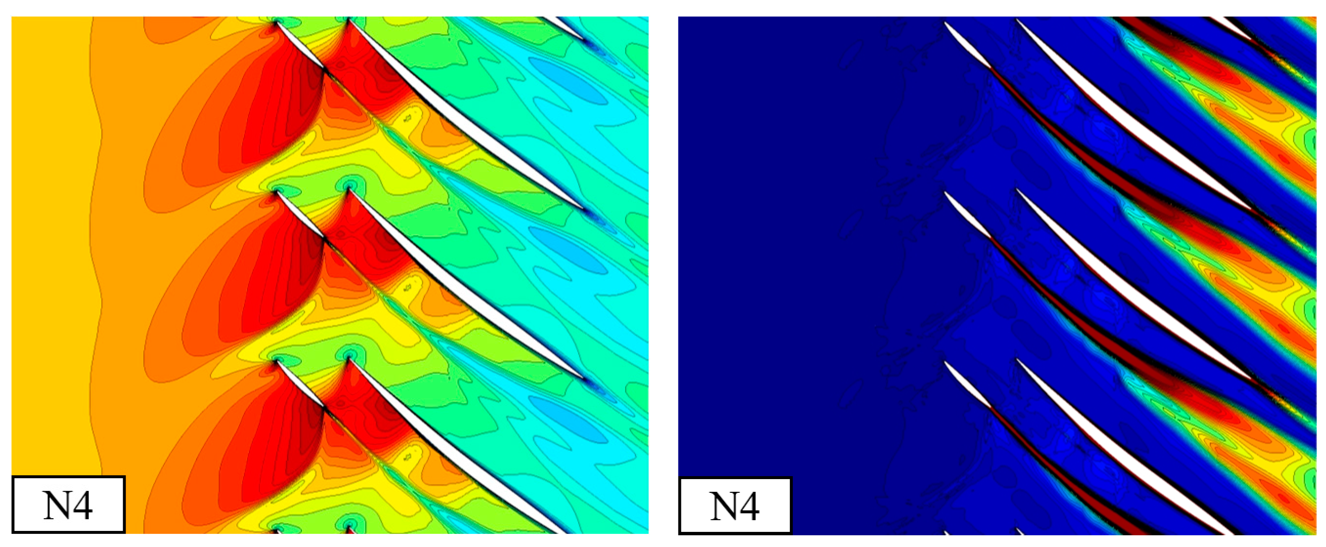
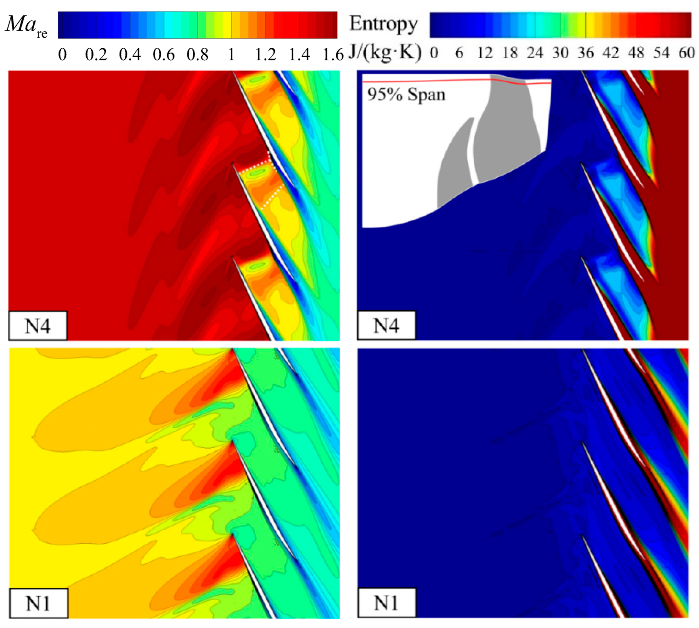
The Mare and entropy contour at 95% span of the tandem rotor at N4 and N1 are demonstrated in Figure 18. Clearly, as the rotating speed decreases, Mare will transition from supersonic to transonic and gradually break away from the choke condition. Moreover, the strength of the LE shock wave weakens, and the shock wave and boundary layer loss are greatly reduced. On the other hand, the reduction in Mare leads to decreased loading near the tip, thereby weakening the leakage strength and further reducing the loss. Therefore, the combined reasons for these two aspects result in the change trend of ηisen.
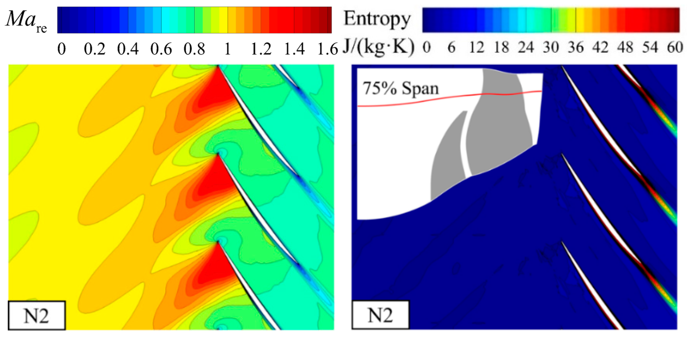
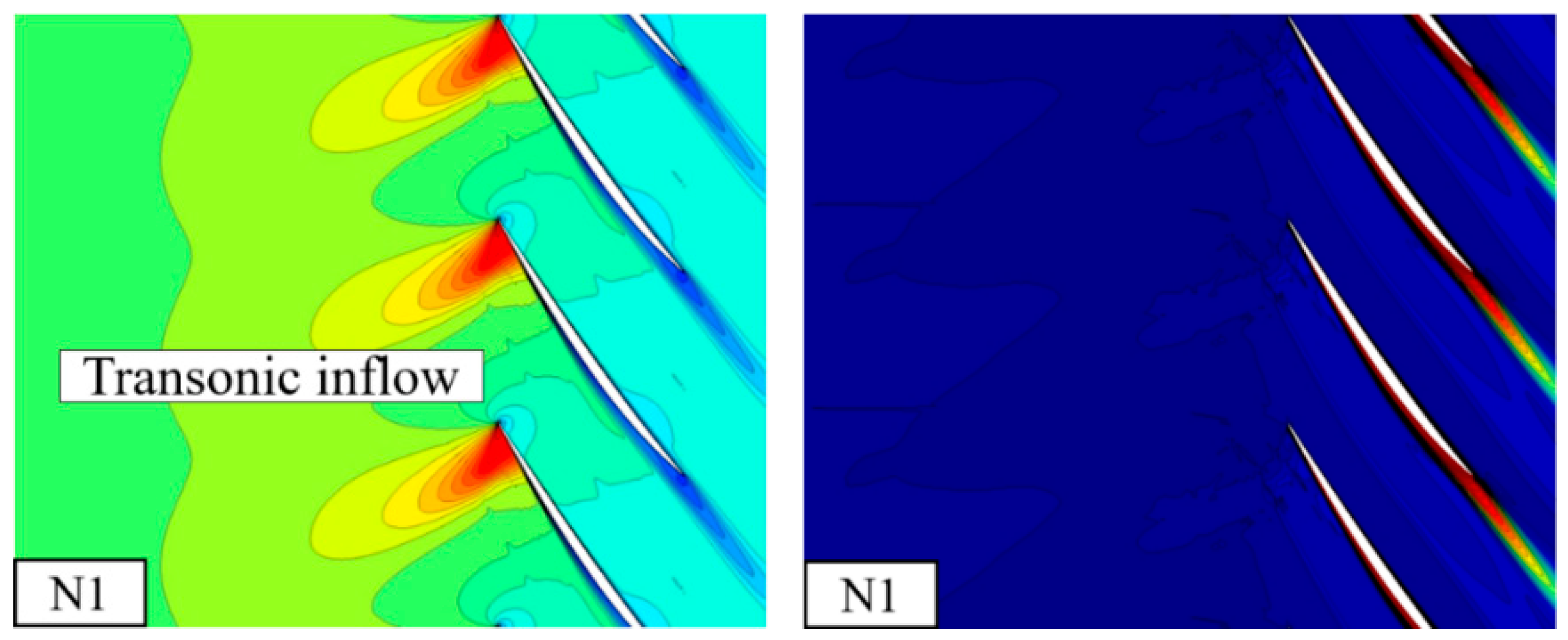
Similarly, the change trend of ηisen at 75% span from N4 to N2 is relatively regular, which is caused by the reduction of the inflow Mare. However, if it is further reduced to N1, the drop in Mare will increase the loss. Figure 19 displays the Mare and entropy distribution at 75% span of N1 and N2. From the flow field, the inflow Mare decreases, which is consistent with the change trend of 95% span. However, at N1, the scope of the wake is broader than that at N2. At N1, no strong passage shock wave is present, and the scale of the boundary layer or separation caused by the shock wave is bound to be weaker. Nevertheless, the boundary layer rapidly thickens streamwise. Such a phenomenon occurs due to the excessively low inflow velocity. The ability to resist the adverse pressure gradient is restricted, and it is more likely to form the boundary layer accumulation. Additionally, the shock wave position is closer to LE, and the airflow is reduced to subsonic through the shock wave with insufficient acceleration. Therefore, a broader wake forms at N1 compared to that at N2.
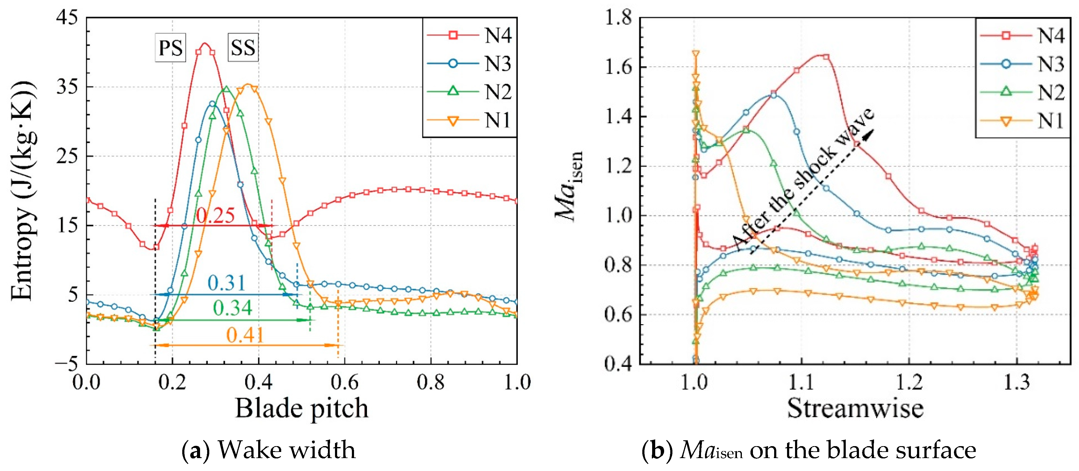
To quantitatively describe the wake extent and the evolutionary process of the near-wall velocity, the entropy distribution in the circumferential direction at the rotor outlet and isentropic Mach number (Maisen) distribution on the blade surface at different speeds are further obtained, as shown in Figure 20. The figure shows that at different speeds, the beginning positions of the PS branch for the wake are basically the same, while those of the SS branch are quite different. As the rotating speed decreased, the wake width became broader. At N1, the wake occupied about 40% of the blade passage. Compared with N2 and N3, the wake and high loss region significantly expanded at N1. At partial rotating speeds, there is little difference in entropy in the region not affected by the wake. Therefore, the source of the ηisen change trend at 75% span is identified as the change in the wake width. From the Maisen distribution, after the airflow passes through the shock wave near the wall, Maisen is subsonic at N1, and the deceleration and pressurization processes begin from about 20% chord length. Therefore, the growth rate of the boundary layer thickness increases, which can be confirmed by the above speculation.
The ηisen at 50% span under N1 suddenly decreases. According to the previous analysis of the ηisen loss region, ηisen is bound to be affected by TV. Therefore, the spanwise distribution of entropy is plotted further along streamwise at N4 and N1 in Figure 21. The beginning position of TV is nearly at the same span under different speeds. As the speed decreases, the span of TV at the rotor outlet gradually decreases, corresponding to the ηisen distribution of the tandem rotor. This flow phenomenon is considered to be related to the leakage flow of the booster rotor. When the rotating speed decreases, the loading at the booster rotor tip inevitably decreases, leading to a reduction in the pressure difference and thereby reducing the tangential velocity of the leakage flow. Therefore, the inertial force generated by the tangential velocity of the airflow is insufficient for enabling the TV to migrate higher and needs to be balanced with the radial adverse pressure gradient, resulting in a gradual reduction in its radial position at the rotor outlet.
To prove the above speculation about the migration trend of TV, the cylindrical coordinate form of the Navier–Stokes equation is employed. This paper focuses on the radial migration of TV; thus, the radial component equation is finally selected for further analysis and discussion, and it is expressed as follows:
where w represents the relative velocity, the subscripts r, θ, and z represent the radial, circumferential, and axial directions, respectively, ω represents the angular velocity, and ρ represents the density. The three terms on the left side of the above expression are acceleration terms. On the right side, the first term is the adverse pressure gradient term, the second term is the centrifugal force term, the third term is the Coriolis force term, the fourth term stems from the cylindrical coordinate system, and the fifth term is the viscosity term. Furthermore, the second and third terms on the right side are inertial force. In terms of the expression, the fourth term can be equivalent to the centrifugal force. Therefore, the second to the fourth terms are named as the equivalent inertial term. Additionally, the equivalent inertial term can be rewritten as
where u represents the local tangential velocity. Based on the expression, the equivalent inertia term must be greater than 0 to resist the radial pressure gradient and move the fluid radially upward. Figure 22 displays the distribution of the adverse pressure gradient and equivalent inertial force streamwise of the tandem rotor at N1. Additionally, the entropy isoline in the figure denotes the TV profile. The upper half of TV presents a positive pressure gradient and a higher equivalent inertial force, while the lower half presents an adverse pressure gradient and a lower equivalent inertial force. Therefore, the pressure gradient and equivalent inertial force are highly correlated. Since TV is driven by the pressure difference, the upper half of TV exhibits a larger relative circumferential velocity, while the lower half exhibits a smaller one. Therefore, after subtracting and squaring the relative circumferential velocity with the tangential velocity near the TV region, the upper and lower half regions are clearly divided. The figure also shows that the vortex core is roughly located at the positive pressure gradient region. Moreover, the left side of the expression is basically determined by the positive pressure gradient and equivalent inertial force (compared to other terms on the right side, the order of the viscous term in the main flow region is lower; thus, it can be ignored). As the rotating speed decreases, the intensity of the equivalent inertial force at the vortex core gradually decreases; therefore, the radial position of TV changes to downward, verifying the previous speculation.
Figure 23 demonstrates the Mare and entropy contour at 50% span of the tandem rotor for N4 and N1. As the rotating speed decreases to N1, no shock wave forms in the blade passage at 50% span, the accelerated flow in the nozzle weakens, and no additional loss occurs in the mainstream. The difference between the two cases is mainly in the wake width, and the wake loss at N4 is higher than that at N1. Furthermore, a large-scale high-entropy region (white dotted circle) near the pressure surface (PS) of the fan rotor exists at N1, representing TV, which confirms the analysis of the radial migration trend of TV in this paper.
4.4. Gain of Choke Mass Flow at Different Rotating Speeds
A booster rotor is introduced into the fan stage to mainly improve the flow capacity near the hub. Table 3 shows that, with N3 as the dividing line, when the speed exceeds it, the tandem fan stage can improve , which is the flow capacity. However, the growth rate under the overspeed condition slows down. When the rotating speed drops below N3, the introduction of the booster rotor will have a negative effect. Therefore, the aerodynamic advantages of the high-throughflow fan can be gradually demonstrated at high speeds. This subsection combines aerodynamic theory with flow field analysis to clarify the change trend of the growth rate for , fundamentally explain the problem, and reveal its internal flow mechanism.
In aerodynamics, it has been indicated that under the condition of subsonic inflow with a certain total temperature and total pressure, once the critical section (Ma = 1) of the Laval nozzle appears, it will reach the choke condition and cannot be increased by further reducing the back pressure. Under the choke condition, the airflow generally has a low total pressure loss before passing through the throat in the stator. In other words, the π of the rotor can approximately measure the inflow compression intensity before the throat. Figure 24 displays the relative change in the π and of the tandem rotor compared to that of the fan rotor inside the baseline fan stage under the choke condition. The gain of π is always positive, while that of is negative below N3. Such a phenomenon occurs due to the introduction of the booster rotor, which causes excessively high loading near the stator hub. To suppress the flow deterioration, the hub profile of the baseline fan stage is modified, that is, the slope angle of the hub profile in the stator domain is lifted to 15° to obtain the hub profile of the new concept tandem fan stage. Therefore, the aerodynamic throat area of the overall stage is greatly reduced. The gain of π shows a quadratic trend with increasing speed. At N4 and partial speed conditions, the gain of is positively correlated to that of π. When the speed is increases to the overspeed condition, the gain of is abnormal. Therefore, it can be inferred that the throat area contributed to the generation of such a trend.
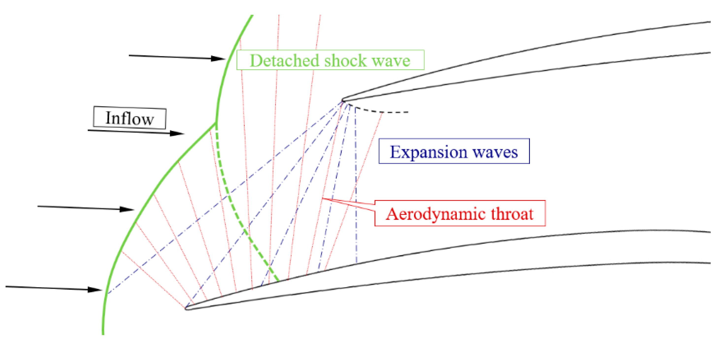
The booster rotor was introduced to increase the core pressure ratio. Since the tangential velocity near the hub of the rotor domain is insufficient, the tandem rotor implants energy into the airflow by increasing the flow turning, thereby enhancing the compression intensity of the airflow before the aerodynamic throat. During the aerodynamic design, to improve the compression capability near the hub, the total camber angle of the tandem rotor (53°) is much larger than that of the baseline fan rotor (33°). Therefore, the reaction near the tandem rotor hub is reduced compared to that at the baseline fan rotor, and the airflow velocity at the stator inlet accordingly increases. The stator inflow can even reach the supersonic condition at N4 and N5. Therefore, a great negative incidence under choke condition was designed to avoid premature corner stall. In contrast to the subsonic inflow in the Laval nozzle, the determination of the aerodynamic throat position under such inflow condition is rarely studied; thus, physical modeling analysis is required. Figure 25 presents a schematic to analyze the aerodynamic throat position. The green lines in the figure represent the detached shock wave, and the red and blue dashed lines represent the expansion waves emitted by the suction surface (SS) and PS, respectively. An expansion wave from PS will first intersect with the LE of the stator. Although the disturbance after the expansion wave cannot affect the flow field in front of the blade, the disturbance from SS can still be transmitted upstream. Therefore, when an expansion wave emitted from SS intersects the LE of the adjacent blade, the flow field in the channel will no longer affect the upstream. Then, the position of the aerodynamic throat can be determined. However, the two expansion waves from SS and PS will intersect with a high probability. Thus, the lower half of the throat profile is determined by the expansion wave from SS, while the upper half is determined by the expansion wave from PS.
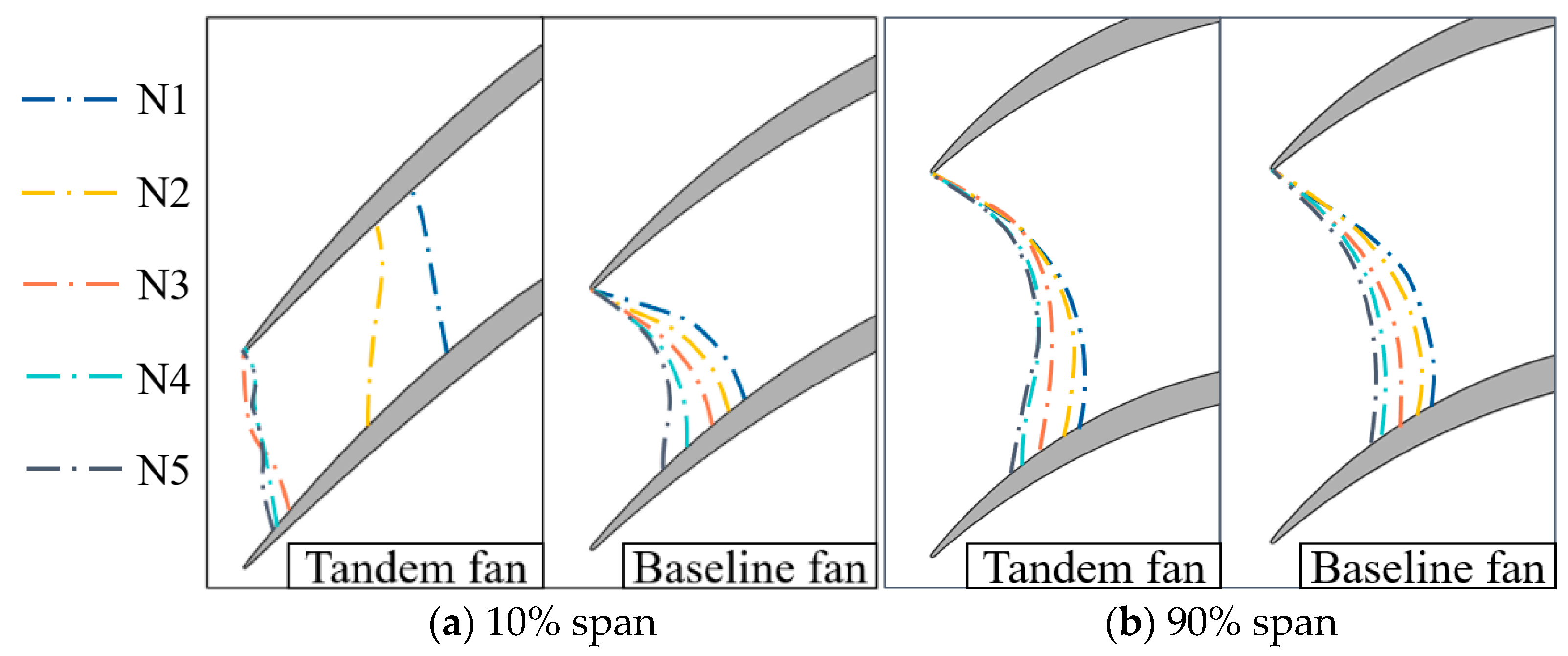
Figure 26 displays the aerodynamic throat distribution near the hub and tip under the choke condition for the high-throughflow fan and baseline conventional fan, where the throat positions at different rotating speeds are denoted with dashed lines. When the rotating speed under the partial design speed condition is increased, the throat position of the high-throughflow fan stator and the baseline stator move upstream, signifying an increase in the throat area. Note that when N3 rises to N4, the throat position at the hub does not apparently change. However, since the Mach number of the supersonic inflow at the throat is greater than one, the gain of at N4 rapidly increases. However, as N4 increases to N5, the throat position of the high-throughflow fan does not significantly change either at the hub or tip. Compared to the increase of the throat area for the baseline, the throat area of the high-throughflow fan nearly does not change under the overspeed condition, denoting a relative reduction of the throat area. Although the change of the rotor pressure ratio still increases at this time, the growth rate of the gain of will generally be abnormal.
5. Conclusions
In this paper, the numerical simulation method verified by the experimental results was employed to study the aerodynamic performance trends of the high-throughflow fan at N1, N2, N3, N4, and N5. The change rules of several complicated flow features were summarized, thereby establishing a relation between the aerodynamic performance and flow structure, deepening the understanding of the internal flow mechanism of the new concept fan stage, and obtaining the following important conclusions:
(1) The π of the high-throughflow fan gradually increases at different rotating speeds, and the gain demonstrates a quadratic growth rate compared with a conventional baseline fan. The peak efficiency reaches the maximum at N2, which is mainly due to the shifting of the matching point between the tandem rotor and stator.
(2) The main reasons for the reduction of the peak efficiency under the overspeed condition were discussed. The enhancement of the boundary layer separation and radial migration of the low-energy fluid caused by shock waves is the reason for the decrease in the ηisen at 90% span, while the reduction in ηisen at the lower span is due to the enhanced TV and wake.
(3) The change of the ηisen spanwise distribution for the tandem rotor at the partial rotating speed was studied. The reason for the ηisen change trend at 95% span is consistent with the overspeed condition. However, the inflow Mare at 75% span shows that either a too high or too low value can have a negative effect. The ηisen change is mainly dominated by TV at 50% span, and the equivalent inertial force is the decisive factor of its radial migration trend.
(4) When the rotating speed exceeds N3, will produce a positive gain. The change trend of the gain for the at N4 is more consistent with π, but it is abnormal under the overspeed condition. Generally, a high-throughflow fan can fully demonstrate the aerodynamic advantages only at high rotating speeds.
(5) Based on the lack of previous studies, a physical model was established to discuss the method of determining the throat position under conditions of supersonic inflow with a large negative incidence. It was determined that the abnormal gain of under the overspeed condition stemmed from the relative deficit of throat area.
Future research can be progressed in two aspects. The effect of the relative position of the tandem rotor on the aerodynamic performance and the internal flow mechanism should be discussed under different rotating speed. The structural design and test verification of the new concept tandem fan stage should be completed to promote its practical application.
Author Contributions
Conceptualization, S.Z. and X.L.; methodology, C.Z.; software, X.L.; validation, C.Z., S.Z. and X.L.; formal analysis, C.Z.; investigation, C.Z., S.Z. and X.L.; resources, S.Z. and X.L.; data curation, C.Z.; writing—original draft preparation, C.Z.; writing—review and editing, C.Z., S.Z. and X.L.; visualization, C.Z.; supervision, S.Z. and X.L.; project administration, S.Z. and X.L.; funding acquisition, S.Z. and X.L. All authors have read and agreed to the published version of the manuscript.
Funding
This work was supported by the Special Research Project of Chinese Civil Aircraft under Grant No. MJZ-2016-D-25 and National Science and Technology Major Project under Grant No. 2019-II-0004-0024.
Data Availability Statement
Not applicable.
Conflicts of Interest
The authors declare that they have no known competing financial interest or personal relationships that could have appeared to influence the work reported in this paper.
Nomenclature
| mass flow | |
| c | absolute velocity |
| Cpt | total pressure loss coefficient |
| e | relative measurement error |
| Ma | Mach number |
| p | pressure |
| u | local tangential velocity |
| w | relative velocity |
| N1, N2, N3, N4, N5 | 70%, 80%, 90%, 100%, 105% design speed |
Abbreviations
| 3D | three dimensional |
| LE | leading edge |
| PEP | peak efficiency point |
| PS | pressure surface |
| SS | suction surface |
| TE | trailing edge |
| TV | tip vortex |
Greek Symbols
| η | isentropic efficiency |
| π | total pressure ratio |
| ρ | density |
| ω | angular velocity |
Superscripts and Subscripts
| * | total |
| 0 | stage inlet |
| 1 | booster rotor outlet |
| 2 | stage interface |
| 3 | stage outlet |
| choke | choke condition |
| design | design condition |
| isen | isentropic |
| r | radial direction |
| re | relative |
| z | axial direction |
| θ | circumferential direction |
References
- Goto, S.; Kodama, H. Design of Advanced Transonic Fan Rotor. In Proceedings of the Asian Joint Conference on Propulsion and Power, Kitakyushu, Japan, 27–29 January 2005. AJCPP2005 D2-2. [Google Scholar]
- Murooka, T.; Goto, S.; Mizuta, I.; Kodama, H. New Concept Design and Development of an Advanced Transonic Fan Rotor. In Proceedings of the International Gas Turbine Congress, Tokyo, Japan, 2–7 December 2007. IGTC ABS-168. [Google Scholar]
- Zhou, C.; Li, Z.; Huang, S.; Han, G.; Lu, X.; Zhao, S.; Zhu, J. Numerical investigation on the aerodynamic performance and flow mechanism of a fan with a partial-height booster rotor. Aerosp. Sci. Technol. 2020, 109, 106411. [Google Scholar] [CrossRef]
- Zhou, C.; Zhao, S.; Yang, C.; Han, G.; Lu, X. The matching characteristics and flow mechanisms of partial-height booster rotor and fan rotor for a high-throughflow fan. Proc. Inst. Mech. Eng. Part C J. Mech. Eng. Sci. 2022. [CrossRef]
- Li, Z.; Zhao, S.; Lu, X.; Han, G.; Yang, C.; Zhu, J. Inducer/Exducer Matching Characteristics inside Tandem Impellers of a Highly Loaded Centrifugal Compressor. J. Therm. Sci. 2020, 29, 928–944. [Google Scholar] [CrossRef]
- Li, Z.; Lu, X.; Han, G.; Huang, E.; Yang, C.; Zhu, J. Numerical and experimental investigation of flow mechanism and application of tandem-impeller for centrifugal compressor. Aerosp. Sci. Technol. 2020, 100, 105819. [Google Scholar] [CrossRef]
- Li, Z.; Han, G.; Lu, X.; Huang, E.; Zhao, S. Improving the operating range using a centrifugal compressor with a tandem impeller. Aerosp. Sci. Technol. 2019, 96, 105548. [Google Scholar] [CrossRef]
- Burger, G.D.; Keenan, M.J. Single-Stage Evaluation of Highly-Loaded High-Mach-Number Compressor Stages, Part 3: Data and Performance Tandem Rotor; CR-72772; NASA NTRS: Washington, DC, USA, 1971.
- Brent, J.A.; Clemmons, D.R. Single-Stage Experimental Evaluation of Tandem-Airfoil Rotor and Stator Blading for Compressors, Part 8: Final Report; CR-134713; NASA NTRS: Washington, DC, USA, 1974.
- Bammert, K.; Staude, R. Optimization for Rotor Blades of Tandem Design for Axial Flow Compressors. J. Eng. Power 1980, 102, 369–375. [Google Scholar] [CrossRef]
- Bammert, K.; Beelte, H. Investigations of an Axial Flow Compressor with Tandem Cascades. J. Eng. Power 1980, 102, 971–977. [Google Scholar] [CrossRef]
- Bammert, K.; Staude, R. New features in the design of axial-flow compressors with tandem blades. In Proceedings of the ASME 1981 International Gas Turbine Conference and Products Show, Houston, TX, USA, 9–12 March 1981. ASME Paper 81-GT-113. [Google Scholar] [CrossRef] [Green Version]
- McGlumphy, J.; Ng, W.-F.; Wellborn, S.R.; Kempf, S. 3D Numerical Investigation of Tandem Airfoils for a Core Compressor Rotor. J. Turbomach. 2010, 132, 031009. [Google Scholar] [CrossRef]
- Liu, B.; Zhang, C.; An, G.; Fu, D.; Yu, X. Using tandem blades to break loading limit of highly loaded axial compressors. Chin. J. Aeronaut. 2022, 35, 165–175. [Google Scholar] [CrossRef]
- Kumar, A.; Pradeep, A. Design and off-design behavior of a tandem rotor stage. Proc. Inst. Mech. Eng. Part G J. Aerosp. Eng. 2019, 234, 927–942. [Google Scholar] [CrossRef]
- Kumar, A.; Pradeep, A. Experimental investigation of tandem rotor under clean and radially distorted inflows. Propuls. Power Res. 2021, 10, 247–261. [Google Scholar] [CrossRef]
- Kumar, A.; Chhugani, H.; More, S.; Pradeep, A.M. Effect of Differential Tip Clearance on the Performance of a Tandem Rotor. J. Turbomach. 2022, 144, 1–30. [Google Scholar] [CrossRef]
- Urasek, D.C.; Janetzke, D.C. Performance of Tandem-Bladed Transonic Compressor Rotor with Tip Speed of 1375 Feet per Second; TM X-2484; NASA NTRS: Washington, DC, USA, 1972.
- Hasegawa, H.; Matsuoka, A.; Suga, S. Development of highly loaded fan with tandem cascade. In Proceedings of the 41st Aerospace Sciences Meeting and Exhibit, Reno, Nevada, 6–9 January 2003. AIAA-1065. [Google Scholar] [CrossRef]
- Sakai, Y.; Matsuoka, A.; Suga, S.; Hashimoto, K. Design and test of transonic compressor rotor with tandem cascade. In Proceedings of the International Gas Turbine Congress, IGTC TS-108, Tokyo, Japan, 2–7 November 2003. [Google Scholar]
- Mohsen, M.; Owis, F.M.; Hashim, A.A. The impact of tandem rotor blades on the performance of transonic axial compressors. Aerosp. Sci. Technol. 2017, 67, 237–248. [Google Scholar] [CrossRef]
- Song, Z.; Liu, B.; Zhang, P.; Mao, X. Analysis of Optimization of Lean and Sweep Influence on Highly Loaded Transonic Tandem Rotor. J. Propuls. Technol. 2018, 39, 23–32. [Google Scholar] [CrossRef]
- Qian, Y.; Li, Z.; Lu, Y.; Li, Q. Flow Mechanics in Tandem Rotors. In Proceedings of the ASME Turbo Expo 2012: Turbine Technical Conference and Exposition, Copenhagen, Denmark, 11–15 June 2012. ASME Paper, GT-69665. [Google Scholar] [CrossRef]
- Qian, Y.; Li, Q.; Lu, Y. Effect of tip leakage flow and wake interactions on off-design point performance of tandem rotor. J. Aerosp. Power 2013, 28, 1350–1356. [Google Scholar] [CrossRef]
- Han, L.; Yuan, W.; Wang, Y. Influence of tip leakage flow and ejection on stall mechanism in a transonic tandem rotor. Aerosp. Sci. Technol. 2018, 77, 499–509. [Google Scholar] [CrossRef]
Figure 1.
3D and meridian surface diagram of the baseline fan.

Figure 2.
Schematic of the key design parameters inside the tandem rotor.

Figure 3.
3D and meridian surface diagram of the high-throughflow fan.

Figure 4.
Grid independence study.

Figure 5.
The physical display of the test rig and fan stage details.

Figure 6.
Comparison between the numerical simulation and experimental results of the baseline fan stage.
Figure 6.
Comparison between the numerical simulation and experimental results of the baseline fan stage.

Figure 7.
Aerodynamic performance of the high-throughflow fan stage at different rotating speeds.

Figure 8.
Relative change trend of , π, and ηisen for the high-throughflow fan stage under different rotating speeds.
Figure 8.
Relative change trend of , π, and ηisen for the high-throughflow fan stage under different rotating speeds.

Figure 9.
The aerodynamic performance of various components at N4 and N5.

Figure 10.
Aerodynamic performance of the tandem rotor and stator at the PEP of N4 and N5.

Figure 11.
Spanwise distribution of ηisen at the stage interface of N4 and N5.

Figure 12.
Mare and entropy contour at 90% span of the tandem rotor.

Figure 13.
Streamwise entropy contour and 3D streamlines of the tandem rotor at N5.

Figure 14.
Mare and entropy contour at 55% span of the tandem rotor.


Figure 15.
Aerodynamic performance of various components at N1, N2, N3, and N4.

Figure 16.
Aerodynamic performance of the tandem rotor and stator at PEP of N1, N2, N3, and N4.

Figure 17.
Spanwise distribution of ηisen at the stage interface of N1, N2, N3, and N4.

Figure 18.
Mare and entropy contour at 95% span of the tandem rotor.

Figure 19.
Mare and entropy contour at 75% span of the tandem rotor.


Figure 20.
Circumferential entropy and Maisen at 75% span of the tandem rotor.

Figure 21.
Spanwise distribution of the entropy at N4 and N1 of the tandem rotor.

Figure 22.
Streamwise distribution of the equivalent inertial force and adverse pressure gradient at N1.
Figure 22.
Streamwise distribution of the equivalent inertial force and adverse pressure gradient at N1.

Figure 23.
Mare and entropy contour at 50% span of the tandem rotor.

Figure 24.
Gain of π and at different rotating speeds.

Figure 25.
Schematic of the aerodynamic throat under a low supersonic inflow with a large negative incidence.
Figure 25.
Schematic of the aerodynamic throat under a low supersonic inflow with a large negative incidence.

Figure 26.
Aerodynamic throat position of the tandem and baseline fans at different rotating speeds.
Figure 26.
Aerodynamic throat position of the tandem and baseline fans at different rotating speeds.


Table 1.
Key geometric and aerodynamic parameters of the baseline fan.
| Design Parameter | Value |
|---|---|
| 34.9 (kg/s) | |
| π | 1.7 |
| Number of blades | 18–43 |
| Hub-to-tip ratio at inlet | 0.32 |
| Rotating speed | 18,278 rpm. |
Table 2.
Key geometric and aerodynamic parameters of the high-throughflow fan.
| Design Parameter | Value |
|---|---|
| Choke mass flow () | 36.3 (kg/s) |
| Tip span of the booster rotor | 60% |
| Number of blades | 18–18–37 |
| Rotating speed | 18,278 rpm. |
| PP | 40% |
| AO | 15% |
Table 3.
Gain of for the high-throughflow fan.
| Rotating Speed | High-Throughflow Fan | Baseline Fan | Gain (%) |
|---|---|---|---|
| N1 | 0.757 | 0.772 | −1.90 |
| N2 | 0.847 | 0.861 | −1.60 |
| N3 | 0.945 | 0.945 | 0.02 |
| N4 | 1.038 | 1.002 | 3.52 |
| N5 | 1.063 | 1.026 | 3.68 |
Publisher’s Note: MDPI stays neutral with regard to jurisdictional claims in published maps and institutional affiliations. |
© 2022 by the authors. Licensee MDPI, Basel, Switzerland. This article is an open access article distributed under the terms and conditions of the Creative Commons Attribution (CC BY) license (https://creativecommons.org/licenses/by/4.0/).
Share and Cite
MDPI and ACS Style
Zhou, C.; Zhao, S.; Lu, X. Flow Mechanism of a New Concept Transonic Tandem Fan Stage under the Design and Off-Design Conditions. Aerospace 2022, 9, 686. https://doi.org/10.3390/aerospace9110686
AMA Style
Zhou C, Zhao S, Lu X. Flow Mechanism of a New Concept Transonic Tandem Fan Stage under the Design and Off-Design Conditions. Aerospace. 2022; 9(11):686. https://doi.org/10.3390/aerospace9110686
Chicago/Turabian StyleZhou, Chuangxin, Shengfeng Zhao, and Xingen Lu. 2022. "Flow Mechanism of a New Concept Transonic Tandem Fan Stage under the Design and Off-Design Conditions" Aerospace 9, no. 11: 686. https://doi.org/10.3390/aerospace9110686
Note that from the first issue of 2016, this journal uses article numbers instead of page numbers. See further details here.