Article

Development of a Novel Deployable Solar Panel and Mechanism for 6U CubeSat of STEP Cube Lab-II

1
Space Technology Synthesis Laboratory, Department of Smart Vehicle System Engineering, Chosun University, 309, Pilmun-daero, Dong-gu, Gwangju 61452, Korea
2
Soletop Co. Ltd., 409 Expo-ro, Yuseong-gu, Daejeon 34051, Korea
*
Author to whom correspondence should be addressed.
Aerospace 2021, 8(3), 64; https://doi.org/10.3390/aerospace8030064
Submission received: 5 February 2021 / Revised: 27 February 2021 / Accepted: 1 March 2021 / Published: 5 March 2021
(This article belongs to the Special Issue Vibration Control for Space Application)

Abstract

:
The structural safety of solar cells mounted on deployable solar panels in the launch vibration environment is a significant aspect of a successful CubeSat mission. This paper presents a novel highly damped deployable solar panel module that is effective in ensuring structural protection of solar cells under the launch environment by rapidly suppressing the vibrations transmitting through the solar panel by constrained layer damping achieved using printed circuit board (PCB)-based multilayered thin stiffeners with double-sided viscoelastic tapes. A high-damping solar panel demonstration model with a three-pogo pin-based burn wire release mechanism was fabricated and tested for application in the 6U CubeSat “STEP Cube Lab-II” developed by Chosun University, South Korea. The reliable release function and radiation hardness assurance of the mechanism in an in-orbit environment were confirmed by performing solar panel deployment tests and radiation tests, respectively. The design effectiveness and structural safety of the proposed solar panel module were validated by launch vibration and in-orbit environment tests at the qualification level.

1. Introduction

In recent years, the onboard power demand of CubeSat has steadily increased as the capability of the platform for advanced missions has significantly improved owing to advances in technology miniaturization [1,2,3]. To meet the onboard power demand, deployable solar panels have commonly been adopted in CubeSats that encompass the extension of surface areas for solar cell installation and also allow orientation or articulation of the panel in the sun’s direction using a combination of solar array drive assembly (SADA). However, severe launch vibration loads enforce dynamic stresses and deflections on the satellite’s deployable appendages [4,5,6]. The excessive dynamic deflection and acceleration of a deployable solar panel under a lunch vibration environment causes stress on mounted solar cells and produces an undesirable burden on the holding and release mechanism (HRM), which may eventually lead to detachment or fracture of those cells. This problem becomes more severe when a larger solar panel is adopted to meet the onboard power demand of advanced missions. Thus, the minimization of the deployable solar panel’s dynamic deflection and stress under severe launch vibration environments to ensure the solar cells’ structural safety is an important factor for mission success.
Printed circuit board (PCB) substrate-based flight-proven deployable solar panels of various configurations have been produced owing to the advantages of speedy fabrication and easy electrical interconnection with the mounted solar cells. To date, the mechanical design strategies commonly used to minimize panel dynamic deflection under launch vibration loads have increased the solar panel eigenfrequency by including additional stiffeners made up of aluminum or fiberglass-laminate [7,8]. For instance, ISISpace [7] has produced deployable solar panels for 6U CubeSat application, where a thin PCB made up of FR4 material of 0.18 mm thickness is stiffened by an aluminum panel. Only 14 triple-junction gallium arsenide (GaAs) solar cells from the AZUR space [9] can be mounted on the solar panel because a hold-down and release mechanism is implemented at the panel center. The ISIS 6U deployable solar panel can generate 17 W of power in LEO with a flight model mass of 720 g. Park et al. [8] developed an FR4 PCB-based deployable solar panel for 6U CubeSat, which was stiffened by using stiffeners made up of G10 high-pressure fiberglass laminate composite material. Seventeen triple-junction GaAs solar cells with 30% efficiency can be attached to the panel so that the expected power generation capacity from a single panel is 19.5 W, although the total mass of the solar panel module is 625 g. However, this strategy involves a trade-off between the solar panel’s stiffness and weight, which could be disadvantageous for the CubeSat platform because it has a limited mass budget. Moreover, the increased mass of the solar panel unavoidably increases panel excitation in vibration loads, which creates an adverse burden on the HRM. Instead, the carbon-fiber-reinforced plastic (CFRP) panel and honeycomb panel are comparatively lightweight and exhibit high rigidity. Lim et al. [10] developed deployable solar panels for VELOX-II 6U CubeSat based on an aluminum honeycomb panel instead of the PCB to ensure the stiffness requirement specified by the launch provider. The two deployable solar panels of the VELOX-II could produce a peak power of 40.8 W. The VELOX-II CubeSat deployable solar panel module per unit mass is only 500 g. However, solar panels based on CFRP and honeycomb are relatively thick and expensive. As the poly picosatellite orbital deployer (P-POD) has a restricted lateral edge gap for solar panel accommodation [11] and as CubeSat has limited development cost, CFRP and honeycomb panels are less applicable for use in the CubeSat platform. Recently, to overcome the above-mentioned technical issues, multiple HRMs or an HRM with an additional launch restraint mechanism has been applied to provide surplus mechanical fixation points on a solar panel to minimize dynamic deflections [12,13]. For example, GomSpace [12] developed a multi-array deployable solar panel made up of aluminum (AL6082 T6-51) for application in 3U and 6U CubeSats, where two sleds with spring-based burn wire cutting HRMs were used to reduce the dynamic response of the panel under launch environments. The maximum power generation capacity from a single panel is 20.7 W. The mass of the GomSpace deployable solar panel module was 449 g. In addition, various configurations of mass-effective multi-array-based deployable solar panels made up of graphite have recently been proposed by MMA design LLC [13], in which an additional launch restraint system was implemented in conjunction with a burn wire cutting release mechanism. However, the implementation of multiple HRMs or an additional launch restraint device in a single panel could increase system complications, solar panel development costs, and minimize the accessible accommodation area for solar cells on the panel. Furthermore, HRMs based on a burn wire release technique have been widely utilized in deployable solar panels of CubeSats owing to their simplicity, relatively low cost, and ease of mechanism reset [14]. However, as the solar panel size is increasing to meet the increased power demands of forthcoming advanced space missions, the mechanical design of conventional wire cutting release mechanisms should be improved to ensure high holding capability and to guarantee secure reliable release action in an in-orbit environment.
To overcome the aforementioned drawbacks of the current state-of-the-art mechanical design strategies for minimizing solar panel dynamic deflection, we focused on constrained layer damping by the implementation of multilayered thin stiffeners with double-sided viscoelastic tapes. The applications of viscoelastic materials for structural vibration control have been widely studied and practiced in space engineering fields owing to their simplicity and cost-effectiveness. For instance, Steinberg [15] introduced constrained layer damping with a viscoelastic material as a mechanical engineering technique for vibration suppression on plate and beam structures. Minesugi et al. [16] examined the feasibility and applicability of polyimide tape with viscous lamina for vibration attenuation of onboard electrical devices or subsystems of a small satellite under launch vibration loads. Park et al. [17] evaluated a PCB employing multilayered stiffeners attached by viscoelastic acrylic tapes in a wedge lock to enhance the fatigue life of solder joints under vibration environments. Bhattarai et al. [18] investigated the effectiveness of the constrained layer damping strategy for launch vibration attenuation on a panel by varying the number of stiffener attachment conditions.
After the successful operation of 1U sized nano-class satellite Space Technology Experimental Project CubeSat Laboratory (STEP Cube Lab) [19] for technology demonstration missions in 2017, the Space Technology Synthesis Laboratory (STSL) of Chosun University is developing multispectral earth observation 6U CubeSat “STEP Cube Lab-II” as part of the 2019 cube satellite contest hosted by the Korea Aerospace Research Institute (KARI) that is financially supported by the Ministry of Science and ICT (MSIT) of the Republic of Korea. The CubeSat is scheduled to be launched into space in the fourth quarter of 2022 using the Korea Space Launch Vehicle (Nuri). The main objective of STEP Cube Lab-II is to carry out the nation’s first multi-band earth observation mission on various targets of the Korean peninsula through the CubeSat platform. The secondary objectives are the in-orbit verification of domestically developed space technologies for forthcoming space programs. The highly damped viscoelastic multilayered stiffener-based solar array (VMLSA) combined with an optimized pogo pin-based HRM (P-HRM) is one of the technologies to be validated by the STEP Cube Lab-II mission.
In this study, a novel high-damping deployable solar panel module with a three-pogo pin-based burn wire cutting HRM was fabricated and experimentally tested for application in STEP Cube Lab-II 6U CubeSat. The key advantages of the solar panel module proposed herein are that the panel’s dynamic stresses and deflections in vibration loads can be effectively attenuated or minimized owing to the high damping characteristics accomplished by shear deformation of acrylic material of adhesive tapes with multilayered thin stiffeners. The solar panel’s holding and release actions were accomplished using a three-pogo pin-based wire cutting release mechanism. The mechanism has a high loading capability, a simpler electrical system, reliable release functionality, and ease in the wire knotting process that overcomes the limitations and drawbacks of conventional burn wire triggering release mechanisms. The functionality of the proposed mechanism was validated using solar panel deployment tests under various test environments. In addition, the radiation tests of electrical components used in the mechanism, such as the total ionizing dose (TID) as well as single event effect (SEE), were performed to ensure the radiation hardness of the P-HRM. The solar panel’s natural frequency and damping ratio in a rigidly mounted condition were obtained by performing free-vibration tests in an ambient room temperature environment. Furthermore, the design effectiveness and structural safety under launch loads were validated through sine and random vibration tests at the qualification level. To validate the structural safety and reliable release functionality of the solar panel module in an orbit environment, a thermal vacuum (TV) test was performed. Optical microphotographs of the solar panel side edge were taken for visual inspection after performing all the tests mentioned above. These test and inspection results validated the effectiveness of a highly damped novel deployable solar panel module for use in actual space missions.

2. The STEP Cube Lab-II CubeSat’s Overview

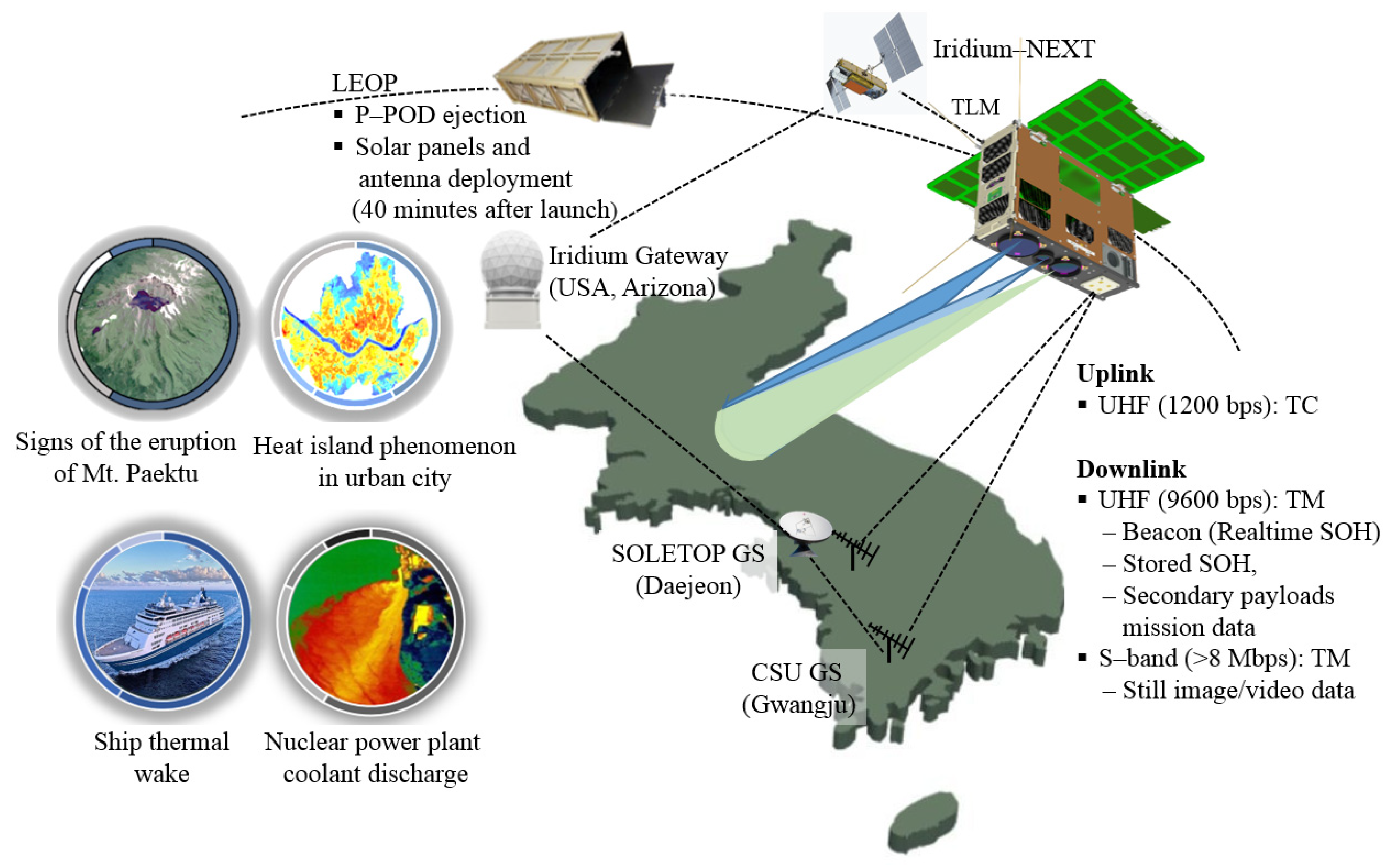
2.1. Mission Objectives and System Descriptions

Figure 1 illustrates the system architecture of the STEP Cube Lab-II CubeSat mission. The STEP Cube Lab-II CubeSat has been developed in a collaborative framework of university and start-up aerospace companies for educational and technological verification purposes. The STSL of Chosun University and a consortium team of eight domestic organizations are involved in this project to verify domestically developed space technologies and demonstrate unique nighttime video mode remote sensing capability through CubeSat. The CubeSat is equipped with three commercial off-the-shelf (COTS) remote sensing instruments onboard as the primary payload for earth remote sensing, such as an electro-optical camera (EOC), broadband infrared camera (BBIRC), and long-wave infrared camera (LWIRC). The primary objective of the STEP Cube Lab-II project is to carry out the nation’s first multi-band earth observation mission by utilizing CubeSat’s electro-optical (EO) and infrared (IR) images and videos on various targets of the Korean peninsula, including Mt. Paektu, which has recently shown signs of a volcanic eruption, observation of areas affected by forest fires, and the route of spread in areas where forest fires have occurred, analysis of the thermal island phenomenon in urban areas of metropolitan cities, observation of ship activities, and monitoring of the nuclear power plant’s coolant discharge in seawater. Furthermore, one of the space technologies to be verified in this mission is an optimized data compression method in the payload data handling system (PDHS) and payload data transmission system (PDTS) for video data processing and transmission to the ground station. Additionally, this mission also tests a high-damping VMLSA to ensure structural protection of mounted solar cells in launch vibration environments by suppressing transmitted launch loads on the solar panel and a three-pogo pin-based burn wire triggering mechanism for high holding capability at the launch stowed configuration of the solar panel and reliable release action in space. Furthermore, an optimized SADA for the acquisition of solar power maximization is one of the secondary payloads. This study is mainly focused on the on-ground experimental validation of the design effectiveness and structural safety of the VMLSA combined with P-HRM.
Table 1 presents the detailed specifications of the CubeSat system. For mission operation, the satellite orbit is selected as a sun-synchronous orbit of 700 km altitude from the earth surface and an inclination angle of 98.2° with a local time of descending node (LTDN) of 16:00 p.m. The ground station contact time of the satellite calculated from the orbital analysis is approximately 7.5 min, and access to the ground station occurs six times a day. The CubeSat mission operation life is set to one year.

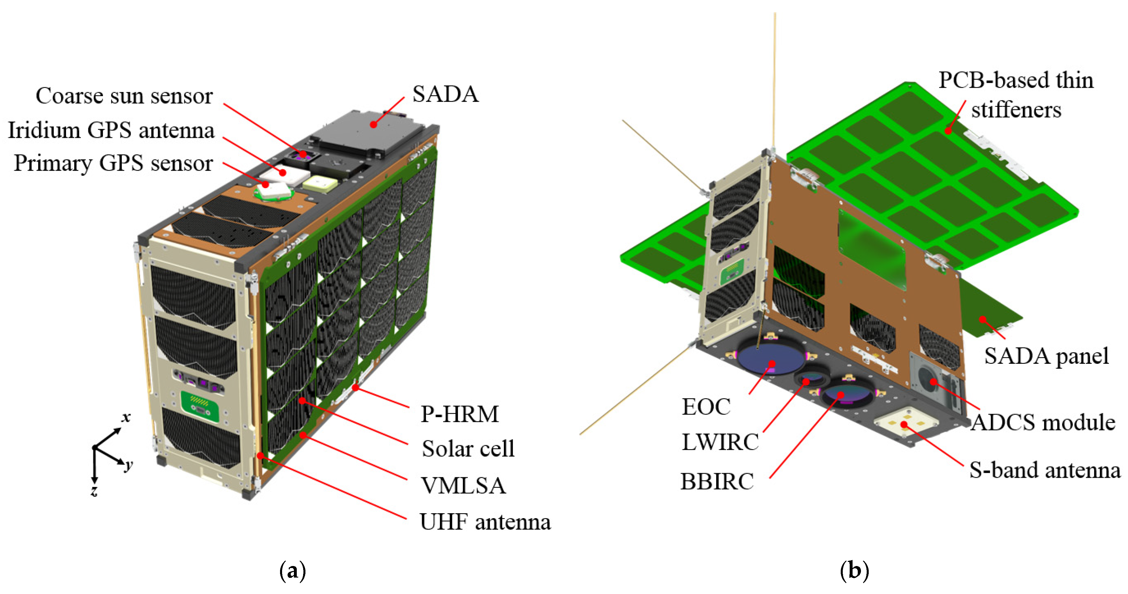
2.2. Satellite’s Configuration and Design Descriptions

Figure 2a,b demonstrate the STEP Cube Lab-II mechanical configurations at the solar panel stowed and deployed states, respectively. The CubeSat’s mechanical dimensions and total weight are 366 mm (X-axis) × 117.8 mm (Y-axis) × 238.5 mm (Z-axis) and 9.6 kg, respectively, which are within the 6U standard. The CubeSat mainly consists of COTS components enclosed in domestically developed structures, while a few interface boards and mechanical subsystems were designed and assembled by the team. The primary payload comprises three optics and sensor pairs: EOC, BBIRC, and LWIRC, which are designed to operate in staring mode and are capable of capturing images and videos nearly simultaneously from the three cameras. The performance specification of the EOC of spectral 0.38–0.94 μm wavelength range is a 10 m ground sampling distance (GSD), which covers an area of 40 km × 40 km swath width. The GSD and swath width of the BBIRC and LWIRC were 350 m and 220 km × 160 km, respectively. The maximum estimated observation times for the multi-band still imaging mode and dual-IRC video mode on the Korean peninsula during an orbit period are 5.85 s and 10 s, respectively. All commands for uplink as well as the downlink of images and telemetry will be performed using the ultra-high frequency (UHF) amateur band at a frequency of 1200–9600 bps. Additionally, the communications between CubeSat and ground stations for data transmission are accomplished by an S-band antenna with a capacity greater than 8 Mbps. For the redundancy of the satellite communication system, communication between the satellite and ground stations can be accomplished through the iridium communication network, which also enables satellite orbital determination through the iridium GPS navigation data. Furthermore, the satellite’s attitude control is accomplished by the three-axis attitude control method by the application of the XACT-15 attitude determination and control system (ADCS) [20]. To optimize the in-orbit power generation capability from the fixed-type deployable solar panels, the attitude of STEP Cube Lab-II will be set in such a way that deployable solar panels always point toward the sun direction by a 90-degree roll maneuver of the CubeSat from the nadir-pointing attitude through the ADCS, except for the periods of mission operation and ground contact. For mission accomplishment, the onboard ADCS roll maneuvers the satellite back to the nadir point attitude.

2.3. Design of Solar Panel Module with the Accommodation of Solar Cell

A deployable solar panel based on a PCB substrate using multilayered thin stiffeners attached using double-sided viscoelastic tapes is proposed for STEP Cube Lab-II CubeSat as a novel design approach to ensure structural protection of solar cells by suppressing the transmitted vibration loads on a panel in a launch environment. The holding and releasing action of the solar panel is accomplished using an optimized version of the pogo pin-based burn wire cutting release mechanism. The solar panel deployment is set to occur within 1 h of the orbital injection of STEP Cube Lab-II from the P-POD. The passive torsional force of the torsional hinges deploys and latches the panel at its projected position. Twenty AZUR space 30% efficiency triple-junction GaAs solar cells (3G30C) [9] can be mounted on the front surface of the proposed solar panel because this design strategy does not reduce the available area for solar cell accommodation. Thus, the power generation of the proposed solar panel is maximized compared to the same solar panel area by employing the aforementioned design strategies to ensure the structural safety of solar cells.
The energy balance analysis (EBA) of the CubeSat is performed to verify whether the power generation from the proposed solar cell composition is well adjusted with power consumption by the subsystems and payloads in mission scenarios, power storage for system operation in eclipse, and battery health over the mission life [21]. Table 2 shows the results of the EBA in the multi-band still imaging and IR video operation modes of earth observation. The earth observation period of the multi-band still imaging and IR video operation mode of the CubeSat is the most power-consuming phase relative to the other operating modes that were determined by the power on/off status of the hardware in operational modes. The total power consumption by the CubeSat subsystems and payloads in multi-band still imaging and IR video operation mode with a contingency margin of 10 percent is 18.38 W, which was calculated using the operating voltage and current information provided in each component’s datasheet. CubeSat’s power analysis was performed using the FreeFlyer software in accordance with the orbital information mentioned in Table 1. The AZUR space 30% efficiency triple-junction GaAs solar cell (3G30C) was considered in the analysis. The analysis result shows that the average power generation in an orbit in the worst-case scenario would be 33.29 W. The EBA result indicates that the power margin of the satellite in an orbit is 2.25 Wh, which is 5.63% of the generated power in a daylight period. Furthermore, the maximum depth of discharge (DoD) of the battery in an orbit with a battery pack capacity of 77 Wh is 13.41%, which is within the maximum 20% system requirement. The results show that the CubeSat will have a sufficient power margin and good battery health over the mission life period in the proposed composition of solar cells with the satellite’s sun-pointing attitude. The system requirement of battery DoD% less than 20 cannot be guaranteed with only body-mounted solar cells, which justifies the choice of deployable solar panels for STEP Cube Lab-II to accomplish mission objectives over the 1-year mission operation lifetime.
Table 3 summarizes the detailed mass budget of the solar panel module proposed in this study. The total mass of the proposed solar panel module is 306.5 g, which is comparatively lighter than that of the commercially available deployable solar panel for 6U CubeSat and those developed in an academic environment. For instance, the mass of the proposed solar panel module is lower by a factor of 2.04, compared to the 6U CubeSat’s solar panel module stiffened by applying additional high-pressure laminated G10 material [8].

3. A PCB-Based High-Damping Deployable Solar Panel Module

3.1. Design Description

Figure 3a,b show the demonstration model of a highly damped deployable solar panel module’s stowed and deployed configurations, respectively. The solar panel module is comprised of a PCB panel with thin stiffeners attached by adhesive tapes, a three-pogo pin-based HRM, and torsional hinges. The PCB panel of dimensions 325.4 mm × 193 mm × 1.6 mm is made up of FR4 material and provides a mechanical interface for mounting solar cells and stiffeners. Five layers of thin 0.4 mm FR4 PCB stiffeners, as shown in Figure 3, were mounted on the rear surface of the PCB panel through double-sided 3MTM 966 acrylic tapes [22]. The 3MTM 966 acrylic tape is a high-temperature adhesive that has been used in aerospace applications that comply with ASTM E596 low volatility specification criteria for space application of the National Aeronautics and Space Administration (NASA). For the attenuation of transmitted launch loads on the panel, the fundamental principle is based on constrained layer damping accomplished by the shear deformation characteristics achieved between interlaminated thin stiffeners and adhesive tapes. The basic specifications of the materials used in the solar panel module are listed in Table 4.
The stiffener attachment process on the panel is considerably simple, although the uniform bonding strength distribution in the workmanship should be controlled with intensive care. Therefore, for symmetrical attachment and easy integration of the stiffeners, four guide holes were made on the four edge corners of the PCB panel and stiffeners. The stiffener attachment process on the PCB panel is shown in Figure 4. First, prepare the materials and integration tools such as PCB panel, stiffeners, 3M966 tape, integration jig, isopropyl alcohol (IPA), torque wrench, knife, and cleaning cloth, then wipe the stiffeners and PCB panel by using a cloth moistened with IPA to remove dust contamination. The tape was cut according to the shape of the stiffener by a knife tip, put into the integration jig through the guide hole interfaces, and the process was repeated up to the specified number of stiffeners that had to be attached to the panel. The PCB panel should be placed on the last stiffener attached to the tape, and then the top guide jig has to clamp with M3 bolts fastened on the jig through a torque of 1.1 Nm to create a compression force on the specimen. As recommended by the adhesive tape datasheet [22], the adhesive bonding resin of the attached tapes must be cured for up to 72 h for secure attachment.
The number of attached stiffeners was determined by the 3U CubeSat solar panel’s experimental test results [18] while considering dynamic clearance while accommodating the P-POD. The thickness of the solar panel after the attachment of the stiffeners is 3.7 mm, which provides a lateral edge gap margin of 3.3 mm for a dynamic clearance on P-POD [11].

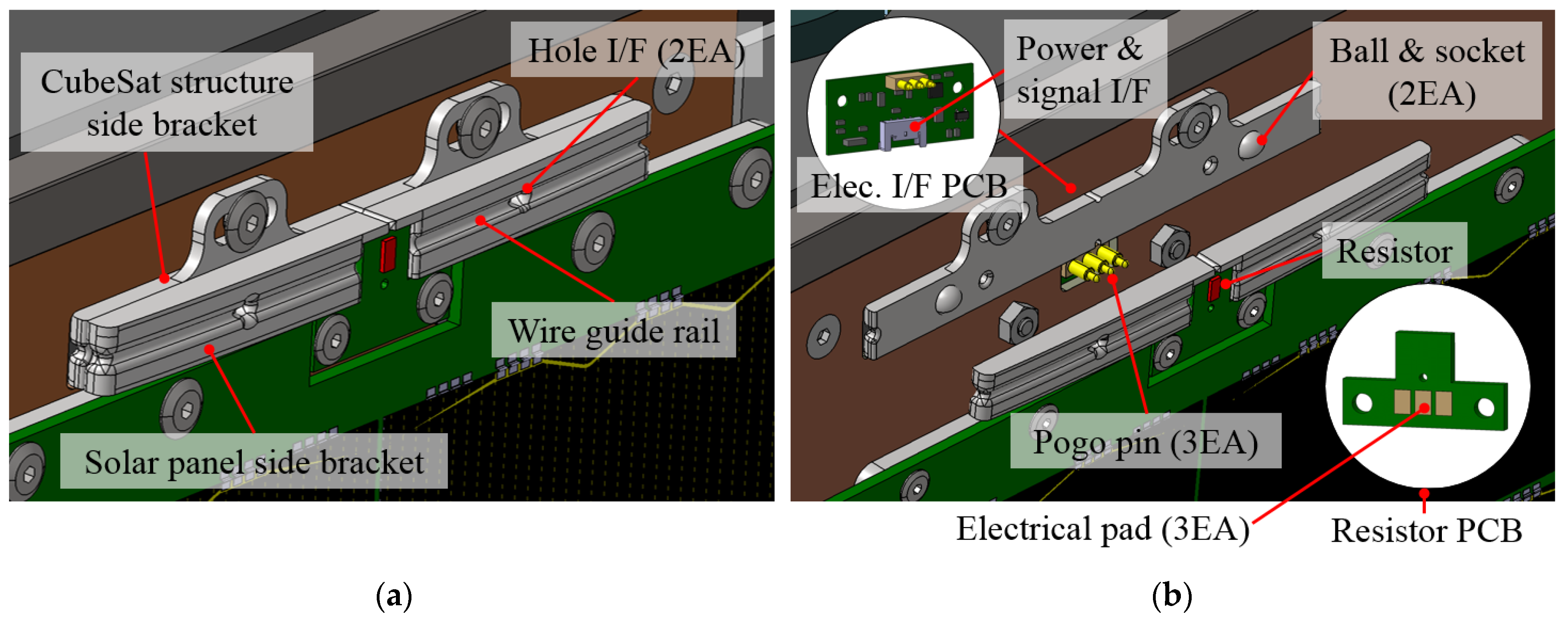
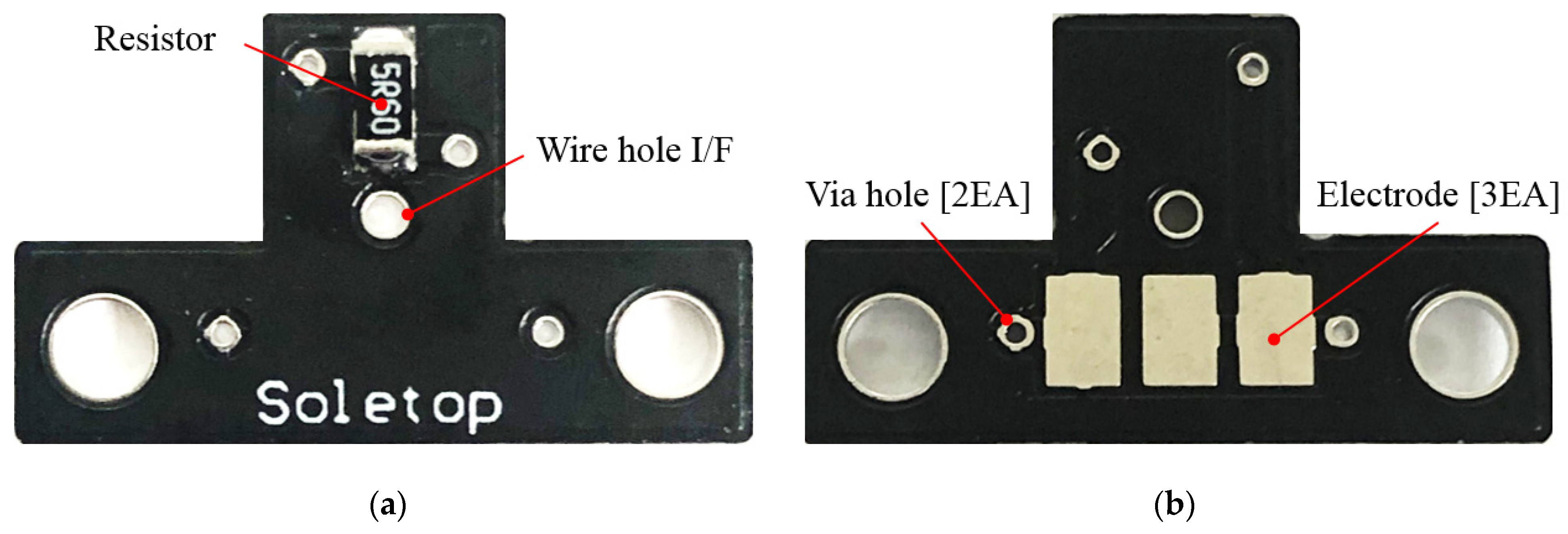
3.2. Solar Panel Holding and Release Mechanism

Figure 5a,b illustrate close-up views of the proposed three-pogo pin-based mechanism in fully and partially stowed solar panel states, respectively. The mechanism comprises pogo pins, electrical interface PCB, brackets, Dyneema wire, resistor, and resistor PCB. Park et al. [23] and Bhattarai et al. [24] investigated the applicability and effectiveness of two pogo pins in HRM, although the main purpose of using three pogo pins in the proposed mechanism is to simplify the electrical circuit by reducing the electrical components to lower the cost of the product and increase its reliability for secure release action in a harsh space environment. The main design driver for the use of the pogo pin (MP511-1111-E03100A, CFE Corporation Co., Guangdong, China) [25] connectors is the establishment of a secure electromechanical connection between the electrical interface PCB and the resistor PCB integrated at the edge of the CubeSat structure and solar panel edge, respectively. The pogo pins provide electrical current to the resistor mounted on the resistor PCB during mechanism activation. The holding constraint on the solar panel at the stowed state is achieved by tightening the Dyneema wire on the brackets. Mechanical restraint in the in-plane direction of the solar panel during the stowed configuration is accomplished by ball and socket joints made on the brackets that act as a mechanical limiter to avoid the adverse panel strike on pogo pins beyond the pogo pin’s plunger working stroke range. Additionally, the socket limits ball movement within a nominal gap, which averts the burden at the wire knot under vibration environments. To release the holding constraint on the solar panel, a resistor (3216 SMD type, Walsin Technology Co., Taipei, Taiwan) [26] was integrated on the resistor PCB as an actuator. As the mechanism is activated by the power supply in an electrical circuit, the resistor cuts the tightened wire. The panel deployment is initiated instantly by the compression force of the pogo pin plunger, 0.68 ± 0.19 N, which could rapidly or simply interrupt the circuit path to the resistor. Consequently, the hinge torsional forces deploy the solar panel to its intended angle. Table 5 lists the specifications of the hardware used in P-HRM.
Figure 6a,b illustrate the electrical system of the three-pogo pin-based mechanisms. For mechanism activation, the input voltage on the electrical circuit path to the resistor was applied to 8V, although the electrical components were supplied at 3.3 V. The optocoupler (PC817) [27] transmits electrical signals by light between two electrically isolated circuits, thus preventing high-voltage electrical malfunctions in the circuit. The power cutoff function on the mechanism is accomplished instantly after the deployment of the solar panel with the electrical circuit shown in the block diagram without employing a microcontroller unit (MCU).
Figure 7a,b illustrate resistor PCB’s front and rear views, respectively. A resistor as an actuator for solar panel release is soldered on the front side of the resistor PCB, which faces the outward direction while integrating on the solar panel. To interconnect the electrical power coming from the pogo pins to the resistor, three surface-mounted electrodes were attached to the rear surface of the resistor PCB that was mechanically connected to the resistor internally. Additionally, two via hole interfaces were made near the electrodes that were physically connected to the electrodes. In general, thermal vias are well-known methods used to enhance the heat dissipation of surface-mounted components in a PCB. However, the application of vias in the resistor PCB is to make electrodes more securely attached to the PCB surface in order to avoid the risk of electrode pad detachment due to pogo pin friction under launch vibration loads. Bhattarai et al. [24] performed a scanning electron microscope (SEM) inspection of the electrode pads after completing all the vibration tests to evaluate the frictional impact or damage caused by the tip of the pogo pins, even though the spring-loaded pin has a low friction impact on vibration loads. The thickness of the electrical contact part or curvature tip on the electrodes was only reduced by 23.88% compared to that of the 60.37 μm initial thickness. The frictional impact on the electrode under vibration load is minimal; thus, a secure physical contact can be assured even after being exposed to severe launch vibration loads because of the 1.7 mm full stroke of the spring-loaded pin of the pogo pins.
In the mechanism, pogo pins with the combination of voltage resistor divider are used to determine the panel deployment status, which provides telemetry of “1” or “0” through a buffer IC based on the current flow status in the resistor’s circuit path, where “1” implies voltage resistor divider’s output voltage. Table 6 lists the truth tables of the circuit. Once the mechanism is activated, the current flows through the resistor and the voltage resistor divider. The output voltage at the voltage resistor divider becomes approximately 0 V until the panel is deployed because the resistance value of the resistors used in the voltage resistor divider is significantly higher than that of the resistor used as an actuator for panel deployment. The electrical circuit over the resistor becomes open once the solar panel is deployed such that the output signal of the circuit becomes high, which confirms the deployment status of the solar panel. Therefore, compared to the mechanism [28], the P-HRM proposed in this study has a relatively simpler electrical circuit and is well suited to the available P-POD lateral edge gap.

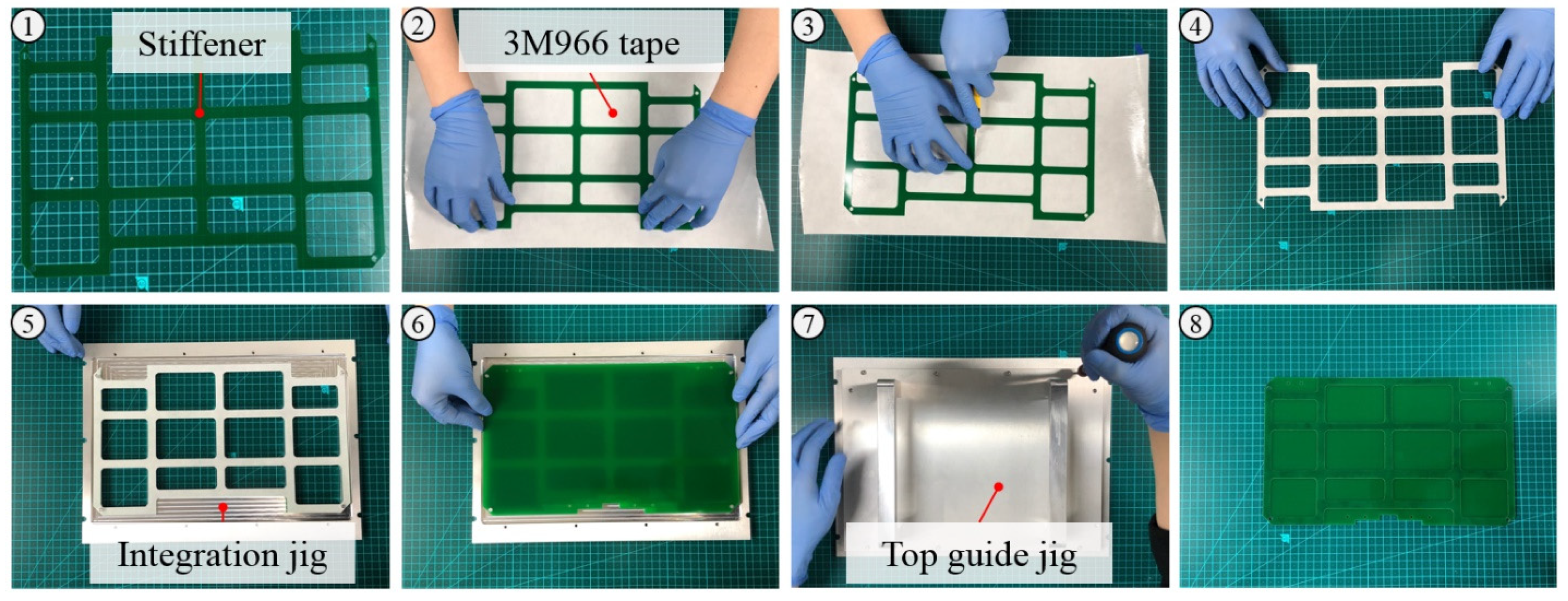
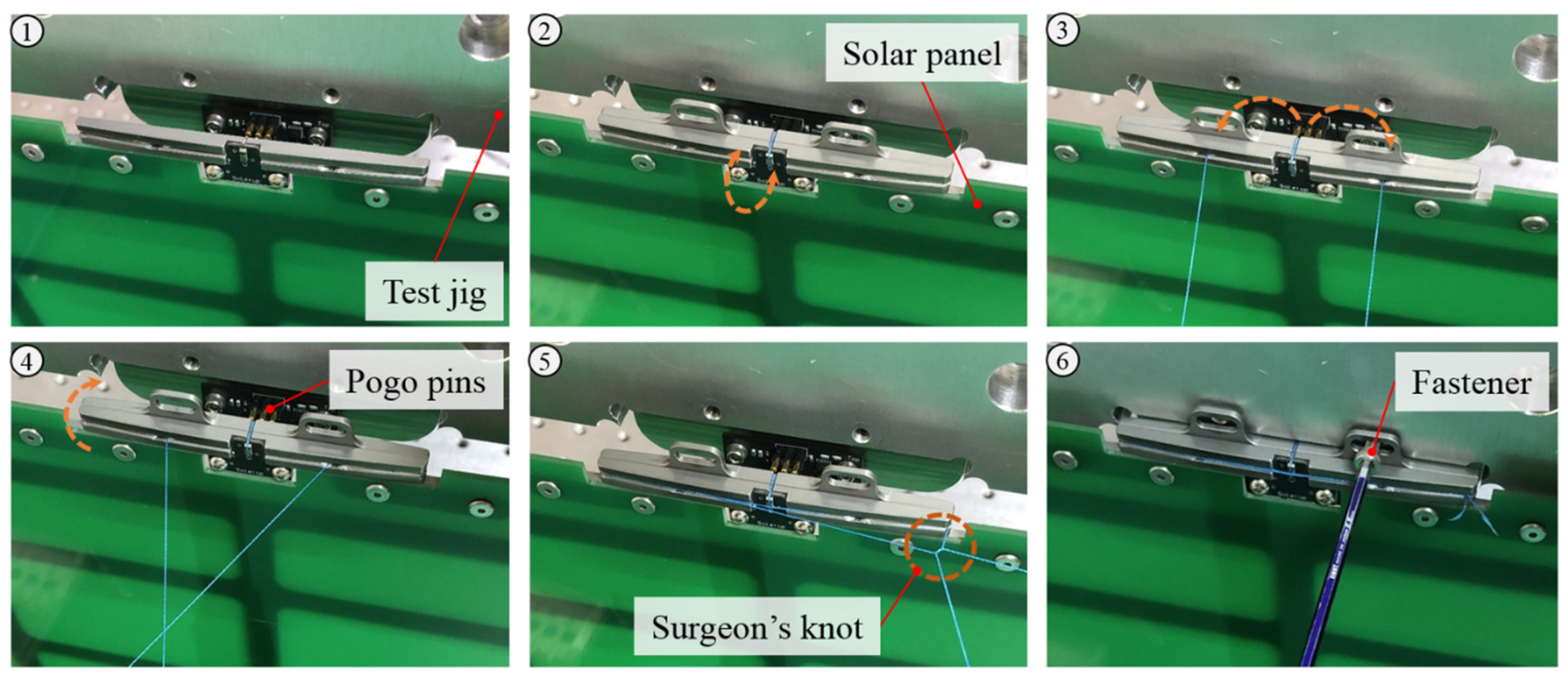
3.3. Wire-Tightening Process

The wire-tightening procedure on the brackets for the solar panel’s holding mechanical constraint is shown in Figure 8. Dyneema wire (YGK G-Soul) [29] (diameter 0.20 mm) is wound on the brackets that can bear maximum strength of 88.2 N; the panel-holding capacity can be further increased with the wire-winding numbers. The surgeon’s knot is carried out at the bracket corner for the final knotting of the wire, which helps to create a steady tight tension on the wire knot. For reliable panel release, physical contact of the wire to the resistor is mandatory. Thus, the notching guide rail is made on the bracket’s surface to prevent wire misalignment from the resistor surface under launch vibration loads. Additionally, the combination of vertical and horizontal cross-pattern winding of the wire with two additional hole interfaces in the brackets creates a secure holding constraint on the panel. The process of wire tightening to stow the solar panel is therefore significantly simpler and more reliable than conventional mechanisms.

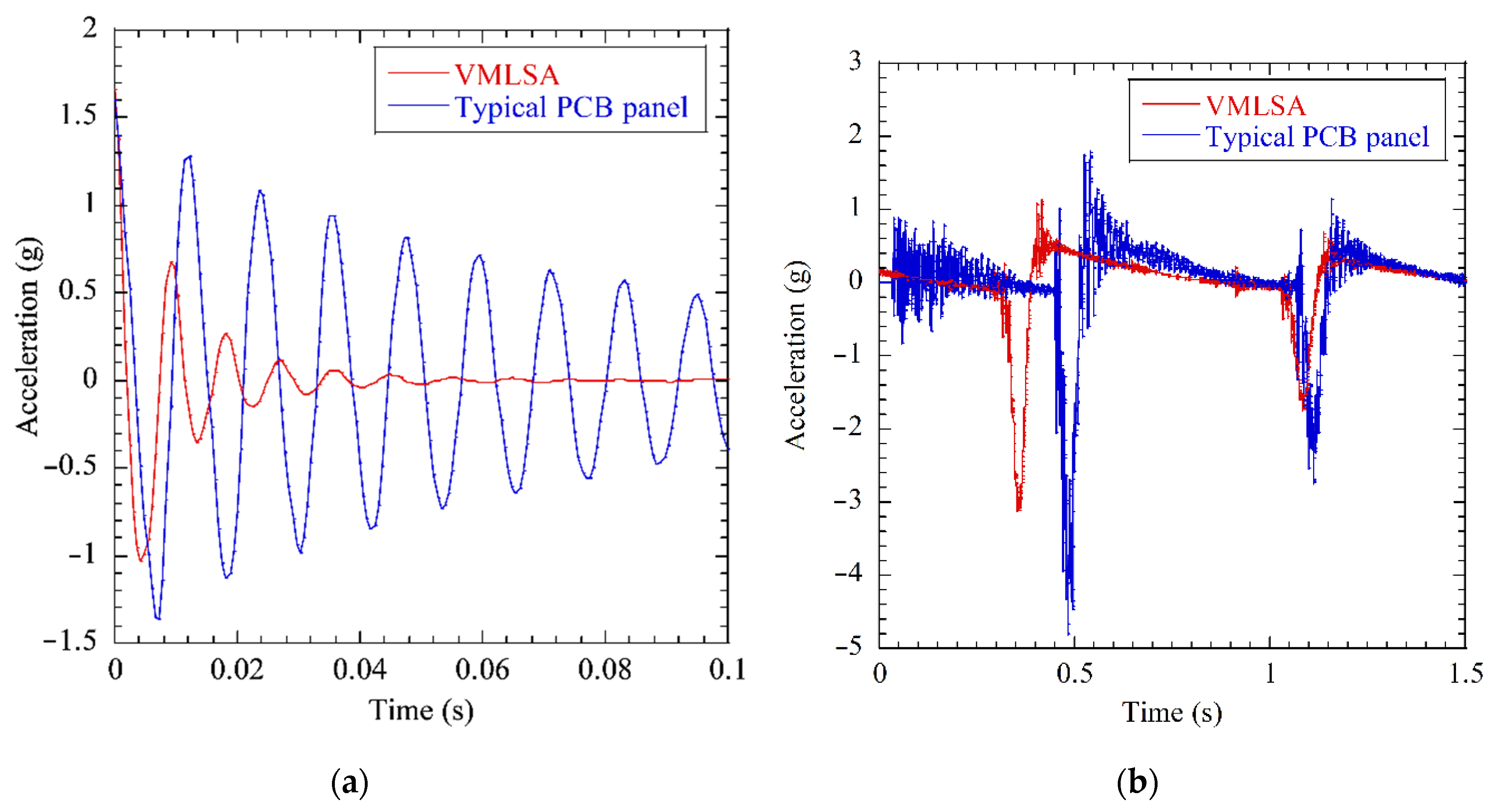
4. Dynamic Characteristics Investigation

In the constrained layer damping strategy, the transmitted vibration energy dissipation is highly dependent on the viscoelastic core layer thickness, dynamic modulus, thickness of constraining layers, and vibration frequency [30,31]. Therefore, a solar panel free-vibration test was executed at 25 °C ambient room temperature under the boundary condition in which the interfaces of the hinge and HRM holes were rigidly clamped. The roving hammer method was used to excite the solar panel in its free vibration. An accelerometer sensor was mounted at the solar panel center to obtain the time-domain frequency responses. To investigate the design usefulness or practicality for rapid suppression of panel chattering vibration during its in-orbit performance, the solar panel module’s acceleration profile under deployment was also measured in the same room temperature environment. The dynamic characteristics investigation tests of a typical PCB panel of the same size without attaching additional stiffeners were also performed to compare the results obtained from the VMLSA. Figure 9a,b show the solar panel time histories in the free-vibration tests at the rigidly mounted condition and the acceleration profile under deployment, respectively. The results illustrate that stiffeners with viscoelastic acrylic tape can effectively suppress the transmitted vibration on the solar panel.
Table 7 summarizes the solar panel’s free-vibration test results in the rigidly mounted condition. The results show that the VMLSA’s first eigenfrequency and damping ratio were 110.1 Hz and 0.141, higher by a factor of 1.33 and 3.9, respectively, compared to those of the typical PCB solar panel. The results show that the application of viscoelastic multilayered thin stiffeners significantly improved the vibration attenuation along with increased solar panel rigidity due to shear deformation characteristics and tough surface roughness between the interlaminated layers. Furthermore, this design strategy could also be advantageous for rapid attenuation of in-orbit vibration on the panel caused by rigid body motion of the satellite during slew maneuver as the panel chattering vibration under deployment was effectively reduced.

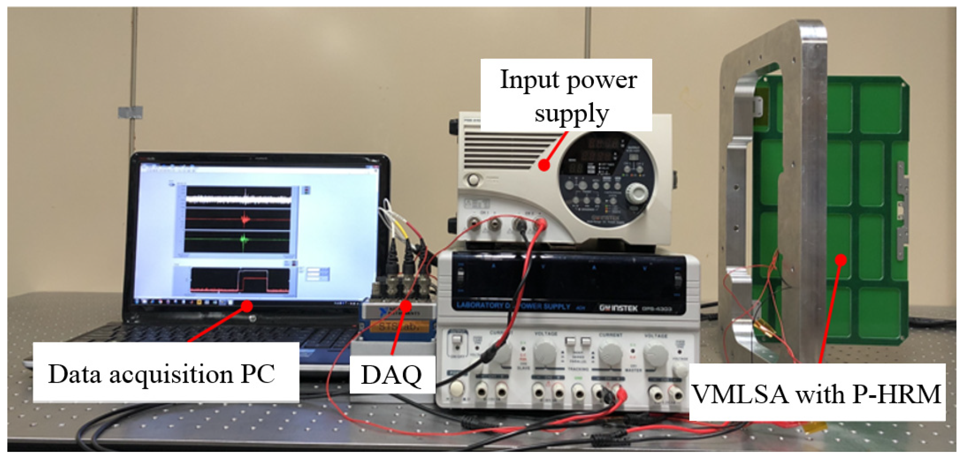
5. Experimental Validation

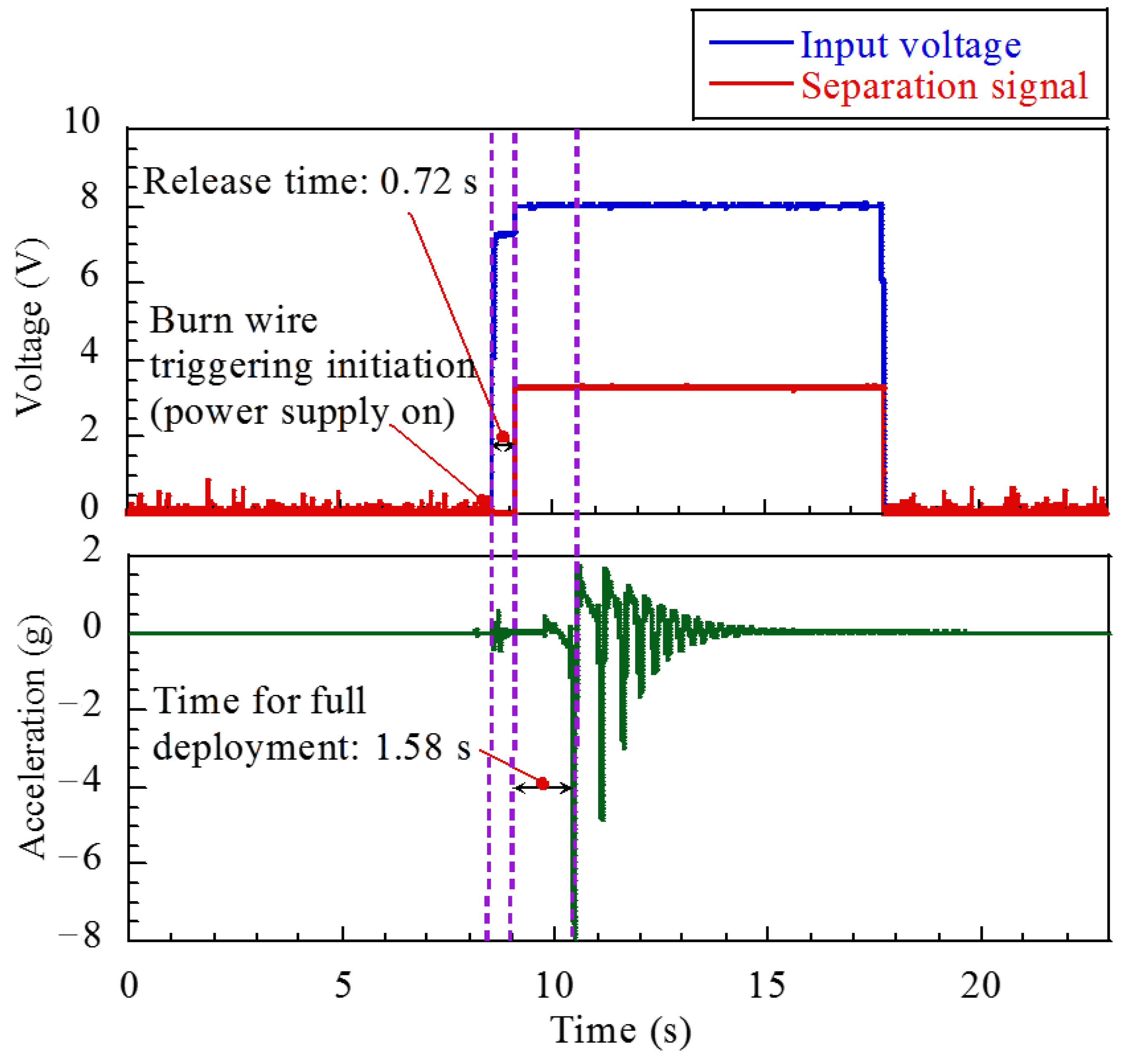
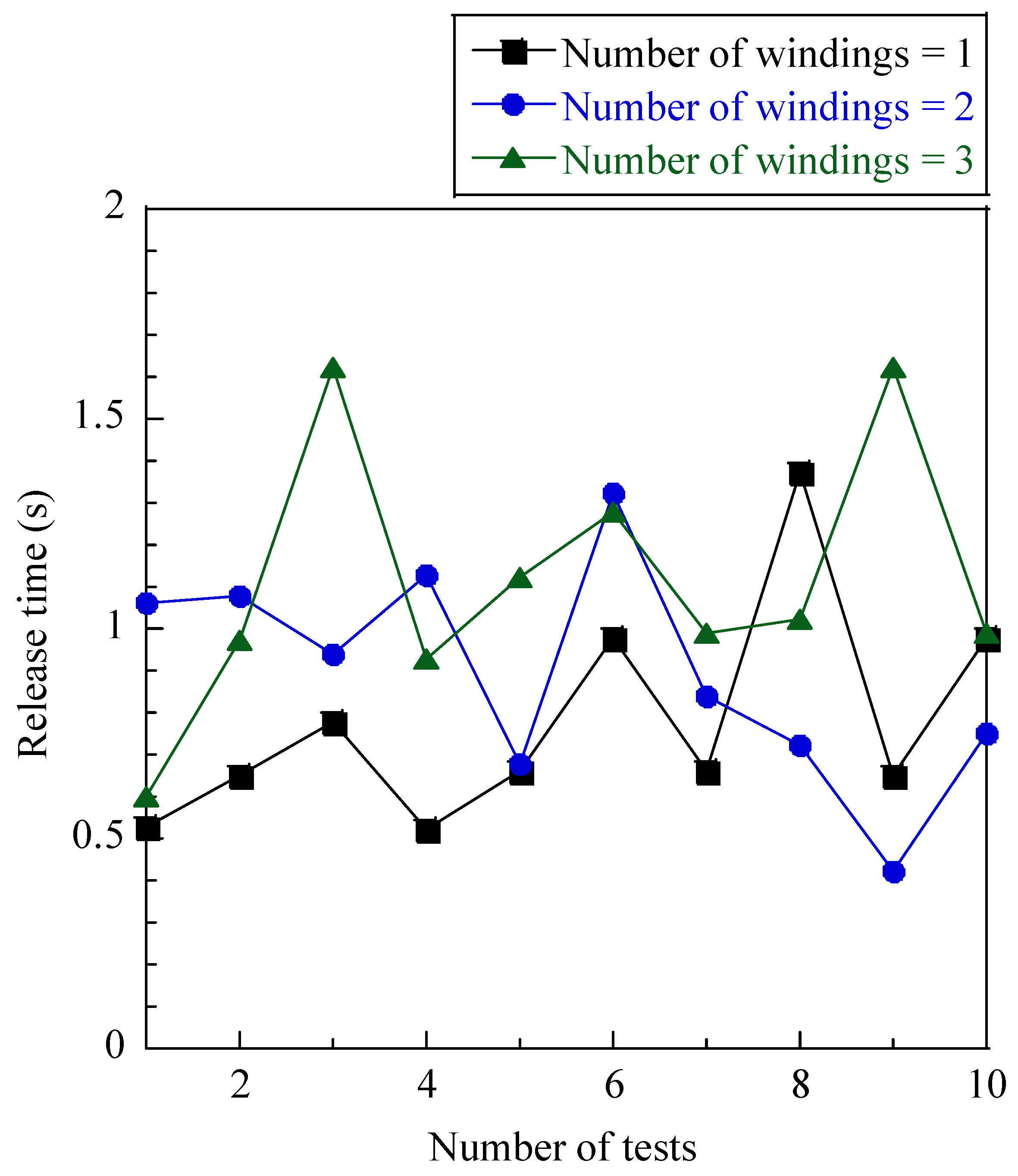
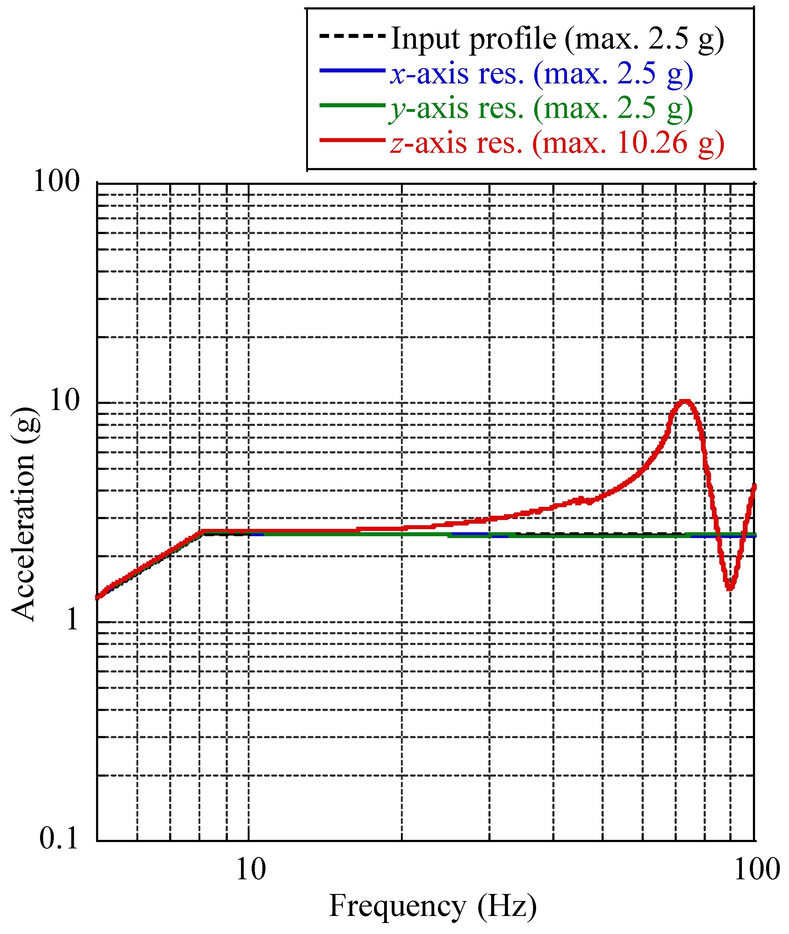
5.1. Solar Panel Deployment Test

To validate the proposed mechanism’s stable release function, the deployment tests of the solar panel were executed at an ambient room temperature of 25 °C with the experimental test setup shown in Figure 10. The qualification model of the P-HRM electrical system illustrated in Figure 6 was electrically connected to a power source for the triggering mechanism and a data acquisition (DAQ) system to determine the solar panel deployment status. In addition, an accelerometer at the center of the solar panel was attached to measure the panel acceleration responses. The solar panel’s random equivalent static analysis result showed that at least triple wire winding is required to secure a positive margin with a safety factor of 3, which is not shown here. Thus, to stow the solar panel as it is in launch configuration, triple wire winding was performed as described in the above-mentioned wire-tightening procedure.
Figure 11 shows the VMLSA release function test results. The time history of the input voltage in the mechanism and separation signal indicated that the solar panel is released at 0.72 s from the power triggering in the circuit. The solar panel’s acceleration response indicates that the complete deployment of the panel took 1.58 s after the release action was completed. The test results validated the release function of the mechanism. As intended in the design, the deployment status of the solar panel was confirmed according to the electric current flow status through the resistor mounted on the resistor PCB using pogo pins and a voltage divider circuit.
The function of the deployment mechanism must be confirmed by conducting at least 10 repeatability checks at room temperature, as several deployment tests are required during the development of CubeSat and testing phases such as run-in and acceptance testing [32]. The mechanism was therefore repeatedly released in the same test configuration as shown in Figure 10. The main objectives of the tests were to verify the repeatability of the mechanism and to identify the release time difference between single and triple wire windings. The release times are shown in Figure 12. The system functioned well in 10 repetitive activations without electrical malfunction on the circuit and no failure on the mounted resistor. However, the release time was noticeably varied in repetitive release tests because of the variable workmanship of applied tension on the knot of the wire. The mechanism’s average release time with one, two, and three wire windings in 10 repetitive triggers for each case were 0.77 s, 0.89 s, and 1.1 s, respectively. Thus, P-HRM has adequate repetitive release capability for application in actual space missions. There is no fast release requirement, but it is advantageous to cut the wire as soon as possible after the initiation of burn wire triggering in the mechanism to prevent electrical malfunction in the circuit. Furthermore, Park et al. [8] performed solar panel release tests as a function of the wire thickness within the qualification temperature range of −40 to +60 °C. The release time of the panel was slightly higher at low temperatures than that in the high-temperature environment because of the environmental effect on the variation in the heating time of the resistor. However, the release time variation from 0 to +60 °C was nominal.
Relative to the space radiation environment, the radiation hardness of electronic devices is defined according to two key aspects: cumulative effects and single event effects [33]. The most important parameter to consider when selecting electrical components for space application is the tolerance of the cumulative effects of ionizing radiation. The TID test of the electrical interface PCB was conducted under the low-level energy spectrum of 1.17 to 1.33 MeV by Cobalt-60 (60Co) radiation source for radiation hardness assurance of the P-HRM in a harsh space environment. The dose rate of 60Co was 1.67 krad per hour. The TID test duration was set to 1 h because the solar panel deployment is generally initiated within 1 h of the orbital injection of CubeSat, which gives confidence that the mechanism will not have in-orbit issues to release the panel due to radiation exposure. The voltage on the pogo pin was monitored during the test period to observe the electrical malfunction of the circuit due to the cumulative radiation exposure. The TID test result did not report any drastic variation in voltage in the circuit, while the electrical interface PCB was exposed to a 1 h cumulative radiation dose. However, the 1-year TID estimated by the space environment information system (SPENVIS) software for STEP Cube Lab-II in accordance with the system description is 10 krad. The mechanism will be activated within 1 h of the orbital injection of STEP Cube Lab-II for solar panel deployment, although further TID testing of P-HRM is scheduled to be executed under the projected 1-year total ionizing dose of 10 krad in order to assure radiation hardness over the mission life.
Furthermore, the SEE test of the electrical interface PCB of P-HRM was performed to ensure that the electrical components were robust to the in-orbit expected radiation environment. The test specimen was subjected to a high-level energy spectrum of 100 MeV in a 5 krad radiation environment. The electrical current at the pogo pin was measured during the test. The result exhibited steadiness of the current, which revealed that no SEE event occurred in the circuit. The results of these radiation tests did not report a malfunction or electrical failure in the electrical system of the P-HRM.

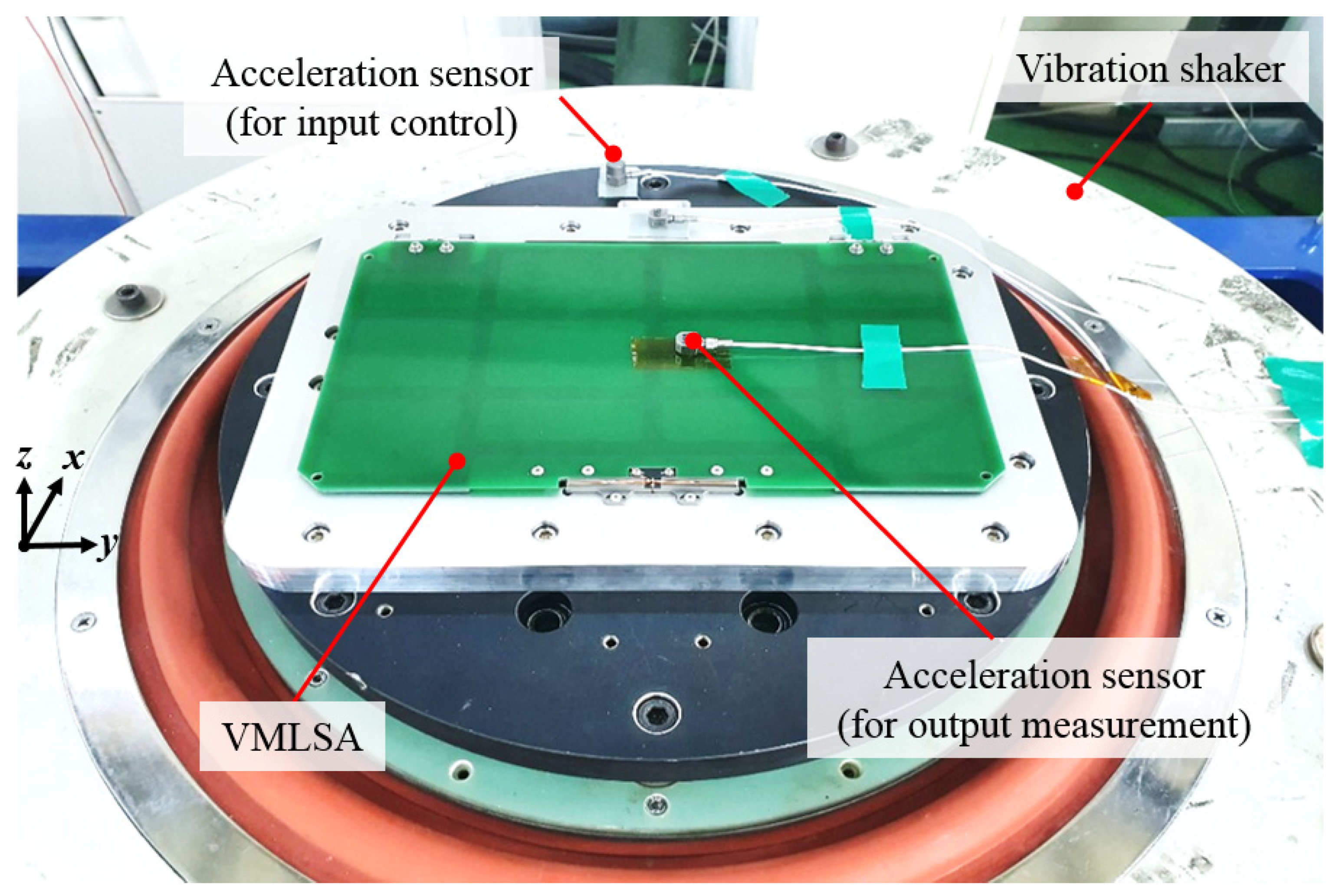
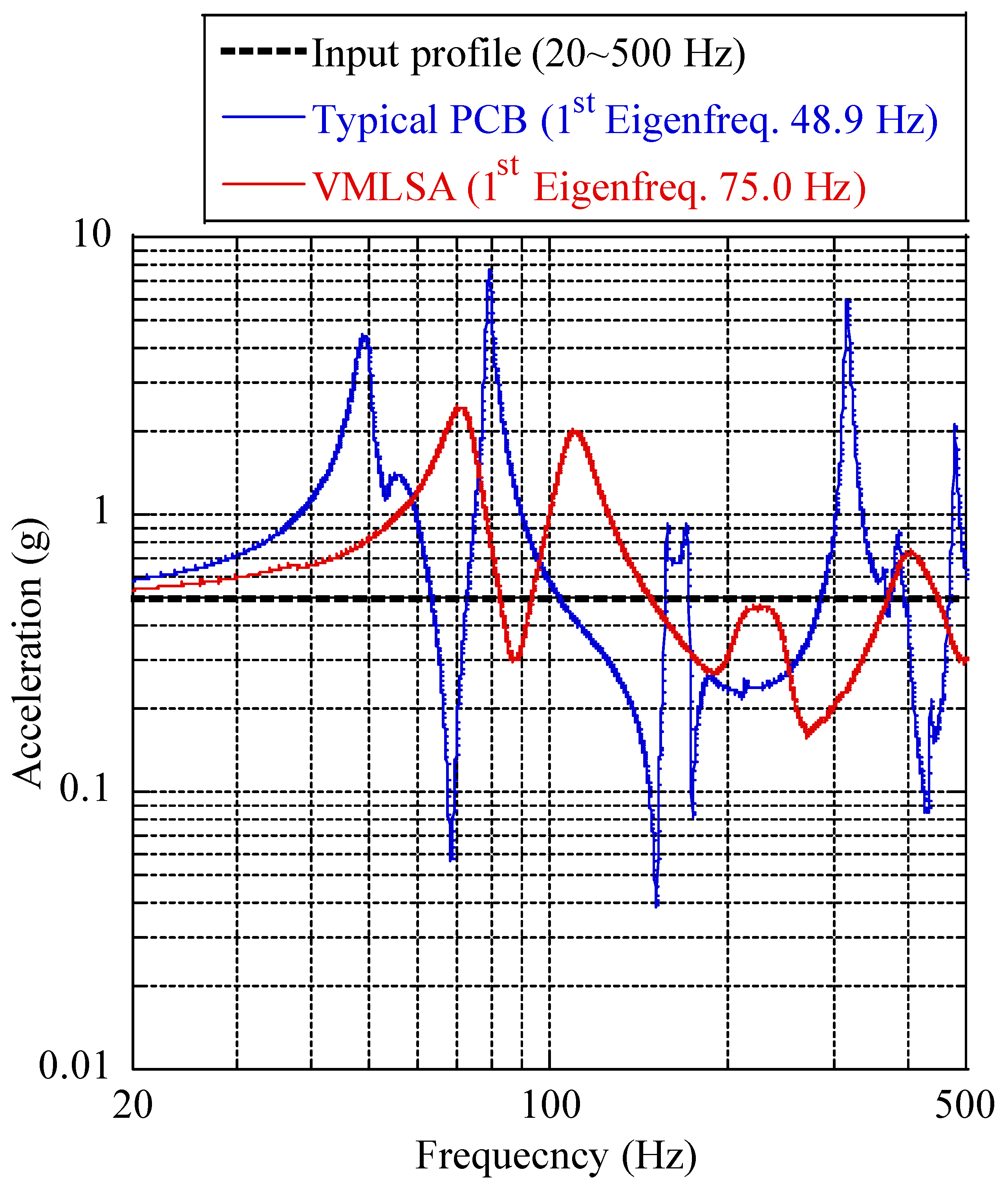
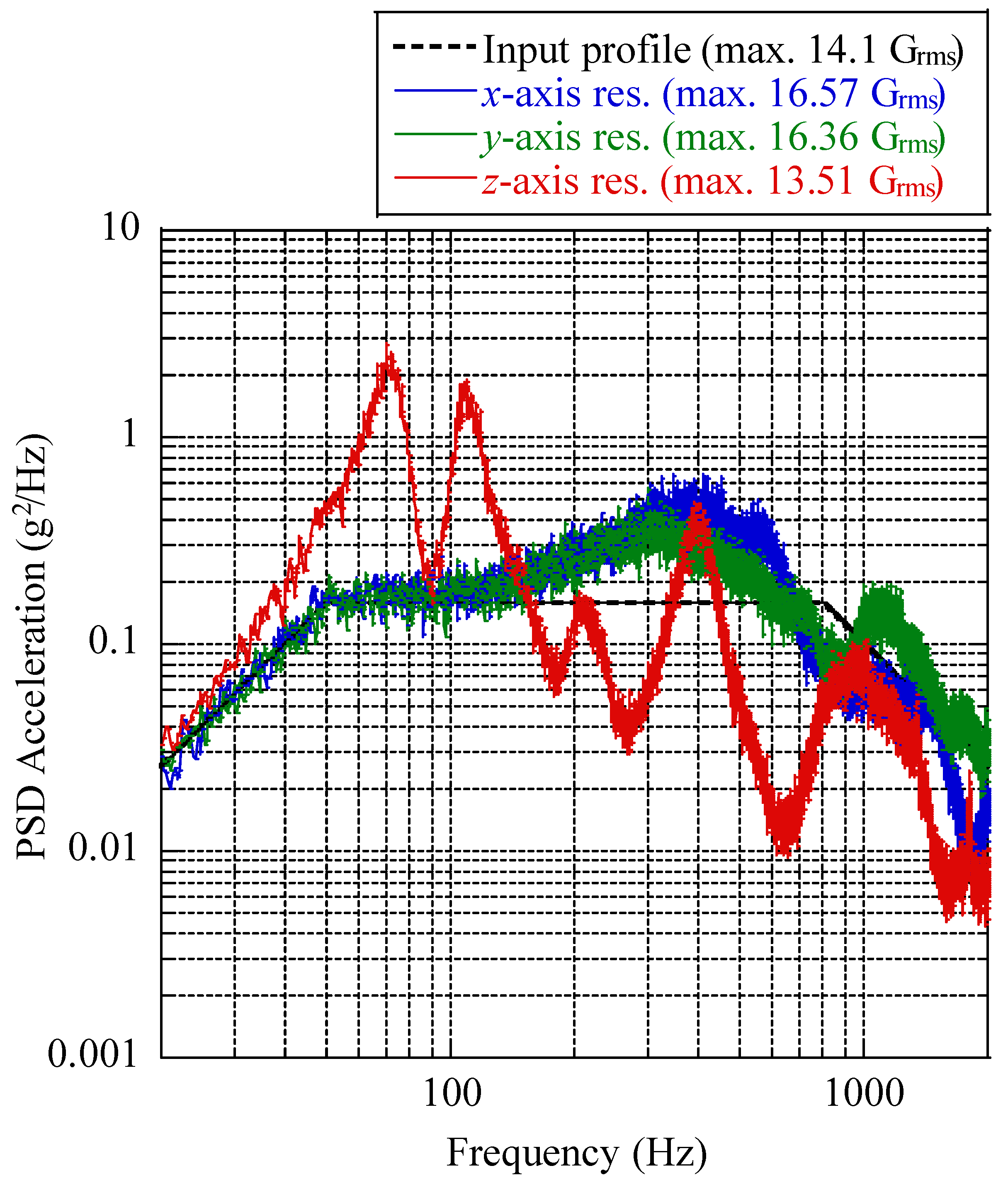
5.2. Launch Vibration Environment Test

The launch vibration tests of the proposed solar panel module were performed at ambient room temperature (20 °C) under the qualification-level sinusoidal vibration [34] and random vibration [35] launch loads to verify the damping performance and structural safety in a launch environment. Figure 13 illustrates an example of the launch vibration test setup of the VMLSA on a vibration shaker (J260/SA7M, IMV Corp., Osaka, Japan). To monitor the input vibration loads on the specimen, accelerometers were mounted on the test jig of the solar panel and the slip table of the vibration shaker. During the test, the output acceleration responses of the solar panel module were obtained using an accelerometer attached to the middle of the solar panel. The structural safety of the solar panel under vibration loads was validated by comparing first eigenfrequencies in low-level sine sweep (LLSS) tests executed before and after full-level vibration tests; the variation of first eigenfrequency in the LLSS tests must be within 5%. Additionally, after performing all vibration tests, a solar panel deployment test was executed to determine mechanism reliability.
A modal survey test was conducted before and after the aforementioned full-level vibration tests to determine the first eigenfrequency of the solar panel by a low-level sinusoidal vibration excitation on the specimen with an amplitude of 0.5 g. The z-axis LLSS response of the solar panels in the same axis excitation conducted prior to the full-level vibration tests is shown in Figure 14. The first eigenfrequency of the VMLSA in the launch stowed configuration was 75.0 Hz, which is higher than that of a typical PCB solar panel by a factor of 1.53.
The VMLSA’s corresponding axis sine vibration test results during the x-, y-, and z-axis excitations are shown in Figure 15. The qualification level of full-level sinusoidal vibration loads for small satellites, as preferred by the QB50 System requirements and recommendations [34], was applied along the axis of the solar panel, but the z-axis was the most important axis because it produced the highest dynamic deflection in comparison to the others. The solar panel’s corresponding x-, y-, and z-axes maximum acceleration responses under a sinusoidal vibration input load of 2.5 g in each excitation axis were 2.5, 2.5, and 10.26 g, respectively. A maximum 10.26 g resonance response was observed at 75 Hz on the z-axis of the VMLSA during the same axis excitation.
The VMLSA’s corresponding axis random vibration test results for each excitation axis are shown in Figure 16. The Grms values in each corresponding axis calculated from the PSD acceleration profiles under the x-, y-, and z-axis excitations were 16.57, 16.36, and 13.51, respectively. Compared to the input level random vibration profile of 14.1 Grms, the Grms of VMLSA was lower by a factor of 1.04 in the z-axis owing to the high damping achieved by the attached stiffeners.
The results of the LLSS tests conducted before and after the full-level sinusoidal and random vibration tests are summarized in Table 8. The first eigenfrequency shift of the VMLSA was within 4.85% throughout the test sequences, which is within the 5% criterion. The visual inspection of the solar panel module performed after all the vibration tests did not report dissociation and plastic deformation of the stiffeners. Thus, the structural safety of the solar panel under launch vibration loads was validated at the qualification level.
Furthermore, in the middle of the VMLSA, the maximum relative dynamic displacement under the random vibration load calculated by the 3-sigma value of acceleration Grms response was 0.12 mm. The dynamic displacement of the VMLSA is reduced by a factor of 4.3 relative to a typical PCB solar panel owing to superior damping resulting from shear deformation of viscoelastic adhesive tapes.

5.3. Thermal Vacuum Test

A TV test of the VMLSA was performed by exposing six thermal cycles at a −40 to 60 °C qualification temperature range in a 𝜙1 m TV chamber with a pressure lower than 10−5 torr to verify the solar panel’s structural safety and the release function of the P-HRM in the space environment. To measure the specimen’s temperature, thermocouples were mounted on the solar panel and electrical interface PCB. In order to determine the stabilized target temperature of the solar panel module, a thermocouple attached to the electrical interface PCB was taken as a temperature reference point (TRP). On the specimen, the target temperature stabilization was achieved by controlling the TV chamber’s shroud temperature at the 1 °C per hour rate. However, at the hot and cold plateaus of each cycle, the length of dwell time was fixed to 1 h.
The P-HRM’s state of health (SOH) check was conducted by visual inspection at each dwelling time. The solar panel deployment test was performed at −20 °C during the third cold soak phase, as it is the worst state for triggering the mechanism after satellite ejection into an orbit or trajectory. The solar panel was released without any anomalies 5.20 s after the input voltage was triggered in the mechanism. However, owing to the difference in the heating time of the resistor to cut the Dyneema wire, the release time was marginally higher than that in ambient room conditions. In addition, the electrical power dissipation from the power supply wire to the mechanism within the chamber at an extreme cold temperature and the relay time delay of the solar panel deployment signal to the DAQ system are also factors that increase the release time [36]. However, the onboard batteries of CubeSats will have sufficient power to deploy solar panels, as release action is typically carried out at the initial stage of orbital injection. After the solar panel deployment test, the remaining cycles were completed within the qualification temperature range of the solar panel.
After accomplishment of the TV test, the solar panel deployment test was performed at 25 °C room environment and the result is presented in Figure 17. The results of the release function tests of the mechanism obtained before and after vibration tests and during the TV test are plotted in the same Figure 17 to compare the release time in each event. The release time of the mechanism after the TV test was 1.5 s; the minimal difference in release time compared to that determined before the TV test is due to the thermal overstress of the resistor in six thermal cycles. Thus, these release function test results guarantee solar panel deployment in an orbit environment.
The solar panel was examined microscopically using optical microphotographs, following all the above-mentioned tests. The sidereal edge optical microphotographs taken on the solar panel before and after the TV tests did not show cracks, plastic deformation, or dissociation in the attached stiffeners. These qualification-level tests and inspection results validated the structural safety of the VMLSA under launch and in-orbit thermal environments. The optimized design of the HRM, simplified electrical circuit, and solar panel deployment experiments carried out under different test conditions led to confidence in the performance of the deployment system. The highly damped deployable solar panel module proposed herein is effective for guaranteeing the structural safety of solar cells under launch environment without reducing the area of solar cell attachment and assuring reliable release action of the panel in a space environment.

6. Conclusions

In this study, a 6U sized highly damped PCB-based deployable solar panel module combined with an optimized pogo pin-based burn HRM was proposed and tested for use in the STEP Cube Lab-II CubeSat. The proposed solar panel ensures the structural safety of solar cells under severe launch environments by reducing the solar panel’s dynamic acceleration and deflection owing to the high damping characteristics achieved by thin stiffeners and adhesive tapes. The novel three-pogo pin-based HRM has several advantages, including high loading capability in launch configuration, simpler electrical system, and guaranteed solar panel deployment in a space environment. In addition, the radiation test results of the electrical interface PCB confirmed the radiation hardness of the P-HRM to deploy the solar panel. Further TID testing of the mechanism will be performed at a system level of P-HRM under the estimated one-year total ionizing dose of 10 krad for STEP Cube Lab-II to assure radiation hardness over the mission life. Compared to a typical PCB solar panel, the relative dynamic displacement at the center of the VMLSA under random vibration loads was decreased by a factor of 4.3. The solar panel deployment tests conducted after the vibration and TV tests validated the reliability of the mechanism. In the near future, the solar panel module flight model will be manufactured and validated again by carrying out launch vibration and TV tests at the acceptance level. This design strategy could also be advantageous for rapid attenuation of in-orbit vibration on the panel caused by the satellite during the slew maneuver, which could significantly reduce the performance degradation of satellites where the rapid acquisition of the target point is required.

Author Contributions

Conceptualization, S.B., H.K. and H.-U.O.; methodology, S.B., J.-S.G., and H.-U.O.; software, S.B. and J.-S.G.; formal analysis, S.B. and J.-S.G.; validation, S.B., J.-S.G. and H.-U.O.; writing—original draft preparation, S.B.; writing—review and editing, H.-U.O.; supervision, H.K. and H.-U.O.; funding acquisition, H.-U.O. All authors have read and agreed to the published version of the manuscript.

Funding

This research was funded by the Ministry of Science and ICT (MSIT).

Institutional Review Board Statement

Not applicable.

Informed Consent Statement

Not applicable.

Data Availability Statement

The data used to support the findings of this study are available from the corresponding author upon request.

Acknowledgments

This research was supported by the Korea Aerospace Research Institute (KARI) and funded by the Ministry of Science and ICT (MSIT).

Conflicts of Interest

The authors declare no conflict of interest.

References

  1. Poghosyan, A.; Golkar, A. CubeSat evolution: Analyzing CubeSat capabilities for conducting science missions. Prog. Aerosp. Sci. 2017, 88, 59–83. [Google Scholar] [CrossRef]
  2. Santoni, F.; Piergentili, F.; Donati, S.; Perelli, M.; Negri, A.; Marino, M. An innovative deployable solar panel system for CubeSats. Acta Astronaut. 2014, 95, 210–217. [Google Scholar] [CrossRef]
  3. Anigstein, A.; Pena, R.S.S. Analysis of solar panel orientation in low altitude satellites. IEEE Trans. Aerosp. Electron. Syst. 1998, 34, 569–578. [Google Scholar] [CrossRef]
  4. Wijker, J.J. Spacecraft Structures, 1st ed.; Springer: Leiden, The Netherlands, 2008; pp. 1–504. [Google Scholar]
  5. Ampatzoglou, A.; Kostopoulos, V. Design, analysis, optimization, manufacturing, and testing of a 2U CubeSat. Int. J. Aerosp. Eng. 2018, 2018. [Google Scholar] [CrossRef] [Green Version]
  6. Chau, V.M.; Vo, H.B. Structural dynamics analysis of 3-U CubeSat. Appl. Mech. Mater. 2019, 894, 164–170. [Google Scholar] [CrossRef]
  7. Small Satellite, CubeSat Solar Panels-ISISPACE-Innovative Solutions in Space, Small Satellite Solar Panels. Available online: https://www.isispace.nl/product/isis-cubesat-solar-panels/ (accessed on 28 December 2020).
  8. Park, T.Y.; Chae, B.G.; Oh, H.U. Development of 6U CubeSat’s deployable solar panel with burn wire triggering holding and release mechanism. Int. J. Aerosp. Eng. 2019, 2019. [Google Scholar] [CrossRef]
  9. AZUR SPACE Solar Power GmbH, SPACE Solar Cells. Available online: http://www.azurspace.com/index.php/en/products/products-space/space-solar-cells (accessed on 28 December 2020).
  10. Lim, L.S.; Bui, T.D.V.; Low, K.S.; Tissera, M.S.C.; Pham, V.H.P.; Abhishek, R.; Soon, J.J.; Lew, J.M.; Aung, H.; Goh, S.T.; et al. VELOX-II: Challenges of developing a 6U nanosatellite. In Proceedings of the AIAA SPACE Conference and Exposition, Long Beach, CA, USA, 13–16 September 2016; pp. 1–11. [Google Scholar]
  11. Lee, S.; Hutputanasin, A.; Toorian, A.; Lan, W.; Munakata, R. CubeSat Design Specification Rev. 12; California Polytechnic State University: San Luis Obispo, CA, USA, 2009; pp. 1–22. Available online: https://srl.utu.fi/AuxDOC/tke/radmon/cubesat_standard.pdf (accessed on 28 December 2020).
  12. NanoPower DSP-GOMspace, Deployable Solar Panels for 3U and 6U Satellites. Available online: https://gomspace.com/shop/subsystems/power/nanopower-dsp.aspx (accessed on 28 December 2020).
  13. Solar Arrays-MMA Design LLC, Solar Arrays. Available online: https://mmadesignllc.com/products/solar-arrays/ (accessed on 25 January 2021).
  14. Thurn, A.; Huynh, S.; Koss, S.; Oppenheimer, P.; Butcher, S.; Schlater, J.; Hagan, P. A nichrome burn wire release mechanism for CubeSats. In Proceedings of the 41st Aerospace Mechanisms Symposium, Pasadena, CA, USA, 16–18 May 2012; pp. 479–488. [Google Scholar]
  15. Steinberg, D.S. Vibration Analysis for Electronic Equipment, 3rd ed.; John Wiley and Sons Inc.: New York, NY, USA, 2000; pp. 1–440. [Google Scholar]
  16. Minesugi, K.; Onoda, J. Passive vibration suppression using thin tape with viscous lamina. In Proceedings of the AIAA 36th Structures, Structural Dynamics and Materials Conference, New Orleans, LA, USA, 10–13 April 1995; pp. 200–206. [Google Scholar]
  17. Park, T.Y.; Shin, S.J.; Park, S.W.; Kang, S.J.; Oh, H.U. High-damping PCB implemented by multi-layered viscoelastic acrylic tapes for use of wedge lock applications. Eng. Fract. Mech. 2021, 241, 107370. [Google Scholar] [CrossRef]
  18. Bhattarai, S.; Kim, H.; Oh, H.U. CubeSat’s deployable solar panel with viscoelastic multi-layered stiffener for launch vibration attenuation. Int. J. Aerosp. Eng. 2020, 2020. [Google Scholar] [CrossRef]
  19. Kang, S.J.; Oh, H.U. On-orbit thermal design and validation of 1U standardized CubeSat of STEP Cube Lab. Int. J. Aerosp. Eng. 2016, 2016. [Google Scholar] [CrossRef]
  20. Components-Blue Canyon Technologies, Attitude Control System, XACT-15. Available online: https: //www.bluecanyontech.com/components (accessed on 28 December 2020).
  21. Jang, S.S.; Kim, S.H.; Lee, S.R.; Choi, J. Energy balance and power performance analysis for satellite in low earth orbit. J. Astron. Space Sci. 2010, 27, 253–262. [Google Scholar] [CrossRef] [Green Version]
  22. 3M Company, 3MTM Adhesive Transfer Tape 966-Technical Data Sheet. Available online: https://3m.citrination.com/pif/ 000314?locale=en-US (accessed on 28 December 2020).
  23. Park, T.Y.; Kim, S.H.; Kim, H.; Oh, H.U. Experimental investigation on the feasibility of using spring-loaded pogo pin as a holding and release mechanism for CubeSat’s deployable solar panels. Int. J. Aerosp. Eng. 2018, 2018. [Google Scholar] [CrossRef]
  24. Bhattarai, S.; Kim, H.; Jung, S.H.; Oh, H.U. Development of pogo pin based holding and release mechanism for deployable solar panel of CubeSat. Int. J. Aerosp. Eng. 2019, 2019. [Google Scholar] [CrossRef]
  25. CFE Company, Spring-Loaded Connectors. Available online: https://www.cfeconn.com/2-54mm-pitch-through-hole-pogo-pin-catalog.html (accessed on 28 December 2020).
  26. PSA Company, Resistors-Walsin Technology, Resistors 3216 SMD. Available online: http://www.passivecomponent.com/products/resistors/ (accessed on 28 December 2020).
  27. Optocoupler, Components101, PC817 Photo-Coupler IC. Available online: https://components101.com/ics/pc817-ic-pinout-equivalent-datasheet (accessed on 28 December 2020).
  28. Bhattarai, S.; Go, J.S.; Kim, H.; Oh, H.U. Experimental validation of a highly damped deployable solar panel module with a pogo pin-based burn wire triggering release mechanism. Int. J. Aerosp. Eng. 2020, 2020. [Google Scholar] [CrossRef]
  29. YGK Fishing Wire, YGK G-Soul Super Jigman Braid. Available online: https://www.tsourosmarine.gr/en/braids/1402-ygk-g-soul-super-jigmanbraid.html#/12-colormulticolored/4816-diameter_mm_cm-0_205_mm (accessed on 28 December 2020).
  30. Tian, S.; Xu, Z.; Wu, Q.; Qin, C. Dimensionless analysis of segmented constrained layer damping treatments with modal strain energy method. Shock Vib. 2016, 2016. [Google Scholar] [CrossRef] [Green Version]
  31. Liu, T.X.; Hua, H.X.; Zhang, Z. Robust control of plate vibration via active constrained layer damping. Thin Walled Struct. 2004, 42, 427–448. [Google Scholar] [CrossRef]
  32. ECSS-E-ST-33-01C Rev.2-Mechanisms. Space Engineering Mechanisms, ECSS Secretariat ESA-ESTEC Requirements & Standards Division; European Cooperation for Space Standardization: Noordwijk, The Netherlands, 2019; pp. 1–97. Available online: https://ecss.nl/standard/ecss-e-st-33-01c-rev-2-1-march-2019-space-engineering-mechanisms/ (accessed on 28 December 2020).
  33. Duzellier, S. Radiation effects on electronic devices in space. Aerosp. Sci. Technol. 2005, 9, 93–99. [Google Scholar] [CrossRef]
  34. Singarayar, F.; Reinhard, R.; Asma, C.; Thoemel, J.; Scholz, T.; Bernal, C.; Weggelaar, W.; Kataria, G.S.D.; Richard, M. QB50 System Requirements and Recommendations. 2013, pp. 1–28. Available online: https://www.qb50.eu/index.php/techdocs/category/QB50_Systems_Requirements_issue_44835.pdf?download=30:qb50-docs (accessed on 28 December 2020).
  35. GEVS: GSFC-STD-7000A. General Environmental Verification Standard (GEVS) for GSFC Flight Programs and Projects; NASA Goddard Space Flight Center: Greenbelt, MD, USA, 2013; pp. 1–203. Available online: https://standards.nasa.gov/standard/gsfc/gsfc-std-7000 (accessed on 28 December 2020).
  36. Malagoli, M.; Allewaert, Y. Improvement of the wire rating standards based on TV testing and thermal modeling. In Proceedings of the 48th International Conference on Environmental Systems, Albuquerque, NM, USA, 8–12 July 2018; pp. 1–15. [Google Scholar]
Figure 1. The system architecture of the Space Technology Experimental Project CubeSat Laboratory (STEP Cube Lab)-II CubeSat’s mission.
Aerospace 08 00064 g001
Figure 2. STEP Cube Lab-II’s mechanical configurations: (a) solar panel stowed and (b) solar panel deployed.
Aerospace 08 00064 g002
Figure 3. Configurations of a highly damped deployable solar panel module’s demonstration model: (a) stowed and (b) deployed.
Aerospace 08 00064 g003
Figure 4. Integration process of a stiffeners on the PCB panel.
Aerospace 08 00064 g004
Figure 5. Configurations of three-pogo pin-based HRM: (a) solar panel fully stowed and (b) solar panel partially stowed.
Aerospace 08 00064 g005
Figure 6. Three-pogo pin-based mechanism’s electrical system: (a) front and rear view of electrical interface PCB (dimensions: 34 mm × 16 mm × 1 mm) (b) schematic block diagram.
Aerospace 08 00064 g006
Figure 7. Mechanical configuration of the burn resistor PCB: (a) front view and (b) rear view.
Aerospace 08 00064 g007
Figure 8. Solar panel’s wire-tightening process.
Aerospace 08 00064 g008
Figure 9. Dynamic characteristics investigation results of the solar panels: (a) time histories of free-vibration response in rigidly mounted condition and (b) acceleration profile under deployment.
Aerospace 08 00064 g009
Figure 10. The solar panel deployment test setup.
Aerospace 08 00064 g010
Figure 11. The solar panel’s deployment test results.
Aerospace 08 00064 g011
Figure 12. Release times of the proposed mechanism in repetitive release function test.
Aerospace 08 00064 g012
Figure 13. An example of launch vibration test setup of VMLSA on a vibration shaker.
Aerospace 08 00064 g013
Figure 14. Low-level sine sweep test results in z-axis excitation.
Aerospace 08 00064 g014
Figure 15. The results of VMLSA’s corresponding axis sine vibration tests in the x-, y-, and z-axis excitations.
Aerospace 08 00064 g015
Figure 16. The results of VMLSA’s corresponding axis random vibration tests in the x-, y-, and z-axis excitations.
Aerospace 08 00064 g016
Figure 17. Summary of release time of the mechanism at each test event.
Aerospace 08 00064 g017
Table 1. Detailed system specifications of the STEP Cube Lab-II.
ItemsSpecifications
Satellite nameSTEP Cube Lab-II
Size (mm)366 (X) × 117.8 (Y) × 238.5 (Z)
Weight (kg)9.6
Orbital parameterOrbit: Sun-synchronous orbit
Altitude: 700 km
Orbital inclination angle: 98.2 deg.
Local time of descending node (LTDN): 16:00 p.m
Mission payloadPrimary payloads:
EOC, BBIRC, LWIRC
Secondary payloads:
PDHS and PDTS, VMLSA, P-HRM, SADA
Camera performanceCameraEOCBBIRCLWIRC
GSD (m)10350350
Observation width (km)40 × 40220 × 160220 × 160
Wave length range (μm)0.38–0.943–149–12
Observation mission time (s)Multi-band still imaging mode: 5.85
BBIRC and LWIRC video mode: 10
Ground station contact7.5 Minutes (Average)
Communication
system
UplinkUHF band: 1200 bps Audio frequency shift keying (AFSK)
DownlinkUHF band: 9600 bps Gaussian minimum shift keying (GMSK)S-band: >8 Mbps
16-ary amplitude and phase shift keying
(16-APSK)
Attitude control system3-axis Attitude control method
Mission life1 Year
Table 2. Energy balance analysis in mission operation mode of Earth observation.
Time (min)ParameterPower (W)Power
(Wh)
Charge/
Discharge (Wh)
Remarks
Daylight72Generation33.2939.95
Consumption−18.38−22.06
Average power for charging17.89
Actual power for charging (Considering conversion eff.)11.44
Eclipse27Consumption−18.38−9.19−9.19
Power margin2.25
Power budget (%)5.63Req.: >0
Battery depth of discharge (DoD) (%)13.41Req.: <20
Table 3. Detailed mass budget of the proposed solar panel model.
ItemsMass (g)
Printed circuit board (PCB) panel201.5
Thin stiffeners85
Viscoelastic tapes3
Pogo pin-based HRM6
Hinges and fasteners11
Total306.5
Table 4. Specifications of materials used in the solar panel module.
ItemDetailsValue
FR4Elastic modulus (Pa)18.73 × 10⁹
Density (kg/m3)1850
Poisson’s ratio0.136
Thermal conductivity (W/mK)0.29
Adhesive tape [22]Manufacturer3M Company
Adhesive materialAcrylic
Adhesive thickness (mm)0.06
ColorTransparent
Allowable temperature range (°C)−40 to 232
Thermal conductivity at 41 °C (W/mK)0.178
Coefficient of thermal expansion (ppm/°C)1.99
Adhesive strength to steel (N/100 mm)159
Total mass loss (TML) and Collected volatile condensable material (CVCM) outgassing (%)0.93, 0.01
Table 5. Specifications of the hardware used in the three-pogo pin-based HRM.
ItemsDetailsValue
Pogo pinManufactureCFE Corporation Co.
Voltage and current (V, A)12, 3
Max. electrical contact resistance (mΩ)50
Life test (Cycle)100,000
Qualification temperature range (°C)−40 to 85
Spring force (N)0.68 ± 0.19
Total length (mm)9
Full stroke (mm)1.4
Working stroke (mm)1.0
WireManufactureYGK
MaterialDyneema
Diameter (mm)0.205
Max. allowable force (N)88.2
ResistorManufactureWalsin technology Co., Taipei, Taiwan
PackageSMD Type
Electrical resistance (ohm)4.7
Resistance tolerance (%)±1
Max. power dissipation (W)0.25
Table 6. Circuit truth table for deployment status of solar panel.
InputSolar Panel Deployment Status
UndeployedDeployed
VinEnablePogo pin voltageOutput voltagePogo pin voltageOutput voltage
111011
100000
Table 7. Free-vibration test results of the solar panels in rigidly mounted condition.
Solar Panel1st Eigenfrequency (Hz)Damping Ratio
Typical PCB panel82.60.036
VMLSA110.10.141
Table 8. Results of the VMLSA’s low-level sine sweep (LLSS) tests conducted before and after full-level vibration tests.
TestExcitation AxisStatusCorresponding Axis
1st Eigenfrequency (Hz)
Frequency Shift Difference (%)
Sine vibrationxBefore835.20.19
After833.6
yBefore602.40
After602.4
zBefore75.00.93
After74.3
Random vibrationxBefore833.60.19
After832.0
yBefore602.40
After602.4
zBefore74.34.85
After70.7
Publisher’s Note: MDPI stays neutral with regard to jurisdictional claims in published maps and institutional affiliations.

