1. Introduction
The problems in the interaction of a shock wave with plasma structures can be considered as part of the direction of supersonic hypersonic flow control, since it simulates the interaction of energy sources with a bow shock wave created by an aerodynamic (AD) body in the flow. Currently, the research of flow/flight control via energy deposition is at the forefront of investigations in aerospace engineering. To solve the problems of controlling supersonic/hypersonic flows and shock wave configurations, improving the flow process, reducing aerodynamic drag, controlling the bow shock wave and boundary layers, it was proposed to supply energy both to the incoming flow, and on the surfaces of AD bodies.
In [
1], D. Knight presented a review of CFD methods for the issue of studying the shock interactions in nonequilibrium laminar flows. In an overview [
2], M. Ahmed and N. Qin presented a comparison of efficiency of various types of devices, mechanical devices (spikes), fluidic devices (opposing jets), and energy deposition devices to control the flowfield structure, drag and lift forces, surface pressure, heating and flow instabilities. A. Russel et al. presented the works on energy deposition into supersonic flows to control shock-wave configurations due to electro-gasdynamic action and Joule heating [
3]. In [
4], S. Leonov et al. reviewed the plasma base methods for control of flow and shock wave configurations by the creation of different types of gas discharge near surfaces of AD bodies.
For the purpose of flow control, bow shock wave control in particular, various types of gas discharges, as well as the imposition of external electric and magnetic fields can be used. Experimental results of the effect of longitudinal energy supply by a microwave discharge on the standoff and propagation of a bow shock wave are presented in the research of Yu. Kolesnichenko et al. [
5]. The laser pulse effect was investigated by P. Tretyakov et al. [
6] and by L. Myrabo et al. [
7]. Pulsed-periodic high-voltage discharges for this purpose was used by V. Bityurin et al. [
8] and D. Roupassov et al. [
9]. In [
10], K. Kourtzanidis et al. investigated the plasma influence on bow shock wave configuration by means of gas discharge, created near the surface of AD body, and showed the possibility of influence to the shock position by plasma effects.
The possibility of controlling shock waves by magnetohydrodynamic methods was experimentally shown by T. Lapushkina et al. in [
11]. In [
12], Q. Sun et al. investigated the effect of an arc gas discharge on the position of an oblique shock wave and on the distribution of the flow pressure. The results are explained by thermal effects and modeled in [
13] by H. Yan, et al. The thermal effect on a shock wave propagating in the wake of a nanosecond high-energy discharge, called a plasma sheet, is considered by I. Znamenskaya, et al. [
14]. O. Azarova obtained the vortex structure of the shock layer region formed under the action of energy source, and proposed a vortex mechanism of action on the body, leading to a decrease in its wave drag. Additionally, it was shown that the initialization of the vortex occurs as a result of the manifestation of the Richtmyer-Meshkov instability [
15,
16].
The creation of plasma temperature inhomogeneities along the path of propagation of shock waves can lead to a change in its shape and velocity. This has been shown by experiments on the interaction of shock waves with plasma structures. In [
17], N. Apazidis et al. used a set of heated thin wires to create thermal and density inhomogeneities of various geometric configurations in air, which led to the generation of the Richtmyer-Meshkov instability and a train of vortices generated by the Kelvin-Helmholtz instability. In [
18], V. Bityurin et al. observed the curvature of the shock wave as it passed through the region of a longitudinal pulsed discharge. In [
19,
20,
21] S. Leonov et al. investigated the influence of an inhomogeneously layered plasma on the position of the reflected shock wave. In the experiments, the blurring of the front of the reflected shock wave was obtained due to the organization of a system of plasma filaments created by a high-frequency discharge [
20,
21]. In [
22] T. Gan et al. used an array of sixteen surface arc plasma actuators to impact on the shock wave in the boundary layer which provided the disappearance of the foot part of the separation shock wave.
The curvature of the shock wave and generation of a contact discontinuity caused by the interaction of the shock wave with the glow discharge region were investigated by T. Lapushkina, et al. [
23,
24]. The effect of an ionization-unstable discharge on a plane shock wave was obtained and numerically studied [
24]. Due to this interaction, blurring, curvature and the disappearance of the shock front were obtained. In our works the possibility of the formation of flow regions behind the wave front with significantly increased values of the gas temperature due to the interaction of a thermally stratified energy source with the shock wave front has been shown [
25]. In addition, the influence of a thermally stratified energy source on the supersonic flow around an AD body was investigated and a new multi-vortex mechanism of the action of the energy source on the body surface has been established [
26]. In our previous article, the redistribution of energy types in a curved shock wave under the conditions of the experiment [
24] was estimated for M = 2 and 5 [
27].
Our current paper focuses on the interaction of a preliminary plane shock wave with an area of thermally stratified energy source, which is accompanied by generation of instabilities and vortices. The study is based on the same ideas used in [
27], but here we consider the redistribution of different types of energy for hypersonic shock wave velocities. The purpose of this work is to establish how this redistribution depends on the shock wave Mach number, which varies from 6 to 12, and on the degree of gas rarefaction in the energy source layers. In addition, we aimed to obtain and study the complicated vortex shock-wave structures, characterized by multiple manifestation of the Richtmyer-Meshkov instabilities. The research can be important for achievement of high-speed flow control and improvement of the conditions for the processes of mixing and ignition in jets and combustion chambers.
2. Numerical Method and Statement of the Problem
The effect of an energy source in the form of a thermally stratified plasma region on an initially flat shock wave is simulated based on the Navier-Stokes system of equations for viscous and heat conductive gas (air) [
28] (p. 329).
Here Re is the Reynolds number (Re = 9500) and Pr is the Prandtl number (Pr = 0.7), ρ,
p,
u,
v are the gas density, pressure,
x- and
y- are the velocity components; ε is the specific internal energy,
which corresponds to the state equation of the perfect gas. For the dependence of dynamic viscosity µ on temperature the Sutherland law,
with the constant
s1 = 0.41 (120K) was used. It was assumed that the coefficient of thermal conductivity
k depends on temperature as
To describe the thermodynamic properties of the plasma region the “effective value” of the ratio of specific heats γ = 1.2 was accepted. This value of γ corresponds to the degree of non-equilibrium of 0.015 and to the ionization degree of the gas medium of 0.00015 [
10].
The problem is solved in the dimensionless variables. Dimensionless parameters for time
t, spatial variables
x,
y, velocity components
u,
v, sound velocity
c, gas density ρ, pressure
p, and temperature
T are expressed throw the dimensional ones (marked with the index “dim”) as follows:
Here the following scales for the parameters are accepted:
where the index ∞ denotes the parameters of undisturbed flow. Normalizing values for density and pressure, ρ
n = 0.01205 kg/m
3 and
pn = 1013.25 Pa, and the Reynolds number Re = 9500 corresponds to the conditions of the experiments in [
24].
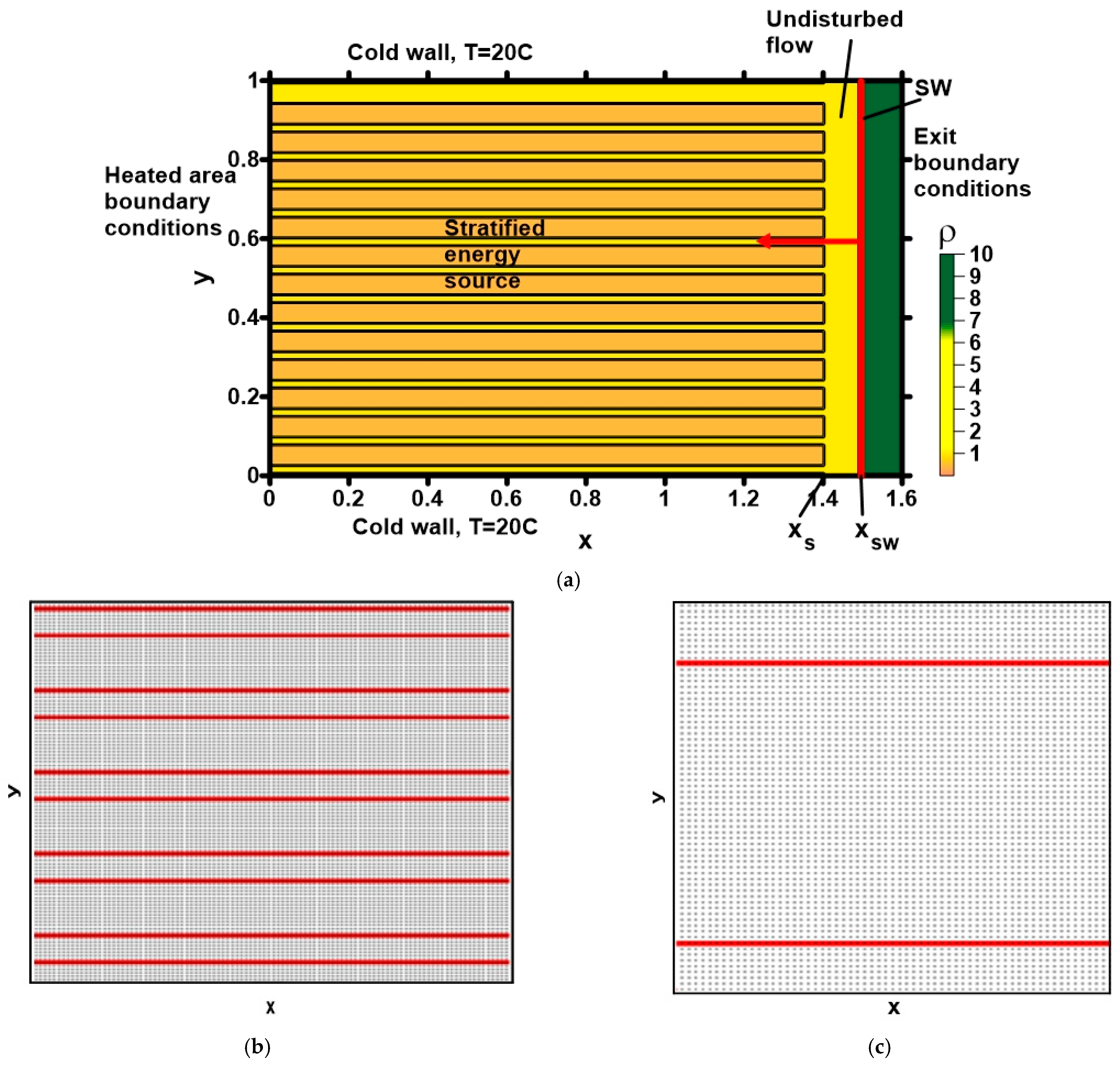
The effect of the energy source was modeled by a stationary region of heated gas layers of the same width with zero velocities and the reduced density, ρ
s = αρ
∞. Here, the parameter α characterizes the medium rarefaction, α < 1. The pressure in the source layers was equal to its undisturbed value, so, the temperature was increased in these layers. The gaps between the layers had a width equal to a half of a layer width. Below, for brevity, such a heated area is referred to as an energy source. This heated area is set at the initial time instant at some distance from the shock wave (SW),
xsw is the initial shock wave coordinate, and
xs is the stratified energy source boundary coordinate (
Figure 1a).
Horizontal walls were supposed to be cold with the value of undisturbed flow temperature, which is in accordance with the experimental conditions. As was shown in [
23], these boundary conditions provide the curvature of the shock wave front, which is adequate to that obtained in experiments. Additionally, the adhesion conditions and the condition of absence of the flows normal to the walls for the according parameters were employed.
The domestic numerical code was employed based on the conservative difference schemes of the second order of approximation in space and in time [
29]. The TVD variant of the scheme was used, with the limiter introducing to the scheme guided by the min-mod approach. The schemes are constructed on staggered grids and use a stencil of the Lax’s scheme. For the second approximation order obtaining the systems for the space derivatives were employed. There were 2000 nodes on the transverse size of the computation domain (1.6 × 10
6 nodes in the calculation area, counting the central node). Location of the stratified energy source on difference grid in enlarged form is presented in
Figure 1b,c.
5. Results of the Simulation
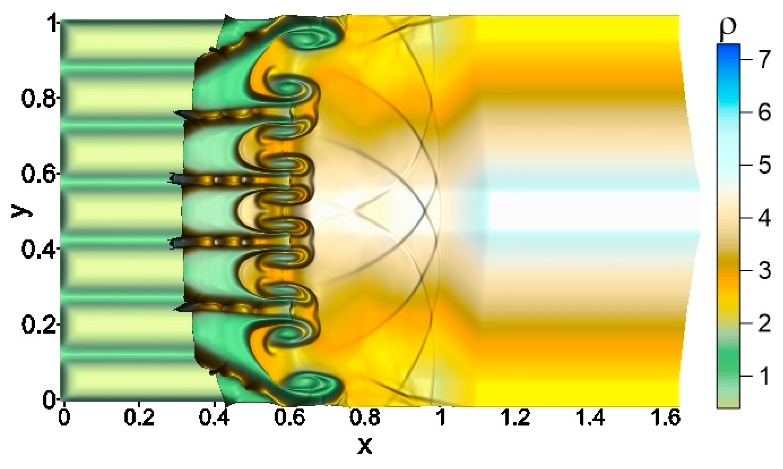
In the simulation specific internal energy, and volume density of kinetic energy, was investigated for the interaction of a thermally stratified energy source with a preliminary plane shock wave of the Mach numbers M = 6, 7, 8, 10, 12. The fields of the parameters are forming as the solution of the 2D Riemann problem describing the interaction of the shock wave with the boundaries of heated layers forming the thermally stratified source. This solution includes a shock wave and contact discontinuity, moving to the left, and a rarefaction wave to the right of them. Here the initial shock wave coordinate was xsw = 1.5 and the stratified energy source boundary coordinate xs = 1.4.
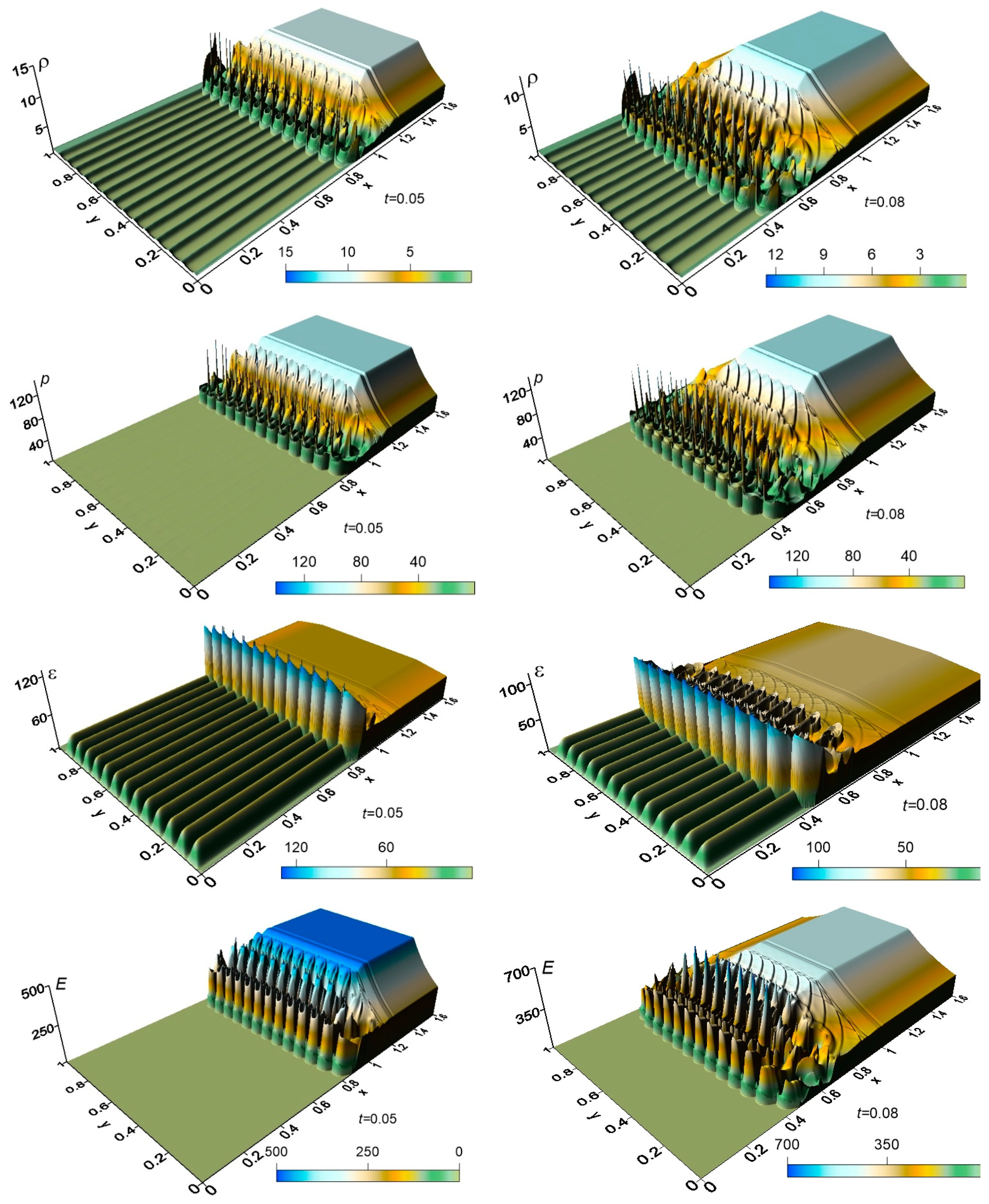
In
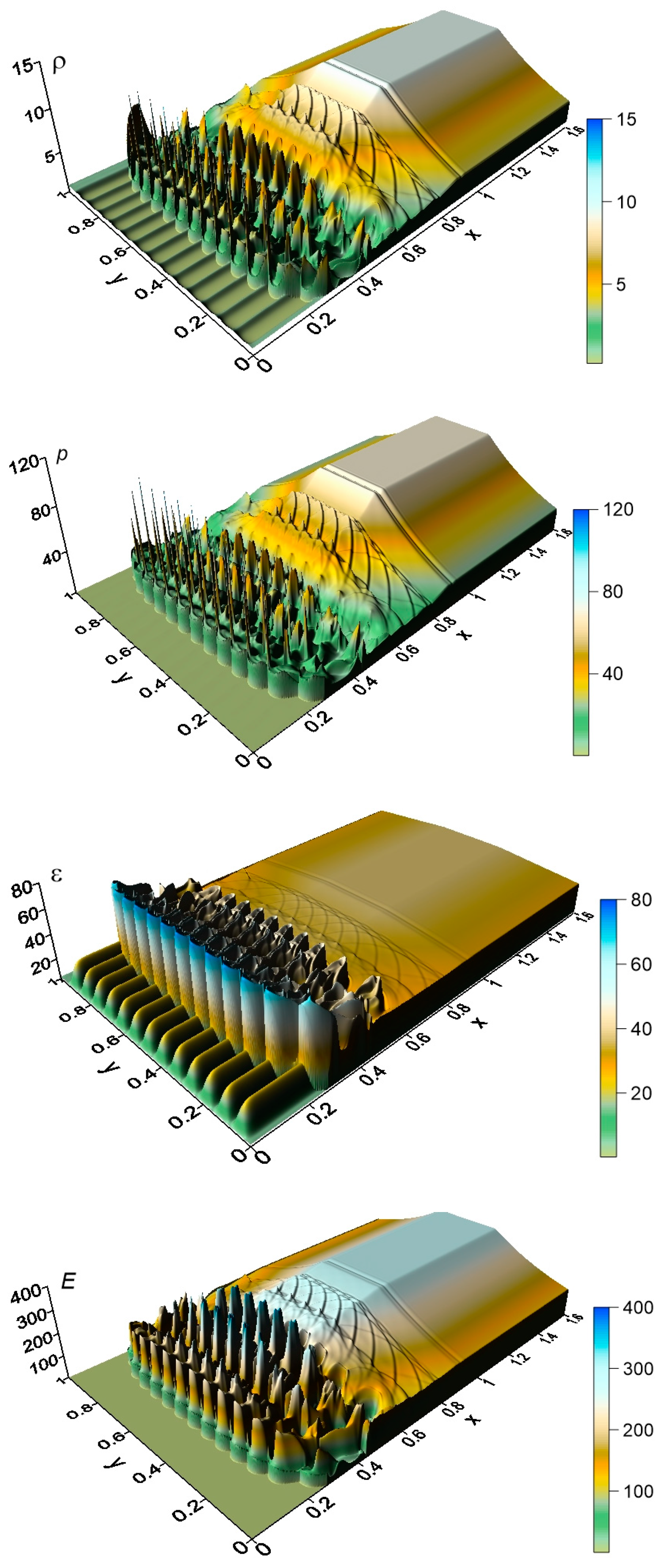
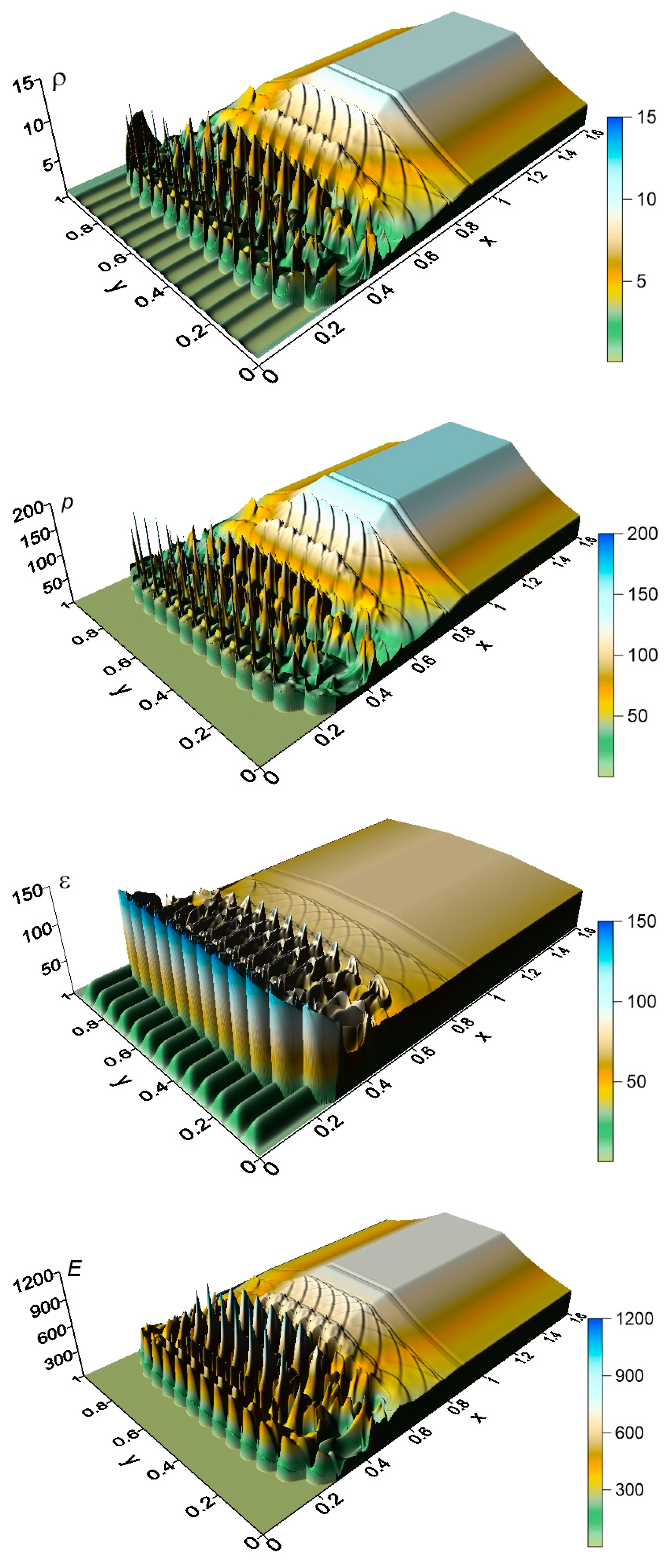
Figure 4 typical flow dynamics resulting from stratified energy source—shock wave interaction is presented. It can be seen that the fronts of the shock wave and contact discontinuity become wavy and complicated flow structure is generated including the manifestation of instabilities. Dynamics of density, pressure and two types of energy fields for the interaction are presented in
Figure 5. Time moments are indicated in the right lower angle in the images. In
Figure 6,
Figure 7,
Figure 8 and
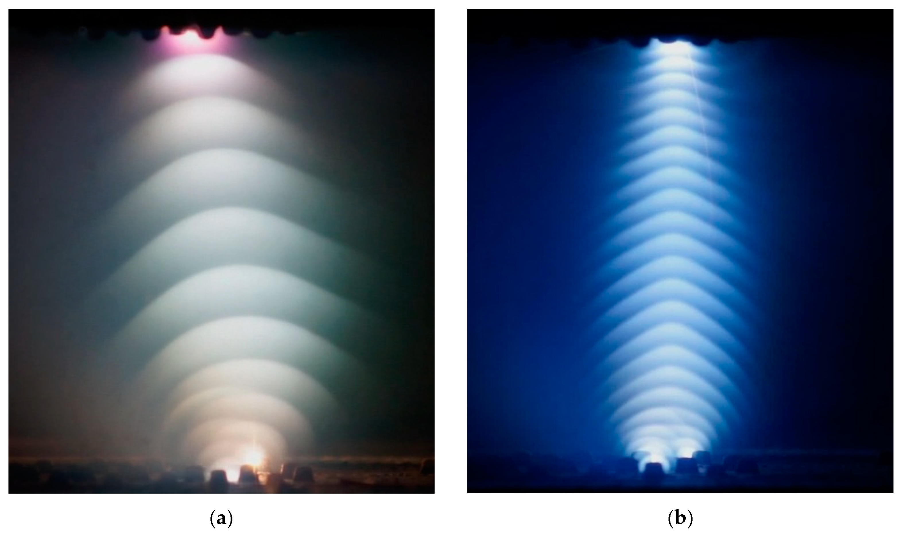
Figure 9 the fields of considered parameters are presented for M = 6, 8, 10, 12, accordingly. The fields for M = 6 correspond qualitatively to the situation of the complete disappearance of the shock front at the schlieren pictures in the experiments described in Part 3 [
24].
The multiple manifestations of the Richtmyer-Meshkov instabilities which are exhibited as local peaks in the density, pressure and kinetic energy fields can be seen (see, also, [
15]). One can see that in the density field the shock wave front is practically disappeared under the action of the multiple generation of the Richtmyer-Meshkov instabilities. This explains the effect of the disappearance of the shock fronts at the obtained schlieren photographs in the case of small-scaled ionization strata—shock wave interaction [
24]. In this experiment, the shock wave completely disappeared in the very beginning of the interaction with the afterglow region, which had a thermally stratified nature. It should be noted that, as calculations have shown, for the Mach numbers under consideration, instabilities manifest themselves in the first microseconds after the start of the interaction process, and at this time the shock wave already becomes wavy and blurred.
It is also important that, at sufficiently high Mach numbers, the density changes behind the shock front are limited. Consequently, the density perturbations arising during the development of instability are also limited.
Nevertheless, it should be underlined that the front of the shock wave doesn’t disappear at all in the fields of other parameters despite the presence of the instabilities. At the same time, this instability does not manifest itself in the internal energy fields. This can be explained by the fact that entropy perturbations, whose propagation velocity is less than the speed of sound, make a significant contribution to the variation of ε near the shock front. Furthermore, one can see a series of acoustic waves emitted by the resulting shock-wave structures with instabilities.
Note that the curvature of the shock wave front is due to the boundary conditions on the horizontal walls and for M = 6 it is in accordance with the front curvature at the schlieren pictures for the case of large-scaled ionization strata—shock wave interaction [
24].
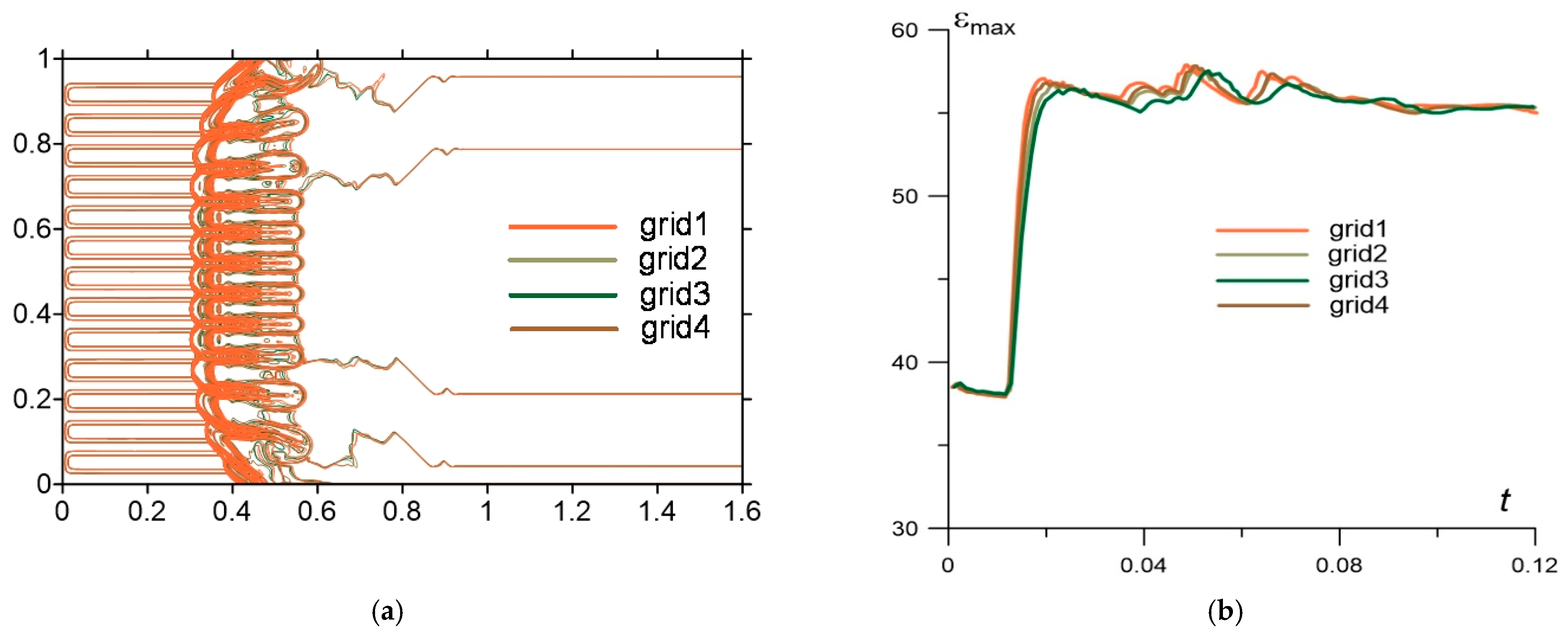
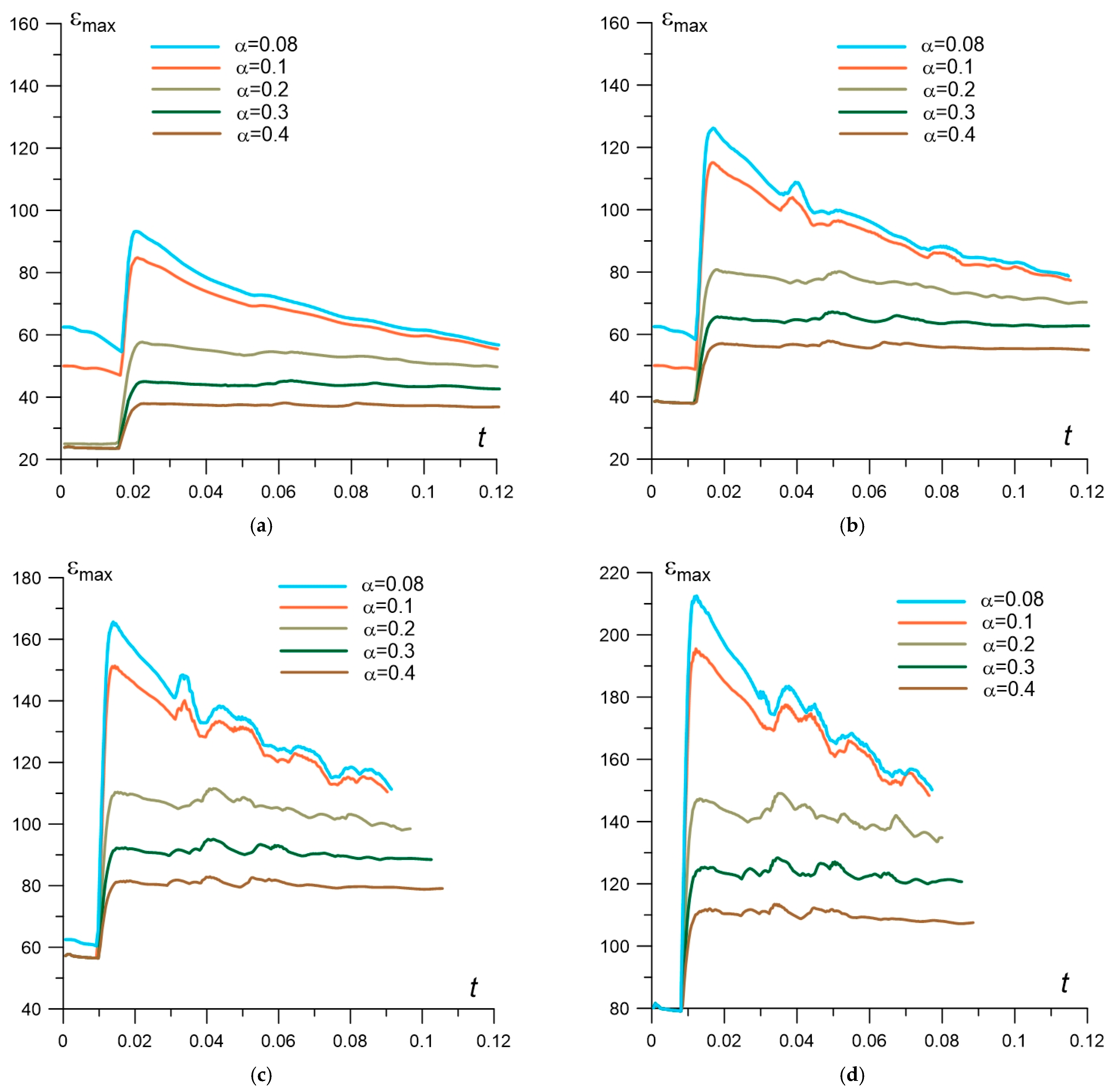
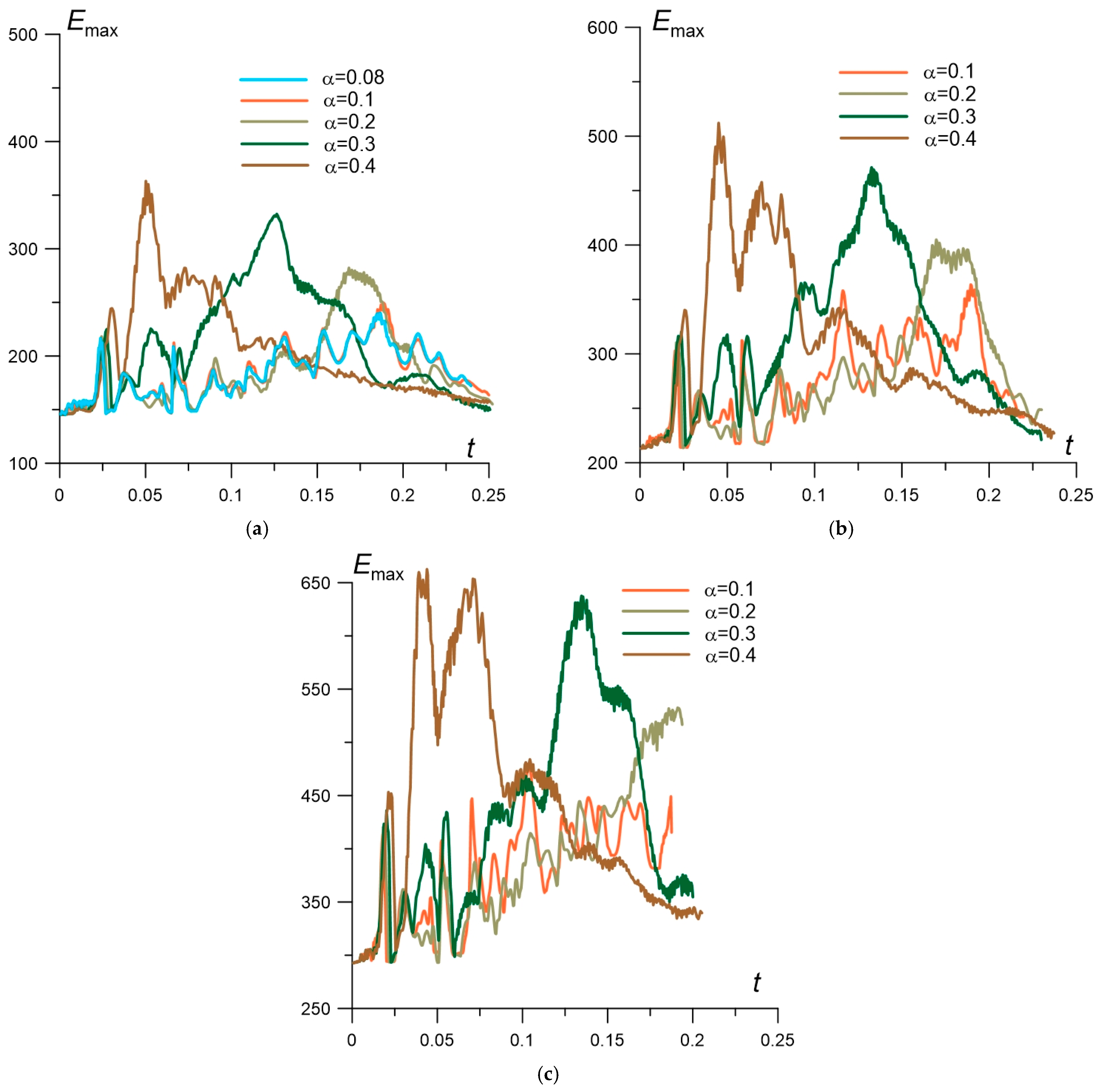
In
Figure 10 the dynamics of maximum value ε
max in the obtained shock-wave structures is presented for different rarefaction parameters α for all considered Mach numbers of the shock wave. Here, the maximum value of the internal energy is calculated over the coordinates in the region of the obtained shock-wave structure with instabilities. This value has a sense of the greatest local increase in the internal energy due to the formation of such a structure as a result of the action of a stratified energy source. It can be seen that these dependences have maxima on
t at the beginning stage of the interaction. These maximum values are larger for smaller α and for larger M.
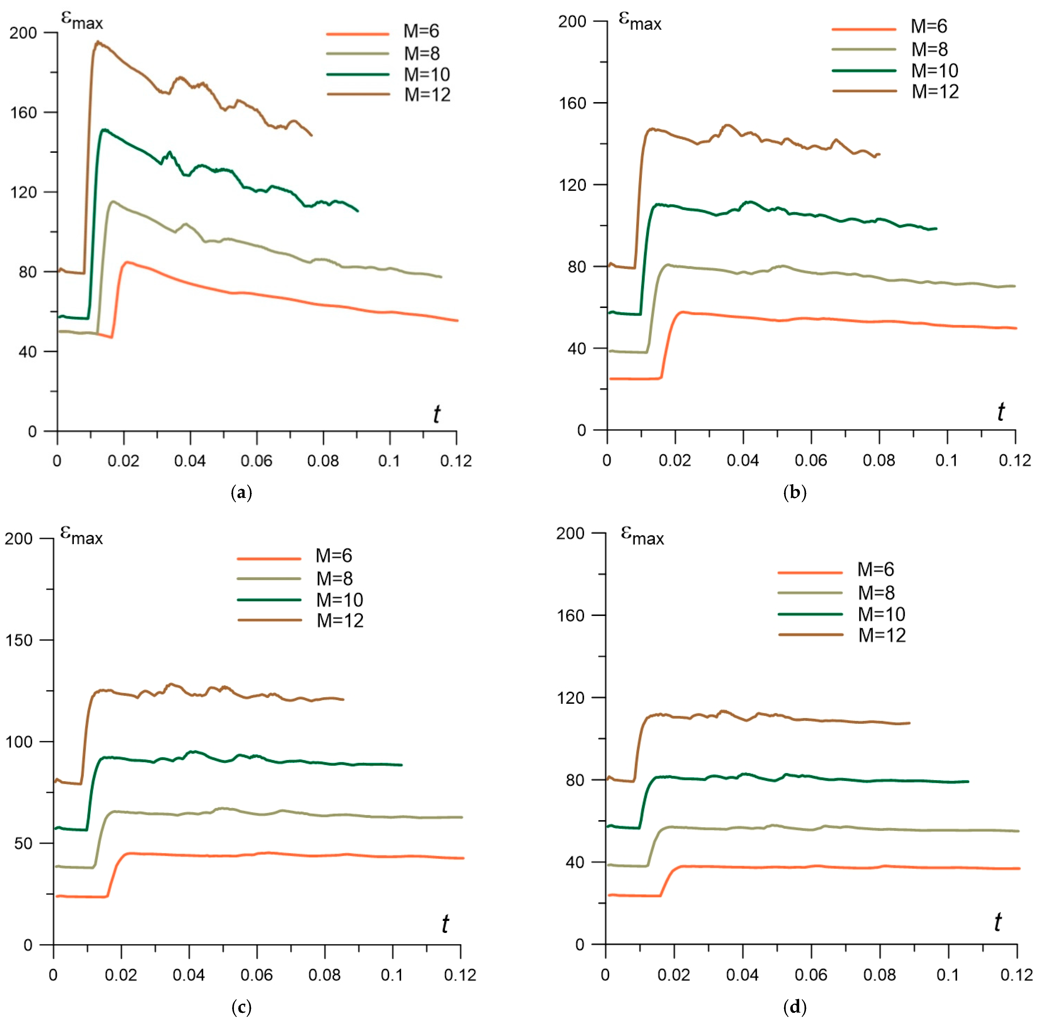
Figure 11 shows these dependencies for different M for all considered α. It can be seen that at the first stage, the dynamics of ε
max is changing stronger for smaller α and larger M. Note that fluctuations in internal energy are directly connected with fluctuations in the temperature of the gas in the flow, therefore, from the results shown in
Figure 10 and
Figure 11, similar conclusions follow for the gas temperature [
25].
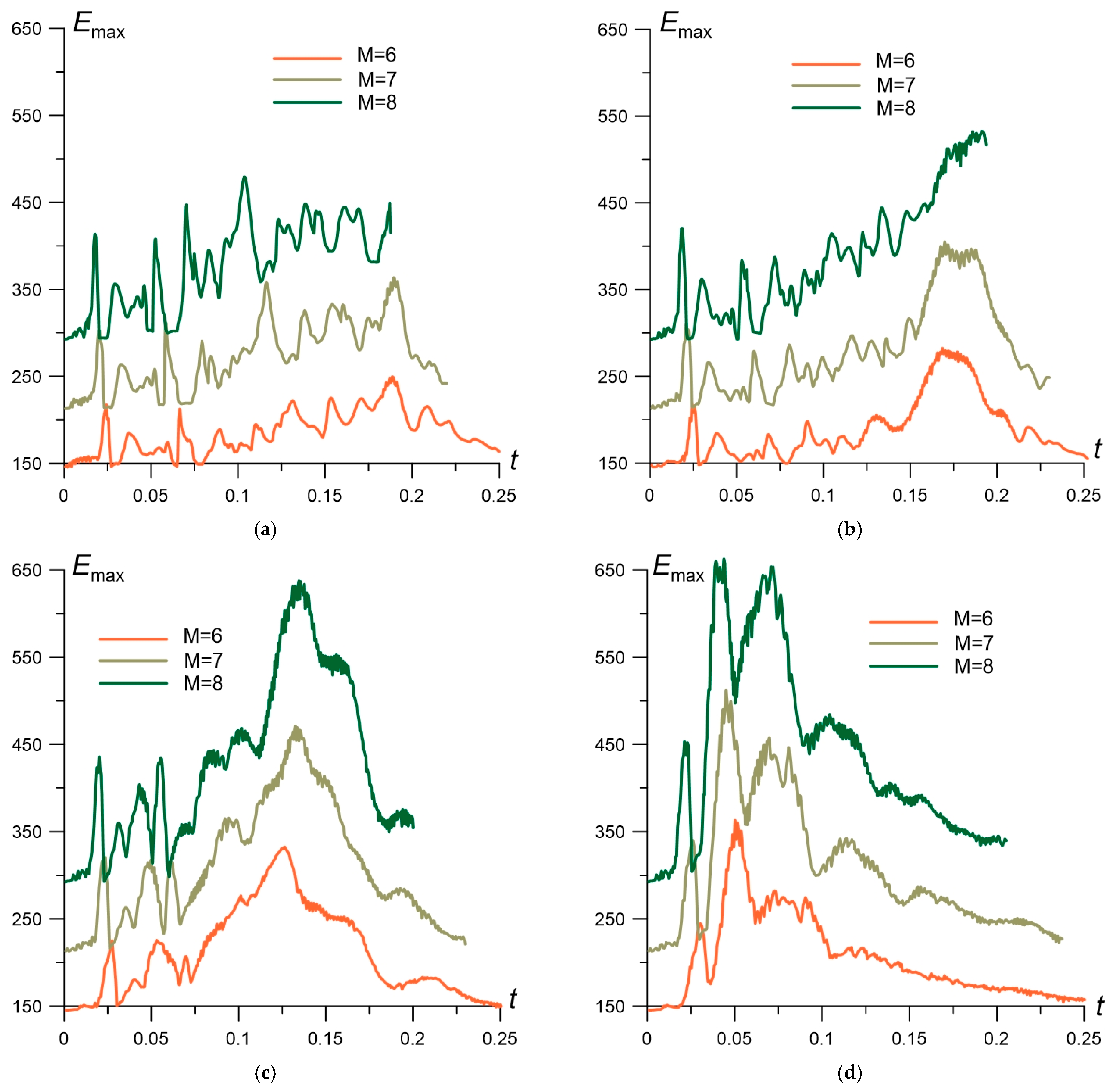
The same analysis is presented in
Figure 12 and
Figure 13 for the dynamics of maximum value
Emax in the obtained unstable shock-wave structures. This value has a sense of the greatest local increase in the kinetic energy due to the formation of a shock-wave structure as a result of the use of a stratified energy source. In
Figure 12, the dependences
Emax(
t) are presented for different rarefaction parameter α for the considered shock wave’s Mach numbers. One can see that the dependences have maxima on
t which are larger for larger α and larger M.
Figure 13 shows these dependencies for different M for all considered α It can be seen from these dependences that the growth of the kinetic energy occurs quicker for larger α and larger M.
Figure 10 and
Figure 11 show that the density, pressure and internal energy fluctuations are stronger at the initial stage of the interaction while the kinetic energy maxima are generated at the middle stage in time (
Figure 12 and
Figure 13). This can be explained by the fact that the kinetic energy maximum is defined not only by the peaks, connected with the unstable nature of the gas density, but by the behavior of the flow velocities. Thus, the kinetic energy has the maximal attitudes of fluctuations when vortices are generating in the flow and the formation of the vortices takes some additional time.
It should be noted that this paper is devoted to the redistribution of energy and both considered types of energy are characterized by possibly achievable maximum values. The histories of their behavior over time are given for these quantities. At the same time, for the internal energy, the considered time interval up to t = 0.12 turned out to be sufficient (since its maximum value is reached at the initial stage in time). Here, the initial shock wave coordinate xsw = 1.5 and the source boundary coordinate xs = 1.4. For the study of kinetic energy, this time interval turned out to be not enough (because its maximum value is reached at the middle stage in time). Here, we used a different geometry of the calculation domain with the position of the shock wave xsw = 2.25 and the boundary of the energy source xs = 2.15 with the same vertical dimensions. This made it possible to study the time history of kinetic energy in the time interval up to t = 0.25 for the considered shock wave Mach numbers.
To evaluate the “energy” efficiency of using a thermally stratified energy source, the fields of parameters for stratified and homogeneous sources were compared. The homogeneous source was defined at the initial time in the form of a homogeneous region of heated gas with the sizes that coincide with the sizes of the stratified energy source. The parameters of a homogeneous energy source were chosen in such a way that the average values of internal energy in the stratified and homogeneous sources were equal:
Here Ni and Nj—the amounts of grid nodes in i- and j-directions, εaveraged and εh averaged are the averaged values of internal energy in the stratified and homogeneous sources, accordingly.
It is easy to conclude that in this case, the values of full energies for these energy sources are also equal (since the velocity components in the energy sources are equal to zero). Thus, as the result, we can evaluate the transformation of different types of energy only due to the redistribution of a source energy into layers.
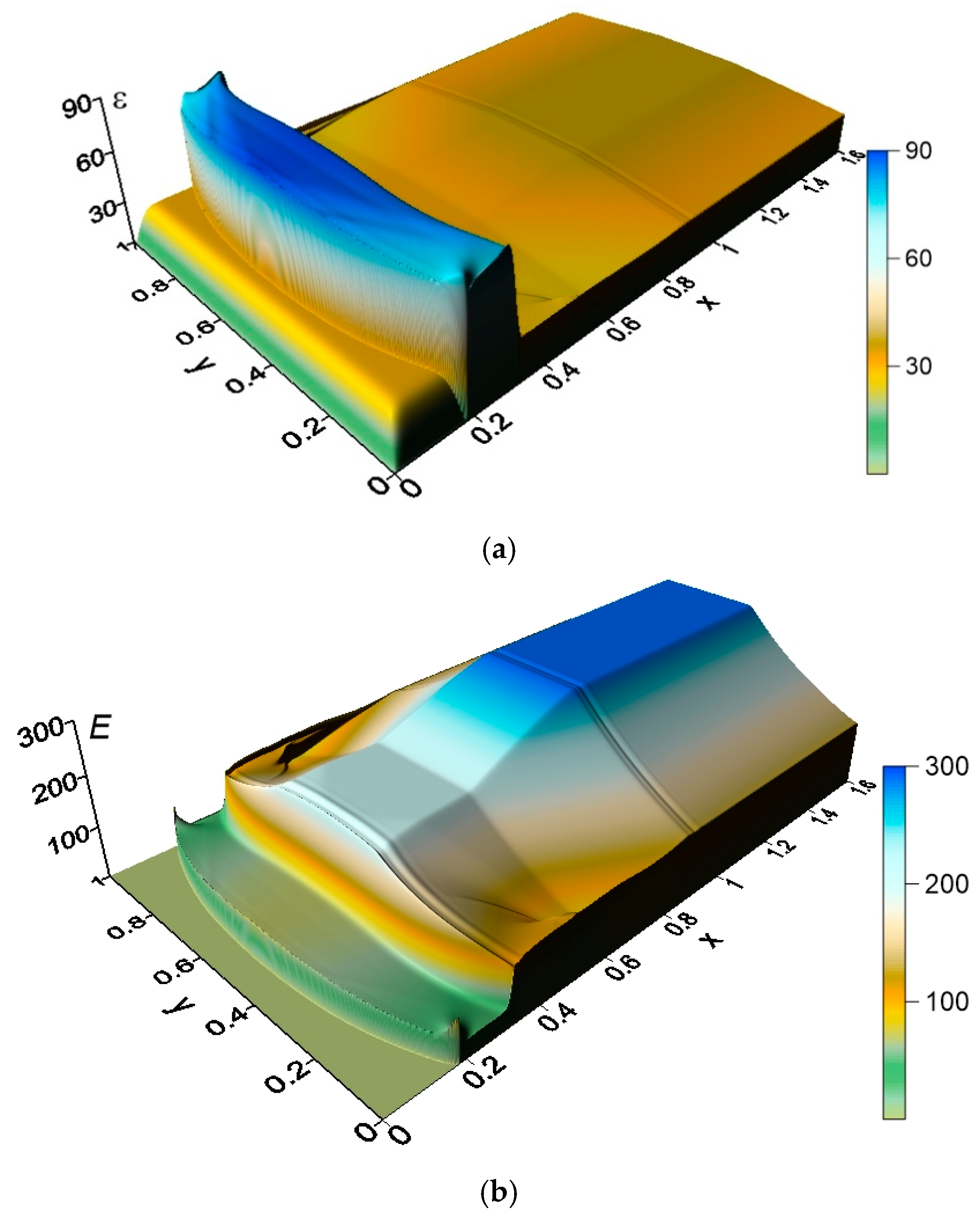
Figure 14 demonstrates typical fields of internal (
Figure 14a) and kinetic (
Figure 14b) energy for the homogeneous energy source (compare with the images for ε and
E in
Figure 7 for the stratified energy source). The fields in
Figure 14 are forming as the solution of the 2D Riemann problem describing the interaction of a preliminary plane shock wave with a heated area produced by the homogeneous source. It is seen that in the region of the shock wave structure under consideration the fields of ε
h and
Eh are close to constant.
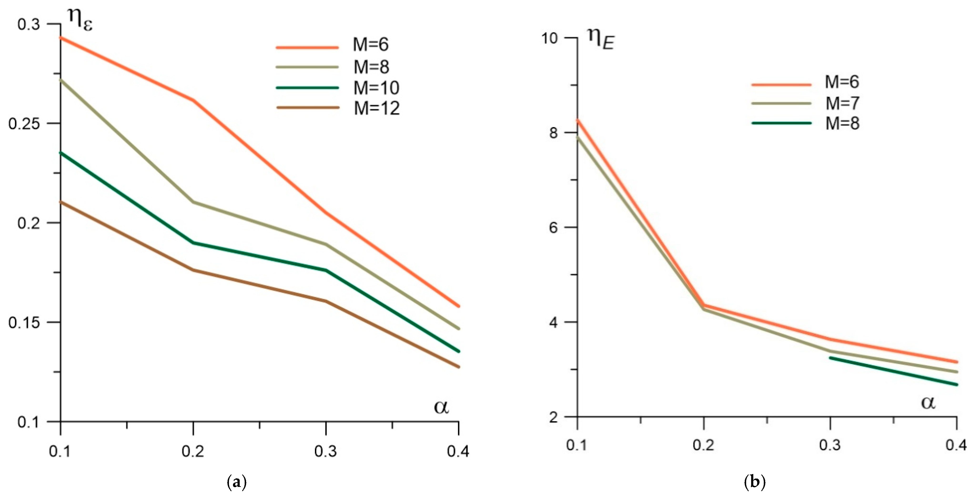
Efficiency in the internal energy η
ε and in the kinetic energy η
E are evaluated as follows:
Here εh and Eh are the values inside the region between the shock wave and contact discontinuity. The values ηε and ηE have the meaning of the maximum relative difference of the considered types of energy over time between their values for stratified and homogeneous energy sources.
In
Figure 15, the dependences of η
ε and η
E on the rarefaction parameter α are presented for the considered Mach numbers. It is seen that the relative deviation in the local peaks of ε can achieve up to 29% (for M = 6, α = 0.1) and increases with decreasing α and M (
Figure 15a). The relative deviation in the local peaks of
E can achieve up to 8.3 times (for M = 6, α = 0.1) and also increases with decreasing α and M (
Figure 15b). It should be pointed out that this value depends on the temperature of the layers in the energy source, more so than on the Mach number of the shock wave. Note that the difference in the behavior of η
ε for M = 6 and for M = 8–10 is connected with a different location of the maximum value ε
max in the considered shock-wave structures.


