Design, Implementation, and Operation of a Small Satellite Mission to Explore the Space Weather Effects in LEO

 , , , , , ,
  , add
Show full author list
, add
Show full author list
Abstract
:1. Introduction
2. Materials and Methods: Ten-Koh Mission Description
2.1. Ten-Koh Project Objectives
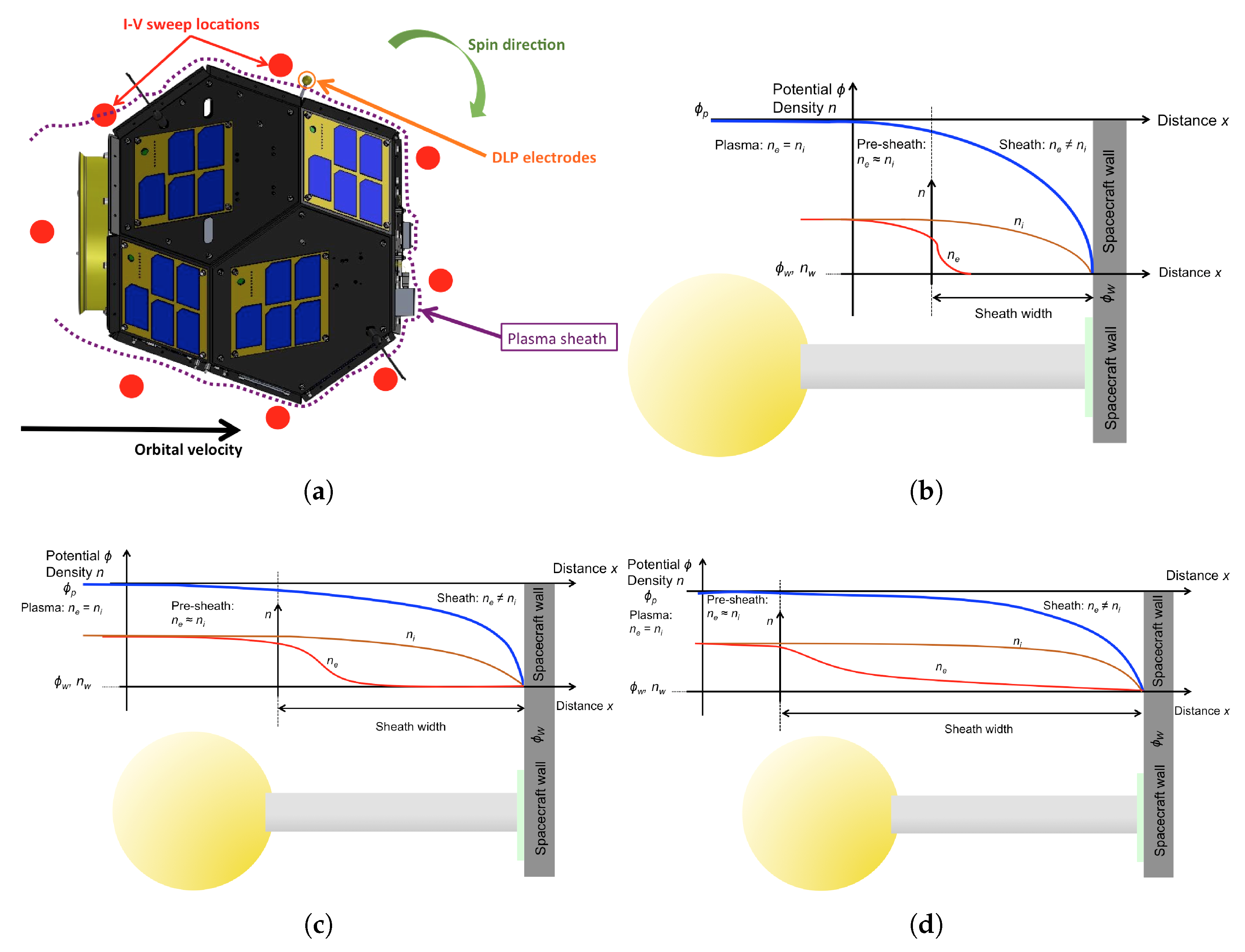
- To characterize the plasma environment around a spinning spacecraft.
- To detect MeV-range electrons in LEO and investigate the space environment in the presence of an extreme low solar activity.
- To investigate the change of physical properties of LATS (Lightweight Ablator series for Transfer vehicle) and CFRP (Carbon Fiber Reinforced Polymer) material samples exposed to the space environment.
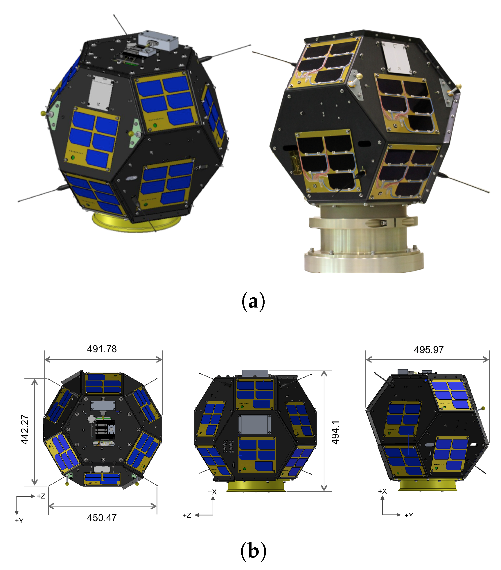
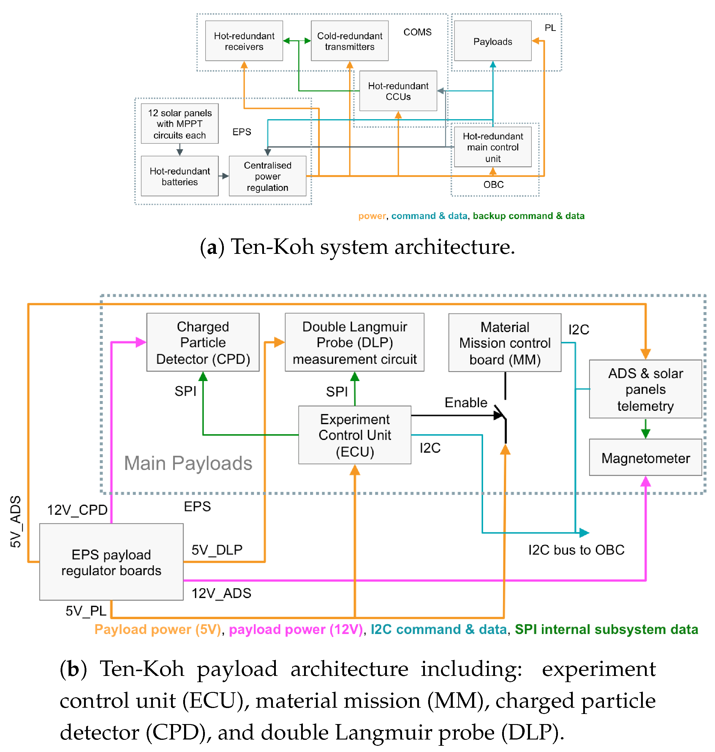
2.2. Satellite Platform
- OBC—on-board computer and data handling subsystem;
- COMM—communication subsystem;
- EPS— electrical power subsystem; and
- ADS— attitude determination subsystem.
2.2.1. OBC
2.2.2. COMMS
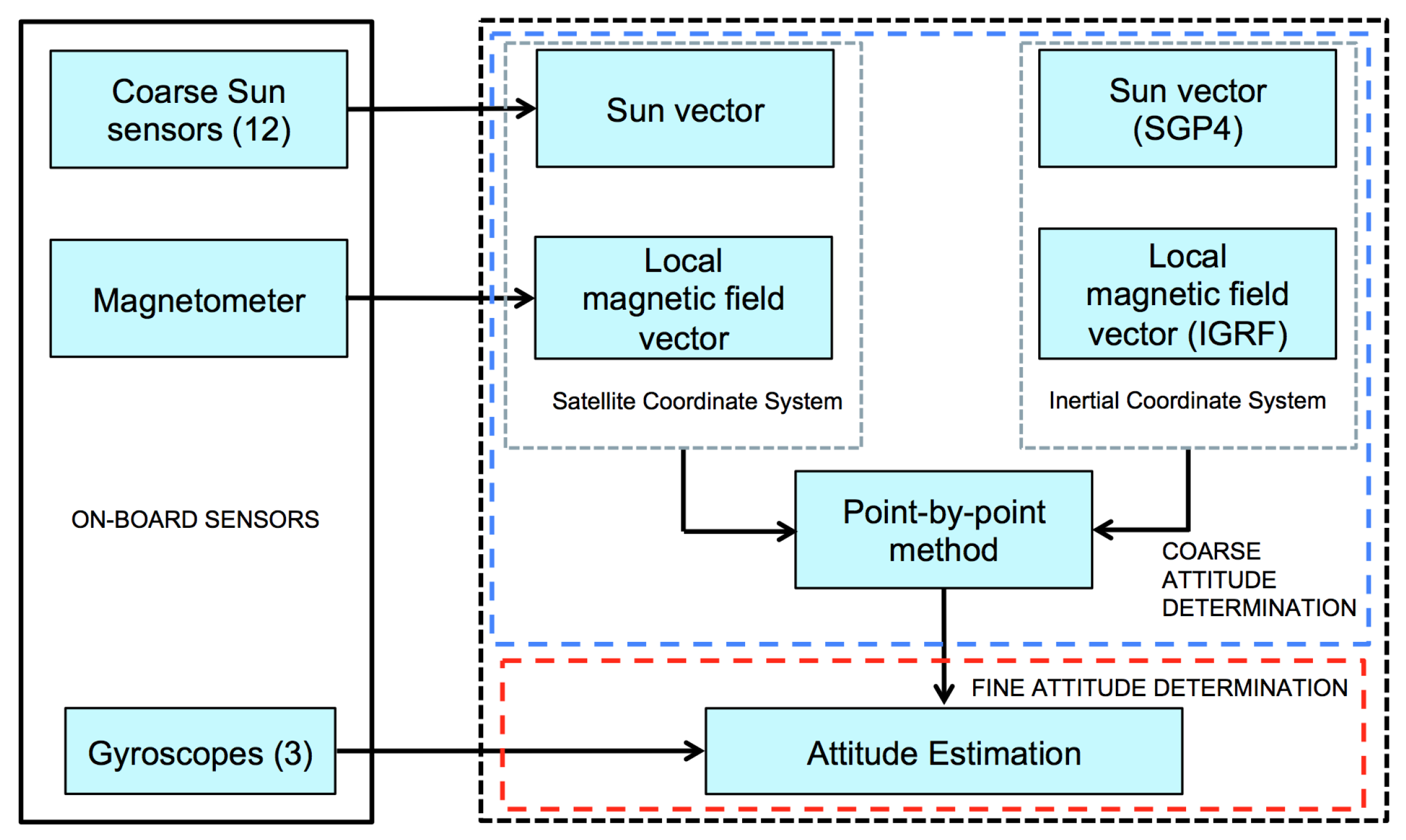
2.2.3. ADS
2.2.4. EPS
- Two independent 5 V lines for the payloads—one for the experiment control unit, ECU and one for the double Langmuir probe, DLP.
- One 12 V line for the charged particle detector (CPD) instrument.
- One 12 V line for the magnetometer instrument.
- Two 5 V lines, one for each of the redundant communications subsystems.
- One 5 V line for the attitude determination subsystem (ADS) and all solar panels telemetry acquisition circuits.
- One 5 V line for the entire EPS subsystem.
- One 5 V line for the OBC subsystem.
- Material mission (MM): 4.8 W.
- Charged Particle Detector (CPD): 8.8 W.
- Double Langmuir Probe (DLP): 5.5 W.
- Attitude Determination Subsystem (ADS): 5.5 W.
- Thermal Switch (TSW): 5.5 W.
- Ultracapacitor (UCP): 5 W.
2.3. Payload
- Sample 1: CF/PEEK with no coating.
- Sample 2: CF/PEEK with a special coating (silsesquioxane) to protect against atomic oxygen.
- Sample 3: CF/PEEK with a special coating (yttrium oxide) to protect against UV.
- To increase the spatial and temporal localization of other payload measurements.
- To investigate the GNSS signal disruption, total or partial, due to ionospheric varying conditions.
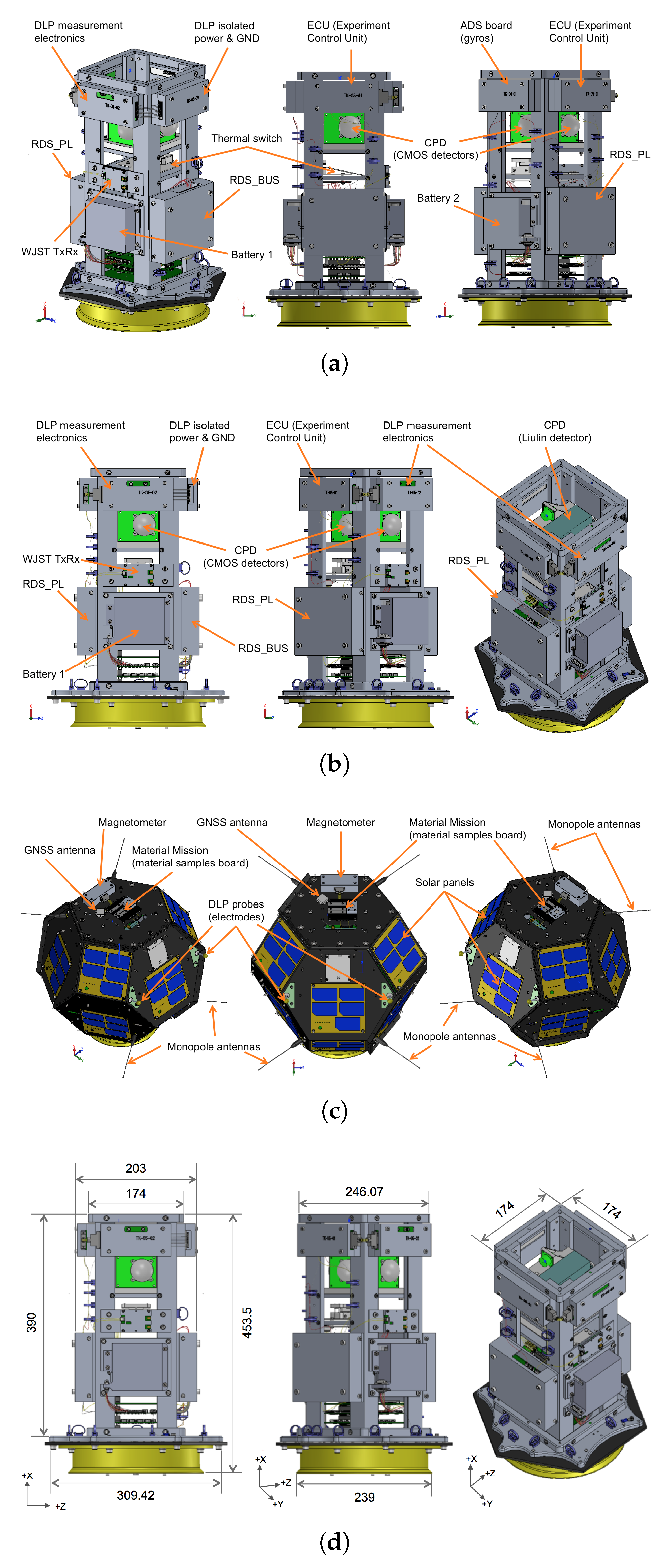
2.4. Ten-Koh General Arrangement
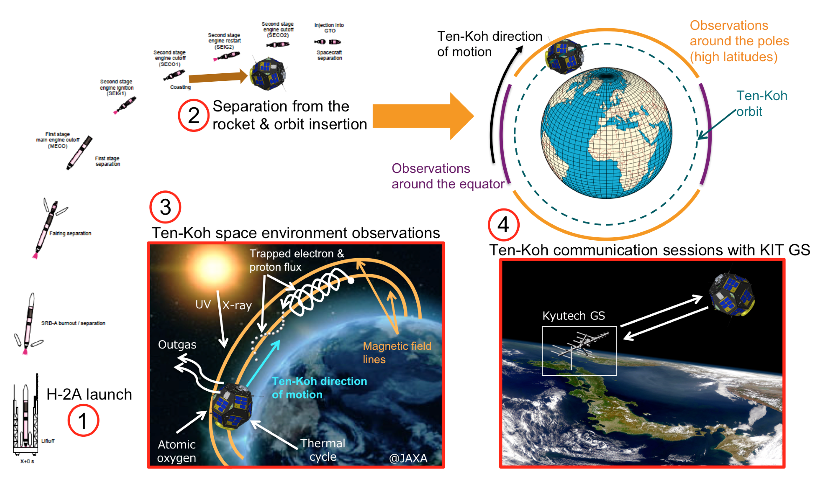
2.5. Satellite Concept of Operations
- Launch on 29 October 2018 at 13:10 Japan Standard Time (04:10 UTC) from the Tanegashima Space Center in Japan, onboard the H-2A rocket number F40 as a piggyback payload of the GOSAT-2 satellite.
- Separation from the rocket 2000 s after liftoff at an altitude of 623 km and with an orbital velocity of 7.5 km/s. The preliminary orbit was estimated to plan tracking of the satellite during the first hours after separation, until a more precise ephemeris was obtained later: semi-major axis of 6969.772 km; eccentricity of 0.002586; inclination of 97.835 deg; argument of perigee of 27.546 deg; longitude of the ascending node of 313.285 deg; and true anomaly of 212.990 deg. All data were provided by the Japan Aerospace Exploration Agency (JAXA) prior to the launch [22]. Nominal operations were carried out using Two Line Element sets (TLEs), as customary for small satellites.
- After the separation and orbit insertion, and once all systems onboard were verified, the mission operations started on 19 November 2018.
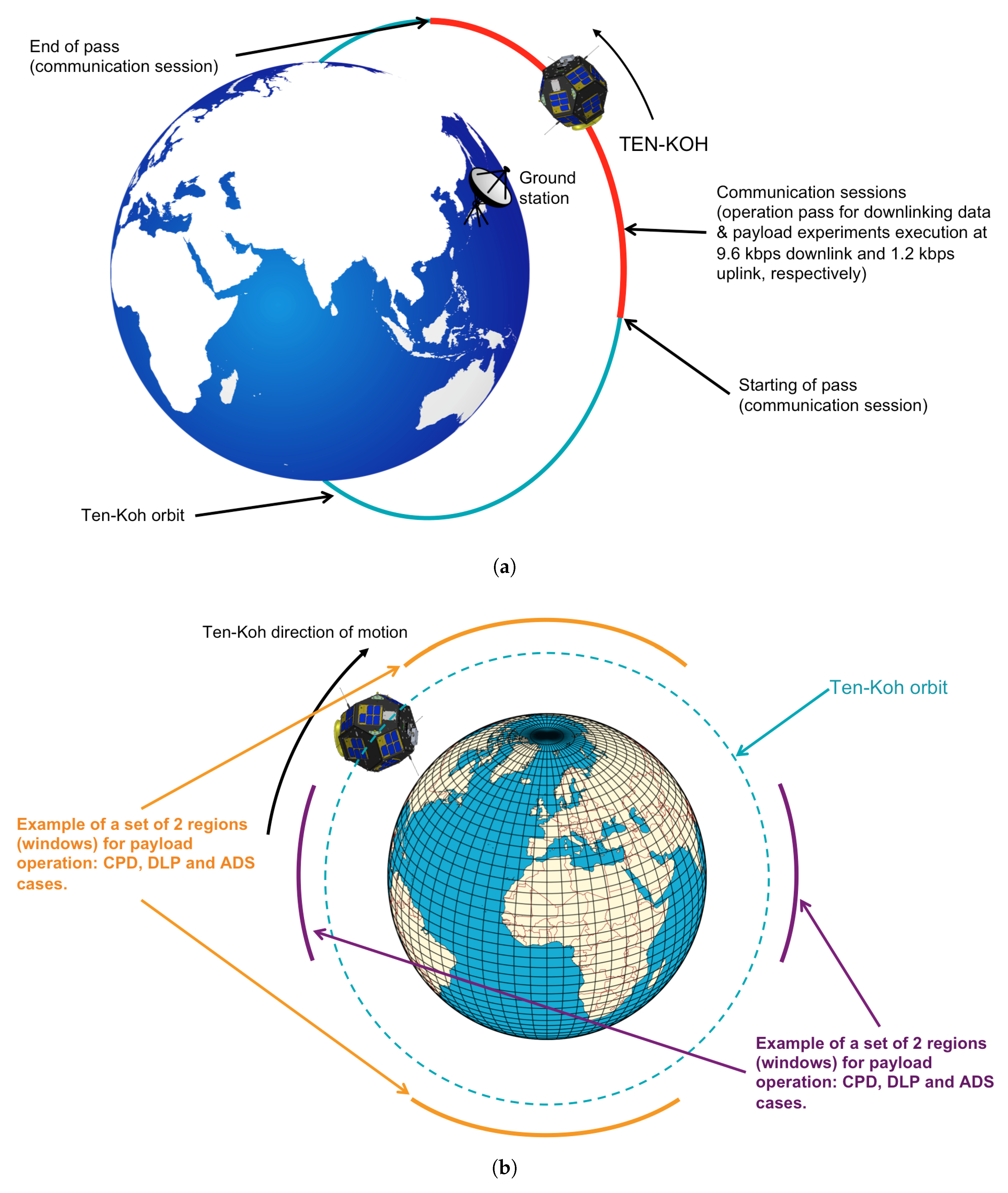
- During each communication session with the main ground station located in Kyutech, housekeeping telemetry and mission data are downlinked and missions are executed according to a previous plan (see the following process of mission planning and execution in Steps A–D).
- A
- An experiment is planned to be executed in a selected position and epoch along the orbit with a specified time duration.
- B
- A set of uplink commands is configured and scheduled for commanding the satellite in a selected pass over the MGS in Japan.
- C
- During the designated pass for operations, the satellite health status is confirmed first by housekeeping telemetry. Then, the uplink command is received by the satellite and the OBC configures the payload instruments and the required subsystems to provide the resources for the mission to be executed.
- D
- The mission experiment is executed and the housekeeping and missions data are stored in different memories on-board the satellite to be downlinked during the next passes over the MGS.
2.6. Design of Mission Operations
- Perigee: 593 km.
- Apogee: 615 km.
- Inclination: 97.8 degree (retrograde orbit).
- Semimajor axis: 6975 km.
- Orbital period: 96.6 min.
- Eclipse duration: 47.7 min.
- Number of revisit times per day over Kyutech (Japan): 4.
- Revisit cycle: 9 days.
- Local equator crossing time of descending node: 13:00 h.
Satellite Operation Modes
- LEOP mode (1).
- Communication sessions mode (4).
- Telemetry mode (4).
- Real-time mode (4).
- Normal mode (2).
- Payload operation mode (3, 4).
- Satellite log mode (4).
- Direct command mode (4).
- Set SD card saving data address mode (4).
- CPD: measurements of CPD are sampled and stored it in the ECU’s SD card.
- DLP: measurements of DLP are sampled and stored it in the ECU’s SD card.
- MM: measurements of MM are sampled and stored it in the MM’s SD card.
- ADS: measurements of ADS (magnetometer, gyroscopes and Sun sensors) are sampled and stored it in the ADS controller’s SD card.
- UCP experiment: measurements of UCP are sampled and stored it in the UCP’s SD card.
- Thermal switch: measurements of the thermal switch are sampled and stored it in the UCP’s SD card.
2.7. Challenges Faced during the Project
2.7.1. Available Generated Power
2.7.2. Available Space Location, Mass and Structure Interface for Some Payload Instruments
2.7.3. Amount of Data Generated by the Mission Instruments
2.7.4. Structure Design Heritage
2.7.5. Attitude Determination and Control vs. Attitude Determination
2.7.6. COTS Design Heritage From Previous Missions
2.7.7. Magnetic Measurement System With No Deployable Boom
2.7.8. Launch Date Fixed by JAXA
3. Results
3.1. Ground Tests
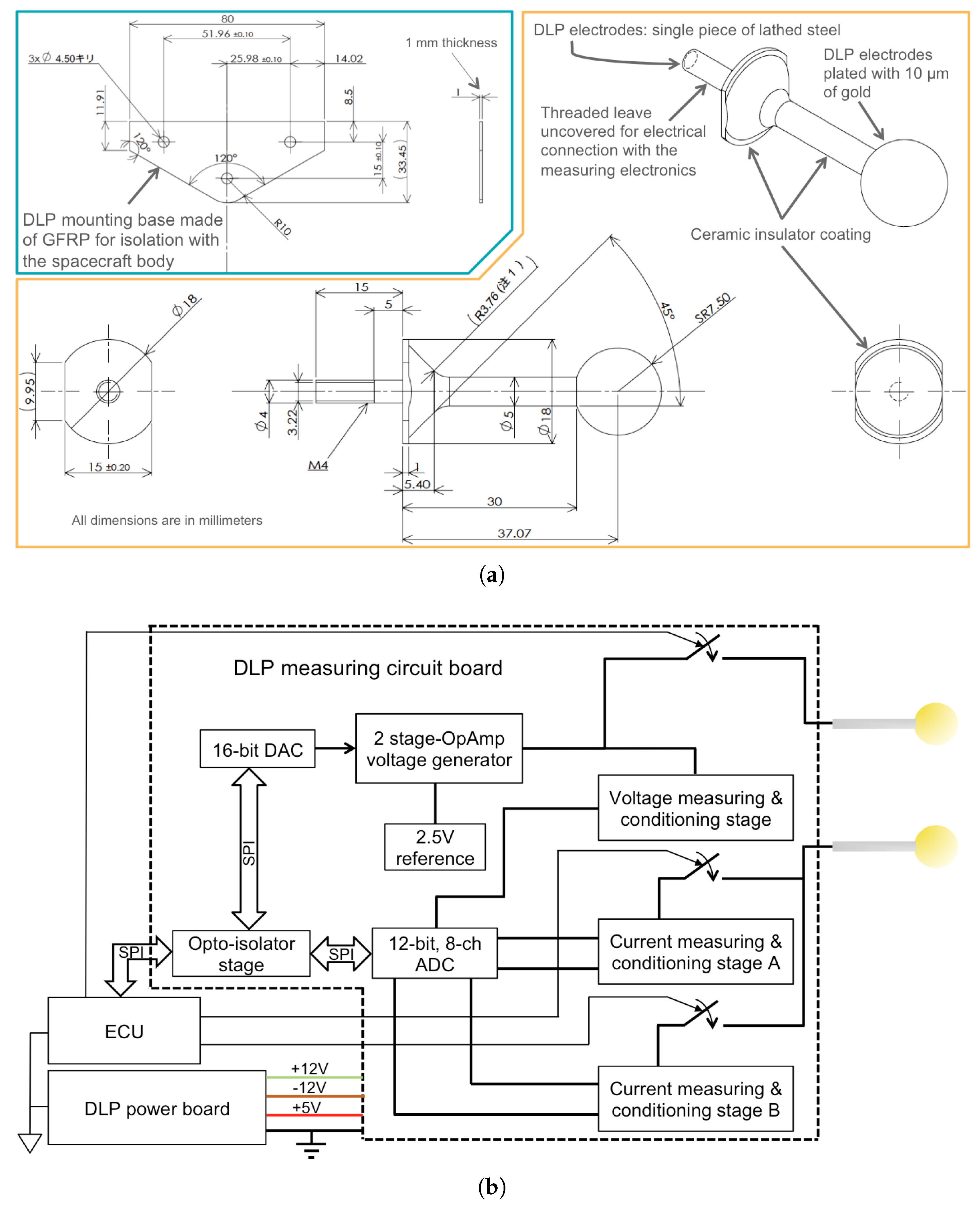
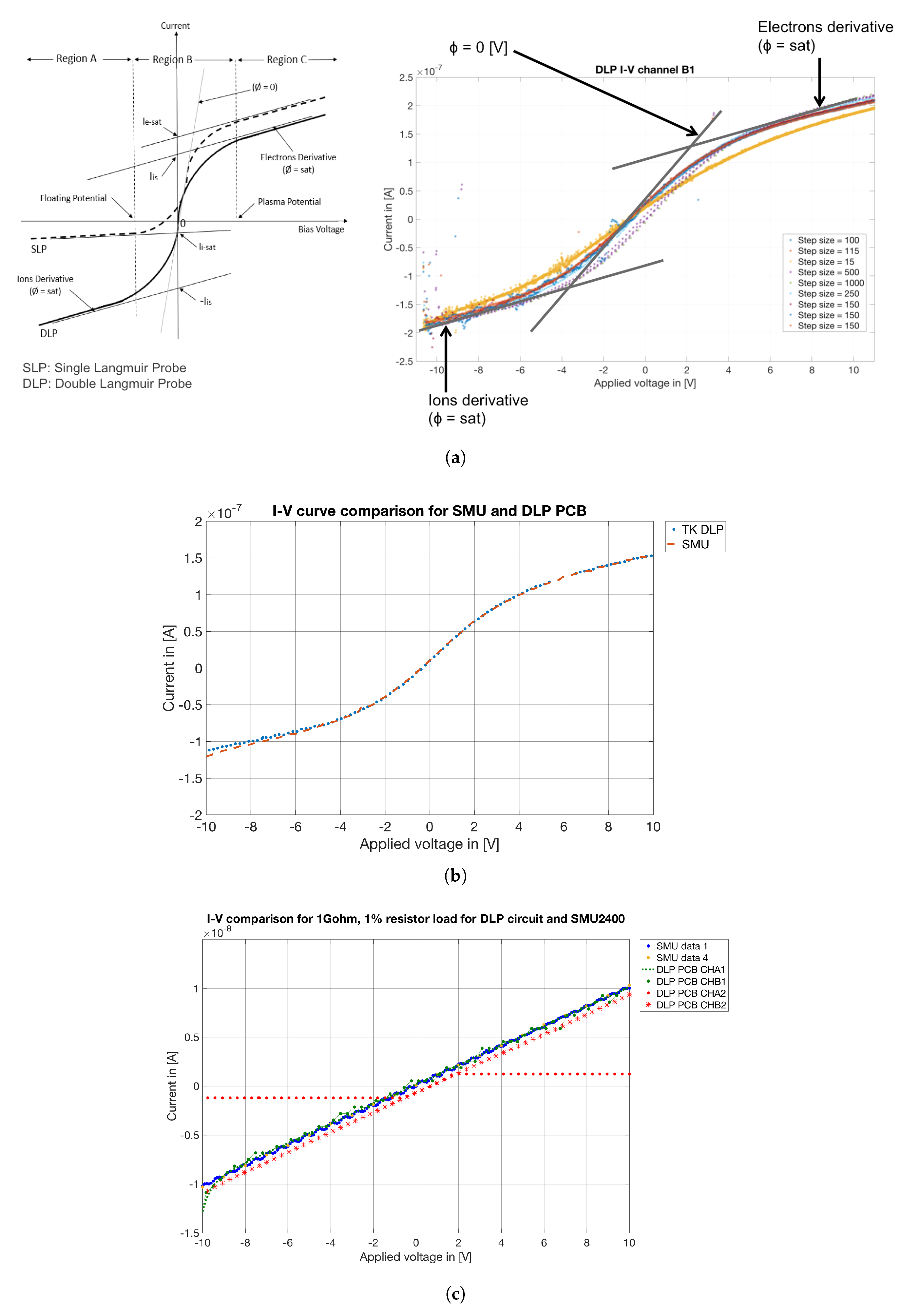
Double Langmuir Probe (DLP)
- Resolution: The number of samples for each I–V sweep can be a set of up to 16 bits voltage increments. Three exemplar cases are presented in Table 4—different resolutions can be implemented depending on the satellite rotation conditions.
- Biasing voltage range: The biasing voltage range can be selected from −10 to +10 V (default), or be any other combination in that range. The only constraint is that the biasing voltage always goes from the most negative value to the most positive one.
3.2. In-Orbit Results
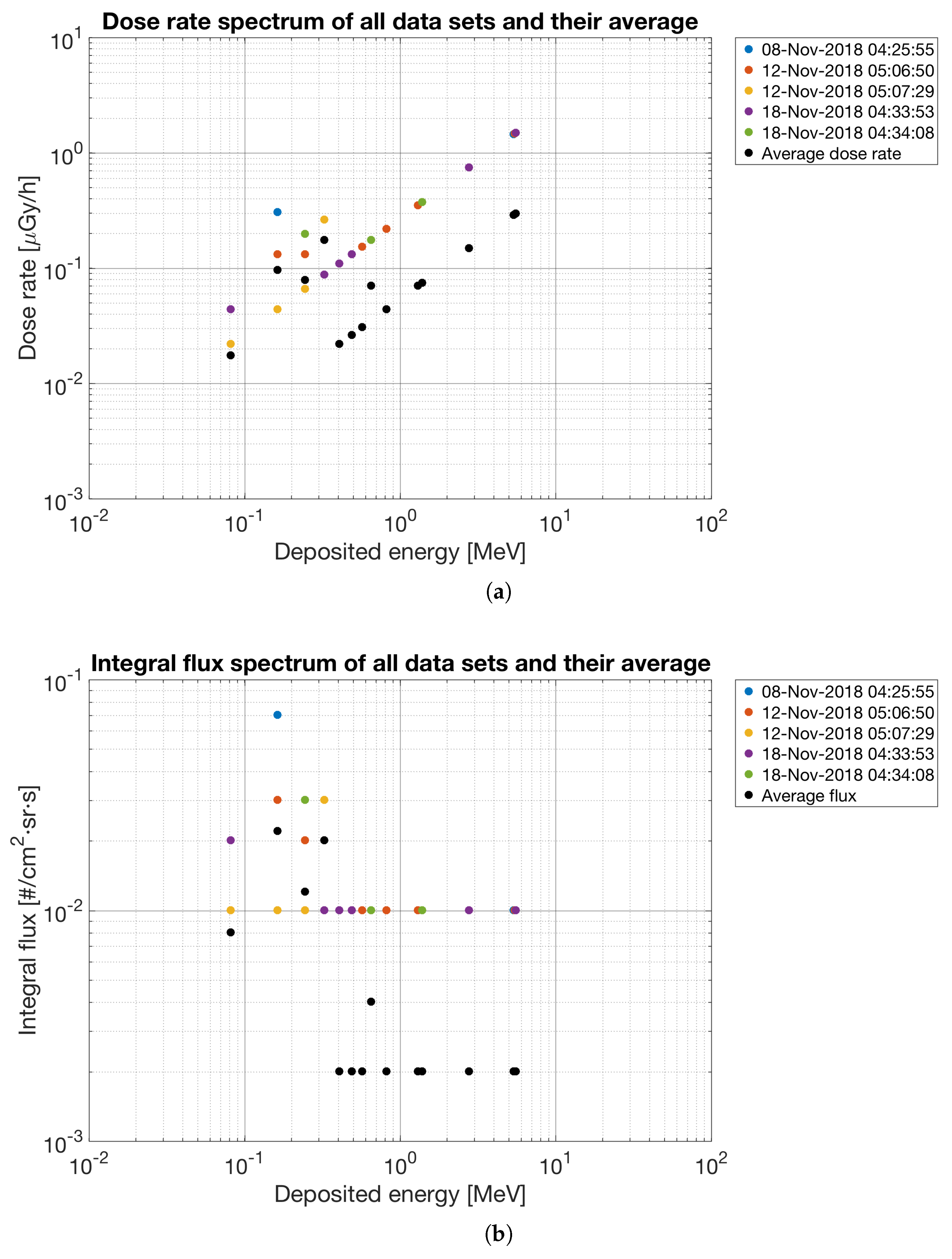
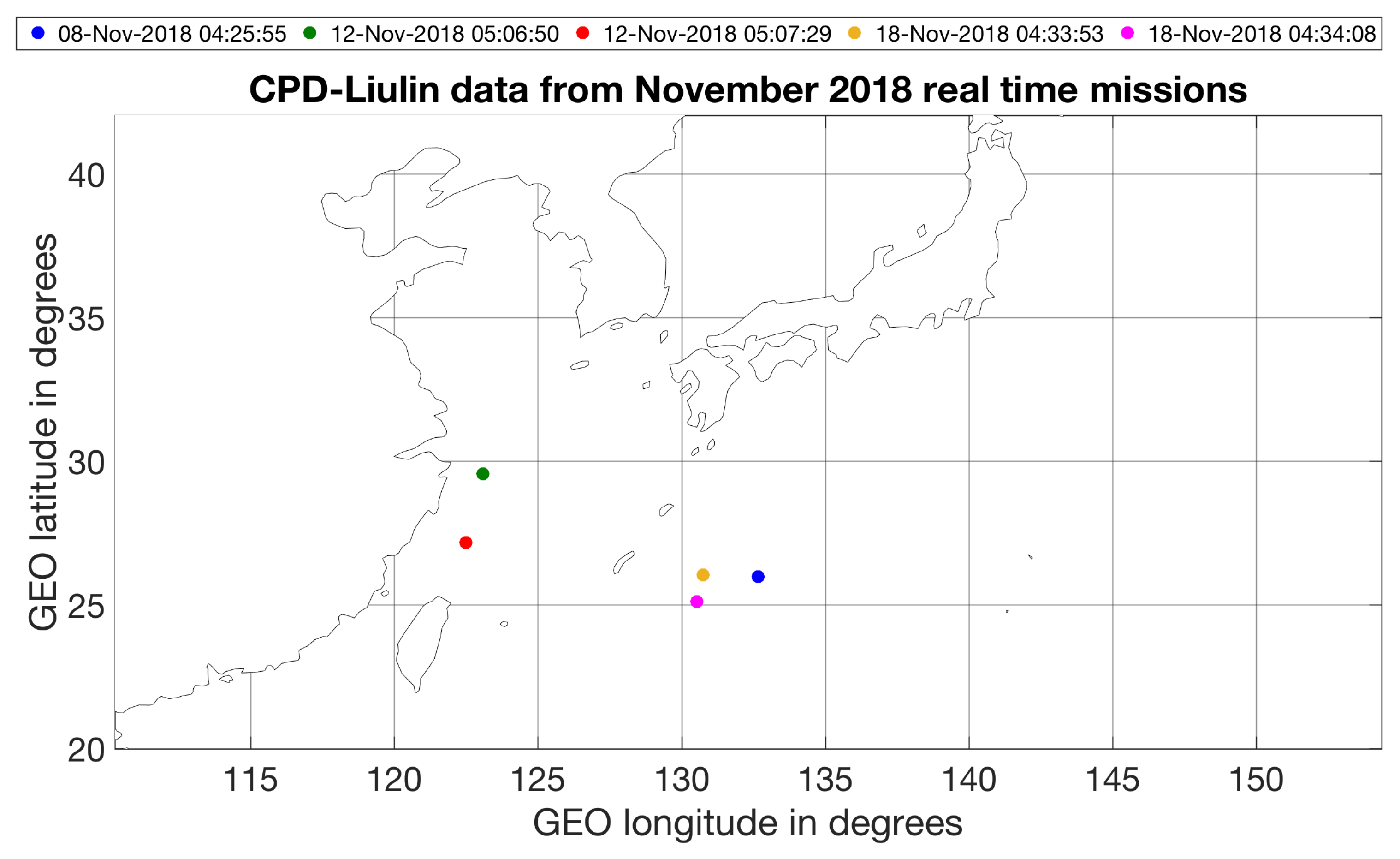
3.2.1. CPD Instrument
3.2.2. DLP Instrument
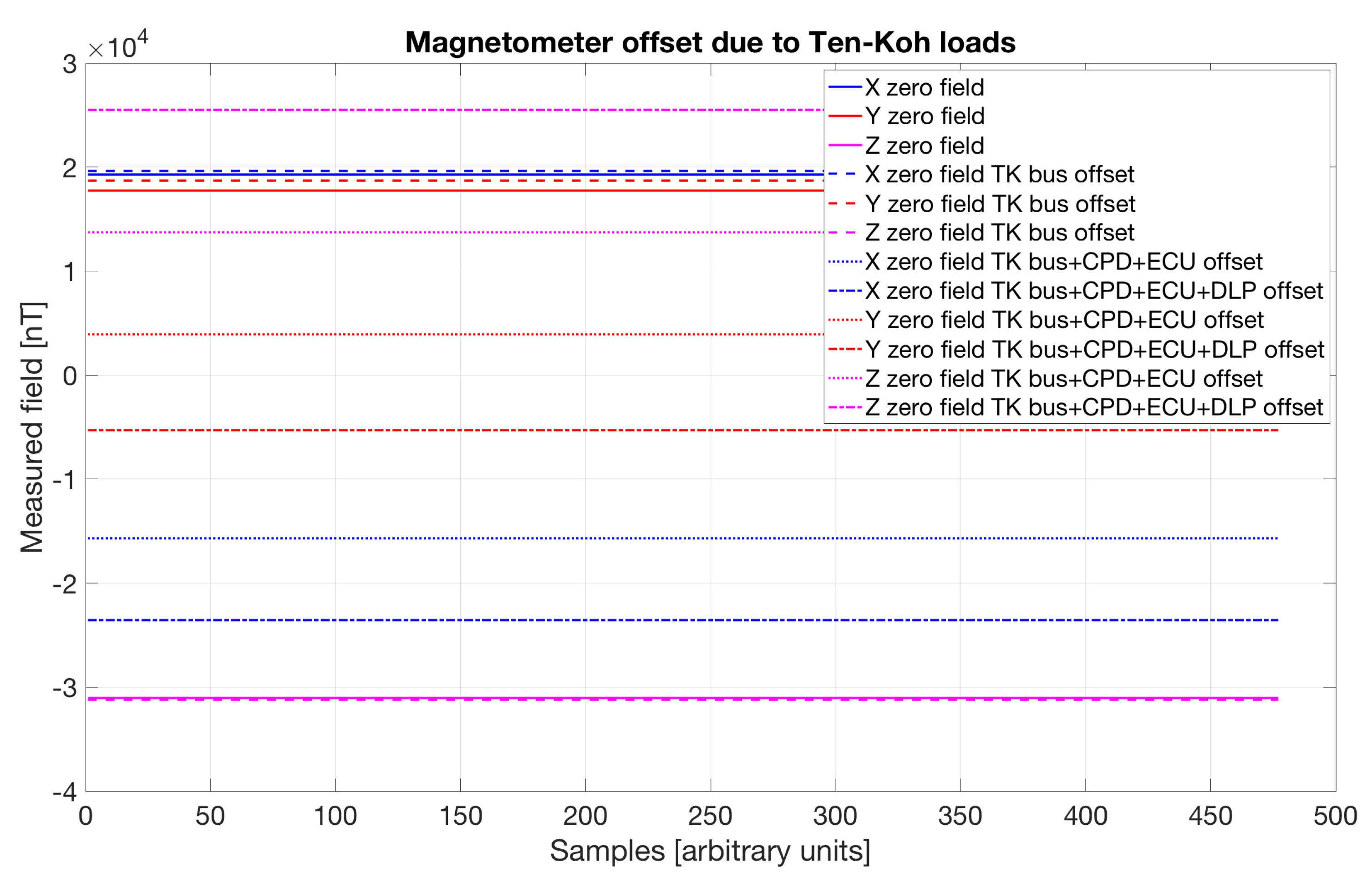
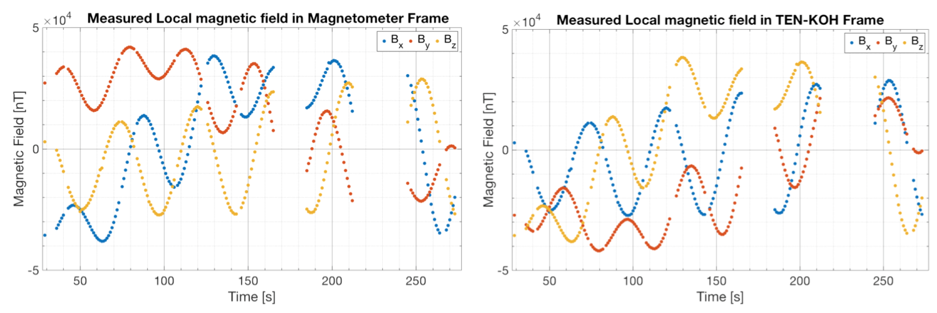
3.2.3. Magnetometer
3.2.4. Material Mission (MM)
4. Discussion
4.1. On-Orbit Operations History
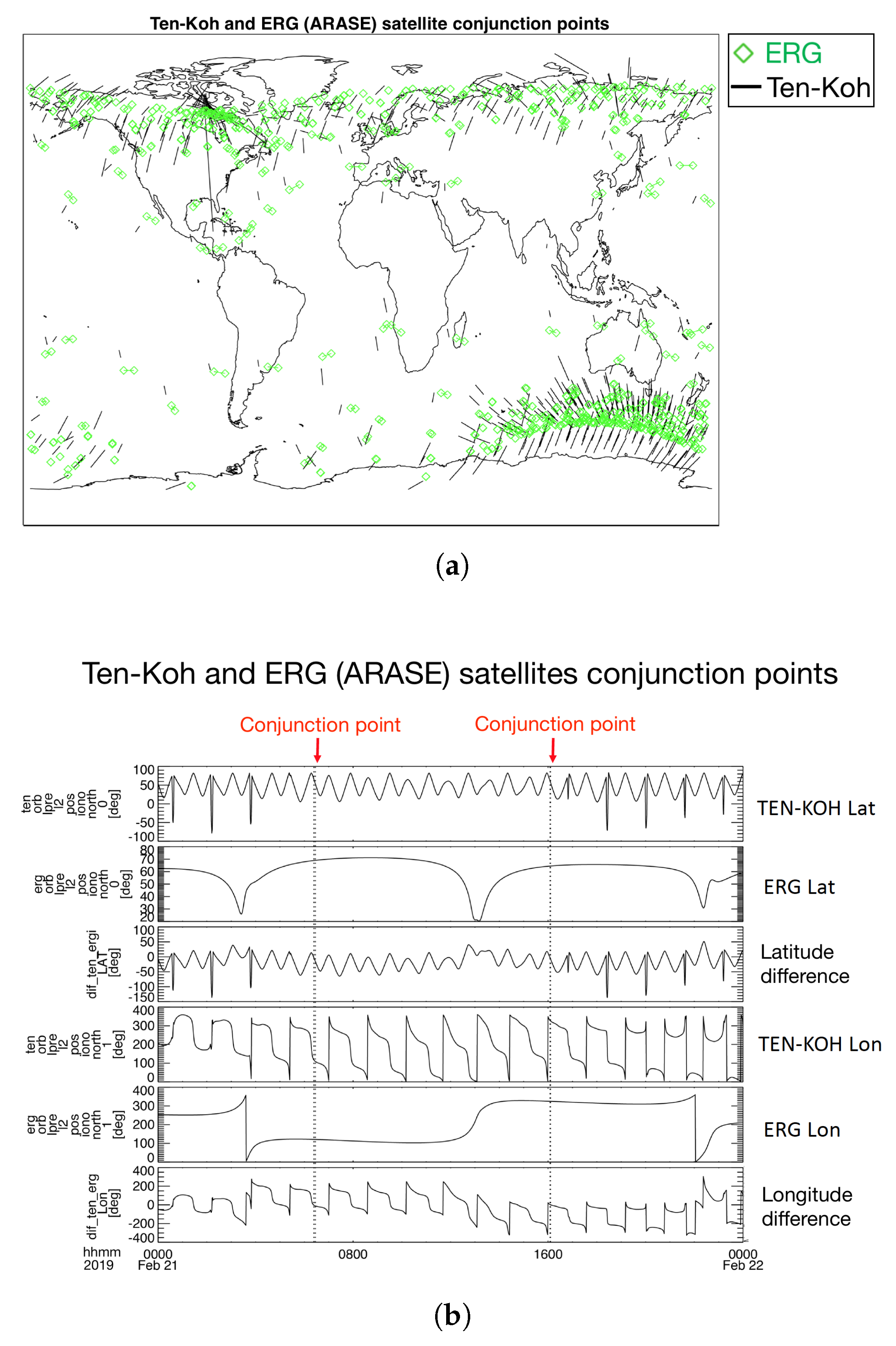
CPD and ARASE Coordinated Observations
4.2. Mission Operations Issues and Status
4.2.1. CPD Operation
4.2.2. DLP Failure
4.2.3. SD Card and Magnetometer Readings Failure
4.2.4. OBC EEPROM Errors
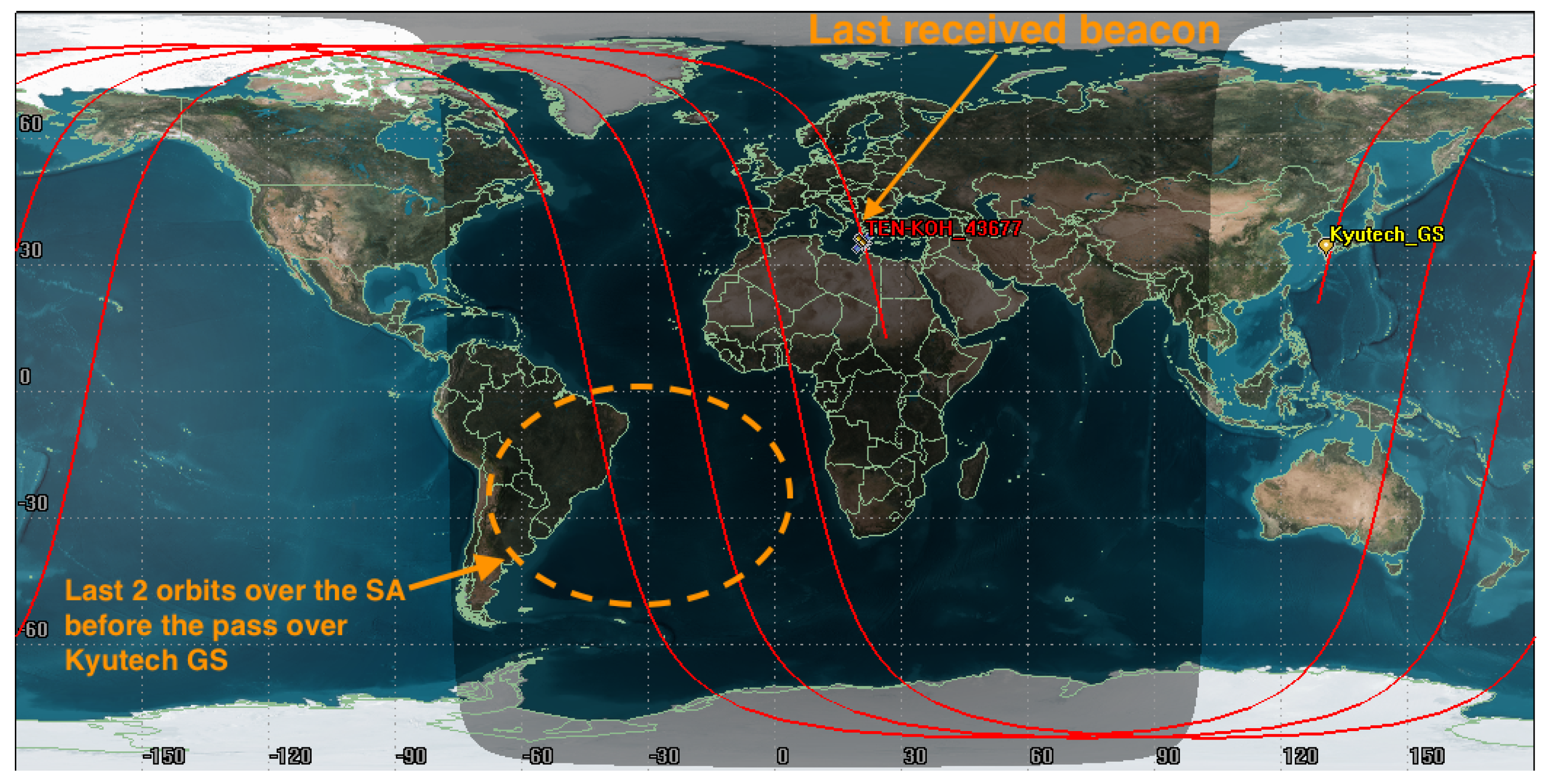
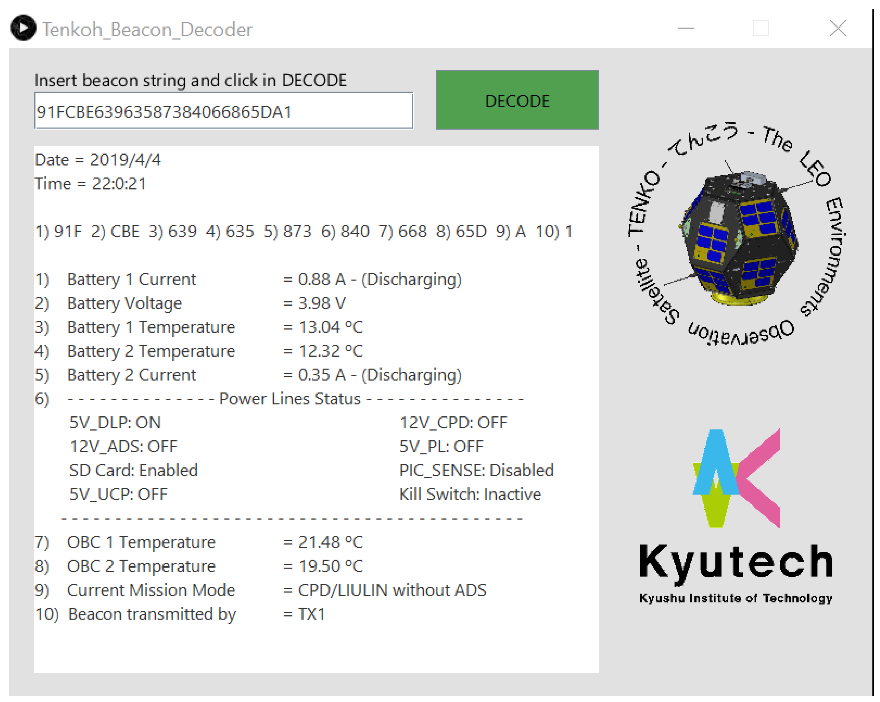
4.2.5. Spacecraft Status
5. Conclusions
Author Contributions
Funding
Acknowledgments
Conflicts of Interest
Abbreviations
| ADC | Analog to Digital Converter |
| ADS | Attitude Determination Subsystem |
| COMM | Telecommunications subsystem of Ten-Koh |
| CCU | Communications Control Unit (of Ten-Koh COMM) |
| CFRP | Carbon Fiber Reinforced Polymer |
| CFRTP | Carbon Fiber-Reinforced Thermoplastic |
| ECU | Experiment Control Unit |
| EPS | Electrical Power Subsystem |
| GFRP | Glass Fiber Reinforced Polymer |
| GNSS | Global Navigation Satellite System |
| GOSAT | Greenhouse gases Observing SATellite |
| GPIO | General-Purpose Input Output |
| CPD | Charged Particle Detector, one of Ten-Koh payloads |
| COTS | Commercial off-the-shelf |
| DLP | Double Langmuir Probe, one of Ten-Koh payloads |
| I2C | Inter-Integrated Circuit (protocol) |
| JAXA | Japan Aerospace Exploration Agency |
| Kyutech | Kyushu Institute of Technology |
| LEO | Low Earth Orbit |
| LEOP | Launch and Early phase (of the Ten-Koh mission) |
| MCU | Main Controller Unit (of Ten-Koh OBC) |
| MGS | Main Ground Station |
| OBC | Onboard computer |
| OCP | Over-Current Protection |
| PCB | Printed Circuit Board |
| PIC | Programmable Integrated Circuit |
| PL | Payload |
| RTC | Real Time Clock |
| SPI | Serial peripheral interface (protocol) |
| TTL | Transistor–transistor logic |
| UHF | Ultra-High Frequency |
| UCP | Ultracapacitor |
| UV | Ultraviolet |
References
- Sihver, L.; Kodaira, S.; Ambrožová, I.; Uchihori, Y.; Shurshakov, V. Radiation Environment Onboard Spacecraft at LEO and in Deep Space. In Proceedings of the 2016 IEEE Aerospace Conference, Big Sky, MT, USA, 5–12 March 2016; pp. 1–9. [Google Scholar] [CrossRef]
- Suparta, W.; Gusrizal. The Variability of Space Radiation Hazards towards LEO Spacecraft. In Journal of Physics: Conference Series 539 (October 2014): 012023; IOP Publishing: Bristol, UK, 2014. [Google Scholar] [CrossRef]
- Chen, L.; Thorne, R.M.; Li, W.; Bortnik, J.; Turner, D.; Angelopoulos, V. Modulation of Plasmaspheric Hiss Intensity by Thermal Plasma Density Structure. Geophys. Res. Lett. 2012, 14, 39. [Google Scholar] [CrossRef]
- Cucinotta, F.A.; Cacao, E.; Kim, M.H.Y.; Saganti, P.B. Cancer and Circulatory Disease Risks for a Human Mission to Mars: Private Mission Considerations. Acta Astronaut. 2018, 13. [Google Scholar] [CrossRef]
- Miyake, S.; Kataoka, R.; Sato, T. Cosmic Ray Modulation and Radiation Dose of Aircrews during the Solar Cycle 24/25. Space Weather 2017, 15, 589–605. [Google Scholar] [CrossRef]
- Kirby, K.; Bushman, S.; Butler, M.; Conde, R.; Fretz, K.; Herrmann, C.; Hill, A.; Maurer, R.; Nichols, R.; Ottman, G. Radiation Belt Storm Probe Spacecraft and Impact of Environment on Spacecraft Design. In Proceedings of the 2012 IEEE Aerospace Conference, Big Sky, MT, USA, 3–10 March 2012; pp. 1–20. [Google Scholar] [CrossRef]
- Stratton, J.M.; Harvey, R.J.; Heyler, G.A. Mission Overview for the Radiation Belt Storm Probes Mission. Space Sci. Rev. 2013, 179, 29–57. [Google Scholar] [CrossRef] [Green Version]
- Angelopoulos, V. The THEMIS Mission. Space Sci. Rev. 2008, 141, 5–34. [Google Scholar] [CrossRef]
- Sharma, A.S.; Curtis, S.A. Magnetospheric Multiscale Mission. In Nonequilibrium Phenomena in Plasmas; Astrophysics and Space Science Library; Burton, W.B., Kuijpers, J.M.E., Van Den Heuvel, E.P.J., Van Der Laan, H., Appenzeller, I., Bahcall, J.N., Bertola, F., Cassinelli, J.P., Cesarsky, C.J., Engvold, O., et al., Eds.; Springer: Dordrecht, The Netherlands, 2005; pp. 179–195. [Google Scholar] [CrossRef]
- Nakamura, Y.; Fukuda, S.; Shibano, Y.; Ogawa, H.; Sakai, S.I.; Shimizu, S.; Soken, E.; Miyazawa, Y.; Toyota, H.; Kukita, A.; et al. Exploration of Energization and Radiation in Geospace (ERG): Challenges, Development, and Operation of Satellite Systems. Earth Planets Space 2018, 70, 102. [Google Scholar] [CrossRef]
- Santandrea, S.; Gantois, K.; Strauch, K.; Teston, F.; Tilmans, E.; Baijot, C.; Gerrits, D.; Team, P.I.; De Groof, A.; Schwehm, G.; et al. PROBA2: Mission and Spacecraft Overview. Sol. Phys. 2013, 286, 5–19. [Google Scholar] [CrossRef]
- Nils, O.; Rune, F. Exploring Geospace from Space: The Swarm Satellite Constellation Mission. Space Res. Today 2018, 203, 61–71. [Google Scholar] [CrossRef]
- Xapsos, M.A.; O’Neill, P.M.; O’Brien, T.P. Near-Earth Space Radiation Models. IEEE Trans. Nucl. Sci. 2013, 60, 1691–1705. [Google Scholar] [CrossRef]
- Dudziak, R.P.; Tuttle, S.L.; Okuyama, K.; Lidtke, A.A.; Fajardo Tapia, I.; Gonzales, J.D. Practical Considerations of Integrating a Passive Thermal Control System onto Small-Satellites-the Ten-Koh Case Study. In Proceedings of the 49th International Conference on Environmental Systems, Boston, MA, USA, 7–11 July 2019. [Google Scholar]
- Bendoukha, S.A.; Okuyama, K.I.; Bianca, S.; Nishio, M. Control System Design of an Ultra-Small Deep Space Probe. Energy Proced. 2016, 100, 537–550. [Google Scholar] [CrossRef]
- Eickhoff, J. A Combined Data and Power Management Infrastructure: For Small Satellites; Springer Aerospace Technology; Springer-Verlag: Heidelberg, Germany, 2013; pp. 51–52. ISBN 978-3-642-35556-1. [Google Scholar]
- Reyes, R.; Faizullin, D.; Fajardo, I.; Hiraki, K.; Okuyama, K. Nano-satellite TEN-KOH Attitude Determination Subsystem: Architecture and Initial In-orbit Results. In Proceedings of the 32nd International Symposium on Space Technology and Science & 9th Nano-Satellite Symposium, Fukui, Japan, 15–21 June 2019. [Google Scholar]
- Gonzalez-Llorente, J.; Lidtke, A.A.; Hatanaka, K.; Kawauchi, R.; Okuyama, K.I. Solar Module Integrated Converters as Power Generator in Small Spacecrafts: Design and Verification Approach. Aerospace 2019, 6, 61. [Google Scholar] [CrossRef]
- Dachev, T.P.; Bankov, N.G.; Tomov, B.T.; Matviichuk, Y.N.; Dimitrov, P.G.; Häder, D.-P.; Horneck, G. Overview of the ISS Radiation Environment Observed during the ESA EXPOSE-R2 Mission in 2014–2016. Space Weather 2017, 15, 1475–1489. [Google Scholar] [CrossRef]
- Dorman, L.I.N.; Iucci, A.V.; Belov, A.E.; Levitin, E.A.; Eroshenko, N.G.; Ptitsyna, G.; Villoresi, G.V.; Chizhenkov, L.I.; Gromova, M.; Parisi, M.I.; et al. Space Weather and Space Anomalies. Ann. Geophys. 2005, 23, 3009–3018. [Google Scholar] [CrossRef]
- Takuji, E. A Miniature GNSS Smart Antenna for Space Applications. Available online: https://www3.chubu.ac.jp/documents/research/news/23446/23446_ff3c8b99cf080eb09b25a5609caf56a3.pdf (accessed on 26 August 2019).
- Gosat-2 Launch Information.Pdf. Available online: http://www.jaxa.jp/press/2018/08/files/20180828_h2af40_j.pdf (accessed on 31 March 2019).
- Bilitza, D. IRI the International Standard for the Ionosphere. Adv. Radio Sci. 2018, 16, 1–11. [Google Scholar] [CrossRef] [Green Version]
- International Reference Ionosphere-IRI. 2016. Available online: https://ccmc.gsfc.nasa.gov/modelweb/models/iri2016_vitmo.php (accessed on 31 March 2019).
- Scott, F.N. Future Trends in Satellite Systems and Their Impact on Material Choice. Mater. Today 1999, 2, 7–10. [Google Scholar] [CrossRef]
- Ken Chang, C.; Kamaratos, E. Theoretical Studies of Radiation Effects in Composite Materials for Space Use, NASA Contractor Report 3618. 1982. Available online: https://ntrs.nasa.gov/archive/nasa/casi.ntrs.nasa.gov/19820026459.pdf (accessed on 28 March 2019).
- Dachev, T.P.; Semkova, J.V.; Tomov, B.T.; Matviichuk, Y.N.; Dimitrov, P.G.; Koleva, R.T.; Bankov, N.G.; Shurshakov, V.A.; Benghin, V.V.; Yarmanova, E.N.; et al. Overview of the Liulin Type Instruments for Space Radiation Measurement and Their Scientific Results. Life Sci. Space Res. 2015, 4, 92–114. [Google Scholar] [CrossRef] [PubMed]
- Chen, F.F. Langmuir Probe Diagnostics, Mini-Course on Plasma Diagnostics. In Proceedings of the IEEE-ICOPS Meeting, Jeju, Korea, 5 June 2003; p. 42. [Google Scholar]
- McIlwain, C.E. Magnetic Coordinates. Space Sci. Rev. 1966, 5, 585–598. [Google Scholar] [CrossRef]
- Chulliat, A.; Macmillan, S.; Alken, P.; Beggan, C.; Nair, M.; Hamilton, B.; Woods, A.; Ridley, V.; Maus, S.; Thomson, A. The US/UK World Magnetic Model for 2015–2020: Technical Report; National Geophysical Data Center, NOAA: Silver Spring, MD, USA, 2015. [CrossRef]
- Dong, C.; Li, K.; Jiang, Y.; Arola, D.; Zhang, D. Evaluation of Thermal Expansion Coefficient of Carbon Fiber Reinforced Composites Using Electronic Speckle Interferometry. Opt. Express 2018, 26, 531. [Google Scholar] [CrossRef] [PubMed]
- Arase (ERG) Geospace Probe|Spacecraft. ISAS. Available online: http://www.isas.jaxa.jp/en/missions/spacecraft/current/erg.html (accessed on 21 April 2019).
- Harboe Sorensen, R.; Muller, R. Radiation Testing of UV EPROMs, Flash EPROMs and EEPROMs for Space Applications. ESA Report ESA-QCA0076TS. 1996. Available online: https://escies.org/download/webDocumentFile?id=1026 (accessed on 3 August 2019).
- Baker, D.N.; Erickson, P.J.; Fennell, J.F.; Foster, J.C.; Jaynes, A.N.; Verronen, P.T. Space Weather Effects in the Earth’s Radiation Belts. Space Sci. Rev. 2017, 214, 17. [Google Scholar] [CrossRef]


| Item | Instrument/Sensor | Measurement Range |
|---|---|---|
| Charged particle detector based on CMOS sensors | 6 detectors for protons, electrons and ions. 2 x-ray detectors | The final range will be defined based on ground calibration and orbital data. |
| Dosimeter for space radiation. | Liulin type dosimeter | Dose rate [Gy/h]: 1.12 × to 0.188 Flux [particles/cm/s]: 0.01–10,000 Deposited Energy [MeV]: 0.081–20.833 |
| Material mission | Strain measurements Temperature measurements | Strain: 10,000 × to 1 × Temperature [C]: −55–150 |
| DLP | Electron density/temperature | Current [A]: +/−10 × Minimum current [A]: 80 × Voltage [V]: +/− 11 |
| Magnetic field measurements | Magnetometer based on 3-axis magnetoresistive sensor | +/−2 × [T] |
| Phase Number | Mission Phase | Duration | Description |
|---|---|---|---|
| 1 | LEOP: Launch early operations | 2–3 weeks |
|
| 2 | Normal Operation | 1 year starting after 3 weeks from the launch |
|
| 3 | Extended Operation | 1 year, starting after Normal Operation |
|
| 4 | End of mission | 3 years |
|
| Challenge and Its Origin | Solution | |
|---|---|---|
| a | Challenge: Available generated power Origin: SmallSat constraint | Maximized solar array area + payload operations with reduced time duration. |
| b | Challenge: Available space location, mass and structure interface for some payload instruments Origin: SmallSat constraint | Platform subsystems were compactly accommodated at the bottom of the central internal structure and the inside walls of the external structure to maximize payload space. Structure effects on the measured data need to be corrected for during result interpretation. |
| c | Challenge: Amount of data generated by the mission instruments Origin: SmallSat constraint | On-board storage capacity of up to 2 GB for the main payload instruments, EPS and ADS subsystems each. |
| d | Challenge: Structure design heritage Origin: Schedule for delivery on time | Shinen-2’s legacy structure with location for Ten-Koh components, considering thermal control, fields of view of antennas and sensors. |
| e | Challenge: Attitude determination and control vs attitude determination Origin: Schedule for delivery on time and keeping the CPD and magnetometer readings with reduced influence | An attitude determination only approach was adopted to meet schedule and cost constraints. |
| f | Challenge: COTS design heritage from previous missions Origin: Reliability and budget constraints | Use of avionics components from Shinen-2 and other small satellite missions wherever possible. |
| g | Challenge: Magnetic measurement system with no deployable boom Origin: Schedule constraint | Magnetometer instrument location was designated in the top panel of the satellite to reduce complexity from boom deployable system while keeping the schedule and measurements quality. |
| h | Challenge: Launch date fixed by JAXA Origin: Schedule constraint | Adopted a modular design approach, with re-use of the same microcontroller and other circuitry in all the subsystems. This also maximized software reuse. |
| Mission Instrument | Amount of Data Generated Per Single Measurement Per Channel [Bytes/ch] | Maximum Time Duration of the Experiment [minutes] | Data Generated for the Maximum Time Duration for 2 Channels [Bytes] |
|---|---|---|---|
| DLP | 3000 bytes (hi-res) | 15 min | 900,000 bytes (hi-res) |
| 1500 bytes (med-res) | 672,000 bytes (med-res) | ||
| 600 bytes (low-res) | 180,000 bytes (low-res) | ||
| CPD | 2528 bytes | 15 min | 75,840 bytes |
| ADS sensors | 64 bytes | 15 min | 57,600 bytes |
| Material mission | 60 bytes | 5 min | 18,000 bytes |
| Channel | Measured Resistor Value [G] | Relative Error from 1 [G] Resistor Nominal Value in % | Relative Error from SMU Measured Resistance in % |
|---|---|---|---|
| 1 (CHA1) | 1.0010 × | 0.1 | 0.82 |
| 2 (CHB1) | 1.0180 × | 1.8 | 2.53 |
| 3 (CHA2) | 1.048 × | 4.8 | 5.5 |
| 4 (CHB2) | 9.944 × | 0.56 | 0.15 |
| SMU2400 | 9.929 × | 0.71 | —— |
| Spectrum | Epoch UTC | Geographic Location of the Satellite | L-Shell (McIlwain) | Dose Rate [Gy/h] | Dose Rate [rad/s] | Flux [particles/cm/s] |
|---|---|---|---|---|---|---|
| 1 | 08 November 2018 04:25:55 | Lat [deg]: 25.98 Lon [deg]: 132.67 Altitude [km]: 609.33 | 1.144 | 1.93 | 5.444 × | 0.33 |
| 1 | 12 November 2018 05:06:50 | Lat [deg]: 29.55 Lon [deg]: 123.09 Altitude [km]: 608.41 | 1.206 | 2.66 | 7.389 × | 0.39 |
| 2 | 12 November 2018 05:07:29 | Lat [deg]: 27.16 Lon [deg]: 122.50 Altitude [km]: 607.76 | 1.161 | 0.39 | 0.2 | |
| 1 | 18 November 2018 04:33:53 | Lat [deg]: 26.04 Lon [deg]: 130.75 Altitude [km]: 604.32 | 1.143 | 2.79 | 7.750 × | 0.26 |
| 2 | 18 November 2018 04:34:08 | Lat [deg]: 25.11 Lon [deg]: 130.53 Altitude [km]: 604.05 | 1.129 | 0.92 | 2.556 × | 0.23 |
© 2019 by the authors. Licensee MDPI, Basel, Switzerland. This article is an open access article distributed under the terms and conditions of the Creative Commons Attribution (CC BY) license (http://creativecommons.org/licenses/by/4.0/).
Share and Cite
Fajardo, I.; Lidtke, A.A.; Bendoukha, S.A.; Gonzalez-Llorente, J.; Rodríguez, R.; Morales, R.; Faizullin, D.; Matsuoka, M.; Urakami, N.; Kawauchi, R.; et al. Design, Implementation, and Operation of a Small Satellite Mission to Explore the Space Weather Effects in LEO. Aerospace 2019, 6, 108. https://doi.org/10.3390/aerospace6100108
Fajardo I, Lidtke AA, Bendoukha SA, Gonzalez-Llorente J, Rodríguez R, Morales R, Faizullin D, Matsuoka M, Urakami N, Kawauchi R, et al. Design, Implementation, and Operation of a Small Satellite Mission to Explore the Space Weather Effects in LEO. Aerospace. 2019; 6(10):108. https://doi.org/10.3390/aerospace6100108
Chicago/Turabian StyleFajardo, Isai, Aleksander A. Lidtke, Sidi Ahmed Bendoukha, Jesus Gonzalez-Llorente, Rafael Rodríguez, Rigoberto Morales, Dmytro Faizullin, Misuzu Matsuoka, Naoya Urakami, Ryo Kawauchi, and et al. 2019. "Design, Implementation, and Operation of a Small Satellite Mission to Explore the Space Weather Effects in LEO" Aerospace 6, no. 10: 108. https://doi.org/10.3390/aerospace6100108