
Development and Evaluation of an Enhanced Virtual Reality Flight Simulation Tool for Airships


Department of Aerospace Engineering, Toronto Metropolitan University, Toronto, ON M5B 2K3, Canada
*
Author to whom correspondence should be addressed.
Aerospace 2023, 10(5), 457; https://doi.org/10.3390/aerospace10050457
Submission received: 19 January 2023
/
Revised: 9 May 2023
/
Accepted: 11 May 2023
/
Published: 15 May 2023
(This article belongs to the Special Issue Mission Analysis and Design of Lighter-than-Air Flying Vehicles)
Abstract
:A real-time flight simulation tool is proposed using a virtual reality head-mounted display (VR-HMD) for remotely piloted airships operating in beyond-line-of-sight (BLOS) conditions. In particular, the VR-HMD was developed for stratospheric airships flying at low/high altitudes. The proposed flight simulation tool uses the corresponding aerodynamics characteristics of the airship, the buoyancy effect, mass balance, added mass, propulsion contributions and ground reactions in the FlightGear Flight Simulator (FGFS). The VR headset was connected to the FGFS along with the radio controller containing the real-time orientation/state of each button, which is also simulated to provide better situational awareness, and a head-up display (HUD) that was developed to provide the required flight data. In this work, a system was developed to connect the FGFS and the VR-capable graphics engine Unity to a PC and a wireless VR-HMD in real time with minimal lag between data transmission. A balance was found for FGFS to write to a CSV file at a period of 0.01 s. For Unity, the file was read every frame, which translates to around 0.0167 s (60 Hz). A test procedure was also conducted with a similar rating technique based on the NASA TLX questionnaire, which identifies the pilot’s available mental capacity when completing an assigned task to assure the comfortability of the proposed VR-HMD. Accordingly, a comparison was made for the aircraft control using the desktop simulator and the VR-HMD tool. The results showed that the current iteration of the system is ideal to train pilots on using similar systems in a safe and immersive environment. Furthermore, such an advanced portable system may even increase the situational awareness of pilots and allow them to complete a sizeable portion of actual flight tests with the same data transmission procedures in simulation. The VR-HMD flight simulator was also conceived to express the ground control station (GCS) concept and transmit flight information as well as the point of view (POV) visuals in real-time using the real environment broadcast using an onboard camera.
Keywords:
virtual reality; flight simulation; ground control station; airship; flight test; training1. Introduction
Maintaining stability and operating autonomously are the main challenges related to the prolonged deployment of airships, and in-depth studies of flight operations are an important step toward deploying stratospheric hybrid airships [1]. A substantial amount of work has been carried out to enhance the design and development of airships, including several research projects and some stratospheric airship technology demonstrations such as HiSentinel by the Southwest Research Institute (SwRI) and Aerostar International Inc. (Sioux Falls, SD, USA) [2], the Sceye Stratospheric Airship by Sceye Inc. (Moriarty, NM, USA) [3], the Integrated Sensor is Structure (ISIS) by DARPA [4], the High-Altitude Long-Endurance Demonstrator (HALE-D) by Lockheed Martin (Bethesda, MD, USA) [5] and Thales Alenia Space Airship by the Thales group (New Castle, DE, USA) [6].
With the help of modelling and simulation, the development cost of an aerial vehicle may be lowered [7,8]. Moreover, the development of a flight simulation structure for a remotely piloted air vehicle using the same techniques and subsystems enables the validation and verification of concepts and systems, optimization of the design and, additionally, the enhancement of flying techniques and performance [9]. Nowadays, several types of flight simulators are available for different purposes, ranging from desktop platforms to more sophisticated training simulators and advanced X-DOF cockpit simulators [10]. Traditional simulators integrate flight dynamics models and simulation subsystems with a hardware cockpit mock-up, an outside visual and motion simulation [11]. Sometimes, these complex tools may exceed the cost of the actual product due to highly demanding quality standards for both hardware and software. Therefore, it is important to find the optimum cost/benefit ratio to reach an acceptable level of realism while considering the final cost [12].
VR provides a promising substitute to traditional simulators [13]. VR technology provides the opportunity to replace the entire reality with virtual objects with no limitations to what this could be. The difference between VR technology and conventional screens is the three-dimensional capability of VR compared to the two-dimensional representation of traditional screens. While most research and commercial applications use VR to put the pilot in a virtual cockpit, some use it to emulate an HUD with the out-the-window (OTW) laid behind the HUD visuals [14,15]. In any case, the following three “pillars” play major roles to ensure the usability of the technology among all targeted users: immersion, presence and interactivity. Immersion is defined as a psychological experience often governed by various technological limitations including the field of view (FOV), resolution, latency and trackability. Presence refers to the state or experience of a user in the virtual environment that may or not be related to the physical environment. Interactivity is the degree to which the user can control the virtual environment using a medium. According to some studies, these three pillars together constitute user satisfaction and comfort while using VR headsets [16,17].
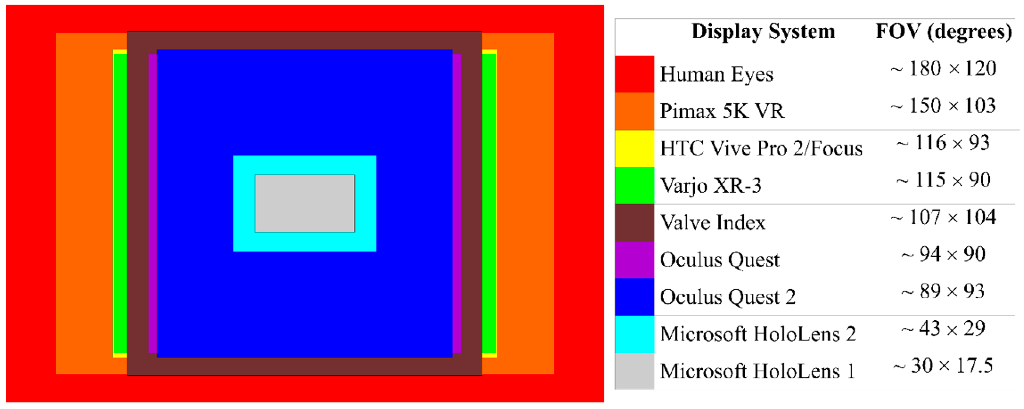
However, there are several concerns that are specifically involved when dealing with VR technology to ensure the comfort of users. Motion sickness or spatial disorientation are usually the first things that are discussed when talking about VR. This is because of the disconnect the user experiences between what they see and what they feel [18]. One way to lessen the chance of motion sickness is to provide a portable infrastructure with a masked simulated environment. The enhanced portable VR-HMD for flight simulation and evaluation is a great training tool for pilots [19,20]. VR-based flight simulators are small and more portable than a full-size cockpit mock-up simulator and are much less expensive. This also makes them the best choice for most operators who are looking to train pilots in remote locations and perform flight operations in remote locations. Utilizing the same digital telemetry radio system in real and simulated flights can provide more consistency between each phase of the design [21]. Another key aspect to consider when working with VR headsets is human perception and behavior when using the application. One of such factors is the FOV [22]. Figure 1 compares the FOV of human eyes with various VR and mixed reality (MR) headsets. As illustrated, human eyes have an average total FOV of about 180 × 120, while the Oculus Quest only has an FOV of around 94 × 90. In this work, an Oculus Quest 2 (Meta, Cambridge, MA, USA) has been used to study the simulated flight environment.
Augmented reality (AR) is a display device that enhances the real-world environment using virtual content and shows this on a screen. The usage of AR and VR technologies for futuristic vehicles or cockpit design is prevailing widely. In 2014, Aero Glass developed an application that could populate a large volume of ADS-B and other avionic information in the Osterhout Design Group (ODG) R-7 smart glasses [23,24]. It generated the information with respect to the pilot’s head position and orientation in a 3D environment. In 2016, Epson Moverio BT-300 smart glasses were used as a head-mounted display (HMD) to fly DJI Phantom quadcopters [25]. In 2016, Japan Airlines (JAL) demonstrated the idea of using AR to train pilots with a realistic flight simulator [24,25]. In 2017, Bell Helicopters began exploring the idea of an augmented reality futuristic cockpit system for their FCX-001 concept helicopter [25]. In 2021, Bombardier Aviation developed a full-size AR-based cockpit display system (CDS) for next-generation flight deck HMI design practices [25].

The VR-HMD simulator allows the operator to speed up plans to use VR headsets for real flights and to provide an integrated product that aims to train pilots from flight simulation to real flights using the same data transmission techniques. Utilizing the same digital telemetry radio system in real and simulated flights can provide more consistency between each phase of the design. Furthermore, the new flight simulator equipped with VR can be provided to customers for training and operational flying purposes with the same data transmission techniques in a simulated environment. Moreover, VR setups are small and portable, which makes them the best choice for most operational cases where customers are interested in operating in remote locations, particularly for airship-related missions. Using this new technology, the required time to train pilots will significantly drop compared to the existing technologies as the integrated VR-HMD system will be used from start to finish to train the pilots for actual flight. Consequently, the VR-HMD flight simulator will allow the operator to accomplish the goal of transiting from simulated training to actual flight with a single united system. The proposed portable integrated VR-HMD flight simulator has the potential to open up a new generation of technology that costs just a few thousand dollars compared to existing separate GCS and full-size cockpit mock-up simulators, which are significantly costlier. Such an advanced system is important to complete missions in real time from remote locations, lower pilot workload and increase situational awareness.
2. Methodology
In Section 2, the methodology used for the development of the VR-HMD flight simulator is presented. Accordingly, in Section 2.1, the airship architecture is presented with the details of the geometry parameters. Next, in Section 2.2, the flight simulator architecture including the flight dynamics model and the sub-sections of the flight simulator are presented in detail. In Section 2.3, the VR simulation application developed for the purpose of this study is introduced. Finally, in Section 2.4, the test procedure for the evaluation of the proposed tool is presented along with the research ethics board (REB) questionnaire.
2.1. Airship Architecture
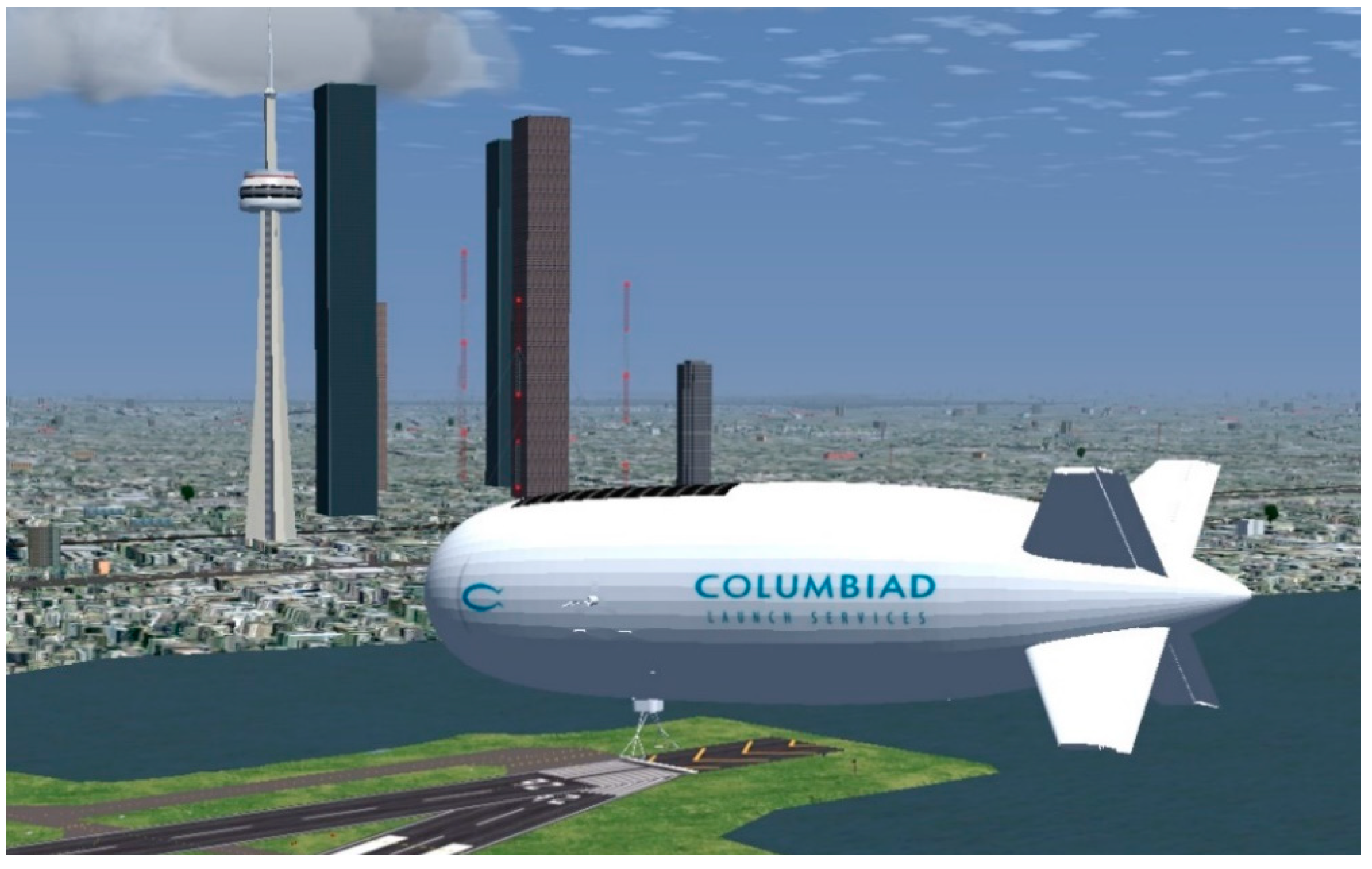
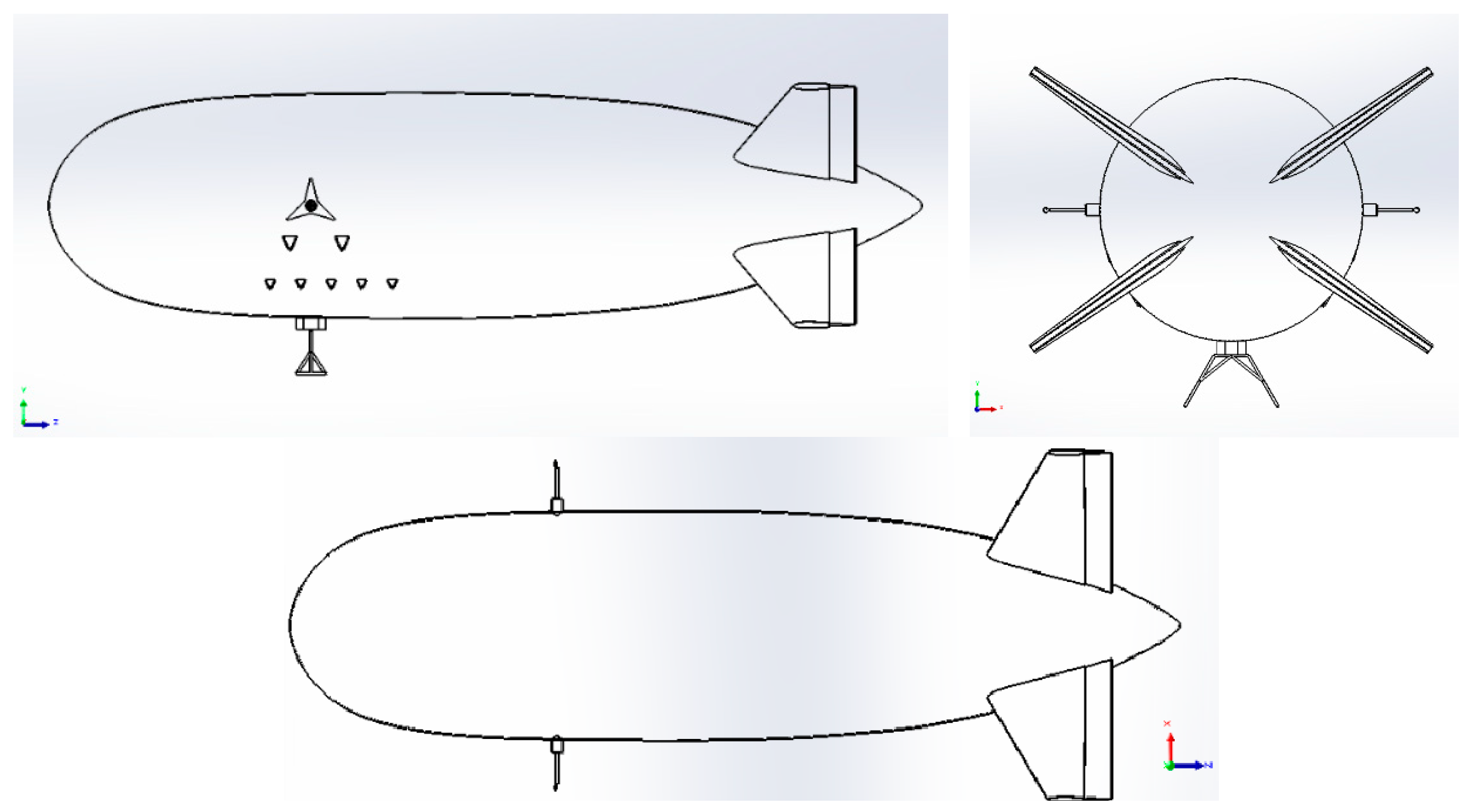
Herein, two models for stratospheric airship design are introduced. The first one is high-altitude architecture, with the mission to carry the desired payload to 70,000 ft and station-keep for a long time (e.g., several months and even years). The precise sizing characteristics are not the purpose of this work. The stratospheric airship uses two electrical engines, both placed at ~30% of the airship length from the nose, as presented in Figure 2 and Figure 3. The engine location allows the airship to use thrust vectoring to generate sufficient pitch and yaw moments. The hybrid architecture is designed to employ the communication system, solar panels, fuel cells and batteries and station-keep for a long time. The hull uses a circular cross-section multi-ellipsoid geometry, and the tail has a cross-shaped four-fin empennage configuration (X layout) with inflated fixed fins and ruddervator configuration to provide stability in both longitudinal and lateral directions.
The second model is a scaled-down version of the base architecture to carry the desired payload to 10,000 ft and corresponds to the low-altitude demonstrator to validate the control and navigation systems. The low-altitude demonstrator model is considered to validate the simulator model in low-altitude scenarios using actual flight test results and then scale up to the stratospheric model. The geometry of the second airship is presented in Figure 2, with different parameters in Table 1.
2.2. Flight Simulator Architecture
The desktop flight simulator was developed for the hybrid airship where beyond-line-of-sight operations are of interest. The proposed flight simulator was developed as a modular platform using the FGFS such that it is scalable and low-cost. FGFS offers a free and open-source multi-platform capability with atmospheric and orbital flight characteristics. It has been widely used in aerospace research and industry. The flight simulation uses a simulated atmosphere, power, equations of motion, aerodynamics, buoyant forces, gravity, mass, added mass and inertia, as shown in Figure 4, to study the behavior of the airship in different flight conditions [28]. Hence, different types and scales of the airship model can be simply simulated to study the behavior of the base design at various altitudes and flight conditions. To set up the flight simulator architecture, the geometry of the airship described in Table 1 was modelled in FGFS using the Flight Dynamics Model (FDM) provided by JSBSim [29]. Accordingly, the corresponding aerodynamics of the hybrid airship, along with the buoyant forces, added mass, mass balance, ground reactions, atmosphere and propulsion contributions, were considered in the development of the flight simulator. These details are all gathered in separate extensible markup language (XML) configuration files to enable a modular platform for the flight simulator architecture.
The matrix form of the equations of motion for an aircraft can be shown using the following equations for the longitudinal and lateral direction motions, respectively [30] (see nomenclature list):
For airships, in addition to the aerodynamic terms, significant force and moment terms due to the static buoyancy and inertial terms due to the displaced mass of air may be seen. Accordingly, the equations of motion for airships may be written as follows [31] (see nomenclature list):
Considering the equations of motion presented in Equation (3), the decoupled longitudinal equations of motions of the airship could be presented as follows [31] (see nomenclature list):
To define the equations of motion, two different functions are usually used. The first one is based on the Euler angle estimations providing roll, pitch and yaw angles. A direction–cosine matrix (DCM) function is usually defined to estimate the Earth-to-body relationship using the roll, pitch and yaw angles in radians. The second function is responsible for estimating the equations of motion in accordance with the quaternion definition. Likewise, a DCM function is defined to consider the Earth-to-body axis rotation working with the four components of the quaternion. The definition of the state vectors is explained in Table 2 as follows:
The control surfaces are bound with the FrSky Taranis X9 radio transmitter (FrSky Electronic Co., Jiangsu, China) through a wireless USB dongle to transfer the pilot’s commands and control the airship during flight. Additionally, an HUD was designed for the desktop simulator to provide aircraft performance data and environment information on the screen, as shown in Figure 5, to increase pilots’ situational awareness. Finally, as the airship flight simulator is designed to enhance the flight test and training procedures, the autopilot features consist of basic modes such as pitch hold and altitude hold developed with the help of PID controllers. Features for data logging and real-time plotting are also available with a “.CSV” output file working in real time, and these can be connected to the real-time plotting tools. The CSV file is used by the VR-HMD to update the HUD elements in real time.
2.3. VR Simulation
To accurately simulate the final goal of deploying a VR-based solution to monitor and pilot an airship in BVLOS scenarios, a VR application was developed using Unity software (Unity Technologies, San Francisco, CA, USA). Unity was chosen as the main VR engine due to its ease of use and multi-platform compatibility capabilities. Within the VR application, the user/pilot is able to view a POV screen showing the simulated view from a POV camera located on the airship. Overlaid on top of the POV screen and locked to the pilot’s view will be the HUD, which will display all the necessary flight information the pilot will need to safely operate the airship. To give the pilot better awareness of the controls, a digital twin of the radio flight controller is also included within the VR environment. Not only is the position of the virtual radio flight controller tracked, but the orientation of the individual buttons, switches and control sticks is also tracked and displayed, thus reducing the disconnect the pilot might experience between their physical environment and the virtual environment while wearing the VR-HMD.
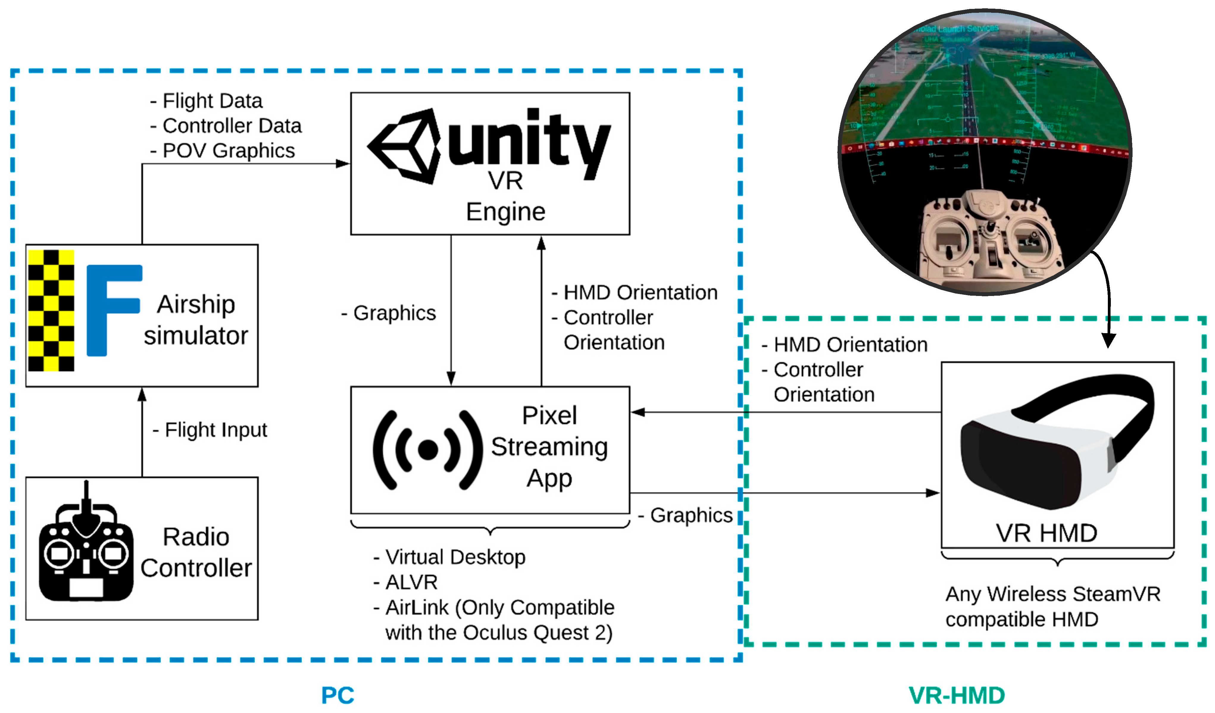
Figure 6 shows a simplified process flow of how the flight simulator graphics and data are handled and displayed on the wireless VR-HMD. The airship simulator receives flight input to control the simulated airship, and at the same time, an extra script records the flight data and controller data and exports them in a single CSV file in real time. The VR application reads the CSV file and updates the HUD elements as well as the controller elements. The desktop with the POV of the simulator is also captured and displayed in the VR environment. Using the flight data, controller data and desktop capture, the VR environment is rendered within the application. VR pixel streaming applications such as Virtual Desktop, ALVR and Air Link are used to wirelessly stream the rendered view of the VR application onto the VR-HMD. Each frame on the VR application is rendered based on the orientation of the VR-HMD in its physical space, providing more immersion to the pilot within the VR environment.
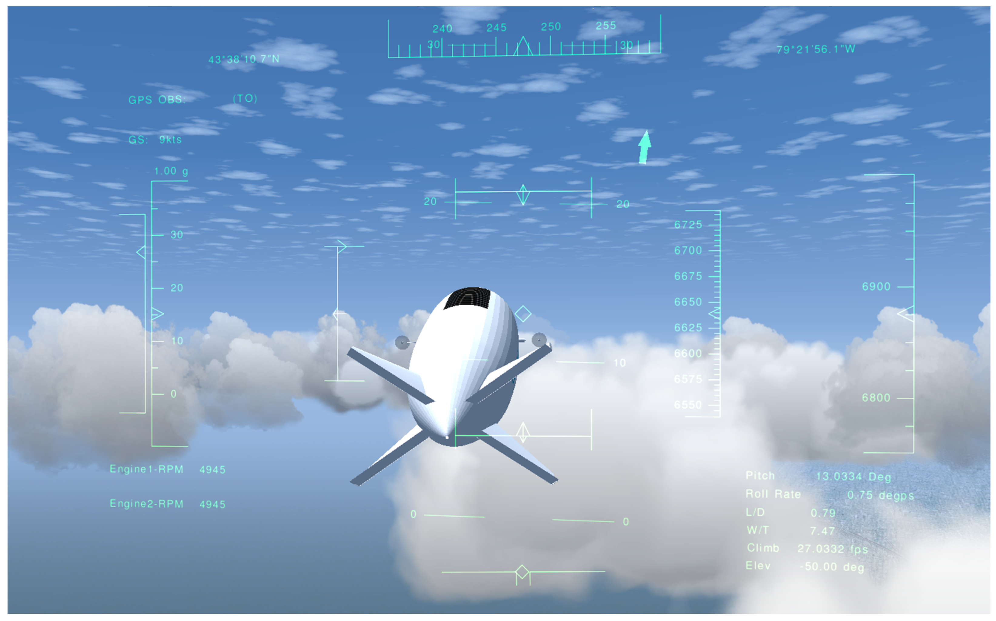
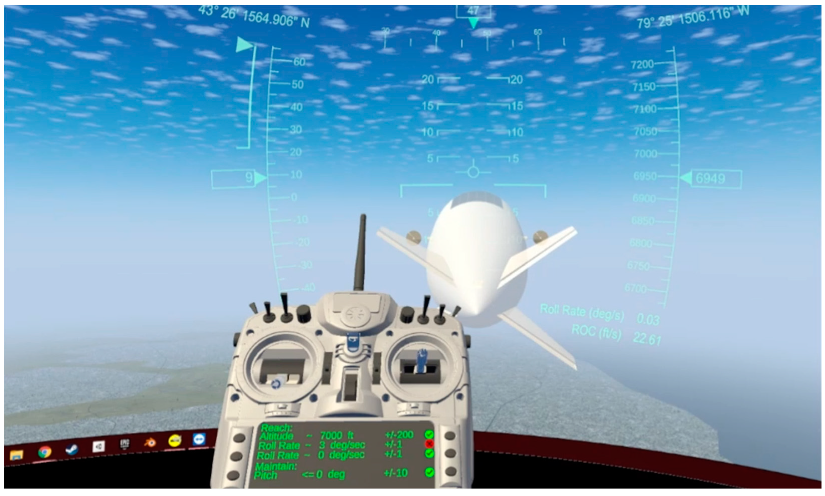
The resulting flight simulation described in Figure 6 is presented in Figure 7 with a view from the proposed VR-HMD. Using a live data export script written in Nasal within FlightGear (FlightGear developers & contributors, Burnsville, MI, USA), the live flight data, as well as the radio controller input values, were saved in a CSV file. A custom ReadCSV script within Unity was created to locate and open the data file exported by FlightGear. The ReadCSV script queries the last line within the CSV file on every frame and stores the values in an array variable simply named ‘DataArray’. The order in which the values being read from FlightGear are placed within DataArray is determined by the order used to save the data.
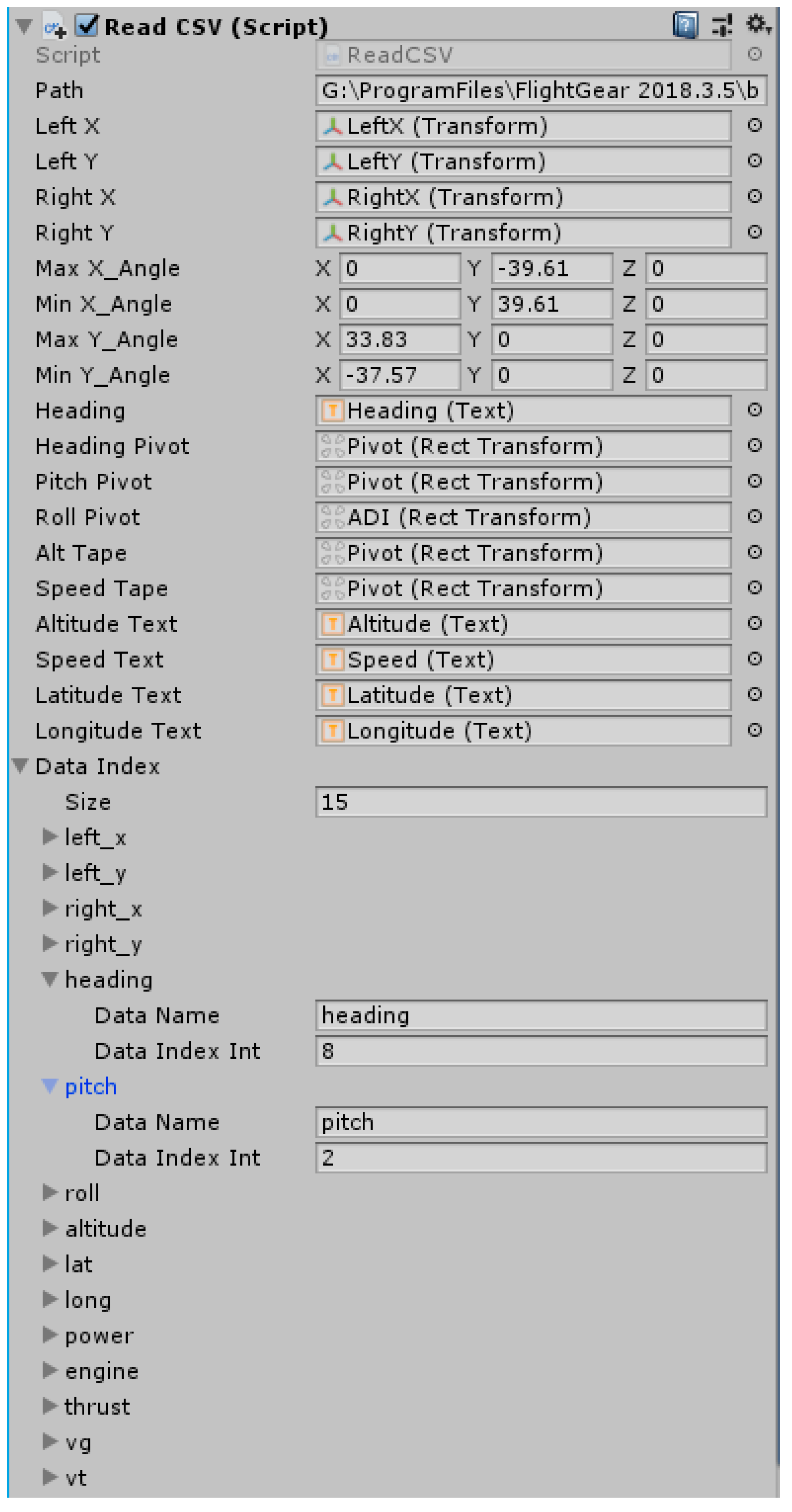
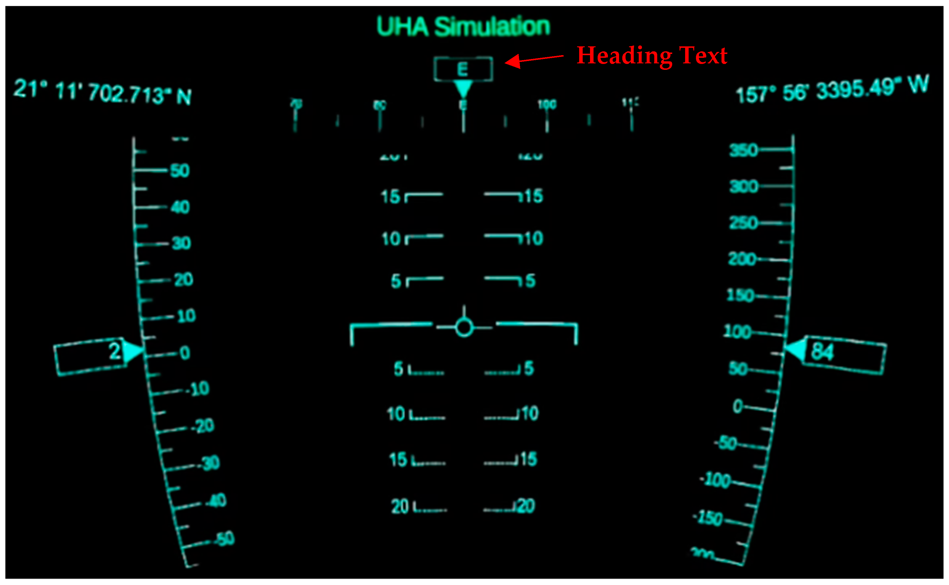
Many of the variables within the ReadCSV script were made public to create the GUI seen in Figure 8. This GUI is used to set up information such as the file ‘Path’ to the data CSV file. Another important setup through the GUI in Figure 8 is pairing the data received from FlightGear to the different elements within Unity. For example, the ‘Heading Text’ variable seen in Figure 8 refers to a text renderer object in Figure 9 that displays the heading information in the HUD, which is locked to the users’ view. The ‘Heading Text’ value changes based on the values within the DataArray variable. To let the application know which index within DataArray refers the heading of the aircraft, the ‘DataName’ and ‘DataIndexInt’ variables are set. In this example, the DataName is set to ‘heading’, and the DataIndexInt is set to 8, which is the index within the DataArray variable that corresponds to the heading of the aircraft. A similar setup can be seen for pitch, which pairs pitch to the index value of 2.
Using this single GUI, all the data received from FlightGear are paired to the objects within the virtual environment. This pairing is what allows the animations on the controller and the values on the HUD to be updated.
The screen displaying the POV of the aircraft is created using a desktop duplication plugin for Unity called uDesktopDuplication. The plugin provides the ability to use the built-in capability of the Windows OS to capture the desktop and display it within the Unity environment. Using the plugin to display the desktop screen on a curved surface within the virtual environment provides more immersion to the user.
As described in Figure 5, a secondary third-party pixel streaming application is used to transmit the visuals from the PC to the wireless VR-HMD. In the case of the test shown in Figure 6, ALVR was the streaming application. Although any VR pixel streaming application can be used depending on personal preference, ALVR was used for this paper as it was free to use. VR pixel streamers such as ALVR stream visual data from the PC to the wireless VR-HMD, while streaming head and controller orientation as well as any inputs from the HMD to the PC. A common downside of using streaming applications such as ALVR and Virtual Desktop is that they have an inherent lag in streaming over Wi-Fi. The lag in streaming can be made worse with a poor internet connection and/or a resource-hungry application.
2.4. VR Flight Simulator Test and Analysis
After the successful completion of the proposed symbology design, the VR-HMD flight simulator presented in Figure 6 was utilized for human flight tests. To understand the effect of the primary flight display (PFD) symbology on pilots, a complete flight envelope from takeoff to the desired station altitude was simulated. For all test cases, Billy Bishop Toronto City Airport (CYTZ), situated in the city of Toronto, was used as the local terrain, and a suitable flight path was developed to test users on specific operations that affect the airship safety (CFIT, loss of control and collision with object).
The test procedure was defined as follows:
- (1)
- Start the flight and take-off at CYTZ airport (Runway 08) on reaching ~10 knots and maintain a constant pitch of within 5 degrees.
- (2)
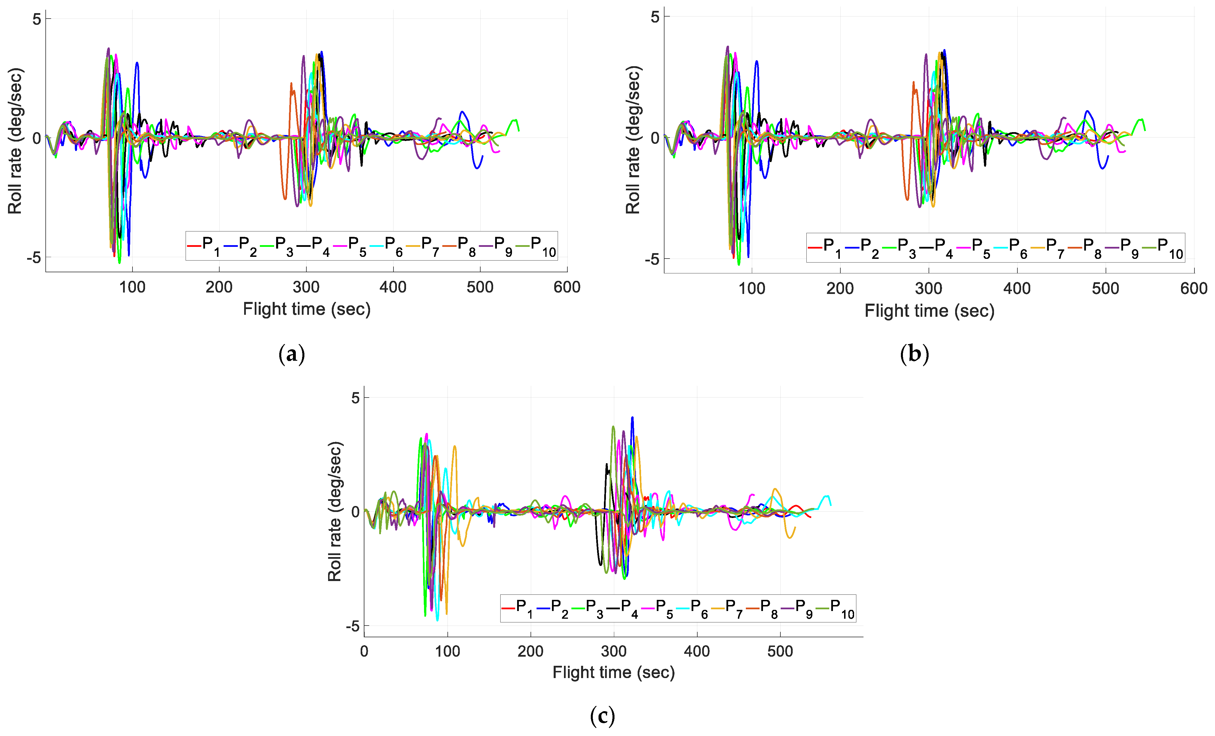
- Reaching an altitude of 2000 ft, turn to the right and try to reach a roll rate of 3 deg/s and then turn left and try to reach a zero roll rate by maintaining a constant pitch of always less than 5 deg.
- (3)
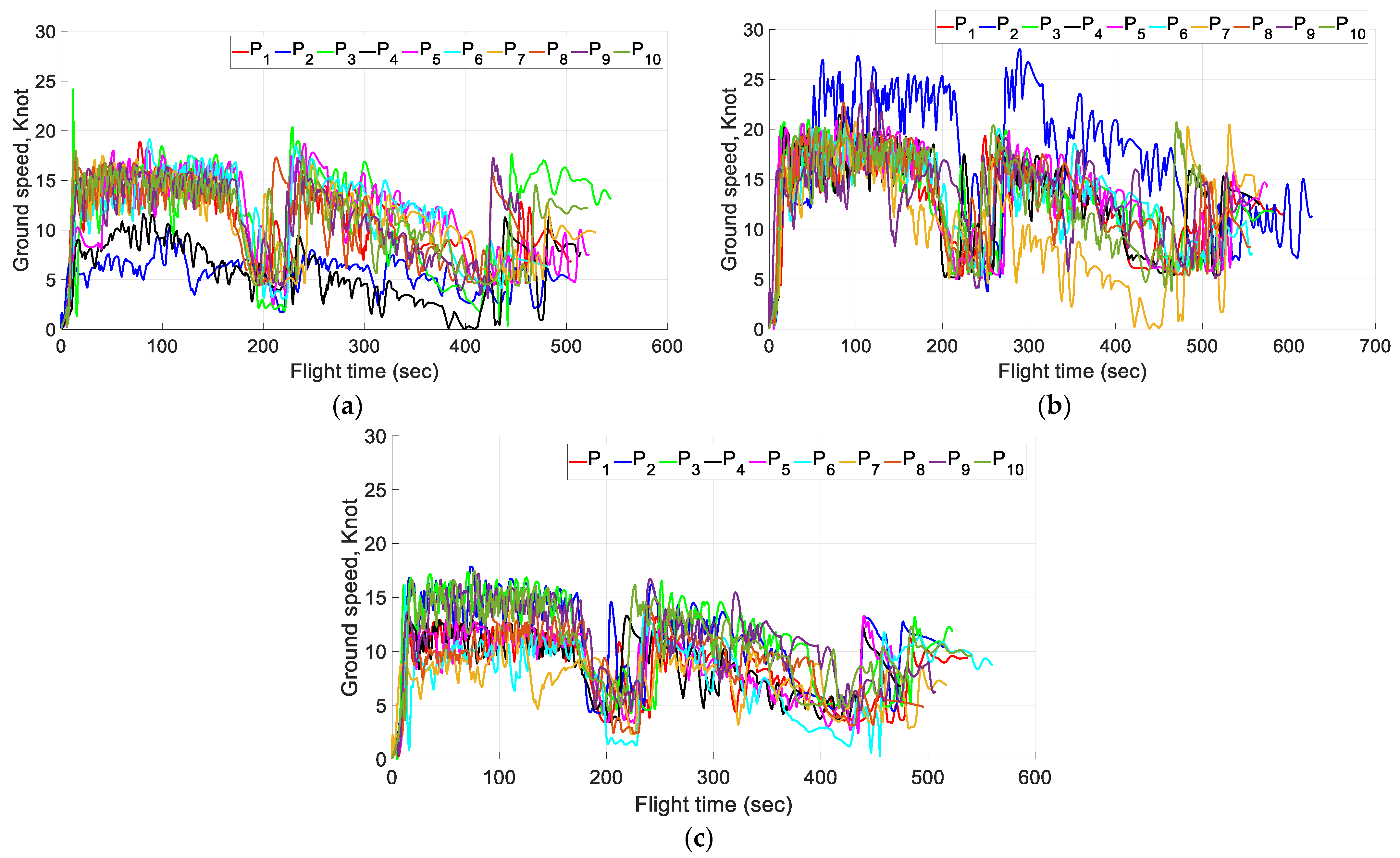
- Adjust the ballonet and helium volume and station for 10 s at a cruise altitude of ~5000 feet with airspeed below 15 knots.
- (4)
- On crossing the cruise altitude of 7000 ft, turn to the left and try to reach a roll rate of 3 deg/s and then turn right and try to reach a zero roll rate by maintaining a constant pitch of always less than 5 deg.
- (5)
- After crossing the altitude of 9000 ft, adjust the ballonet and helium volume and reach a climb rate of less than 20 ft per s to prepare for station-keeping at an altitude of 10,000 ft by aligning the airship.
- (6)
- Reduce the speed and maintain the 10,000 ft altitude.
- (7)
- Align the flight path angle with the other airships in the network and station-keep.
This flight plan tests the user’s ability to avoid all unsafe conditions while maintaining proper flight parameters. Towards the end of the test, the user must follow the proper flight path angle and other parameters to keep the airship at the desired station-keeping altitude at the proper waypoint.
Table 3 presents different variables considered while recording each user’s flight and the reason for choosing them. Each one of these parameters helps to study the impact of the proposed VR-HMD tools compared to the existing desktop flight simulators.
REB Questionnaire
- (a)
- Mental Demand (Low/High): How much mental activity was required for thinking, deciding, calculating, and remembering or searching for certain information that is being presented?
- (b)
- Physical Demand (Low/High): How much physical activity was required for pushing, pulling, turning, controlling or activating the controllers?
- (c)
- Temporal Demand (Low/High): How much pressure does the operator feel due to the rate or pace at which the tasks or task elements occurred?
- (d)
- Performance (Good/poor): How successful was the operator in accomplishing the goals of a given task set by the experimenter?
- (e)
- Effort (Low/High): How hard did the operator have to work both mentally and physically to accomplish the level of performance?
- (f)
- Frustration level (Low/High): How insecure, discouraged, irritated, stressed and annoyed versus secure, gratified, content, relaxed and complacent did the operator feel with the information presented?
The users were supposed to rate each individual component on a scale of 1 to 10, with 1 being the lowest and 10 being the highest.
3. Results and Discussion
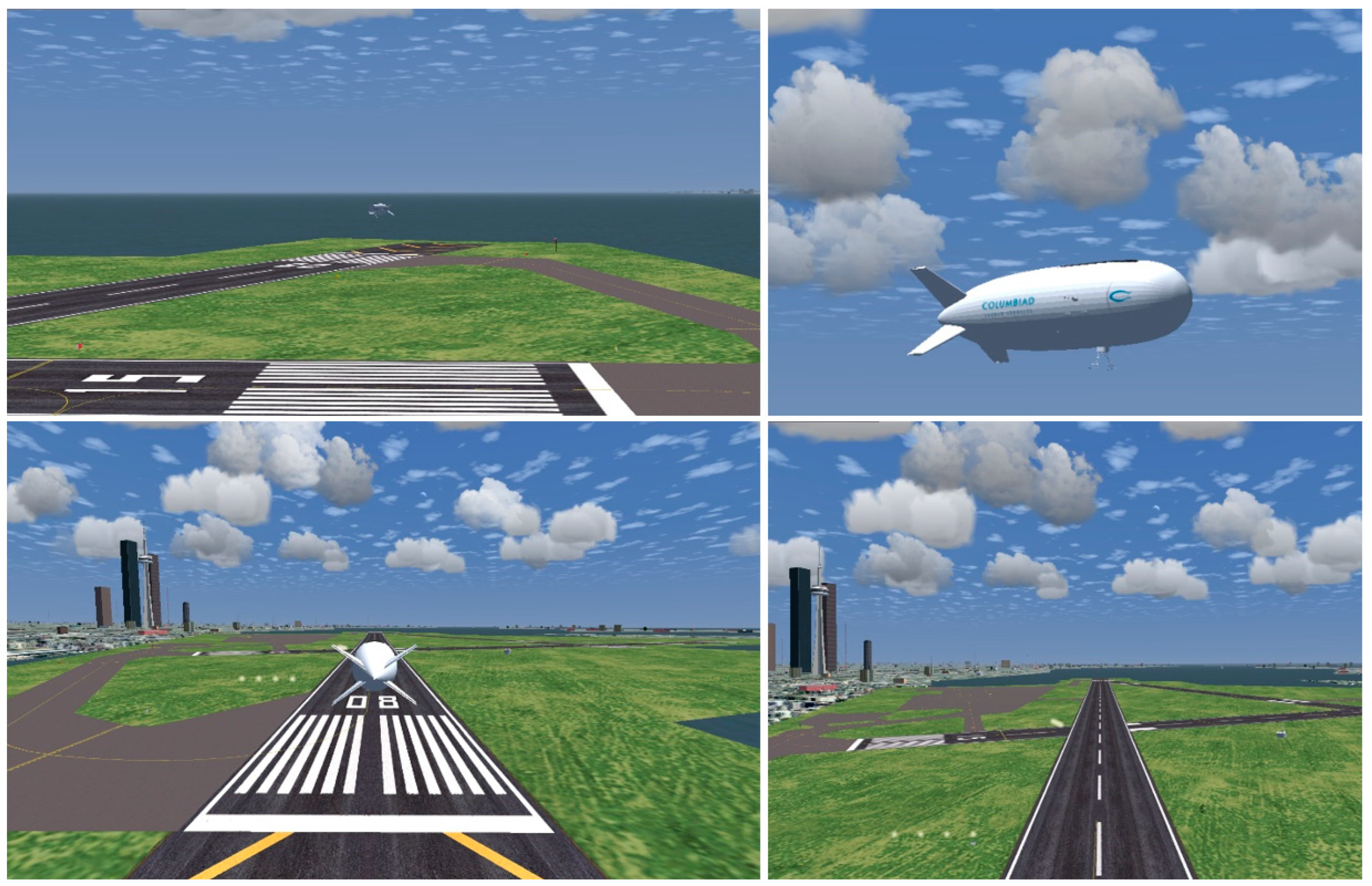
The resulting flight simulation view of the proposed simulator described in Figure 4 is presented in Figure 10 for different POVs. As the VR-HMD flight simulator was developed in the environment of the FGFS, the user could choose, organize or modify the graphical modes using the available setup menus and camera views, such as from the control tower, from the cockpit and from different positions on the airship, as shown in Figure 10.
The technical goal of this study was to develop a system that could connect two different software packages and two different pieces of hardware in real time with minimal lag between data transmission, the two different software packages being a flight simulator with a VR-capable graphics engine. In this case, the flight simulator that was chosen was FlightGear and the VR-capable graphics engine was Unity. The two pieces of hardware that were connected were a PC and a wireless VR-HMD, in this case, the Oculus Quest. The connection point between FlightGear and Unity was a single CSV file that both applications used to share information. FlightGear was the source for stored data and Unity was used to read the stored data. The connection point for the PC and Oculus Quest was the pixel streaming application ALVR. ALVR transmitted graphical data to the Oculus Quest and transmitted positional and input data to Unity on the PC.
The connection points between the software and hardware are where the biggest issue in lag needs to be addressed. In the case of the CSV file, lag occurs during the writing and reading process. To successfully read or write to a file, it must first be opened, then written to or read from, and finally closed and repeated individually by each application. The speed at which the reading and writing processes occur depends on the language being used. Another limiting factor is the frequency at which FlightGear logs data in the CSV file. If the frequency is too high, it can place a significant load on the PC, which will affect the performance of any application running at the time. If the frequency is too low, then the data received by the user will be too outdated to use and the transmission cannot be considered real-time. A balance was found for FlightGear to write to a CSV at a period of 0.01 s. For Unity, the file was read every frame, which translates to around 0.0167 s (60 Hz). Since the speed of the aircraft is not very high, 0.01 s was considered an acceptable margin to work within at this stage.
For the connection point between the PC and Oculus Quest, the bottleneck occurs at the pixel streaming application and Wi-Fi connection. On average, the acceptable latency of data transmission between the PC and VR for any pixel streaming application is between 22 and 32 ms in ideal conditions. Ideal conditions are where a strong Wi-Fi connection for the VR-HMD, a LAN connection for the PC and a 5 GHz connection are available. Internet speeds do not affect the latency. In situations of high latency, the resolution of the graphics is affected, until no transmission occurs. Another effect of high latency is that the user will receive outdated visual information. This means the user will see information that has already occurred in the flight simulator and it will be too late to react to any situation. Another issue will be input lag. Input lag stands for the time it takes between when the user inputs a command and when the resulting action occurs. This would cause less than ideal flying conditions for the user.
A final global aspect affecting lag and latency is the hardware specifications of the PC and VR-HMD. The tests referred to in this paper were conducted on a desktop PC and a laptop. The desktop PC ran on an AMD Ryzen 9, 3900X CPU, dual Nvidia GeForce RTX 2080 GPU, 64 GB RAM and 1 Tb SSD. The laptop ran on a Core i7 (7th Gen) CPU, Nvidia GeForce GTX 1050 GPU, 32 GB RAM, and 1 TB HDD. Both devices were able to run FlightGear, Unity and ALVR/Virtual Desktop with no latency issues. Performance on differently configured PCs will give a better understanding of which configurations would be best for the proposed system.
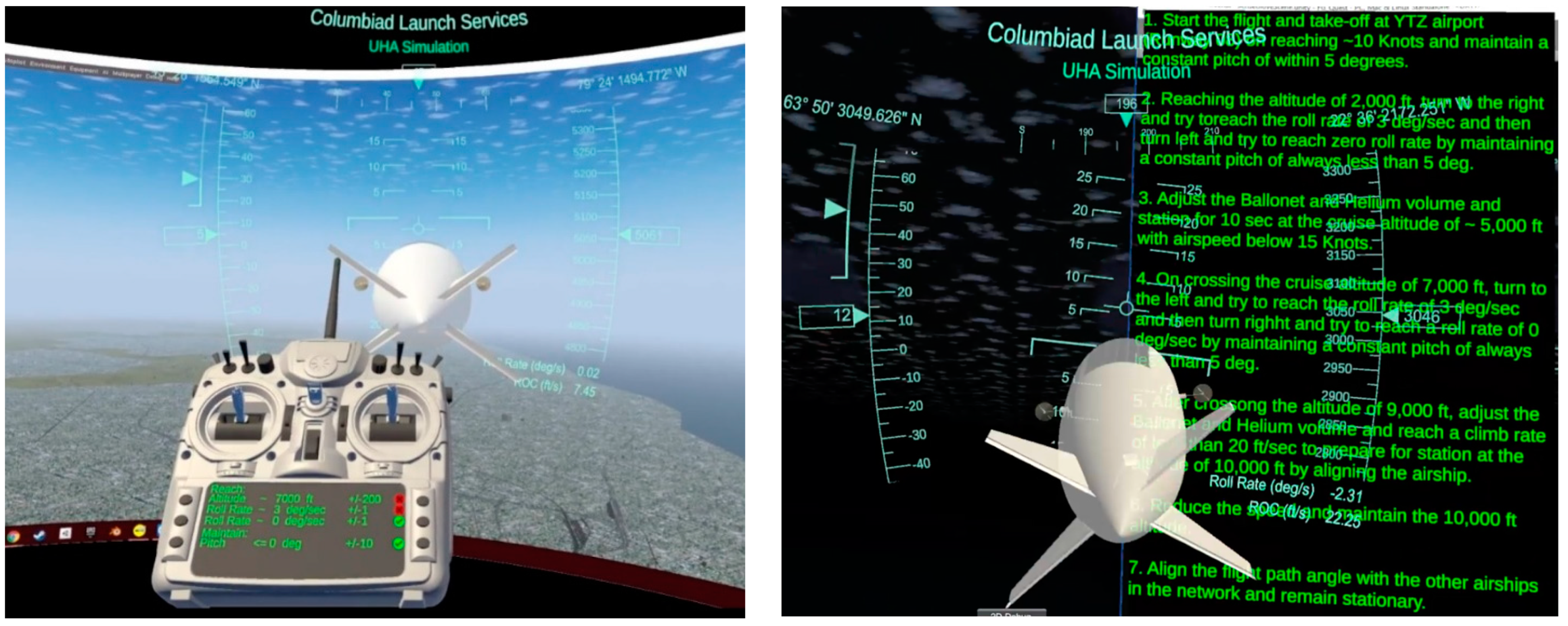
The test subjects were tested on three different scenarios with 10 different users while following the same flight path. All participants in the test were amateur users with limited experience using VR headsets and flight simulation tools. In the first test case, the test subjects flew the airship with the desktop flight simulator. Secondly, the test subjects flew the airship via the VR-HMD flight simulator equipped with an internal HUD. Finally, the test subjects flew the airship via the VR-HMD flight simulator equipped with an internal HUD that tracked the remote controller motions along with test procedure projection on the screen of the virtual FrSky controller. As presented in Figure 11, the test procedure was also shown on the screen of the virtual FrSky controller and the VR screen to let users know about each step of the test well ahead of time. For all cases, the operator’s feedback was recorded.
Upon completing the flight tests, participants’ flight test results were recorded, and they were requested to fill out the NASA TLX rating scale forms along with their feedback. In the following, the results are tabulated based on their respective flight tests for further analysis. It should be noted that in the following, the results from the VR-HMD flight simulator equipped with an internal HUD are presented as VR-HMD 1 and the VR-HMD flight simulator equipped with the internal HUD that tracked the remote controller motions along with test procedure projection on the screen of the virtual FrSky controller is described as VR-HMD 2.
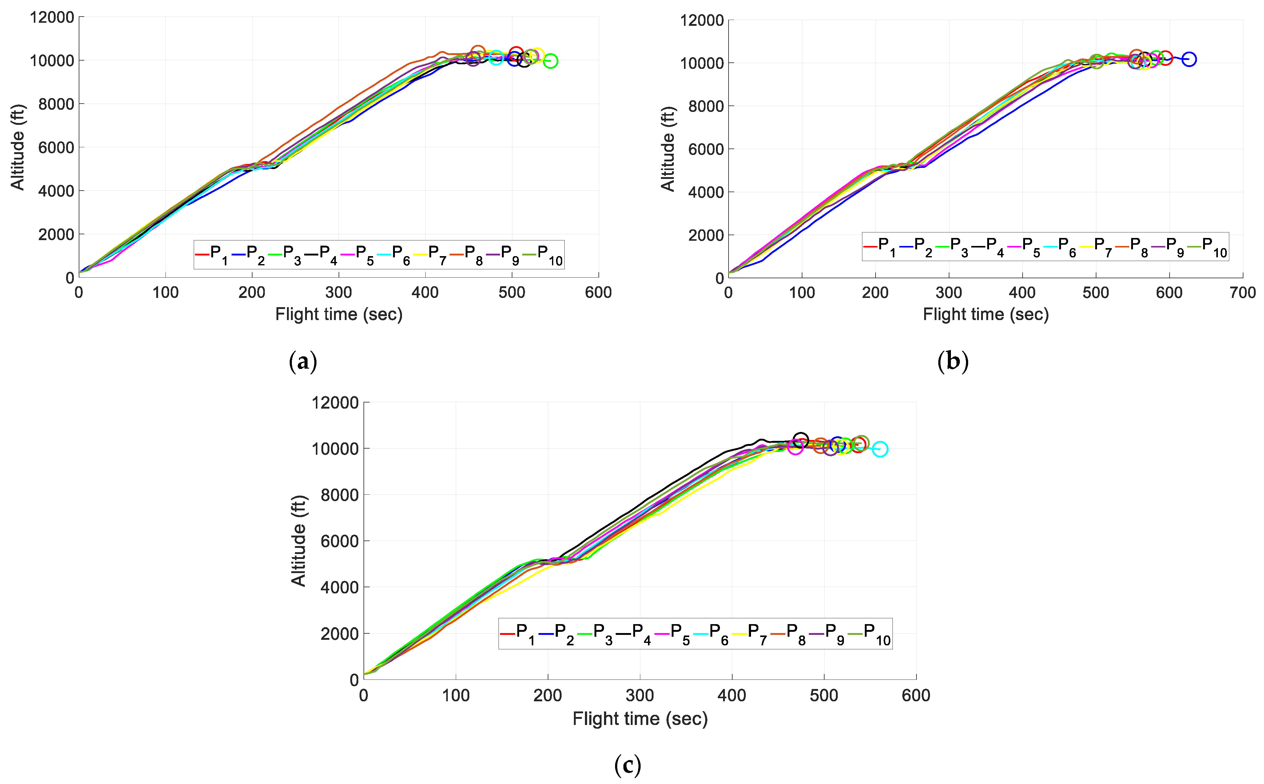
Figure 12 presents the altitude versus flight time for each participant. As can be seen, all participants were able to fly the airship at proper altitude and maintain flight plan requirements. However, the required time to accomplish the flight plan for the VR-HMD 1 simulator was higher than the desktop simulator and the VR-HMD 2 simulator. The end time of each flight scenario for pilots is distinguished in Figure 12 using a circle marker.
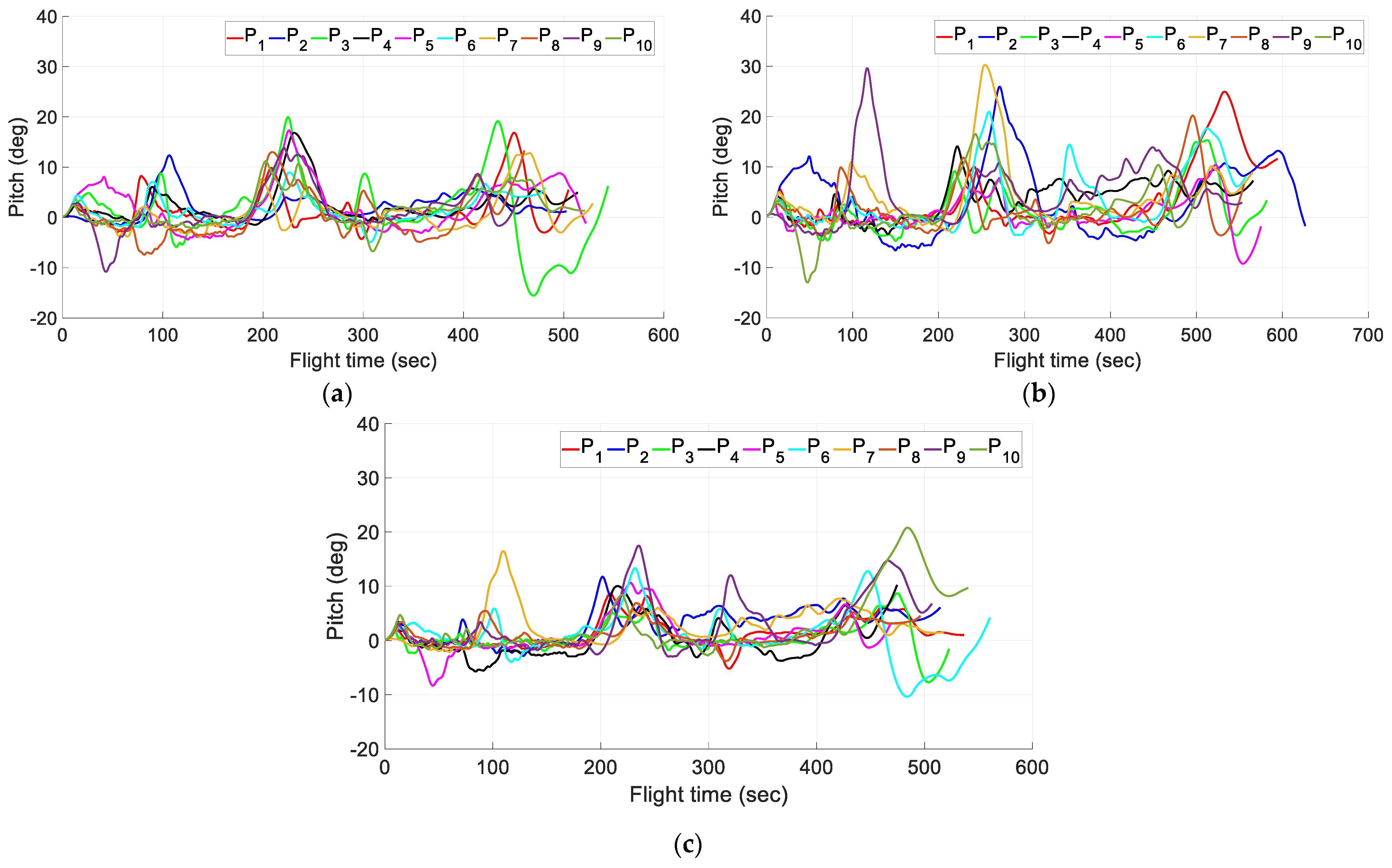
Figure 13 presents the pitch angle versus flight time for each participant. As can be seen, users had better performance while operating the VR-HMD 2 simulator and the desktop simulator compared to the VR-HMD 1 simulator. For the case of the VR-HMD_1 simulator, the resulting pitch reached almost 30 degrees in some cases, which was much higher than the cases reported for the desktop flight simulator and the VR-HMD_2. Users were expected to maintain a value below 5 degrees for the pitch angle. However, during the second phase of the flight test plan and during the fourth phase, where the users were supposed to maintain the required roll rate, most of them struggled with maintaining the pitch requirements up to 5 degrees. The main reason for defining this scenario was to study the user behavior in multi-tasking scenarios and challenge their capabilities and mental/physical demands, which are presented in the next step.
Figure 14 presents the roll rate versus flight time for each participant. The users were supposed to reach a roll rate of 3 deg/sec at certain altitudes to calculate any significant difference that may affect the overall flight safety. As can be seen, almost all participants were able to maintain the flight plan requirements. However, as can be seen in Figure 13, not all of them were able to maintain the required pitch below 5 degrees at all times.
Figure 15 presents the ground airspeed versus flight time for each user. The participants were supposed to maintain different ground speed values at certain altitudes to complete the flight plan. The participants were supposed to remain below 15 knots, reaching an altitude of 15,000 ft, and, as can be seen in Figure 15, all pilots were able to maintain the required ground speed limit.
Finally, Figure 16 presents the rate of climb versus flight time for each user. The participants were supposed to maintain the desired altitudes at each phase of the flight plan while controlling the rate of height change as well. As can be seen, some pilots were struggling with maintaining the required rate of climb using VR-HMD_1, as a higher demand was required to complete the flight plan using this method. This is supported by the results reported in the following for the NASA TLX questionnaire, which identifies the pilots’ available mental capacity.
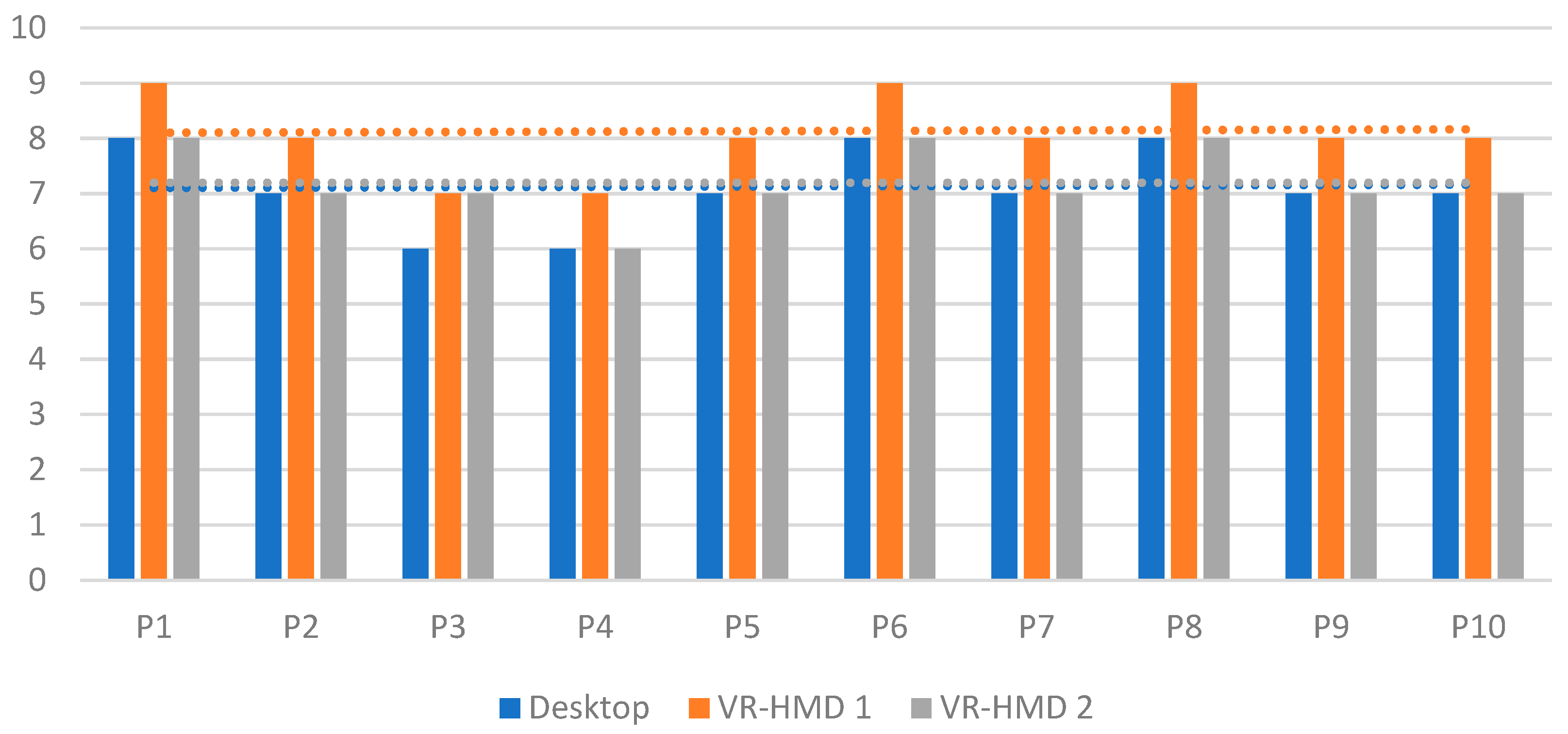
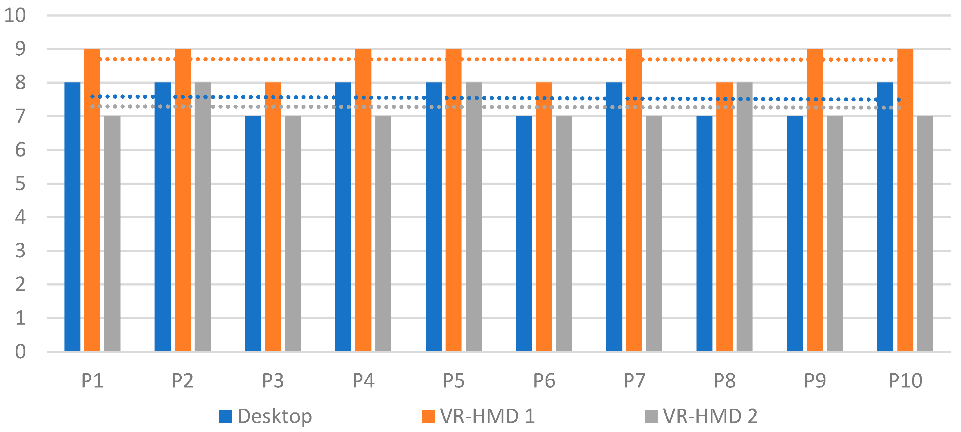
The mental workload experienced by all the participants during all three flight tests is shown in Figure 17. The mental workload seems to be high among participants using the VR-HMD 1 simulator compared to the desktop simulator and the VR-HMD 2 simulator. Additionally, the HOD decreases the mental workload in most of the participants. The main reason for the reduction in mental workload could be due to the test procedure projection on the screen of the virtual FrSky controller, which helps the user have a step-by-step guideline. The dotted lines show the average values for each method.
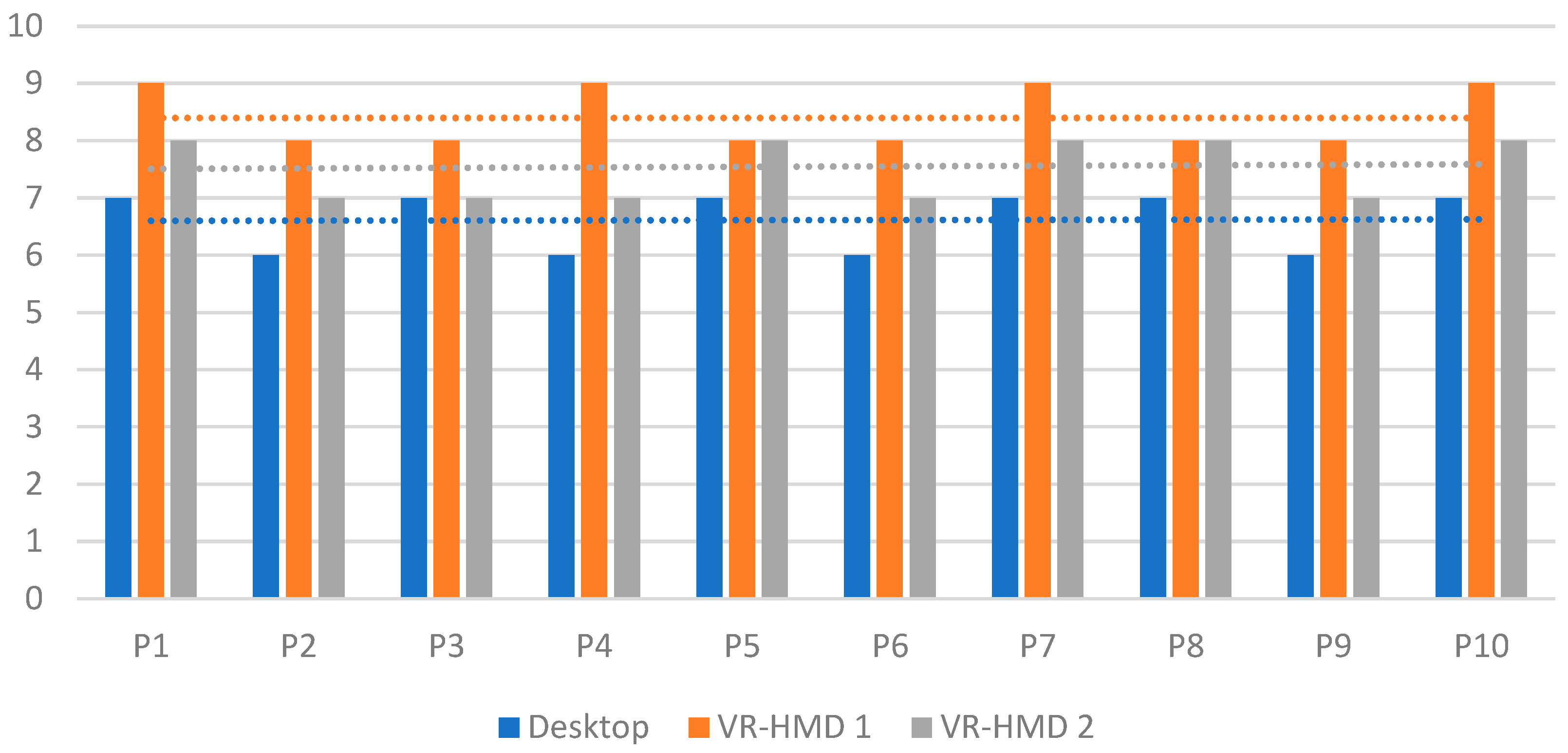
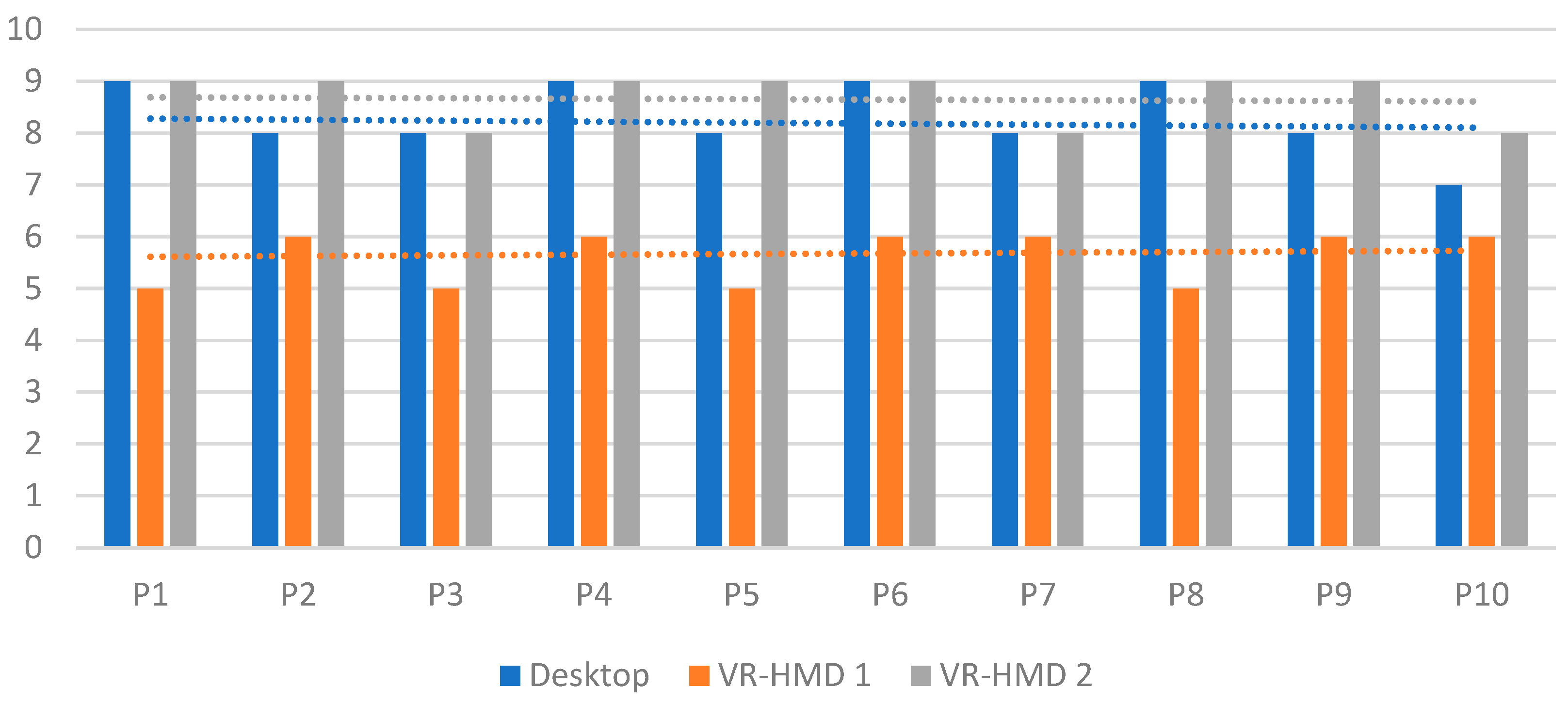
Figure 18 presents the physical demand experienced by all the participants during the three flight tests. Similar to mental workload, the physical demand seems to be highest among participants using the VR-HMD 1 simulator compared to the desktop and VR-HMD 2 simulators. The dotted lines present the average values for each method.
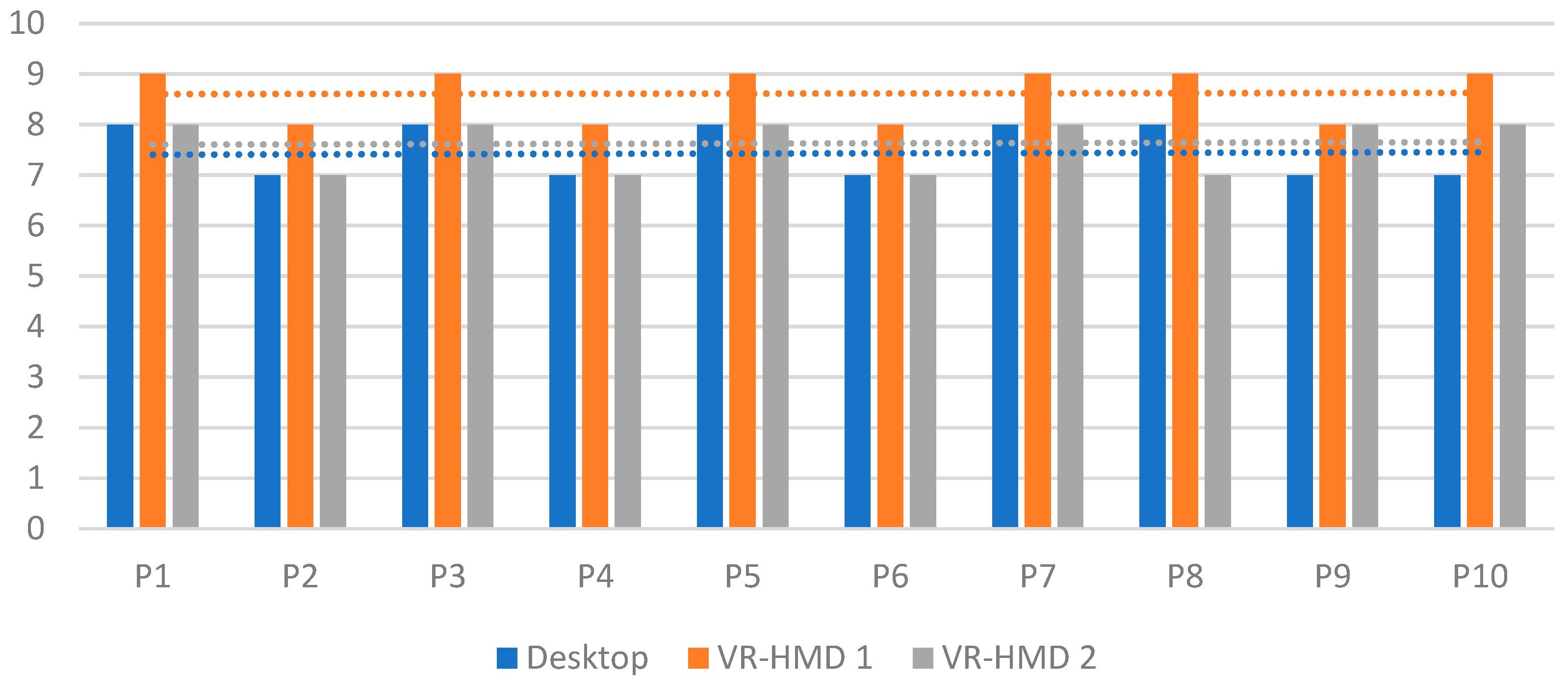
Figure 19 depicts the overall temporal demand experienced by the participants during the three flight tests. The flight plan was carefully designed not to exert any sense of rush on the participants. Additionally, they were reminded to complete the tasks in their own time during the pre-flight briefing. The average amount of rush experienced by the participants using the desktop and VR-HMD 1 simulators was higher than that for the VR-HMD 2 simulator. The dotted lines show the average values for each method.
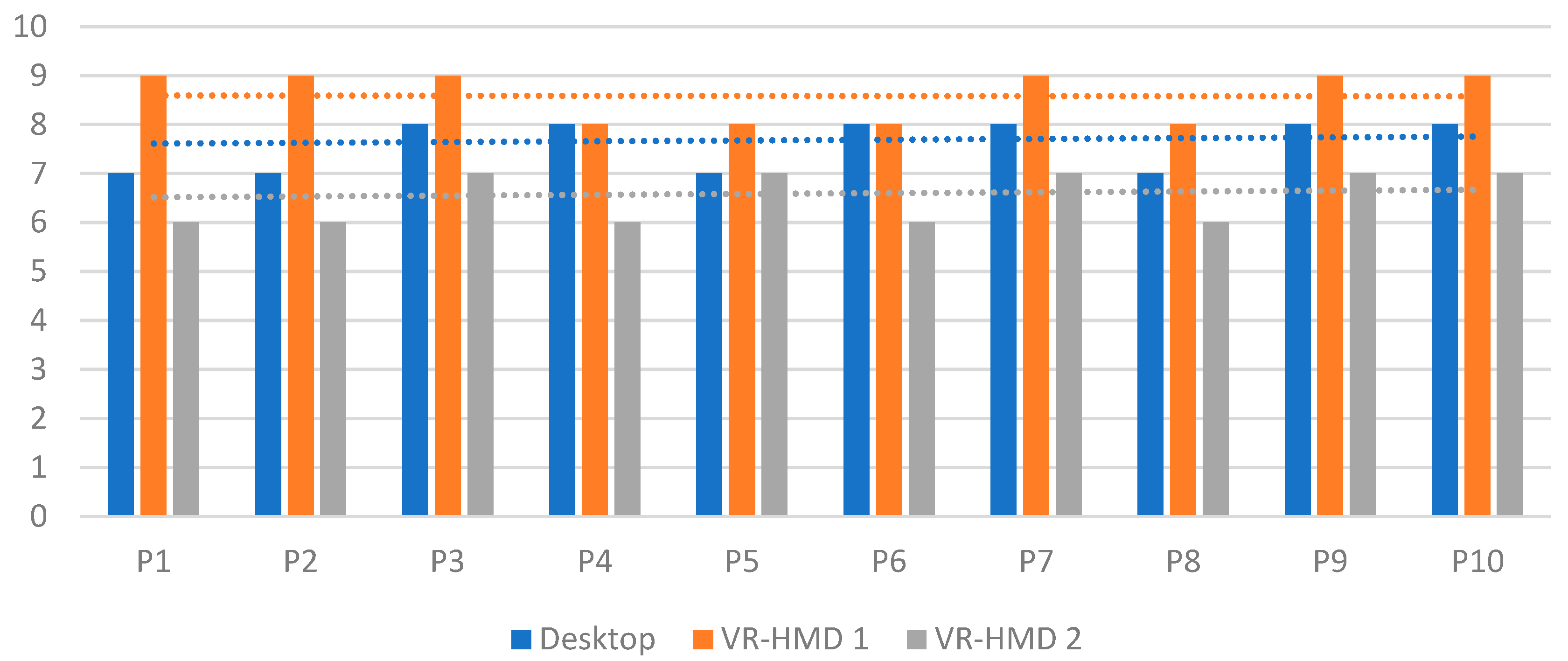
In the next step, the participants were asked to rate their performance on a scale of 1 to 10. Their performance rating could depend on their ability to maneuver the airship properly, follow the flight path and station-keep. As can be seen in Figure 20, the participants performed well when using the VR-HMD 2 and desktop simulators compared to the VR-HMD 1 simulator.
Figure 21 presents the amount of effort required to complete the flight test using the different methods. As expected, the effort needed to accomplish the flight test procedure using the desktop and VR-HMD 2 simulators was less than that for the VR-HMD 1 simulator. The dotted lines present the average values for each method.
Finally, the participants were asked to rank the amount of frustration experienced while using all three different methods, and the results are graphed in Figure 22. The participants reported the lowest frustration values for VR-HMD 2 compared to the other two methods. The dotted lines show the average values for each method.
Further Developments
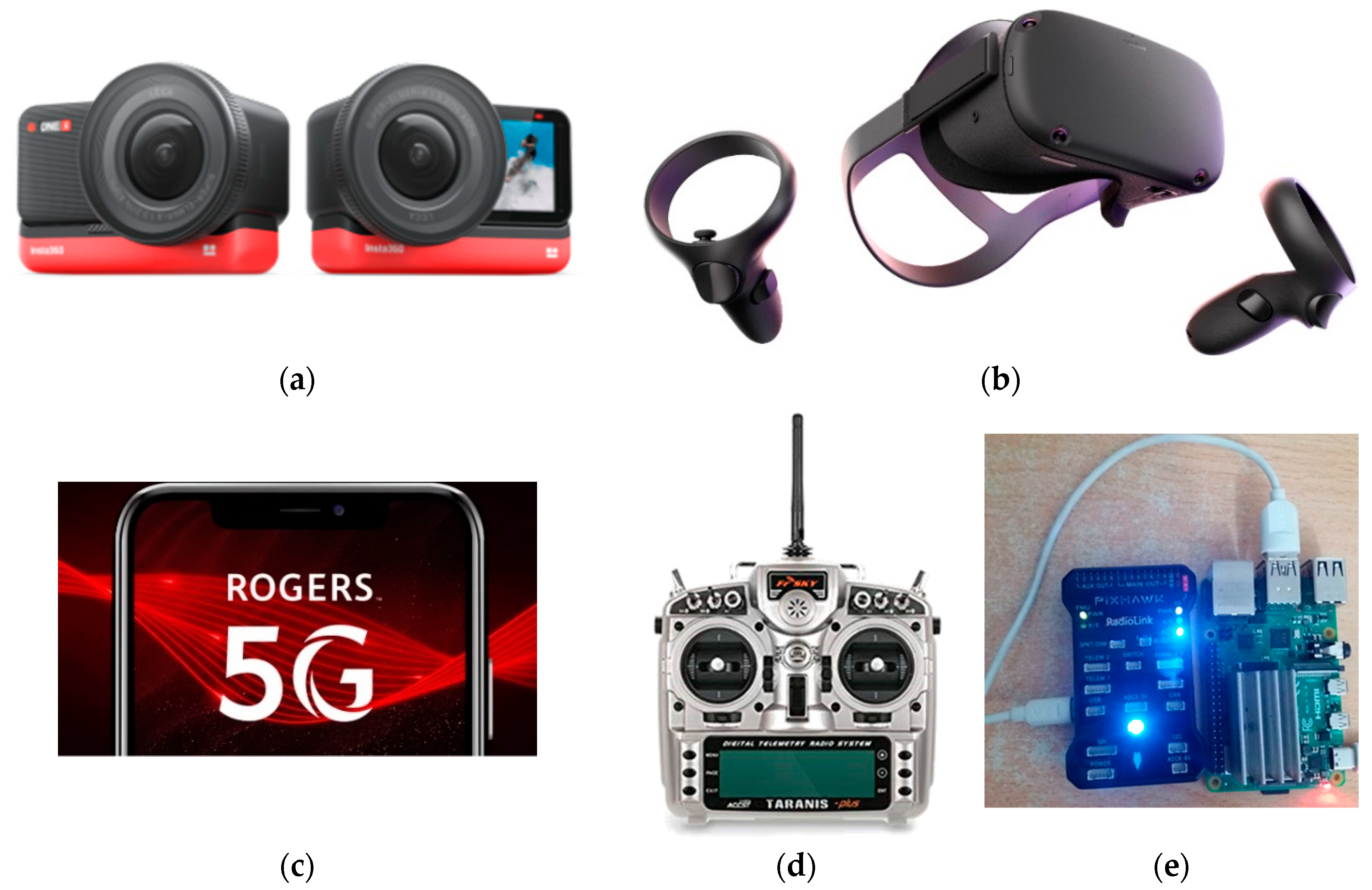
The proposed VR-HMD flight simulator can also be seen as a GCS system, and as shown in Figure 23, it is conceived to fully define the GCS concept and transmit flight information as well as POV visuals in real time via the actual images broadcast by the onboard video cameras. Accordingly, the same concept developed for the VR-HMD simulator may be used for the VR-HMD GCS. A 360-degree camera (Insta360, Irvine, CA, USA) of some sort, as shown in Figure 23a, to allow a VR-oriented view for the GCS may be integrated with the Raspberry PI (Raspberry Pi Foundation, Cambridge, England, UK) and Pixhawk (Pixhawk by Auterion, Zürich, Switzerland) shown in Figure 23e using the available 4G/5G network. The VR-HMD simulator allows pilots to accomplish a part of real flight tests with the same data transmission techniques used in the simulated environment. In addition, the development of the VR-HMD GCS may be enhanced by using an AR headset to visualize augmented flight using a first-person POV or a third-person POV such as the one shown in Figure 7 with the use of a graphical model of the actual airship. Furthermore, haptics and gloves may be integrated with the VR/AR-HMD GCS to increase situational awareness of the pilot in BLOS scenarios. Our current focus is to use the latest technology in the field to enhance the command-and-control station systems and move towards the goal of transition from simulated training to actual flight with a single unified system.
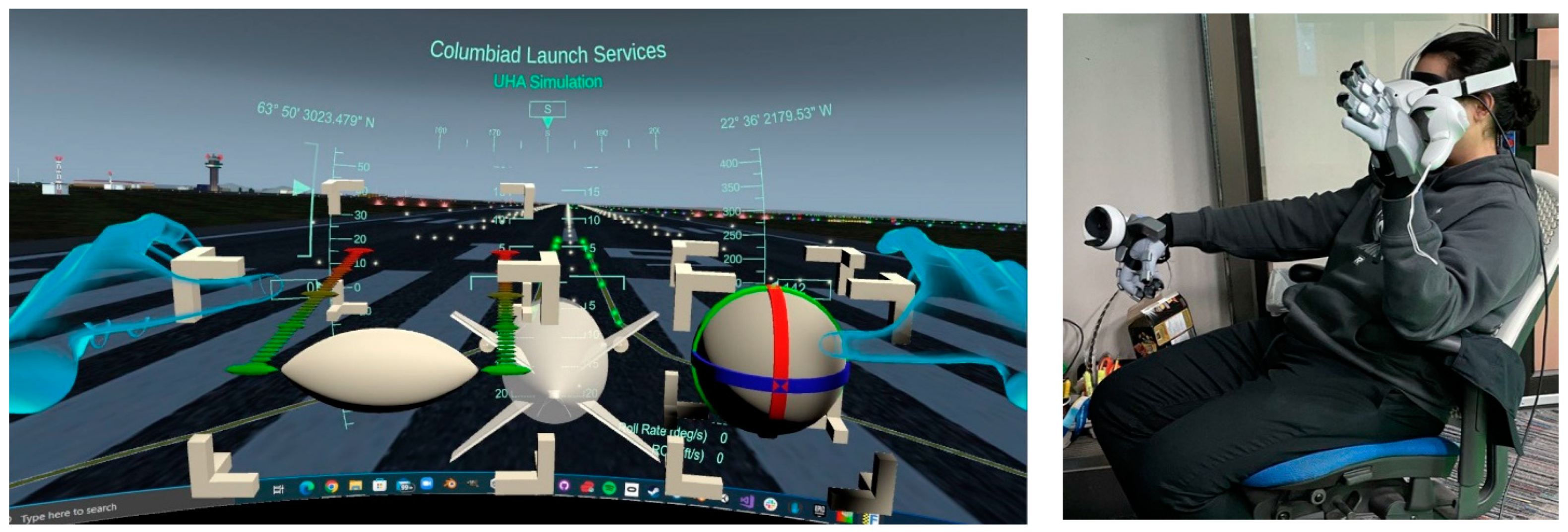
Utilizing haptic sense in the proposed flight simulation tool can enhance the current work. The term “haptics” was proposed by Revesz in 1950, after observing blind performance and referring to an unconventional experience rather than traditional methods of touch and kinesthesis. More specifically, this term means “active touch” rather than passive touching [33,34]. For the next step, we want to incorporate haptic gloves to control the aerial vehicle with the use of a virtual controller defined within the virtual environment. The stand-alone VR headset will be connected to the haptics and the flight simulation tool. The VR headset will be used to visualize basic flight simulation while the vehicle could be controlled via the haptic gloves and a virtual controller defined within the virtual environment. Figure 24 shows the initial haptic-based VR flight simulator where a pair of SenseGlove Nova Gloves (SenseGlove, Delft, The Netherlands) were connected with a VR Oculus Quest and its controller to control the airship via a virtual roll/pitch/yaw controller and a throttle. Initial results showed a significant decrease in the amount of physical and mental demand required by the users during flight.
4. Conclusions
This paper describes a system that can connect a flight simulator to a wireless VR-HMD and transmit simulated flight information as well as POV visuals in real time. The purpose of such a system was to test the flight of stratospheric airships in BLOS scenarios. In this work, a desktop flight simulator was developed using the scaled-down geometry of an airship designed for stratospheric applications along with the corresponding aerodynamics and other characteristics of the aircraft in the FlightGear flight simulator. Moreover, the control surfaces were connected with a FrSky Taranis X9 radio transmitter. The VR-HMD streamed the flight environment and enhanced the design procedure of the stratospheric airship via the simulation tool. Our results showed that the VR-HMD flight simulator equipped with the internal HUD that tracked the remote controller motions along with the test procedure projection on the screen of the digital twin of the FrSky controller showed better performance, less effort, less temporal demand and less frustration compared to the desktop flight simulator. The current iteration of the system is ideal to train pilots using similar systems in a safe and immersive environment. The proposed VR-HMD flight simulator may also be seen as a GCS prototype, and it was conceived to define the GCS concept and transmit flight information as well as POV visuals in real time via the real images broadcast using an onboard camera. Additionally, incorporating haptic sense into the proposed flight simulation tool may enhance the current study to lower the physical and mental demand during flight.
Author Contributions
Conceptualization, M.R. and J.C.; Methodology, M.R., J.K., P.P. and J.C.; Software, M.R. and J.K.; Formal analysis, M.R. and J.K.; Writing—original draft, M.R.; Preparation, M.R.; Data curation, J.K.; Writing—review and editing, J.K., P.P. and J.C. All authors have read and agreed to the published version of the manuscript.
Funding
This work was funded by Mitacs through the Mitacs Accelerate Program (reference number: IT16648) and Columbiad Launch Services Inc.
Data Availability Statement
Not applicable.
Conflicts of Interest
The authors declare no conflict of interest.
Nomenclature
| Roman Symbols | |
| Coefficient in denominator of the transfer function | |
| a | Distance from aerodynamic center to the center of gravity |
| Coefficient in denominator of the transfer function | |
| b | Distance from the aerodynamic center to the center of buoyancy |
| C | Control forces and moments |
| d | Rate of change of thrust position in x, y and z direction |
| Acceleration of gravity | |
| Airplane moments of inertia about X | |
| Airplane product of inertia about Z | |
| Airplane moment of inertia about Z | |
| Roll angular acceleration per unit roll angle | |
| Roll angular acceleration per unit yaw rate | |
| Roll angular acceleration per unit sideslip angle | |
| Roll angular acceleration per unit control surface angle | |
| M | Mass matrix |
| Airplane mass | |
| Yaw angular acceleration per unit roll rate | |
| Yaw angular acceleration per unit yaw rate | |
| Yaw angular acceleration per unit sideslip angle (due to thrust) | |
| Yaw angular acceleration per unit sideslip angle | |
| Yaw angular acceleration per unit control surface angle | |
| P | Power contribution, propulsion forces and moments |
| Perturbed value of airplane angular velocity about X | |
| Rate of change of perturbed value of airplane bank angle | |
| Perturbed value of airplane angular velocity about Y | |
| Rate of change of perturbed value of airplane pitch angle | |
| Perturbed value of airplane angular velocity about Z | |
| Rate of change of perturbed value of airplane heading angle | |
| Reference area | |
| s | Laplace domain variable |
| T | Thrust of the airship |
| t | Time |
| Velocity component along X direction | |
| u | Velocity component along X direction |
| v | Velocity component along Y direction |
| w | Velocity component along Z direction |
| Lateral acceleration per unit roll rate | |
| Lateral acceleration per unit yaw rate | |
| Lateral acceleration per unit sideslip angle | |
| Lateral acceleration per unit control surface angle | |
| Greek Symbols | |
| Angle of sideslip | |
| Control surface deflection angle | |
| Rudder deflection angle | |
| Pitch angle | |
| Air density | |
| Thrust incidence | |
| Perturbed value of airplane bank angle | |
| Perturbed value of airplane heading angle | |
References
- Santos, J.S.A.; Góes, L.C.S.; Pant, R.S. Design and Flight Testing of an Autonomous Airship. In Proceedings of the 22nd AIAA Lighter-Than-Air Systems Technology Conference, Dallas, TX, USA, 22–26 June 2015. [Google Scholar] [CrossRef]
- Smith, I.S. HiSentinel & Stratospheric Airship Design Sensitivity. Southwest Research Institute, KISS Workshop. 2013. Available online: https://kiss.caltech.edu/workshops/airships/presentations/smith.pdf (accessed on 19 September 2021).
- Sceye. Sceye|A New Generation of HAPS|High Altitude Platform Stations. 2021. Available online: https://www.sceye.com/ (accessed on 25 August 2021).
- Lobner, P. DARPA Integrated Sensor Is Structure (ISIS) Airship. 2020. Available online: https://lynceans.org/wp-content/uploads/2020/12/DARPA-LM_ISIS.pdf (accessed on 25 August 2021).
- Stavros, A. Lockheed Martin Lighter-Than-Air Programs Lockheed Martin Lighter-Than-Air Technologies. (May). 2013. Available online: https://kiss.caltech.edu/workshops/airships/presentations/horvarter.pdf (accessed on 19 September 2021).
- Thales. What’s up with Stratobus. 2017. Available online: https://www.thalesgroup.com/en/worldwide/space/news/whats-stratobus (accessed on 25 August 2021).
- Chakraborty, I.; Ahuja, V.; Comer, A.; Mulekar, O. Development of a modeling, flight simulation, and control analysis capability for novel vehicle configurations. In Proceedings of the AIAA Aviation 2019 Forum, Dallas, TX, USA, 17–21 June 2019; pp. 1–24. [Google Scholar] [CrossRef]
- Melin, T.; Uyoga, D. Formation Flight Mechanics and its Integrated Logistics. Transp. Res. Procedia 2018, 29, 233–243. [Google Scholar] [CrossRef]
- Martins, L.S.N. Development of a Flight Simulation Training Device and Remote Pilot Station: The URBLOG Unmanned Hybrid Airship Vehicle Case; Universidade Beira Interior: Covilhã, Portugal, 2020. [Google Scholar]
- Schaffernak, H.; Moesl, B.; Vorraber, W.; Koglbauer, I.V. Potential Augmented Reality Application Areas for Pilot Education: An Exploratory Study. Educ. Sci. 2020, 10, 86. [Google Scholar] [CrossRef] [Green Version]
- Oberhauser, M.; Dreyer, D.; Braunstingl, R.; Koglbauer, I. What’s Real About Virtual Reality Flight Simulation? Comparing the Fidelity of a Virtual Reality with a Conventional Flight Simulation Environment. Aviat. Psychol. Appl. Hum. Factors 2018, 8, 22–34. [Google Scholar] [CrossRef]
- Oberhauser, M.; Dreyer, D. A virtual reality flight simulator for human factors engineering. Cogn. Technol. Work. 2017, 19, 263–277. [Google Scholar] [CrossRef]
- Cross, J.I.; Boag-Hodgson, C.; Ryley, T.; Mavin, T.; Potter, L.E. Using Extended Reality in Flight Simulators: A Literature Review. IEEE Trans. Vis. Comput. Graph. 2022; ahead of print. [Google Scholar] [CrossRef]
- Ernst, J.M.; Ebrecht, L.; Schmerwitz, S. Virtual cockpit instruments displayed on head-worn displays—Capabilities for future cockpit design. In Proceedings of the AIAA/IEEE Digital Avionics Systems Conference, San Diego, CA, USA, 8–12 September 2019. [Google Scholar] [CrossRef]
- McGowin, G.; Xi, Z.; Newton, O.B.; Sukthankar, G.; Fiore, S.M.; Oden, K. Examining Enhanced Learning Diagnostics in Virtual Reality Flight Trainers. Proc. Hum. Factors Ergon. Soc. Annu. Meet. 2020, 64, 1476–1480. [Google Scholar] [CrossRef]
- Rauschnabel, P.A.; Felix, R.; Hinsch, C.; Shahab, H.; Alt, F. What is XR? Towards a Framework for Augmented and Virtual Reality. Comput. Hum. Behav. 2022, 133, 107289. [Google Scholar] [CrossRef]
- Mütterlein, J. The three pillars of virtual reality? Investigating the roles of immersion, presence, and interactivity. In Proceedings of the Annual Hawaii International Conference on System Sciences, Hilton Waikoloa Village, HI, USA, 3–6 January 2018; pp. 1407–1415. [Google Scholar] [CrossRef] [Green Version]
- Kamoonpuri, J.M. Development of a 3D Holographic Flight Situational Awareness System. BSc Thesis, Department of Aerospace Engineering, Ryerson University, Toronto, ON, Canada, 2020. Available online: https://digital.library.ryerson.ca/islandora/object/RULA%3A8752/datastream/OBJ/view (accessed on 25 August 2021).
- Halim, I.; Casey, J.; Baghaei, N. Designing a virtual reality flight simulator. In Proceedings of the ICCE 2018—26th International Conference on Computers in Education, Main Conference Proceedings, Manila, Philippines, 26–30 November 2018; pp. 518–520. [Google Scholar]
- Pradhan, P.; Chung, J.; Chittaluri, V.; Park, H.U. Development of Holographic User Interface for UAV Ground Control Using Microsoft Hololens. In Proceedings of the 63rd Aeronautics Conference, Chicago, IL, USA, 21–24 June 2017; pp. 1–8. [Google Scholar]
- Auer, S.; Gerken, J.; Reiterer, H.; Jetter, H. Comparison Between Virtual Reality and Physical Flight Simulators for Cockpit Familiarization. In Proceedings of the Mensch und Computer, Ingolstadt, Germany, 5–8 September 2021; pp. 378–392. [Google Scholar] [CrossRef]
- Aukstakalnis, S. Practical Augmented Reality: A Guide to the Technologies, Applications, and Human Factors for AR and VR; Addison-Wesley Professional: Boston, MA, USA, 2017; Available online: http://ezproxy.lib.ryerson.ca/login?url=https://search.ebscohost.com/login.aspx?direct=true&db=nlebk&AN=1601678&site=ehost-live (accessed on 25 August 2021).
- Safi, M.; Chung, J.; Pradhan, P. Review of augmented reality in aerospace industry. Aircr. Eng. Aerosp. Technol. 2019, 91, 1187–1194. [Google Scholar] [CrossRef]
- Parrish, K. Japan Airlines is Slapping HoloLens Onto Mechanics and Flight Crew Students for Paper-Free Training. 2016. Available online: https://www.digitaltrends.com/virtual-reality/hololens-japanese-airline-training/ (accessed on 25 June 2021).
- Pradhan, P.; Chung, J. Development and Evaluation of Flight Deck using Augmented Reality. In Proceedings of the CASI AERO 2021 Conference, Toronto, ON, Canada, 14–18 June 2021. [Google Scholar]
- Pradhan, P.; Chung, J. Augmented Reality Cockpit Display System in Real-Time Flight Simulation Environment; Ryerson University: Toronto, ON, Canada, 2019. [Google Scholar]
- VRcompare. VRcompare—The Internet’s Largest VR & AR Headset Database. 2021. Available online: https://vr-compare.com/ (accessed on 25 June 2021).
- Rostami, M.; Chung, J. Multidisciplinary Analysis Program for Light Aircraft (MAPLA). In Proceedings of the Canadian Society for Mechanical Engineering International Congress, Charlottetown, PE, Canada, 27–30 June 2021. [Google Scholar]
- Berndt, J.S. JSBSim, An Open Source, Platform-Independent, Flight Dynamics Model in C++; The JSBSim Development Team: Houston, TX, USA, 2011. [Google Scholar]
- Rostami, M.; Chung, J.; Park, H.U. Design optimization of multi-objective proportional–integral–derivative controllers for enhanced handling quality of a twin-engine, propeller-driven airplane. Adv. Mech. Eng. 2020, 12, 1687814020923178. [Google Scholar] [CrossRef]
- Cook, M.V. The Linearised Small Perturbation Equations of Motion for an Airship. 1990. Available online: https://hdl.handle.net/1826/1482 (accessed on 1 May 2020).
- Stengel, R. Flight Dynamics, 1st ed.; Princeton University Press: Princeton, NJ, USA, 2004. [Google Scholar]
- Robles-De-La-Torre, G. The importance of the sense of touch in virtual and real environments. IEEE Multimed. 2016, 13, 24–34. [Google Scholar] [CrossRef]
- Srinivasan, M.A. Haptic Interfaces, In Virtual Reality: Scientific and Technical Challenges. In Report of the Committee on Virtual Reality Research and Development; The National Academies Press, Computer Science and Telecommunications Board: Washington, DC, USA, 1995. [Google Scholar]
Figure 2.
The airship model equipped with two electrical engines.

Figure 3.
Side, back and top view of the airship geometry.

Figure 4.
Required sub-sections to construct the flight simulation module.

Figure 5.
HUD elements were presented on the screen of the FGFS to increase pilots’ situational awareness.
Figure 5.
HUD elements were presented on the screen of the FGFS to increase pilots’ situational awareness.

Figure 6.
Simplified flowchart describing the process of displaying real-time flight information from a PC-based flight simulator on a wireless VR-HMD.
Figure 6.
Simplified flowchart describing the process of displaying real-time flight information from a PC-based flight simulator on a wireless VR-HMD.

Figure 7.
View from within the Oculus Quest running the simulator.

Figure 8.
Data import GUI used to set up data from FlightGear in the simulation.

Figure 9.
Close-up of the heading tape on the head-locked HUD.

Figure 10.
Different camera views within the flight simulator developed using the FGFS.

Figure 11.
Test procedure that was shown on the virtual RC controller screen and VR screen to let users know about each step.
Figure 11.
Test procedure that was shown on the virtual RC controller screen and VR screen to let users know about each step.

Figure 12.
Recorded data for the altitude against the flight time for different pilots. (a) Desktop flight simulator; (b) VR-HMD 1 simulator; (c) VR-HMD 2 simulator.
Figure 12.
Recorded data for the altitude against the flight time for different pilots. (a) Desktop flight simulator; (b) VR-HMD 1 simulator; (c) VR-HMD 2 simulator.

Figure 13.
Recorded data for the pitch angle against the flight time for different pilots. (a) Desktop flight simulator; (b) VR-HMD 1 simulator; (c) VR-HMD 2 simulator.
Figure 13.
Recorded data for the pitch angle against the flight time for different pilots. (a) Desktop flight simulator; (b) VR-HMD 1 simulator; (c) VR-HMD 2 simulator.

Figure 14.
Recorded data for the roll rate against the flight time for different pilots. (a) Desktop flight simulator; (b) VR-HMD 1 simulator; (c) VR-HMD 2 simulator.
Figure 14.
Recorded data for the roll rate against the flight time for different pilots. (a) Desktop flight simulator; (b) VR-HMD 1 simulator; (c) VR-HMD 2 simulator.

Figure 15.
Recorded data for the ground airspeed against the flight time for different pilots. (a) Desktop flight simulator; (b) VR-HMD 1 simulator; (c) VR-HMD 2 simulator.
Figure 15.
Recorded data for the ground airspeed against the flight time for different pilots. (a) Desktop flight simulator; (b) VR-HMD 1 simulator; (c) VR-HMD 2 simulator.

Figure 16.
Recorded data for the rate of climb against the flight time for different pilots. (a) Desktop flight simulator; (b) VR-HMD 1 simulator; (c) VR-HMD 2 simulator.
Figure 16.
Recorded data for the rate of climb against the flight time for different pilots. (a) Desktop flight simulator; (b) VR-HMD 1 simulator; (c) VR-HMD 2 simulator.

Figure 17.
Mental demand experienced by all the participants using the three test procedures.

Figure 18.
Physical demand experienced by all the participants using the three test procedures.

Figure 19.
Temporal demand experienced by all the participants using the three test procedures.

Figure 20.
Performance of all the participants using the three test procedures.

Figure 21.
Effort needed by all the participants using the three test procedures.

Figure 22.
Frustration experienced by all the participants using the three test procedures.

Figure 23.
Connecting the VR headset (b) and radio controller (d) with an on-board 360-degree camera (a) and Raspberry PI (e) to obtain the flight data and display them on the VR screen in real time using the 4G/5G network (c).
Figure 23.
Connecting the VR headset (b) and radio controller (d) with an on-board 360-degree camera (a) and Raspberry PI (e) to obtain the flight data and display them on the VR screen in real time using the 4G/5G network (c).

Figure 24.
View from within the Oculus Quest VR running the flight simulator and the actual pilot wearing the SenseGlove Nova set for command and control.
Figure 24.
View from within the Oculus Quest VR running the flight simulator and the actual pilot wearing the SenseGlove Nova set for command and control.


Table 1.
Airship geometry parameters.
| Variable | Value | Description |
|---|---|---|
| dmax | 17 ft | Maximum hull diameter |
| fr | 3.86 | Fineness ratio (lairship/dmax) |
| XCG | 28.9 ft | Center of gravity location from nose |
| XCB | 28.9 ft | Centre of buoyancy location from nose |
| ZCG-CB | 3.28 ft | Vertical distance between CG and CB (CG below CB) |
| lairship | 65.62 ft | Total airship length |
| me | 375 lb | Empty mass |
| Sf | 63.5 ft2 | Fin reference area |
| Sh | 228.2 ft2 | Hull reference area |
| Vol | 10,594.4 ft3 | Hull volume |
| Tmax | 45 lbf | Maximum engine thrust (each) |
Table 2.
The state vectors used in the Euler angle and quaternion simulations [32].
Table 2.
The state vectors used in the Euler angle and quaternion simulations [32].
| Vector | Euler Angle | Quaternion |
|---|---|---|
| X (1) | Body axis x inertial velocity, m/s | Body axis x inertial velocity, m/s |
| X (2) | Body axis y inertial velocity, m/s | Body axis y inertial velocity, m/s |
| X (3) | Body axis z inertial velocity, m/s | Body axis z inertial velocity, m/s |
| X (4) | North position of center of mass WRT Earth, m | North position of center of mass WRT Earth, m |
| X (5) | East position of center of mass WRT Earth, m | East position of center of mass WRT Earth, m |
| X (6) | Negative of CG altitude WRT Earth, m | Negative of CG altitude WRT Earth, m |
| X (7) | Body axis roll rate, rad/s | Body axis roll rate, rad/s |
| X (8) | Body axis pitch rate, rad/s | Body axis pitch rate, rad/s |
| X (9) | Body axis yaw rate, rad/s | Body axis yaw rate, rad/s |
| X (10) | Roll angle of body WRT Earth, rad | q1, x component of quaternion |
| X (11) | Pitch angle of body WRT Earth, rad | q2, x component of quaternion |
| X (12) | Yaw angle of body WRT Earth, rad | q3, x component of quaternion |
| X (13) | NA | q4, cos (Euler) component of quaternion |
Table 3.
Flight variables under consideration.
| Variable (Unit) | Description |
|---|---|
| Time (s) | Helps in calculating the time taken by the user to accomplish the test phase. |
| Ground Airspeed (knots) | As speed plays an important factor throughout the flight phase, it is helpful to determine any unsafe conditions (loss of control due to a reduction in speed) that could lead the airship into an accident. |
| Altitude (ft) | Gives a realistic idea about the flight regime and the user’s ability to fly the airship at proper altitude to avoid any unsafe conditions (collision with terrain). |
| Rate of Climb (ft/s) | It is important to understand the rate of change of height while performing each step of the proposed test procedure. |
| Roll Rate (deg/s) | Helps to evaluate the difference between the flight plan and the user’s performance to calculate any significant difference that may affect the overall flight safety. |
| Pitch Angle (deg) | As an essential parameter that aids in providing stall information to the pilot, this is useful to evaluate pilot performance. |
Disclaimer/Publisher’s Note: The statements, opinions and data contained in all publications are solely those of the individual author(s) and contributor(s) and not of MDPI and/or the editor(s). MDPI and/or the editor(s) disclaim responsibility for any injury to people or property resulting from any ideas, methods, instructions or products referred to in the content. |
© 2023 by the authors. Licensee MDPI, Basel, Switzerland. This article is an open access article distributed under the terms and conditions of the Creative Commons Attribution (CC BY) license (https://creativecommons.org/licenses/by/4.0/).
Share and Cite
MDPI and ACS Style
Rostami, M.; Kamoonpuri, J.; Pradhan, P.; Chung, J. Development and Evaluation of an Enhanced Virtual Reality Flight Simulation Tool for Airships. Aerospace 2023, 10, 457. https://doi.org/10.3390/aerospace10050457
AMA Style
Rostami M, Kamoonpuri J, Pradhan P, Chung J. Development and Evaluation of an Enhanced Virtual Reality Flight Simulation Tool for Airships. Aerospace. 2023; 10(5):457. https://doi.org/10.3390/aerospace10050457
Chicago/Turabian StyleRostami, Mohsen, Jafer Kamoonpuri, Pratik Pradhan, and Joon Chung. 2023. "Development and Evaluation of an Enhanced Virtual Reality Flight Simulation Tool for Airships" Aerospace 10, no. 5: 457. https://doi.org/10.3390/aerospace10050457
Note that from the first issue of 2016, this journal uses article numbers instead of page numbers. See further details here.