
Thrust-Based Stabilization and Guidance for Airships without Thrust-Vectoring

1
Dipartimento di Scienze e Tecnologie Aerospaziali, Politecnico di Milano, 20156 Milan, Italy
2
PACE Aerospace & IT GmbH, 14059 Berlin, Germany
*
Author to whom correspondence should be addressed.
Aerospace 2023, 10(4), 344; https://doi.org/10.3390/aerospace10040344
Submission received: 21 February 2023
/
Revised: 23 March 2023
/
Accepted: 29 March 2023
/
Published: 2 April 2023
(This article belongs to the Special Issue Mission Analysis and Design of Lighter-than-Air Flying Vehicles)
Abstract
:The concept of thrust-based control without the employment of thrust-vectoring (TVC), already introduced in a previous work by the authors, is further developed in conjunction with an appropriate control suite, tasked with both artificial stabilization and beam-tracking navigation functions. In the paper, the fully non-linear mathematical model employed for testing the controllers in a virtual environment is outlined. Then a comparative approach is adopted in the analysis, where a standard tail-back airship with deflectable aerodynamic surfaces is employed as a baseline, and the performance of a four-thrusters layout with a thrust-based control and no TVC is assessed with respect to it. Featured test cases in forward flight include short climbs, abrupt turns, and multi-checkpoint navigation. The research supports the feasibility and adequate performance of the proposed thrust-based airship layout and control, and presents a critical analysis of the pros and cons with respect to the considered baseline airship configuration featuring standard aerodynamic control.
Keywords:
flight dynamics; airship; high-altituda airship (HAA); unmanned aerial vehicle (UAV); autonomous flight; lighter-than-air (LTA); stability augmentation system (SAS); thrust-based stabilization; guidance; navigation; thrust-based guidance; control surfaces; airship design; control design; thrust vector control (TVC)1. Introduction
The employment of lighter-than-air (LTA) platforms for autonomous flight missions is attracting the interest of the scientific and industrial communities, thanks primarily to the increased flight endurance of such flying vehicles, starkly above that of current rotary-wing UAVs, and the ability to fly in near-hover or hover conditions, which is not achievable in fixed-wing machines [1,2,3,4,5,6]. However, despite the relative simplicity of the principle, resulting in such interesting endurance and hover performance, i.e., the availability of a significant buoyancy force, several typical features in the layout of LTAs—especially considering the traditional airship layout—it is generally responsible for reduced stability and controllability levels.
These features are primarily bound to the sizeable envelope of the airship, typically designed as a slender body with poor lifting characteristics (at least considering airships that are not specifically designed to obtain high aerodynamic efficiency, and based on a low buoyancy ratio [7]). This general shape is associated with significant mass and aerodynamic inertia, especially around the pitch and yaw axes [8,9], and a large wet area which tends to amplify the dynamic reaction to disturbances in the airstream [10]. Furthermore, the lack of a wing has an effect, primarily felt on the eigendynamics, like a limited damping-in-roll, or in the execution of maneuvers, such as turns. Finally, the positioning of the thrusters and control surfaces, both typically placed close to the stern of the airship, and the lack of ailerons significantly far from the roll axis, tend to produce a peculiar dynamic response to controls, different from that featured by either rotary- or fixed-wing aircraft configurations [9,11].
All such specificity tends to produce a control problem that appears to be rather different with respect to that of standard-winged or rotary-wing aircraft, and a significant amount of research has been developed correspondingly over the years. A common way to deal with this departure from a standard aircraft layout and from the control degrees of freedom found on aircraft is to adopt alternative propulsive configurations, typically optimizing the flying platform for some part of the mission profile (such as hover, or constant-airspeed cruise) [12]. Effective ways of controlling airships may be easily associated with the employment of thrust vector control (TVC), adopted on larger manned designs as well as on smaller, tail-less layouts [13,14]. Control for airships has been analyzed both in terms of stabilization and disturbance rejection [15,16], and considering hovering and forward flight guidance [17,18]. Control for precise positioning in 3D space has been of special interest for HAPS (High-Altitude Pseudo-Satellite) applications [19,20].
However, in the quest for the containment of design and manufacturing costs, construction simplicity and platform versatility often represent points of merit in the design. The former may mitigate time between overhauls (TBO), when the number of actuators and mechanisms is reduced, where the latter allows exploiting the very same LTA for diverse missions. This simplicity-oriented approach to the design of LTAs is also an enabler of their employment in the low-weight, low-size, limited-budget UAV market, since the reduction in the overall structural weight, which includes the weight of actuators and systems, would allow reducing the volume of the LTA without much alteration in power (hence flight performance) and payload weight. Furthermore, the adaptability of the same platform to a generic flight profile would also foster its market desirability.
In pursuing this simplicity-oriented philosophy, the deletion of flight control surfaces and the de-localization of thrusters, which shall be now employed for simultaneously achieving a desired flight speed and controlling the airship, is clearly an interesting concept. A previous study by the authors has investigated a feasible layout and the chance to artificially increase the stability of a solely thrust-based airship design, defining a procedure for the optimal arrangement of the thrusters onboard, and showing that a basic stabilization control can effectively condition the free dynamics of the LTA, making it pitch- and yaw-stable without either TVC or controllable aerodynamic surfaces [10].
In the present work, this concept is further extended. Concentrating on control, a more sophisticated stability-conditioning control suite is deployed [21], comparing the results of its adoption on a baseline airship featuring standard aerodynamic surfaces to the performance of a conceptually similar controller obtained on a four-thrusters, thrust-controlled airship layout emerging from a previous study [10]. Then the problem of guidance is analyzed, and realistic beam-tracking directional and vertical controllers are introduced, on both the baseline and thrust-controlled machines [19,21]. The results, obtained in a virtual environment on a fully non-linear simulator of the LTA flight dynamics, cover several maneuvers in forward flight, with small changes in altitude. They show that migrating from a standard control configuration based on aerodynamic surfaces to a purely thrust-based control with no thrust-vectoring, where the thrusters act simultaneously for stabilization, navigation, and speed-tracking, does not require substantial differences in the control philosophy. Furthermore, it is found that comparable or better maneuverability can be obtained in the thrust-based configuration. The latter may be therefore considered to be a viable design alternative to standard aerodynamics-based control in terms of flight dynamics performance, bringing in also the mentioned advantage of greater simplicity, and the ability to exploit the reduced size and prompter response of de-localized small electric motors. These features in turn may constitute primers for the down-scaling of airship size, and the ensuing wider adoption of LTAs also in the low-weight category of the UAV market.
2. Flight Dynamics Model of the Airship
In the present study, the nonlinear dynamics of the airship were modeled according to the same approach introduced in [10], which will be briefly recalled and slightly expanded in this section.
Considering Figure 1, the dynamic equations of the system represent the dynamic equilibrium of translation and rotation around the center of buoyancy of the body, with respect to an inertial reference on the ground. We introduce the velocity vector of the center of buoyancy , expressing the rate of change in the position vector pointing from the origin of , and the rotational rate of the body frame attached to the airship with respect to .
Vectors and are collected in the generalized velocity vector , as
It is possible to express dynamic equilibrium as
where in Equation (2), represents the generalized mass matrix, wrapping the static moment tensor and inertia tensor with respect to point , thus yielding by definition
Expressing Equation (2) by components in the body frame , assumed centered in , a set of six scalar first-order differential equations is obtained, as typical in flight mechanics [22]. In the following expressions, superscript applied to a vector or tensor indicates its representation by scalar components in the body frame . In particular, the generalized velocity in body components is defined as , where the first three are components of velocity , and the last three are components of the rotational rate vector .
The generalized forcing term on the right hand side of Equation (2) is composed of four elements, representing as many sources of force and moments, namely aerodynamics, buoyancy, gravity, and thrust. Formally, this can be written as in Equation (4) (with forcing terms appearing in the cited order on the right hand side of the equation),
Each term in Equation (4) takes the form , wherein is force and moment with respect to point .
The terms appearing in Equation (4) are treated making explicit their dependency on either the current state or control setting of the airship, and are expressed in the body frame as required to complete the expression of the scalar equations of motion [10].
In particular, considering aerodynamic force, it can be split into active and reaction terms, yielding
where in Equation (5), is the active aerodynamic term, and the reaction aerodynamic term. Similar to winged aircraft, the active term can be expressed in body components through a linear decomposition with respect to the generalized state and, in the case they are present on board, to aerodynamic controls. Considering as a baseline an airship with standard aerodynamic controls, in the form of deflectable surfaces on the vertical and horizontal tail, the very same array of controls to be found on most winged aircraft will be featured, i.e., containing elevator (), aileron (), and rudder () deflections, together with thrust settings for each of the thrusters on board. On the other hand, only thrust-setting inputs will be there in the case of a thrust-controlled airship. To provide a general representation of to cover both cases of airship layout at a modeling level, we introduce an array of controls which is composed of two sub-parts, as
With the definition in Equation (6), the active force term in Equation (5) can be explicitly written in body components as
where matrix in Equation (7) contains stability derivatives, functions of the shape and of the current aerodynamic state of the airship (i.e., typically depending on the current airspeed, density of air, Reynolds number, etc.), whereas matrix defines the sensitivity of active aerodynamic force to controls. The latter can be written for a generic airship layout (i.e., with or without aerodynamic control surfaces) as
splitting it explicitly in the components multiplying and , respectively, (defined in Equation (6)). On account of the selected layout of the airships considered in this paper, we will neglect the effect of the thrusters on aerodynamics, i.e., in particular, any interaction effects between the stream downwind of the thrusters and the tail surfaces. Therefore, we will consider matrix = . As for matrix , for a baseline airship featuring aerodynamic controls, this matrix will host control derivatives with respect to components, functions of the current aerodynamic state, whereas when thrust-based control is considered = [10].
The reaction aerodynamic term in Equation (5), modeled according to Munk-Jones-DeLaurier theory [8,23], can be written in body components as
where matrix is diagonal for an axis-symmetric body [24], and is typically merged to generalized mass on the left hand side of Equation (2).
The buoyancy and gravity forcing terms and in Equation (4) can be expressed as explicit functions of the volume of the lifting gas, the density of air and the mass of the airship m, as well as of the three attitude angles . The latter appear nonlinearly in the rotation matrix linking the ground and body frames and . These relationships yield the implicit definitions in body components [10]
Notably, the gravitational forcing term in Equation (10) is also a function of the position of the center of gravity with respect to (see Figure 1).
Finally, the thrust forcing term can be defined in body reference components as follows [10]:
where is the representation in body components of the position vector pointing from to the point of application (named ) of the thrust force of the i-th thruster, angle represents the misalignment between the vertical plane of symmetry of the airship and the thrust line of the i-th thruster (positive to starboard), and angle is defined between the projection of the i-th thrust line on the vertical plane of symmetry and the longitudinal body axis (positive downwards), as accurately described in [10].
Thrust intensity is expressed as a function of the control variable as follows:
where is the nominal value of thrust from the i-th thruster. The control modulates the nominal value through the shape function . The latter allows the reproduction of possible regime-dependent efficiency effects or non-linear features related to the specific thruster technology. Furthermore, according to the technology implemented in the thruster, a different range of values can be considered. For instance, for a piston engine, this control would be limited to a positive value, whereas for electric motors it may be also negative, thus producing an inversion of the thrust force, exploiting a well-known advantage of these types of thrusters with respect to more standard piston-powered ones.
It is noteworthy that the buoyancy and gravity terms in Equation (10) bring the term in the equilibrium Equation (2), increasing the number of scalar unknowns to 9. A set of three nonlinear differential relations between and can be written based on kinematic identities [22], yielding
with in Equation (13).
For dynamics simulation purposes, and for illustrating control logics, it is worth presenting a set of non-linear first-order differential equations resulting from the modeling just introduced, which synthetically define the time rate of the state of the airship system, here defined as = , and yielding
The partly explicit expression in Equation (14) bends itself to numerical integration, constituting a useful tool for flight simulation purposes (not only for the case of LTAs, but more in general for any craft subject to the set of forces defined in Equation (4)). The integration of Equation (14) is carried out when launching the control schemes described in the following, where it represents the content of the airship dynamics blocks.
3. Airship Stabilization
From the analysis of the linearized dynamics of an airship in forward flight, it is typical to observe a degree of instability or marginal stability over the entire span of operative airspeeds [9]. In particular, the longitudinal pendulum mode is generally associated with little damping and low frequency, whereas the lateral-directional sideslip and roll subsidence modes are, respectively, an unstable real mode and a little-damped oscillatory one, featuring a frequency that increases with speed. Therefore, especially in scenarios where autonomous flight is of interest, deploying an inner stabilization layer is recommendable to make the airship easily steerable by means of an external guidance system.
In this work, three logics are implemented for stabilization, namely a pitch-rate damper, a yaw-rate damper, and a roll stabilization loop (roll-rate damper). The corresponding control laws will be introduced at first for a standard airship taken as a baseline, featuring control surfaces on the trailing edge of the fins. Then a four-thrusters configuration will be employed to show how to possibly port the same logic on a thrust-controlled airship concept, not featuring movable aerodynamic surfaces, nor thrust vector control.
3.1. Stabilization on an Airship Featuring Movable Aerodynamic Surfaces
The main task for the stabilization loop is that of increasing damping around the three body axes. The logic behind stability augmentation systems around the pitch and yaw axes is similar on an airship featuring movable aerodynamic surfaces and on a standard winged aircraft. Actually, for the layout of such an airship, damping around the pitch and yaw axes is typically obtained by action on the control surfaces on the tail, namely the elevator and rudder, which on aircraft are deployed, aiming at increasing damping of the short-period and Dutch-roll modes, respectively. However, since the airship is lacking a wing, compared to aircraft, significant damping in roll needs to be added, especially at lower airspeed values. In this regard, roll stabilization on airships is a control problem more similar to that found on back-tailed missiles, and inspiration to tackle it is therefore taken from that application [21].
The logic implemented for the three stabilizing loops is presented in Figure 2.
Low-pass filters on feedback signals (i.e., body components of rotational rates) are required for disturbance rejection, whereas washout filters are needed on pitch and yaw-rate signals to allow sufficient bandwidth for the guidance controller to operate.
Concerning roll, a washout was found to be unnecessary following experimentation in a virtual environment when piloting the airship in turns. The airship behavior in turn is significantly different from that of winged aircraft, first due to the lack of a wing and the ensuing low contribution of lift to counter centrifugal inertia, and second to the fact that buoyancy, which tends to take the role that lift has on aircraft, is always pointing in a direction opposite to gravity. As will be shown in Section 4, satisfactory almost-flat turns can be performed to keep the airship on track during navigation.
According to Figure 2, the elevator, rudder, and aileron control inputs—the latter obtained as a differential use of the two elevator surfaces, located to the left and right of the vertical stabilizer—are the composition of the stabilizing control signal and of an input coming from the pilot or autopilot, responsible for trimming and maneuvering the airship. In analytical terms, the input to the actuators (superscript ) can be expressed as follows
In Figure 2, and Equation (15), the superscript stands for bandwith-filtered, and the corresponding signals have undergone low-pass and (for pitch- and yaw-rate) washout filtering.
In Equation (15), according to the logics in Figure 2, a purely proportional controller has been implemented on the yaw axis stabilization system, whereas proportional-integral controllers have been envisaged for the pitch and roll axis. Despite being in contrast with the idea of producing only an increase in damping by means of stability augmentation loops, the adoption of small integral components in the feedback loop, based on and signals, has been found empirically to produce better stabilization results than the proportional control alone. In particular, a value of two orders of magnitude below the corresponding proportional gain has been considered for roll.
In the baseline configuration featuring aerodynamic surfaces, no thrust control has been considered for stabilization.
3.2. Thrust-Based Stabilization
To achieve a sufficient degree of controllability for stabilization on an airship with thrust control only and no thrust vectoring (i.e., thrust lines not changing attitude with respect to the body reference), a preliminary design of the layout of the thrusters on board needs to be carried out with this goal in mind. As explained in a dedicated publication [10], several configurations can produce a level of controllability such as to allow airship stabilization. A four-thrusters configuration, emerging as the most advantageous one, based on a minimum-energy measure of performance, has been considered in this work as a conceptual test bed, and employed at first for studying the portability of the stabilization laws introduced in Section 3.1 for the baseline airship featuring aerodynamic controls.
It should be stressed that improper placement of the thrusters (e.g., a configuration where all thrusters feature parallel thrust lines, or are all located on the plane of symmetry of the airship [10]) may hamper controllability from the start. Therefore, the definition of the thruster configuration is an essential preliminary step towards a feasible thrust-based control.
The considered conceptual layout of a four-thrusters airship is shown in Figure 3. The thrusters are numbered from #1 to #4, looking at the airship from astern, starting from #1 at the bottom-starboard, and proceeding in a clockwise direction.
Considering the modeling approach in Equation (11), the bottom thrusters (#1 and #2) feature a positive tilt (i.e., they are tilted downwards with respect to the longitudinal body axis of the airship), whereas the top thrusters, #3 and #4, feature a negative tilt, . The lateral misalignment angle is null for all thrusters.
In the layout considered in Figure 3, a positive thrust would suffice to obtain control around all three axes. However, hypothesizing the ability of the system to produce both positive and negative thrust, albeit the latter with a limited efficiency as outlined in Equation (12), better stabilization results can be obtained [10], generally requiring less energy to produce an increasingly quickly converging dynamic response. Despite being hardly achievable with piston engines, reversible thrust is more technically viable when considering electric motors driving purpose-designed propellers, or ion thrusters.
The process of porting a control law on an airship with aerodynamic control surfaces to a thrust-controlled one is based on the use of thruster combinations to obtain a response similar to that of the baseline airship. The definition of these specific combinations is intimately related to the adopted thruster layout (i.e., the number of thrusters, their positioning on board, and the direction of the thrust lines).
To show this, considering the concept in Figure 3, an effect around the pitch axis can be obtained by changing the thrust of bottom thrusters (#1 and #2) and top thrusters (#3 and #4) in an opposing way, i.e., bottom thrusters pushing forward and top thrusters pulling back for a positive pitch-rate, and vice versa. Similarly, an effect around the yaw axis can be obtained with the starboard thrusters (#1 and #4) and port thrusters (#2 and #3) operating in an opposing way, i.e., port thrusters pushing forward and starboard thrusters pulling back for a positive yaw-rate, and vice versa. Finally, control around the roll axis can be obtained by having thrusters #1 and #3 pushing and #2 and #4 pulling for a positive roll rate and vice versa.
These coordinated control actions should be seen as components, contributing to the overall control input from each thruster. The latter is also able to produce the thrust needed for static equilibrium in forward flight, or for carrying out specific maneuvers as required by the guidance system (see Section 4).
The scheme of the proposed controller is presented in Figure 4. All three stabilization loops for pitch, roll, and yaw axes have been migrated from the baseline case with aerodynamic surfaces (Figure 2).
The actual signs of the stabilizing contributions reflect the way of reasoning mentioned above. To ease comparison with Figure 2, the same color code has been adopted for the corresponding stabilization loops in Figure 4.
A remark on the scheme in Figure 4 is related to the net thrust balance blocks. These are implemented for a better-balanced control around the pitch axis, and correspond to a normalization of the block input signal by the cosine of the tilt angle of the corresponding thrusters (i.e., multiplication by ). This feature has been implemented to avoid putting a non-null net thrust contribution in the direction of the longitudinal axis of the airship. Due to asymmetry in positive and negative thrust (modeled through the scaling of thrust by in Equation (12)), a net longitudinal thrust may also result when governing the thrusters to provoke a roll motion (i.e., when trying to reproduce the behavior of the ailerons). However, this has been found in practice to produce a mild effect at least for the proposed four-thrusters layout and control combination.
In analytic terms, the input to each thruster actuator in the considered conceptual four-thrusters layout with no thrust vectoring can be written as follows:
which reflects the logics portrayed in Figure 4.
4. Airship Guidance
For automatic guidance, the problem of following a pre-assigned set of checkpoints in 3D space, connected by straight legs, has been considered to be the scenario of interest. In that setting, both lateral and longitudinal guidance need to implement a beam-tracking logic. This compares well to the scenario of aircraft in approach making use of an ILS, with lateral and glide-slope guidance, which has provided some inspiration for this work [21]. However, coping with the specific dynamics of an airship, different from those of fixed-wing aircraft, especially in terms of turn maneuvers, climbs, and descents in the longitudinal plane, some features of the proposed guidance controller differ from those most typically found on winged aircraft for automatic approach.
The logic implemented will be introduced at first for the more intuitive case of the baseline airship with movable aerodynamic surfaces. Then, the porting of the guidance laws on the four-thrusters conceptual layout will be described.
It should be remarked that the dynamics of the airship to which guidance is applied are artificially stabilized by means of the stability augmentation system described in Section 3. The input to the airship system required by guidance will enter the schemes in Figure 2 and Figure 4 through the signals. Due to the unstable or marginally stable free response of most airships, guidance may not be successfully pursued without employing such an inner stabilization layer.
4.1. Guidance in the Longitudinal Plane
Longitudinal guidance on the baseline airship is carried out by the simultaneous employment of elevator and thrust. Similar to winged aircraft, beam-tracking in the longitudinal plane is not achievable without simultaneously controlling airspeed along the trajectory, i.e., the modulus , and the rate of climb. The latter is analytically defined as , where is the third unit vector in the inertial frame , which according to the sketches in Figure 5 is pointing to the ground.
A first loop has been closed on , where the thrust setting is changed according to a proportional law trying to keep this variable close to an assigned set-point . An integrator is put on the forward branch, so as to allow the guidance controller to trim the airship to a steady state condition. Introducing the error , the guidance law for thrust writes
where superscript identifies the guidance control requirement from the automatic controller.
Elevator control is employed for beam-tracking, and its value is computed proportionally to two error components.
- a distance between the airship and the beam, computed in the vertical plane containing the beam, and in a perpendicular direction with respect to the beam. Analytically, considering the unit vector in Figure 5, which is defined as normal to the rectilinear beam going from to and contained in the vertical plane where the target beam is, this distance is easily measured as , where clearly the reference for this distance is taken as null. By definition, will be positive when the airship is above the track, and negative vice versa.
- the error between the velocity component of the reference point along the same cross-beam vertical unit vector just introduced and a reference value of the cross-beam speed. This reference value is obtained as a bounded linear function of the cross-beam displacement error , such that
In Equation (18) the boundary values , , and are tunable parameters, similar to control gains. In particular, top values will be positive in sign, whereas bottom values will be negative. Based on Equation (18), the value of the error on cross-beam vertical speed can be defined as .
In Figure 5, two sketches help to intuitively capture the measures just introduced for longitudinal beam-tracking.
Based on the two errors just introduced, the longitudinal beam-tracking control law for the elevator can be assigned as in Equation (19), which yields
Similar to Equation (17), an integrator is put on the forward branch of the scheme in Equation (19).
The proposed scheme for the guidance system for the baseline airship is shown in Figure 6 in all its components, including airspeed and beam-tracking in the longitudinal plane (red and brown, respectively). Low-pass filters are included as customary when dealing with potentially noisy measures (albeit not treated in this paper, turbulence may produce a polluting effect on measure signals).
4.2. Lateral-Directional Guidance
Guidance in the horizontal plane has been designed based on two cooperating loops, namely for turn coordination and for beam-tracking.
Turn coordination has been implemented targeting the sideslip angle in the body frame, which is pushed toward zero by an action of the rudder. In analytical terms, the control law is, correspondingly,
where is the sideslip angle.
From a conceptual standpoint, lateral beam-tracking is performed in a similar way with respect to longitudinal beam-tracking (see Figure 7). A lateral displacement is introduced, based on the unit vector . The latter is normal to the vertical plane where the beam to be tracked is, and positive to the right of the trajectory leading to . A lateral speed error is defined as , where is a target lateral speed value, defined in a totally similar fashion to Equation (18), based on the current value of and a set of four assigned parameters , , and . For clarity, a positive value of is obtained when flying to the right of the beam, therefore producing a negative setting, which would push the airship towards the desired trajectory. The opposite happens for a negative .
The measures required for lateral beam-tracking are graphically explained in the sketches in Figure 7.
Only rudder control is directly employed to steer the airship for lateral guidance. The corresponding guidance law for lateral beam-tracking writes
Similar to Equations (12) and (19), the control law in Equation (21) includes an integrator, which allows obtaining a non-null control input when the airship is on track, thus providing the controller with flight trimming capability.
The overall automatic guidance control on the rudder finally writes
The scheme in Figure 6 synthetically portrays the complete proposed guidance system for the baseline airship.
4.3. Thrust-Based Guidance: Navigation of a Four-Thrusters Airship with No Aerodynamic and Thrust Vector Control
A process similar to that considered for porting the stabilization system laws designed for the baseline airship with aerodynamic surfaces to the four-thrusters concept has also been envisaged for the guidance system (see Section 3.2).
Considering airspeed tracking, all thrusters contribute towards this goal, and their contribution is weighed on account of their respective tilt angles, so as to produce a resultant change in thrust only in the direction of the longitudinal body axis of the airship. This implies dividing the control input bound to speed, as shown in Equation (17), by .
Concerning beam-tracking in the longitudinal plane, a straightforward possibility is offered by adopting the same philosophy considered for porting the pitch-rate stabilization algorithm from the baseline airship to the thrust-controlled concept. This requires reproducing the effect of the elevator with the differential use of the top and bottom thrusters (see Section 3.2). In the process, weighing the corresponding thrust setting inputs by would allow avoiding a change in the thrust component along the longitudinal axis of the airship.
This solution, however, was found to produce an excess of authority of the guidance law around the pitch axis, potentially resulting in interference between the stabilization system and the longitudinal guidance, making the respective tuning of the pitch-rate damper—including its washout filters and gains—and of the longitudinal beam-tracking system delicate and difficult.
An alternative solution has been found in employing longitudinal beam-tracking, with either the bottom thrusters (#1 and #2) or the top ones (#3 and #4), employing positive thrust, respectively, to obtain a positive or negative pitch-rate. Clearly, in this way, a contribution of thrust in the direction of the longitudinal axis is unavoidable and will tend to alter the velocity of the airship. However, it was found that the additional burden on the speed-tracking system can be managed by the collective use of all thrusters as explained above in this section, whereas interference between the pitch-rate stabilizer and the longitudinal guidance system is somewhat reduced, thus allowing for an easier tuning of both control layers.
Lateral beam-tracking is more straightforwardly ported from the baseline case to the thrust-based case, employing the thrusters differentially to obtain an effect similar to that of the rudder (see Section 3.2).
Similarly, the correction to rudder control to achieve turn coordination has been ported in exactly the same way as for lateral beam-tracking guidance.
In analytical terms, this produces the following guidance law for each thruster
where an integrator has been included, similar to the baseline case, to add a trimming capability to the guidance system. In Equation (23), functions and take a logical value of 0 or 1, based on the following definition
and are responsible for the alternative activation of top and bottom thrusters for a required negative or positive pitch rate, respectively. The definitions in Equation (24) hold for both errors on displacement and velocity (to be alternatively put in the empty superscript placeholders).
The control inputs in Equation (23) are finally summed to a lateral contribution for turn coordination, so that the final input to the thrusters writes as in Equation (25)
The corresponding scheme for guidance control for the thrust-based concept is represented in Figure 8.
5. Application Results
In this section, some example case studies will be presented, to assess the capabilities of the proposed stabilization and guidance systems, both in the baseline case of an airship with movable aerodynamic control surfaces, and in the case of a four-thrusters concept.
The baseline test bed is that of the Lotte airship [9,11]. Already considered to be a test-case in previous studies [10], a virtual model of the airship was implemented for the present research in SILCROAD (Simulation Library for Craft-Object Advanced Dynamics), a novel object-oriented library developed in Matlab (R2019b)® at the Department of Aerospace Science and Technology (DAER), Politecnico di Milano, to accurately simulate or co-simulate (in the case of interacting objects in the same scenario) the non-linear response of several machine types (generically named craft), subject to aerodynamic, gravity, buoyancy, and thrust forcing terms. Among the sub-classes in the library is the airship class, which was employed for the fully non-linear simulations presented in this work. This highly customizable library lends itself to multiple uses, including the systematic design, implementation, and testing of control laws applied for instance to the dynamic models of winged aircraft and airships (as well as submarines or torpedoes).
Previously considered in the methodological part of this text as a baseline, the Lotte experimental airship features a single engine astern of the envelope and a cruciform tail with vertical stabilizer and rudder, horizontal stabilizer, and elevons [11].
The four-thrusters concept, implemented in this work again employing the SILCROAD library, reproduces the layout obtained from a previous study [10], which emerged from an optimal approach in the arrangement of thrusters on board, based on an energy measure of performance, including control use and response to disturbance. Concerning aerodynamics, the envelope shape and size are the same as the Lotte airship, whereas the entire area of the tail surfaces has been considered fixed, thus removing the control degrees of freedom for elevons or rudder motion. The rear thruster of the baseline airship has been removed as well, and replaced by four thrusters arranged as in Figure 3. The mass of the actuation systems and rear thruster has been estimated and removed, whereas the mass for the four new thrusters has been added. Correspondingly, a slight forward shift of the (by 5.9 mm) was observed, as well as an increase in mass of 3 kg [10], with respect to the original Lotte design.
The basic data of the two airships are reported in Table 1.
The following subsections illustrate the behavior and quality of the response obtained at first from the stabilization system alone, and second from the guidance system working in conjunction with the artificially stabilized airships. Showing the functions of the stabilization system, working alone in a simplified scenario, has been deemed useful to better appreciate the features of this controller, which is pivotal in granting good flying qualities in navigation problems. Test cases for guidance are more elaborated, including climbs, steep turns, and multi-checkpoint navigation along a circuit, in still air, or in the presence of constant wind. According to the schemes in Figure 6 and Figure 8, these navigation test cases are based on the employment of the artificially stabilized system.
5.1. Stability Augmentation System: Response to Perturbation
The goal of the stabilization system for both configurations is that of reducing the amplitude of oscillations of the rotational rates p, q, and r, in a bandwidth where the control actuators can operate and do not interfere with guidance control.
For both the baseline and four-thrusters concept configurations, the bandwidth where the stabilizing controller may operate is selected through a set of low-pass filters and washout filters (see Figure 2 and Figure 4).
Since the trials have been carried out in a turbulence- and signal-noise-free virtual testing environment, the effect (and distortion) due to the low-pass filter, implemented as a first-order system, is minimal, and mostly felt in terms of a mild lag in the filter output signal. The time for the three low-pass filters on p, q, and r has been set to a value of 0.005 s.
The washout filter instead is significantly impacting the synthesis of the control input and the response, in particular allowing residual almost-steady or slowly varying components in the target signals (i.e., rotational rates) to survive. This is a positive effect, needed in order to provide for a sufficient degree of maneuverability for the guidance system to operate. In this sense, the tuning of the washout filters requires some experimentation, to satisfactorily weigh the needs for a fast and effective stabilization (which is obtained by extending the bandwidth where the stabilizing controller is operating, thus reducing the cutoff frequency of the washout filter) and for an effective guidance (which would benefit from a an increased cutoff frequency, for instance in aggressive maneuvers). The results proposed herein have been obtained with a time constant of the single-state washout filter of 5 s.
For the electro-mechanical actuators controlling the motion of the aerodynamic surfaces on the baseline airship, corresponding first-order system actuators have been considered in the simulation environment, with a time constant 0.03 s, and boundary deflection values of 25 degree for both the rudder and elevons.
For thrusters, an assembly of a propeller driven by an electric motor was considered conceptually. A first-order system with a time constant 0.001 s has been considered, on account of a generally fast response of electric motors. Referring to Equation (12), the output thrust of thrusters saturates at the value of thrust reached for 1, and is modulated by the input through a value defined as follows [10]
where the modulation in Equation (26) was employed to coarsely model the loss in efficiency of a propeller working in the opposite direction with respect to the intended one. The nominal thrust for the sole propeller in the baseline configuration has been set to = 500 N, whereas for the thrusters on the four-thrusters concept = 250 N.
In Figure 9, the time response of the outputs and controls of the baseline airship with stabilization is presented, starting from a trimmed condition in symmetric horizontal flight, at a ground speed of 8 m/s, and considering an initial perturbation of 0.5 m/s. The black dash-dotted lines represent the trimmed values of states and controls. The guidance system is switched off in this test.
Observing the evolution of control in Figure 9, it is apparent that the perturbation is contrasted by the controller within the considered time frame, i.e., the control setting returns to the trimmed values by the end of the simulation. Correspondingly, the rotational rates q, p, and r are reduced to zero or a near-zero condition, whereas residual unbalances to the speed components (especially U and W) are still visible.
The integral terms on q and p are interestingly left to non-null values, due to the low value attributed to and (see Equation (15)). The latter is one order of magnitude below the corresponding proportional gain for the pitch rate and two orders of magnitude below for the roll rate. However, it was observed that the integral components of stabilization control, albeit residual (not visible to the naked eye from the control plots in Figure 9, where it appears that control is returning to the trimmed condition, as observed), ameliorate the response in terms of stability, especially in guidance problems.
As anticipated, it can be observed that the stabilization system implemented in this work, due to the presence of washout filters on the feedback line, allows the persistence of constant or slowly varying rates, which in turn produce a slow divergence from the original state. In Figure 9, the pitch angle is not directly controlled, and remains relatively far from the original trimmed value at the end of the considered time frame. It should be underlined that the proposed controller is mostly aimed at increasing damping around the body axes, without any automatic piloting function, taken over by the guidance control layer. As a result, the flight corresponding to the proposed test will not be straight, and an expected drift in the direction of the velocity vector was observed (not shown in the plots).
In Figure 10 the same scenario just analyzed for the baseline airship in Figure 9 is proposed for the four-thrusters concept. Notably, the guidance system is off in this testing scenario.
From the test in Figure 10, as expected [10], the proposed layout of the thrusters and the adopted control law are capable of stabilizing the system in a similar way to aerodynamic surfaces on the baseline airship, and with comparable effectiveness.
Interestingly, except for an initial peak on #1 thruster (bottom-starboard), no negative absolute thrust is employed to react to the perturbation. Actually, the non-negligible positive trimmed value of the thrust setting , even summed to the stabilization control contribution, keeps the total to a globally positive figure.
Looking at the pitch-rate signal q, it is apparent that a steady-state value of the latter is left over by the control action, due to the washout filtering effect. Correspondingly, a slow departure from the trimmed reference is observed especially in terms of the pitch attitude in the response in Figure 10. As observed for the baseline airship and controller, this is expected from the proposed stabilization system, which is tasked with increasing the damping around the body axes of the airship, leaving the task of steering or trimming the airship, as well as the control margin to carry out this task at a lower frequency, to the guidance system. In a similar fashion, the value of the roll angle is not returned to its null trimmed value. Instead, a non-null roll-rate p in the initial phase, even though damped over time, still produces a non-null steady-state value of this attitude angle.
5.2. Performance of the Guidance Control System: Examples of Navigation
The tuning of the guidance system requires the assignment of the gains in Equations (17) and (19)–(21) for the baseline airship controlled via aerodynamic surfaces, and of those in Equations (23) and (25) for the thrust-based guidance controller on the four-thrusters concept. Additionally, the settings of the vertical and lateral speed set-point selectors, shown in Equation (18) for the vertical rate, namely , , and for , as well as , , and for , need to be assigned. In this study, for both the vertical and lateral speed set-point selection, the top and bottom errors have been set to 10 m, −10 m, whereas the top and bottom set-point values have been set to 1 m/s, −1 m/s, respectively.
Considering the task for which the automatic guidance system has been designed, i.e., beam-tracking, three scenarios for testing have been envisaged. These are:
- following a straight climbing track, ascending 20 m over a horizontal length of 200 m
- following a 200 m long horizontal track, misaligned with respect to the initial velocity of the airship by 60 degree
- following a six-checkpoint path, with checkpoints forming a regular hexagon viewed from top (60 degree angles, side length of 200 m), and with an altitude of alternatively 0 m or 10 m above ground, starting from 0 m at the beginning of the circuit.
In all considered cases, the airship is at the initial checkpoint at the beginning of the simulation, in a trimmed horizontal flight condition. Checkpoint capture is defined as entering a spherical space around the checkpoint, with a radius of 10 m. In the multi-checkpoint scenario (3.), the guidance system automatically switches to the next checkpoint in the flight plan on reaching a plane normal to the current desired track and including the current target checkpoint. This happens irrespective of the successful capture of the current target checkpoint.
5.2.1. Ascending Track
The trajectory resulting from the application of the proposed guidance law in the case of an ascending track for the baseline airship is presented in Figure 11. The considered starting point is a trimmed horizontal flight at a ground speed of 6 m/s. The same value has been selected as ground speed set-point for the speed-tracking loop.
At the start, the guidance system receives a sudden requirement for a change in altitude, which translates into the action on the elevator control , visible on the bottom-right plot in Figure 11. This triggers a mild reaction by the velocity-tracking thrust controller. The view from the east of the trajectory shows only mild altitude oscillations along the beam, and a successful capture of the target checkpoint. No event takes place on the lateral-directional plane in this totally symmetrical flight condition.
Looking at the direction of the body unit vectors (left plots in Figure 11), it can be seen that the attitude angles are well under control, showing that the guidance system effectively trims the airship, without an actual divergence of these signals. As observed in the previous section, Section 5.2, this task was excluded from those of the stabilization system, and it is satisfactorily managed by the guidance layer.
In Figure 12, the same scenario is flown by the thrust-controlled four-thrusters concept.
The flight trajectory (left plots in Figure 12) compares well with the one in Figure 11, featured for the baseline airship. This supports the good ability of the proposed thrust-based guidance controller in effectively steering the four-thrusters concept airship, achieving a behavior generally similar to that of a traditionally designed and controlled platform.
It is interesting to analyze the behavior of thrust controls (bottom-right plot in Figure 12) near the start. The black dash-dotted lines refer to the trimmed condition at the start. The sudden change in target altitude at the start of the simulation implies a peak in thrust from the bottom thrusters #1 and #2, whereas no similar action is found in the top thrusters #3 and #4, due to the asymmetry of the vertical guidance law explained in Section 4.3 (see Equations (23) and (24)). The asymmetric vertical law demand here tends to produce an unwanted increase in speed, which is countered by a fast reaction of all thrusters, as per Equation (23). Actually, this contribution can be checked in the top thrusters #3 and #4, which react by suddenly reducing to near-zero thrust at the initial instant, whereas on #1 and #2 the response of the speed-tracking and vertical guidance loops are mixed. This coupling between speed-tracking and beam-tracking control is generally observed with thrust-based control, and is expected to be more marked than for the baseline case with movable aerodynamic surfaces.
5.2.2. Misaligned Horizontal Track
In the next scenario ((2.) in the listing in the introduction to Section 5.2), the airship starts from the very same trimmed condition of the previous case (1.), with the only exception of an initial yaw misalignment 60 degree with respect to the desired track. The track to follow is aligned in a north–south direction, and is horizontal (i.e., no altitude change required).
Figure 13 shows the trajectory and the time histories of controls for the baseline airship, considering an initial trimmed ground speed of 10 m/s, which is also the set-point .
As shown in Figure 13, as a result of this initial misalignment, the airship is driven by the guidance controller into a steep turn to port, associated with a brief initial time span where the rudder control is saturated. Following the turn, due to the choice of the gains for directional guidance, which weigh velocity error more than displacement error, the controller reacts to the misplacement with respect to the track by setting the cross-beam target airspeed to its extreme value, but without an aggressive correction of the position error, thus obtaining an almost straight trajectory, and nearing the target track only in close proximity to the target checkpoint.
Furthermore, the reduced aileron action (i.e., cross-action of the elevons) is noteworthy. This is due to the adopted laws, where aileron control is employed for roll stabilization and has no guidance function. The outcome of the test in this sense shows a reduced coupling between the roll and yaw motions on the airship, which is expected in the considered baseline configuration (and makes it rather different from winged aircraft in this respect). As a matter of fact, the turn in the trajectory shown in Figure 13 is basically a flat turn.
The plots in Figure 14 portray the trajectory and controls of the four-thrusters case for the same initial condition and target track as in Figure 13.
The trajectory obtained by the four-thrusters concept in this testing scenario is different from that flown by the baseline airship, and based on a smooth and sustained turn that takes almost the entire simulation, ending with the capture of the checkpoint. A lateral top misplacement of over 70 m (bottom-left plot in Figure 14) is significantly more pronounced than the lateral trajectory elongation of about 50 m found with the baseline airship. Notwithstanding a slightly more intense use of roll in the turn, reaching a steady angle of around 5 degree for the four-thrusters configuration (not shown), this layout appears to manage this misalignment scenario with more difficulty than the baseline layout. It should be observed that the speed of 10 m/s (which in this still air test is both a ground speed and an airspeed) is significantly close to the design top speed value for the Lotte airship (12 m/s).
Looking at controls in Figure 14, the sudden request for a turn to the left produces a strong push of the starboard thrusters #1 and #4, and a corresponding pull (with intensely negative thrust settings) for port thrusters #2 and #3. Once the turn has been initiated, the mixed requests of the stabilization and guidance controllers evolve with a smooth time history, with very limited values of the controls (roughly similar to a trimmed forward flight) and limited control use (i.e., little oscillation).
5.2.3. Multi-Checkpoint Track with Variable Altitude
In the last scenario ((3.) in the listing reported on top of Section 5.2), the airship starts being aligned with the north (and at zero coordinates in the following trajectory plots), and the first segment requires a climb to 10 m and a turn to port of 60 degree. Each segment is then at an angle of 60 degree with respect to the previous one, forming a regular hexagon from the top. The checkpoints are at alternate altitudes of 0 m or 10 m, starting from the origin at 0 m. Similar to the previous scenarios, the track length on the ground is 200 m.
Figure 15 shows three views of the trajectory flown by the baseline airship, considering a ground speed setting of 8 m/s, and the time history of controls.
From Figure 15 it can be observed that the baseline airship, autonomously piloted by the proposed controller, successfully captures all checkpoints, with a rather regular action on the controls. In particular, at the start of the circuit (leftmost checkpoint, zero coordinates), the airship is forced into a climb and a steep turn to port, being misaligned with respect to the track by 60 degree. As a result of the trajectory flown along the first track, the airship enters the second track with a misalignment of nearly 90 degree (i.e., on a western course, where a northern course is required). Even this requiring condition does not lead to a miss of the next checkpoint, showing adequate accuracy of the control system in capturing the checkpoint position, at the price of a certain elongation of the trajectory with respect to the expected track.
In this regard, in analyzing this and other similar cases for the present research, it was found that due to the limited authority of the controls (as required for a realistic simulation), constrained between hard limits of the actuator dead ends, a trade-off scenario is configured between the accuracy along the track and in the capture of checkpoints. In other words, when trying to increase control gains to achieve better accuracy along the tracks, control saturation is more often encountered, and this in turns produces a detrimental effect on both track and checkpoint capture accuracy. By reducing control gains, thus limiting the reactivity of control to feedback variables (errors with respect to set-points), significant elongations with respect to the trajectory are encountered (as in the test in Figure 15), but a smoother overall trajectory and control time history are obtained, which produce as a welcome side-effect a better ability to capture checkpoints. Better track-keeping performance is generally encountered for lower speeds or longer tracks.
From the time history of control, it can be observed that, with the proposed control gains, only the rudder is operated near the actuator limit values (25 degree), thus avoiding (even if only by a short measure) any saturation.
Similar to previous scenarios, it can be observed that an aileron control is only employed for stabilization in conjunction with steep changes in the rudder request at the start of each new track, and is in general only keeping the airship at a close-to-null roll angle. Therefore, turns are basically flat. Thrust control is on average higher for ascending tracks and lower for descending ones, as expected.
The plots in Figure 16 correspond to the flight of the four-thrusters, thrust-controlled airship in the same scenario as in Figure 15.
A more aggressive set of gains has been employed here (for the vertical and lateral beam-tracking only, whereas stabilization, speed-tracking, and turn coordination are unchanged) with respect to the previous two scenarios ((1.) and (2.) in the listing on top of Section 5.2), to better show the qualities of this airship layout and the corresponding guidance control. The gains have been tuned according to the same consideration just outlined for the baseline case, i.e., properly balancing accuracy in the track-following problem and use of controls, which ensues the need for limited control saturation.
Generally speaking, comparing the trajectory in Figure 16 both to the baseline in Figure 15 and to the same four-thrusters airship flying in the misaligned track test (2.) in Figure 14, it is apparent that the airship is making more intense use of controls, which in several instances produce saturation. This is especially true for thrusters #2 and #4, which are put to full negative and positive thrust, respectively, to obtain a turn to port following the initial steep starboard turn in all tracks except the first.
The accuracy in both track-following and checkpoint capture is generally greater than for the baseline airship (Figure 15), with smaller top elongation at least in terms of lateral guidance. However, a more intense higher-frequency oscillation is encountered in the flight trajectory for the four-thrusters airship with this gain setting, which is especially visible in the side-view, showing some difficulty in steadily keeping the mildly ascending or descending tracks. The proposed hexagonal circuit is generally more requiring in terms of lateral navigation than in vertical navigation (i.e., the changes in altitude are relatively small, whereas horizontal changes in course are very significant and abrupt). A spillover of oscillation from the lateral to the vertical flight trajectory is a result of the higher degree of control coupling, expected to be encountered with thrust-based control compared to standard aerodynamics-based control. It should be recalled that the same four thrust inputs are responsible for beam-tracking and speed-tracking, whereas the thrust control on the baseline airship is basically responsible for speed-tracking only, leaving attitude control and navigation to the aerodynamic surfaces. In combination with the increased gains, this is also reflected in the more intense rotation around the roll axis, with bank angles between 20 degree (not shown), much greater than for the baseline airship (as observed, turning basically flat in every instance).
5.2.4. Flight with Constant Wind
Extensive testing has been carried out considering a windy condition, easy to treat within the SILCROAD library with arbitrary (including stochastic) wind. Sample results with a constant wind of 3 m/s from the west will be shown here.
Figure 17 shows the top and side view of the ascending trajectory considered in Section 5.2.1, for both airship test beds. The ground speed modulus set-point is here 6 m/s. The composition of this value and the western wind of 3 m/s will produce the actual value of the airspeed, responsible for the aerodynamic forces on the airship. The initial trimmed condition is such that the ground speed vector be aligned with the north, with a wind of 3 m/s, and a roll angle of 0 degree. Therefore, an adjustment following the start of the simulation is required to cope with the requested altitude increase.
Both airships and guidance systems perform satisfactorily in terms of track and checkpoint capture accuracy, both laterally and vertically. Significantly more action is required for the four-thrusters layout and thrust-based control to adjust to a change in the trimmed condition (bottom plots in Figure 17). As observed, this is again the result of control-induced coupling, which is higher than for the aerodynamics-based control on the baseline airship.
Figure 18 shows the flight trajectories in the scenario considered in Section 5.2.3 flown by both airship test beds, with a 3 m/s western wind, and a ground speed setting of 6 m/s.
As a general comment on Figure 18, the baseline airships and the four-thrusters concept behave in a qualitatively similar way as in the scenarios previously analyzed. In particular, the baseline airship features a less oscillating, smooth trajectory with some elongation in terms of beam-tracking, whereas the four-thrusters concept displays a more oscillating trajectory, but with a lower top elongation. Oscillation for the four-thrusters airship is especially visible at altitude, and, as observed, roll motion is more intense for this airship, due to the higher degree of lateral-directional vs. vertical coupling induced by control.
Considering the complexity of the scenario in terms of circuit geometry and wind intensity, as well as the large sail area of the airship, the result of the test is promising. However, interestingly, both missions feature checkpoint misses. These are all localized in the downwind component of the circuit.
The baseline airship misses the third checkpoint (at the end of the third track) due to lateral elongation (top plots in Figure 18). Actually, following the capture of the second checkpoint, the target track–going northeast–puts the airship in an almost tailwind condition, which tends to increase its ground speed. As a result of that, the engine control is reduced to almost zero, reducing the airspeed to cope with the requirement on ground speed (constant at 6 m/s for all tracks), in turn reducing the effectiveness of the control surfaces and producing a sluggish response to the controls.
On the other hand, the four-thrusters airship misses the fourth checkpoint (bottom plots in Figure 18). After reaching the third checkpoint, the fourth target track implies a sharp turn to starboard, where the wind passes from tailwind-port to tailwind-starboard. The reaction of the controller to this perturbation is very intense, despite remaining out of saturation (not shown), and markedly around the rolling axis. The ensuing motion also produces a spillover of oscillation in the vertical plane, which triggers an additional control component from the vertical guidance. The complex response of the thrust-controlled layout results in an excessively oscillating maneuver, which despite not missing excessively the track, causes a miss on the checkpoint.
A closing note concerns gain tuning. For all testing on the baseline airship and control, no specific tuning was required on the gains (clearly following the definition of a satisfactory set of values in a preliminary phase), for the entire range of trials carried out, included those exemplified here. Clearly, for further decreasing airspeeds below the minimum of 6 m/s considered in this research, a worsening authority and performance of aerodynamics-based control can be expected (in hover, to the limit, the baseline airship will feature a completely uncontrollable behavior). On the other hand, the tuning of the gains for the four-thrusters layout and thrust-based control required more effort, and the remarked-on coupling between vertical and lateral beam-tracking control, as well as the underlying coupling with speed-tracking, required some tweaking of controller parameters when approaching a higher speed (10 m/s). In particular, a reduction in navigation gains and an increase in turn coordination gain was found to help in governing the airship with less oscillation at the higher speed, especially in the presence of wind. That said, a single set of gains can be employed also for thrust-based control on the four-thrusters layout for the vast majority of the considered test cases, and whenever operating in still air. Furthermore, hover has been left out from the present research. The thrust-based layout with a corresponding thrust-based control should retain good controllability features close to and in hovering flight conditions.
6. Conclusions and Outlook
In the quest to increase the acceptability of airships as useful and reliable platforms, especially for the UAV market, the major shortcomings of LTAs—namely limited controllability, excessive sensibility to disturbances, and, broadly speaking, unusual dynamic response compared to winged aircraft and rotorcraft—tend to overshadow the obvious advantages of a longer endurance and ability to manage both hover and forward flight.
In this paper, the problem of control and navigation in forward flight is treated, showing that a control law taken from the realm of winged aircraft and missiles is capable of stabilizing the airship, in particular increasing damping around the body axis, leaving sufficient authority to a guidance control layer to autonomously pilot the airship along a pre-defined track.
Satisfactory controllability characteristics have been found on a realistic airship test bed, stabilized and piloted with controllers based on the deflection of standard tail control surfaces, similar to those found on aircraft and on most standard airships for low atmospheric flight. A three-axis damping stabilization layer is implemented, which is tested alone, and as a base layer for a guidance controller, implementing speed- and beam-tracking logics.
Trying to achieve a greater design and construction simplicity, a four-thrusters airship layout has been considered, and an exclusively thrust-based control suite with the same tasks as those developed for the baseline case was designed, implemented, and tested. In particular, no thrust-vectoring, task separation between thrusters for propulsion, or attitude control or maneuvering were considered.
A critical comparison from testing carried out in a fully non-linear simulation environment (employing the novel SILCROAD library and simulation tool) showed that both airships with the respective controllers perform realistically in terms of control use, and with good accuracy in the required navigation tasks.
Critical points emerge in terms of control-induced coupling on the four-thrusters configuration, which tends to produce unnecessary oscillations in the flight trajectory, due to the spillover of the control action from the three branches of the navigation system (i.e., speed-tracking, and longitudinal- and lateral-beam-tracking). Furthermore, the tuning of the gains especially for higher forward speed, or in the presence of constant wind, may suggest the need for a gain-scheduling to ensure better precision, even though generally good results can be obtained for a broad range of speeds with a single gain set.
Major points in favor of the thrust-based layout and control with respect to the reference airship include generally better proximity to the target track, even in complex navigation scenarios, and the preserved authority of controls in windy conditions, which conversely, as expected tends to decrease for aerodynamic surfaces in tailwind conditions corresponding to lower airspeed values.
The present analysis supports that a control suite not substantially dissimilar from that found on standard winged aircraft produces adequate stabilization and navigation results for aerodynamically governed airships. Furthermore, it suggests that a thrust-based and thrust-controlled layout with no thrust vectoring is an achievable and interesting possibility, with advantages and disadvantages with respect to the aerodynamics-based baseline, but generally reliable and not unbearably difficult to design.
Following suit from the latest observations, future research will explore the transition to hovering flight, and the management of hover and near-hover maneuvers, of great relevance besides forward flight, on a thrust-controlled airship without thrust-vectoring, thus extending the analysis of this platform to a broad range of maneuvers and flight conditions of practical interest. In particular, both automatic and semi-automatic maneuvers will be studied, benefitting from the employment of a guidance suite already developed by the authors (currently applied to rotorcraft), and suitably adapted for obstacle avoidance in terminal maneuvers [25,26].
Of further relevance to airships is the tackling of longer climbs and transitions to higher altitudes, where the machine is expected to express modified dynamics. In particular, this may require recurring more heavily to control scheduling.
Author Contributions
The Authors contributed equally to the production of the research and the preparation of the present article. All authors have read and agreed to the published version of the manuscript.
Funding
This research received no external funding.
Data Availability Statement
The data presented in this study are partially available on request from the corresponding author.
Conflicts of Interest
The authors declare no conflict of interest.
Abbreviations
The following abbreviations are used in this manuscript:
| Body reference (supposed centered in in this paper) | |
| Inertia reference (ground in this paper) | |
| Volume of lifting gas on airship | |
| Center of buoyancy | |
| Center of gravity | |
| Inertia tensor in | |
| Generalized mass matrix in | |
| Matrix of aerodynamic reaction forcing term | |
| Static moment in | |
| Kinematic matrix for rotational rate | |
| Sensitivity matrix of active aerodynamic force in wrt. generalized velocity | |
| Sensitivity matrix of active aerodynamic force in wrt. controls | |
| Sensitivity matrix of active aerodynamic force in wrt. aerodynamic controls | |
| Sensitivity matrix of active aerodynamic force in wrt. thrust controls | |
| Lateral unit vector (for guidance control computations) | |
| Vertical unit vector (for guidance control computations) | |
| Array of attitude angles | |
| Force vector | |
| Moment vector in | |
| Position of center of gravity from | |
| Position of point of application of i-th thrust force from | |
| Generalized forcing term vector in | |
| Aerodynamic forcing term vector in | |
| Active component of aerodynamic forcing term vector in | |
| Reactive component of aerodynamic forcing term vector in | |
| Buoyancy forcing term vector in | |
| Gravity forcing term vector in | |
| Thrust forcing term vector in | |
| Array of controls | |
| Array of aerodynamic controls | |
| Array of thrust controls | |
| Velocity vector of | |
| Generalized velocity vector of | |
| State array of flying craft | |
| Position vector of from the origin of reference | |
| Position vector of navigation checkpoint from the origin of reference | |
| Rotational speed of body reference wrt. inertial reference | |
| Modulating function of thrust vs. thrust setting for i-th thruster | |
| First (roll) component of aerodynamic active moment in , in body ref. | |
| Second (pitch) component of aerodynamic active moment in , in body ref. | |
| Third (yaw) component of aerodynamic active moment in , in body ref. | |
| Rate of climb of airship | |
| , , , | Time constants (actuator, low-pass, thruster, washout) |
| Nominal thrust intensity for i-th thruster | |
| U | First (longitudinal) component of in body ref. |
| V | Second (lateral) component of in body ref. |
| W | Third (vertical) component of in body ref. |
| First (longitudinal) component of aerodynamic active force in body ref. | |
| Second (lateral) component of aerodynamic active force in body ref. | |
| Third (vertical) component of aerodynamic active force in body ref. | |
| Lateral error on position (for guidance) | |
| Lateral error on velocity (for guidance) | |
| Vertical error on position (for guidance) | |
| Vertical error on velocity (for guidance) | |
| , | Logical functions on four-thrusters configuration |
| Integral gain | |
| Proportional gain | |
| m | Mass of airship |
| p | First component of in body ref. |
| q | Second component of in body ref. |
| r | Third component of in body ref. |
| Velocity set-point (scalar) | |
| Lateral velocity set-point | |
| Vertical velocity set-point | |
| Airship sideslip angle | |
| Elevator deflection | |
| Aileron deflection | |
| Rudder deflection | |
| Thrust setting of i-th thruster | |
| Pitch attitude angle | |
| Tilt of i-th thrust line | |
| Density of air | |
| Lateral misalignment of i-th thrust line | |
| Roll attitude angle | |
| Yaw attitude angle | |
| Representation in body components | |
| Representation in inertial components | |
| Bandwidth-filtered signal | |
| Turn coordination input signal | |
| Guidance input signal | |
| Pilot/Auto-pilot input signal | |
| Required command value set as input to actuator |
References
- Chu, A.; Blackmore, M.; Oholendt, R.G.; Welch, J.V.; Baird, G.; Cadogan, D.P.; Scarborough, S.E. A Novel Concept for Stratospheric Communications and Surveillance: Star Light. In Proceedings of the AIAA Balloon Systems Conference, Williamsburg, VA, USA, 21–24 May 2007. [Google Scholar] [CrossRef]
- Miller, S.H.; Fesen, R.; Hillenbrand, L.; Rhodes, J.; Baird, G.; Blake, G.; Booth, J.; Carlile, D.E.; Duren, R.; Edworthy, F.G.; et al. Airships: A New Horizon for Science. arXiv 2014, arXiv:1402.6706. [Google Scholar]
- Elfes, A.; Bueno, S.; Bergerman, M.; Ramos, J. A semi-autonomous robotic airship for environmental monitoring missions. In Proceedings of the 1998 IEEE International Conference on Robotics and Automation (Cat. No. 98CH36146), Leuven, Belgium, 16–20 May 1998; Volume 4, pp. 3449–3455. [Google Scholar]
- Jon, J.; Koska, B.; Pospíšil, J. Autonomous airship equipped with multi-sensor mapping platform. ISPRS-Int. Arch. Photogramm. Remote Sens. Spat. Inf. Sci. XL-5 W 2013, 1, 119–124. [Google Scholar] [CrossRef] [Green Version]
- Fedorenko, R.; Krukhmalev, V. Indoor autonomous airship control and navigation system. In Proceedings of the 3rd International Conference on Control, Mechatronics and Automation (ICCMA 2015), Barcelona, Spain, 21–22 December 2015; Volume 42, p. 01006. [Google Scholar]
- Riboldi, C.E.D.; Rolando, A.; Regazzoni, G. On the feasibility of a launcher-deployable high-altitude airship: Effects of design constraints in an optimal sizing framework. Aerospace 2022, 9, 210. [Google Scholar] [CrossRef]
- Manikandan, M.; Pant, R.S. Research and advancements in hybrid airships—A review. Prog. Aerosp. Sci. 2021, 127, 100741. [Google Scholar]
- Jones, S.P.; DeLaurier, J.D. Aerodynamic estimation techniques for aerostats and airships. J. Aircr. 1982, 20, 120–126. [Google Scholar] [CrossRef]
- Kämpf, B. Flugmechanik und Flugregelung von Luftschiffen. Ph.D. Thesis, University of Stuttgart, Stuttgart, Germany, 2004. [Google Scholar] [CrossRef]
- Riboldi, C.E.D.; Rolando, A. Layout Analysis and Optimization of Airships with Thrust-Based Stability Augmentation. Aerospace 2022, 9, 393. [Google Scholar] [CrossRef]
- Kornienko, A. System Identification Approach for Determining Flight Dynamical Characteristics of an Airship from Flight Data. Ph.D. Thesis, University of Stuttgart, Stuttgart, Germany, 2006. [Google Scholar] [CrossRef]
- Nagabhushan, B.L.; Tomlinson, N.P. Thrust-vectored takeoff, landing, and ground handling of an airship. J. Aircr. 1986, 23, 250–256. [Google Scholar] [CrossRef]
- Liesk, T.; Nahon, M.; Boulet, B. Design and experimental validation of a nonlinear low-level controller for an unmanned fin-less airship. IEEE Trans. Control Syst. Technol. 2013, 21, 149–161. [Google Scholar] [CrossRef]
- Chen, L.; Zhang, H.; Duan, D.P. Control system design of a multivectored thrust stratospheric airship. Proc. Inst. Mech. Eng. Part G J. Aerosp. Eng. 2014, 228, 2045–2054. [Google Scholar] [CrossRef]
- Nagabhushan, B.L.; Tomlinson, N.P. Dynamics and control of a heavy lift airship hovering in a turbulent cross wind. J. Aircr. 1982, 19, 826–830. [Google Scholar] [CrossRef]
- Cai, Z.; Qu, W.; Xi, Y.; Wang, Y. Stabilization of an underactuated bottom-heavy airship via interconnection and damping assignment. Int. J. Robust Nonlinear Control 2007, 17, 1690–1715. [Google Scholar] [CrossRef]
- Beji, L.; Abichou, A. Tracking control of trim trajectories of a blimp for ascent and descent flight manoeuvres. Int. J. Control 2005, 78, 706–719. [Google Scholar] [CrossRef]
- Paiva, E.; Benjovengo, F.; Bueno, S.; Ferreira, P. Sliding mode control approaches for an autonomous unmanned airship. In Proceedings of the 18th AIAA Lighter-Than-Air Systems Technology Conference, Seattle, WA, USA, 4–7 May 2009. [Google Scholar]
- Yang, Y.; Wu, J.; Zheng, W. Station-keeping control for a stratospheric airship platform via fuzzy adaptive backstepping approach. Adv. Space Res. 2013, 51, 1157–1167. [Google Scholar] [CrossRef]
- Yang, Y.; Wu, J.; Zheng, W. Positioning control for an autonomous airship. J. Aircr. 2016, 53, 1638–1646. [Google Scholar] [CrossRef]
- Blakelock, J.H. Automatic Control of Aircraft and Missiles; John Wiley & Sons: New York, NY, USA, 1991. [Google Scholar]
- Pamadi, B.N. Performance, Stability, Dynamics, and Control of Airplanes; AIAA Education Series; American Institute of Aeronautics and Astronautics, Inc.: Reston, VA, USA, 2004. [Google Scholar]
- Munk, M.M. The Aerodynamic Forces on Airship Hulls; NACA Technical Report; Report No.184; National Advisory Committee for Aeronautics: Washington, DC, USA, 1926. [Google Scholar]
- Lamb, H. Hydrodynamics; Dover Publications: New York, NY, USA, 1945. [Google Scholar]
- Rolando, A.; Rossi, F.; Riboldi, C.E.D.; Trainelli, L.; Grassetti, R.; Leonello, D.; Redaelli, M. The pilot acoustic indicator: A novel cockpit instrument for the greener helicopter pilot. In Proceedings of the 41st European Rotorcraft Forum, Munich, Germany, 1–4 September 2015. [Google Scholar]
- Trainelli, L.; Gennaretti, M.; Bernardini, G.; Rolando, A.; Riboldi, C.E.D.; Redaelli, M.; Riviello, L.; Scandroglio, A. Innovative helicopter in-flight noise monitoring systems enabled by rotor-state measurements. Noise Mapp. 2016, 3, 190–215. [Google Scholar] [CrossRef] [Green Version]
Figure 1.
Ground and body references.

Figure 2.
Proposed stabilization control for an airship with deflectable tail control surfaces. Cyan: pitch-rate damper. Purple: roll-rate damper. Green: yaw-rate damper.
Figure 2.
Proposed stabilization control for an airship with deflectable tail control surfaces. Cyan: pitch-rate damper. Purple: roll-rate damper. Green: yaw-rate damper.

Figure 3.
Conceptual layout of a four-thrusters airship with no movable surfaces and no thrust vector control. (Left) three-quarters view. (Right) view from the port side of the airship.
Figure 3.
Conceptual layout of a four-thrusters airship with no movable surfaces and no thrust vector control. (Left) three-quarters view. (Right) view from the port side of the airship.

Figure 4.
Stability augmentation scheme proposed for the four-thrusters layout concept introduced in Figure 3. Same color scheme as for Figure 2.

Figure 5.
Sketch of beam-tracking measurements in the longitudinal plane. (Left) definition of . (Right) computation of .
Figure 5.
Sketch of beam-tracking measurements in the longitudinal plane. (Left) definition of . (Right) computation of .

Figure 6.
Proposed guidance control for the baseline airship with deflectable aerodynamic surfaces and a single thruster. Red: airspeed tracking. Brown: longitudinal beam-tracking. Grey: lateral beam-tracking with turn coordination.
Figure 6.
Proposed guidance control for the baseline airship with deflectable aerodynamic surfaces and a single thruster. Red: airspeed tracking. Brown: longitudinal beam-tracking. Grey: lateral beam-tracking with turn coordination.

Figure 7.
Sketch of beam-tracking measurements for lateral guidance. (Left) definition of . (Right) computation of .
Figure 7.
Sketch of beam-tracking measurements for lateral guidance. (Left) definition of . (Right) computation of .

Figure 8.
Proposed guidance control for the four-thrusters concept. Same color codes as for Figure 6.
Figure 8.
Proposed guidance control for the four-thrusters concept. Same color codes as for Figure 6.

Figure 9.
Time response of baseline airship with stabilizing control, in trimmed horizontal flight at a ground speed of 8 m/s, to an initial perturbation of 0.5 m/s. (Top-left) and (bottom-left) longitudinal and lateral-directional states. (Bottom-right) controls. Black dash-dotted lines: trimmed value.

Figure 10.
Time response of four-thrusters airship with thrust-based stabilizing control, in trimmed horizontal flight at a ground speed of 8 m/s, to an initial perturbation of 0.5 m/s. (Top-left) and (bottom-left) longitudinal and lateral-directional states. (Bottom-right) controls. Black dash-dotted lines: trimmed value.

Figure 11.
Trajectory and control behavior for an ascending track, as flown by the stabilized baseline airship with the proposed guidance control system. Ground speed setting 6 m/s. (Top-left) three-quarter view of the 3D trajectory from the northeast. (Bottom-left) view of the trajectory from the east. Black dash-dotted lines: target track. Black spheres: target checkpoint capture volume. (Bottom-right) time histories of controls. Black dash-dotted lines: trimmed values.

Figure 12.
Trajectory and control behavior for an ascending track, as flown by the thrust-controlled, four-thrusters stabilized platform, with the proposed guidance control system. Ground speed setting 6 m/s. (Top-left) three-quarter view of the 3D trajectory from the northeast. (Bottom-left) view of the trajectory from the east. Black dash-dotted lines: target track. Black spheres: target checkpoint capture volume. (Bottom-right) time histories of controls. Black dash-dotted lines: trimmed values.

Figure 13.
Trajectory and control behavior for an initial misalignment 60 degree with respect to a horizontal track, as flown by the stabilized baseline airship with the proposed guidance control system, at 10 m/s of ground speed. (Top-left) three-quarter view of the 3D trajectory from the northeast. (Bottom-left) view of the trajectory from the top. Black dash-dotted lines: target track. Black spheres: target checkpoint capture volume. (Bottom-right) time histories of controls. Black dash-dotted lines: trimmed values.

Figure 14.
Trajectory and control behavior for an initial misalignment 60 degree with respect to a horizontal track, as flown by the four-thrusters stabilized airship, with the thrust-based guidance control system, at 10 m/s of ground speed. (Top-left) three-quarter view of the 3D trajectory from the northeast. (Bottom-left) view of the trajectory from the top. Black dash-dotted lines: target track. Black spheres: target checkpoint capture volume. (Bottom-right) time histories of controls. Black dash-dotted lines: trimmed values.

Figure 15.
Trajectory and control behavior for a six-checkpoints circuit, flown by the stabilized baseline airship, at 8 m/s of ground speed. (Top-left) three-quarter view of the 3D trajectory from the northeast. (Bottom-left) view of the trajectory from the east. (Top-right) view of the trajectory from the top. Black dash-dotted lines: target track. Black spheres: target checkpoint capture volume. (Bottom-right) time histories of controls (a different color for each segment).

Figure 16.
Trajectory and control behavior for a 6-checkpoints circuit, flown by the thrust controller on the stabilized four-thrusters concept airship, at 8 m/s of ground speed. (Top-left) three-quarter view of the 3D trajectory from the northeast. (Bottom-left) view of the trajectory from the east. (Top-right) view of the trajectory from the top. Black dash-dotted lines: target track. Black spheres: target checkpoint capture volume. (Bottom-right) time histories of controls (a color for each segment).

Figure 17.
Trajectory views in the presence of a western wind of 3 m/s, considering the same target track and checkpoint of Figure 11 and Figure 12. Ground speed setting of 6 m/s. (Top) baseline airship. (Bottom) four-thrusters thrust-controlled airship. (Left) top view. (Right) view from the east. Black dash-dotted lines: target track. Black spheres: target checkpoint capture volume.

Figure 18.
Trajectory views in the presence of a western wind of 3 m/s, considering the same 6-checkpoints circuit of Figure 15 and Figure 16. Ground speed setting of 6 m/s. (Top) baseline airship. (Bottom) four-thrusters thrust-controlled airship. (Left) top view. (Right) view from the east. Black dash-dotted lines: target track. Black spheres: target checkpoint capture volume.


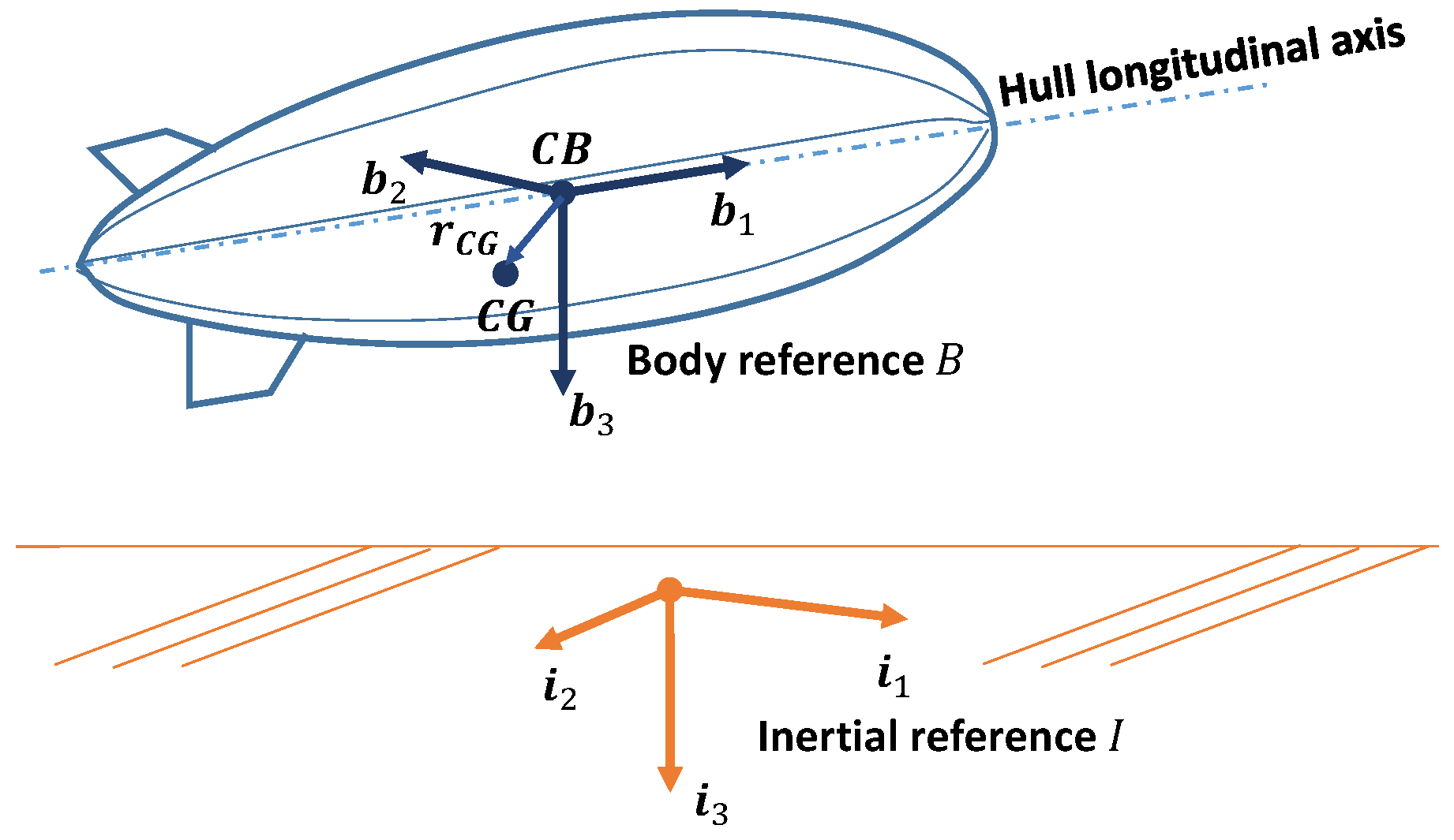
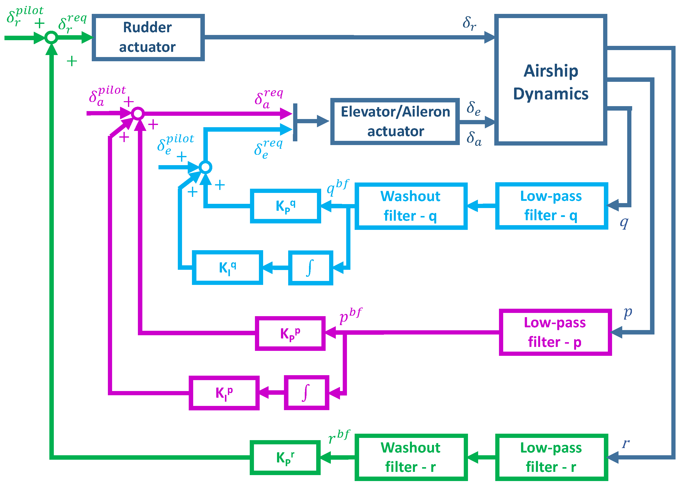
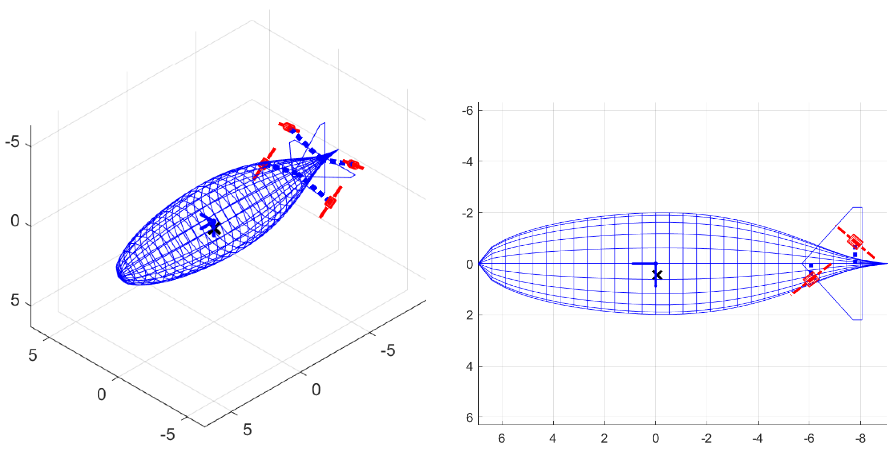
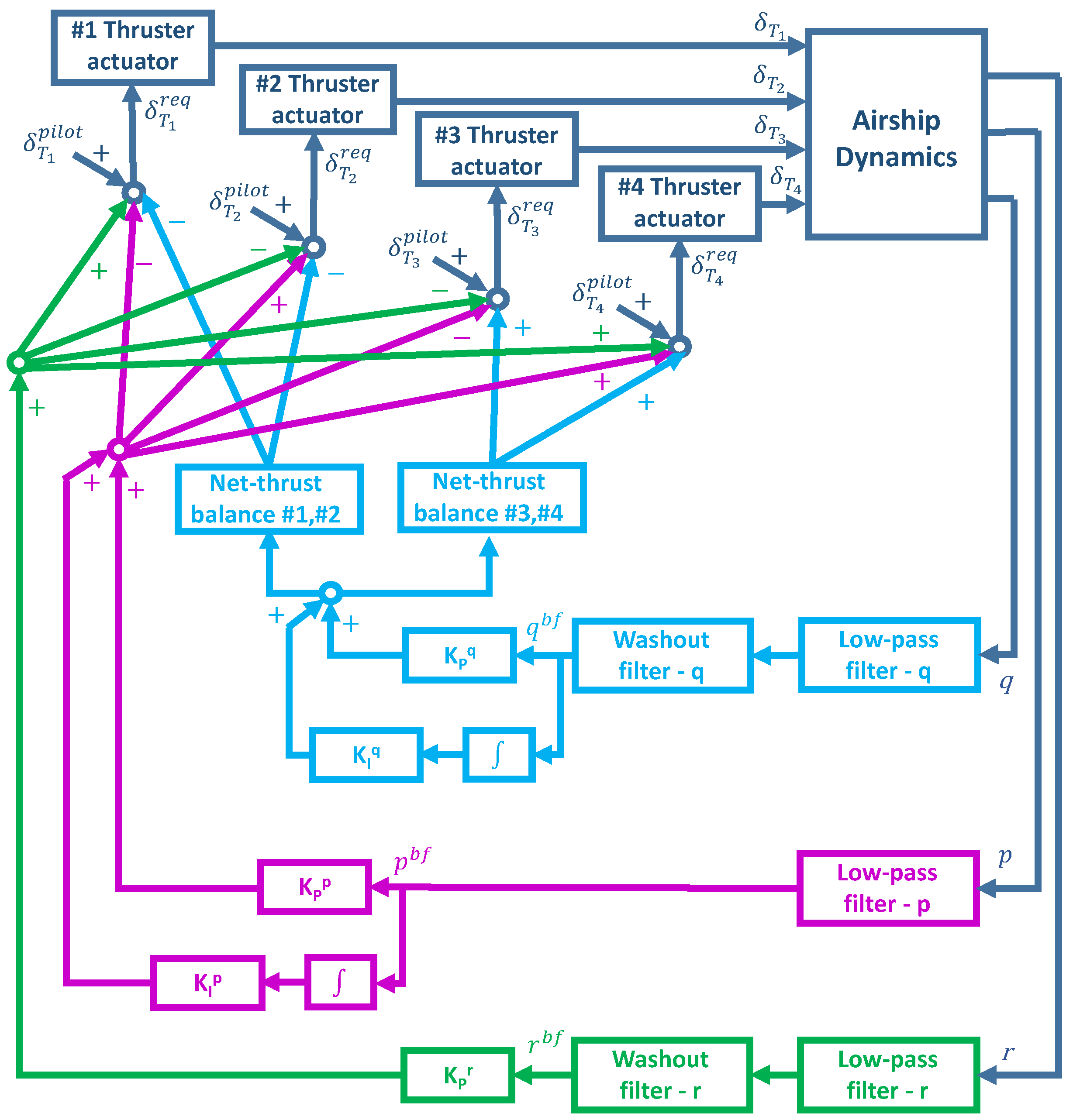
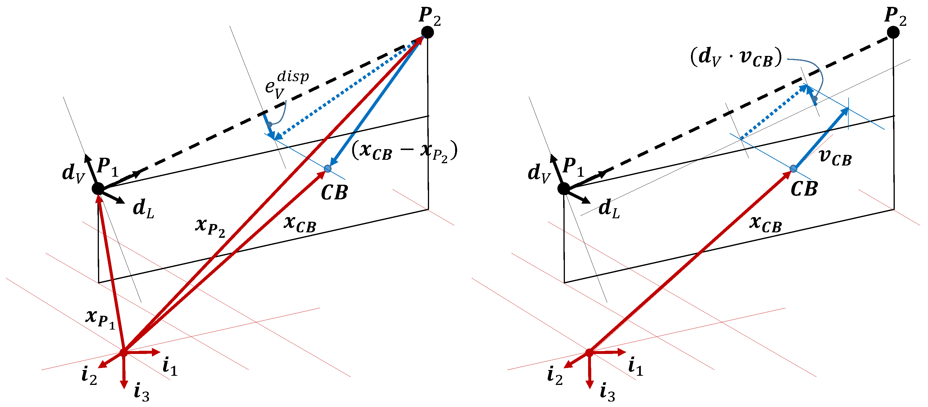
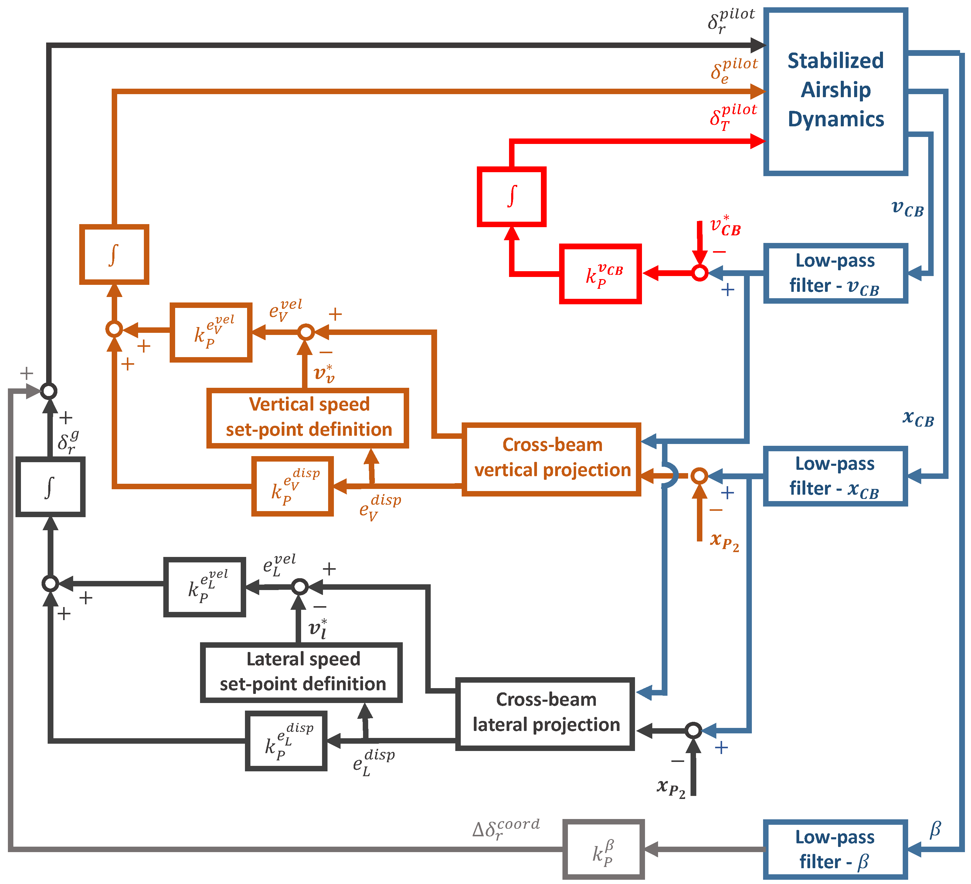
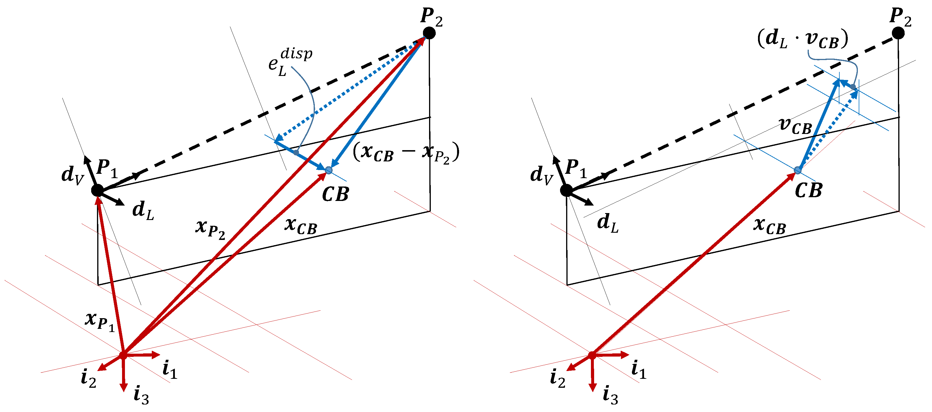
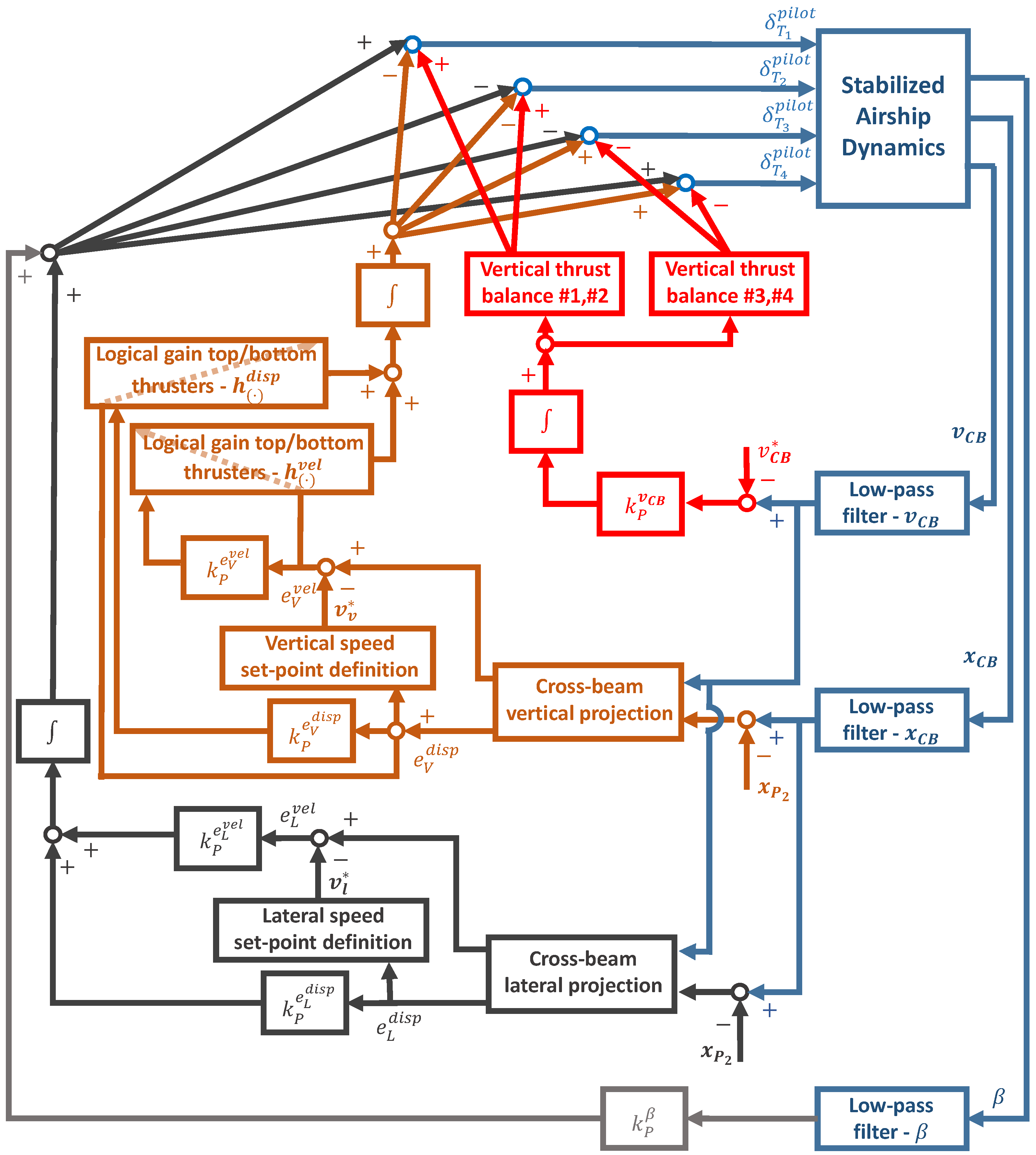
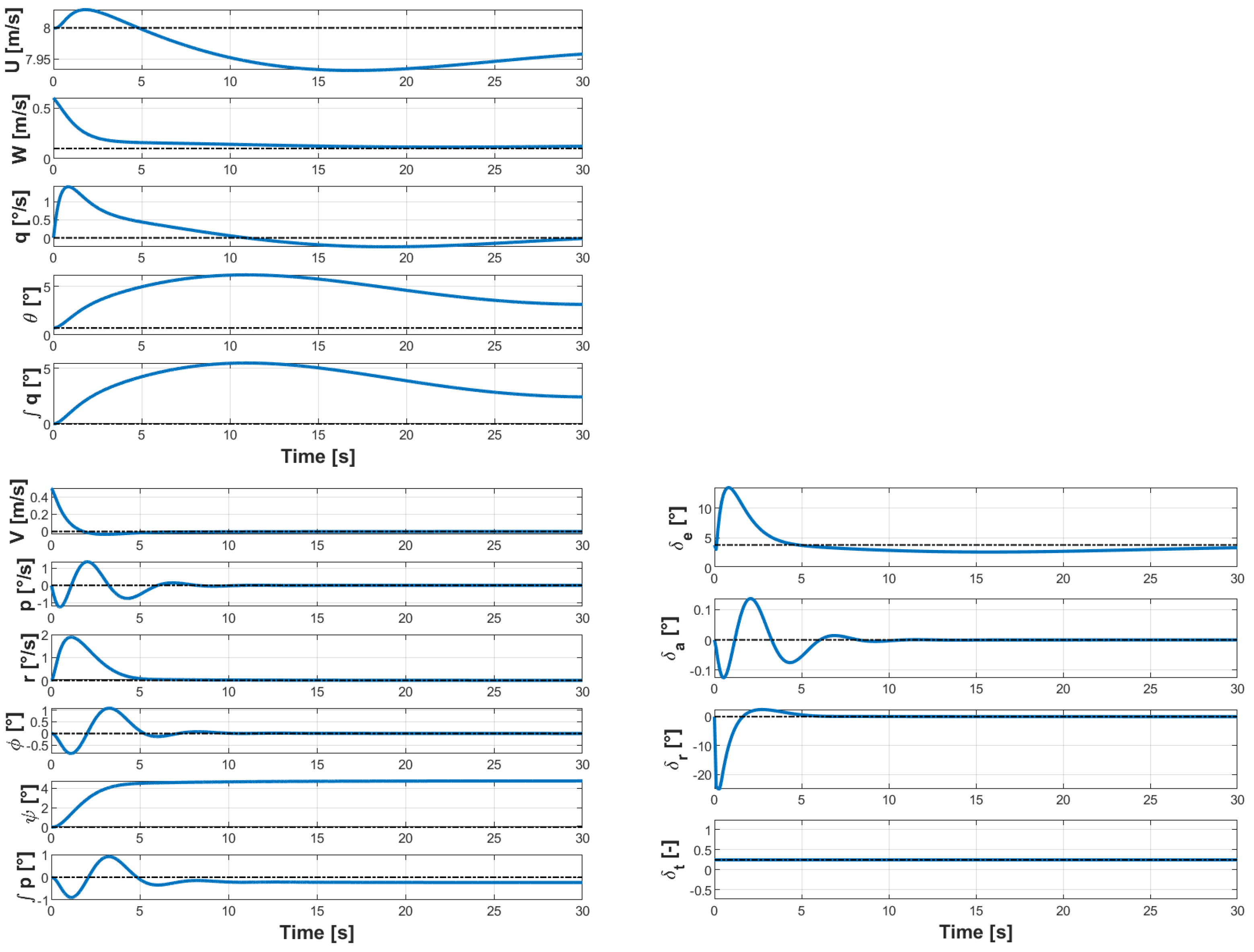
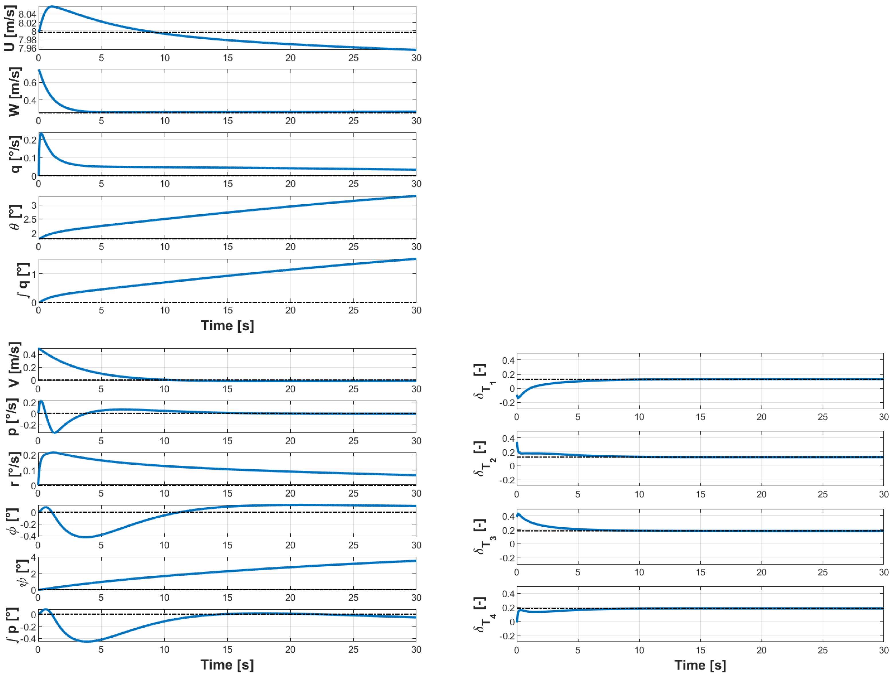
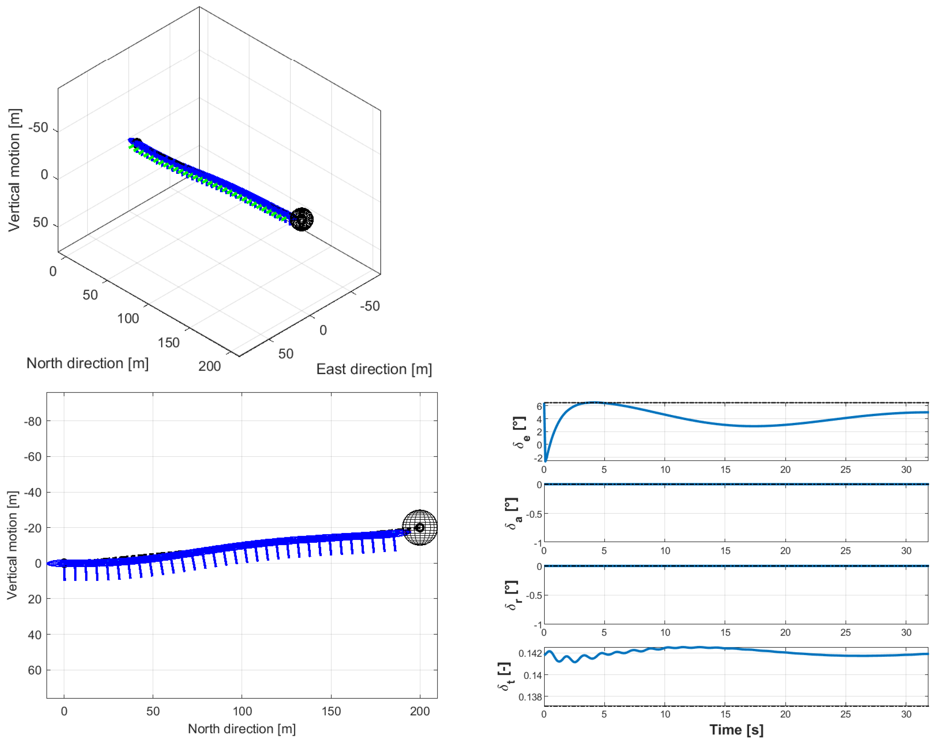
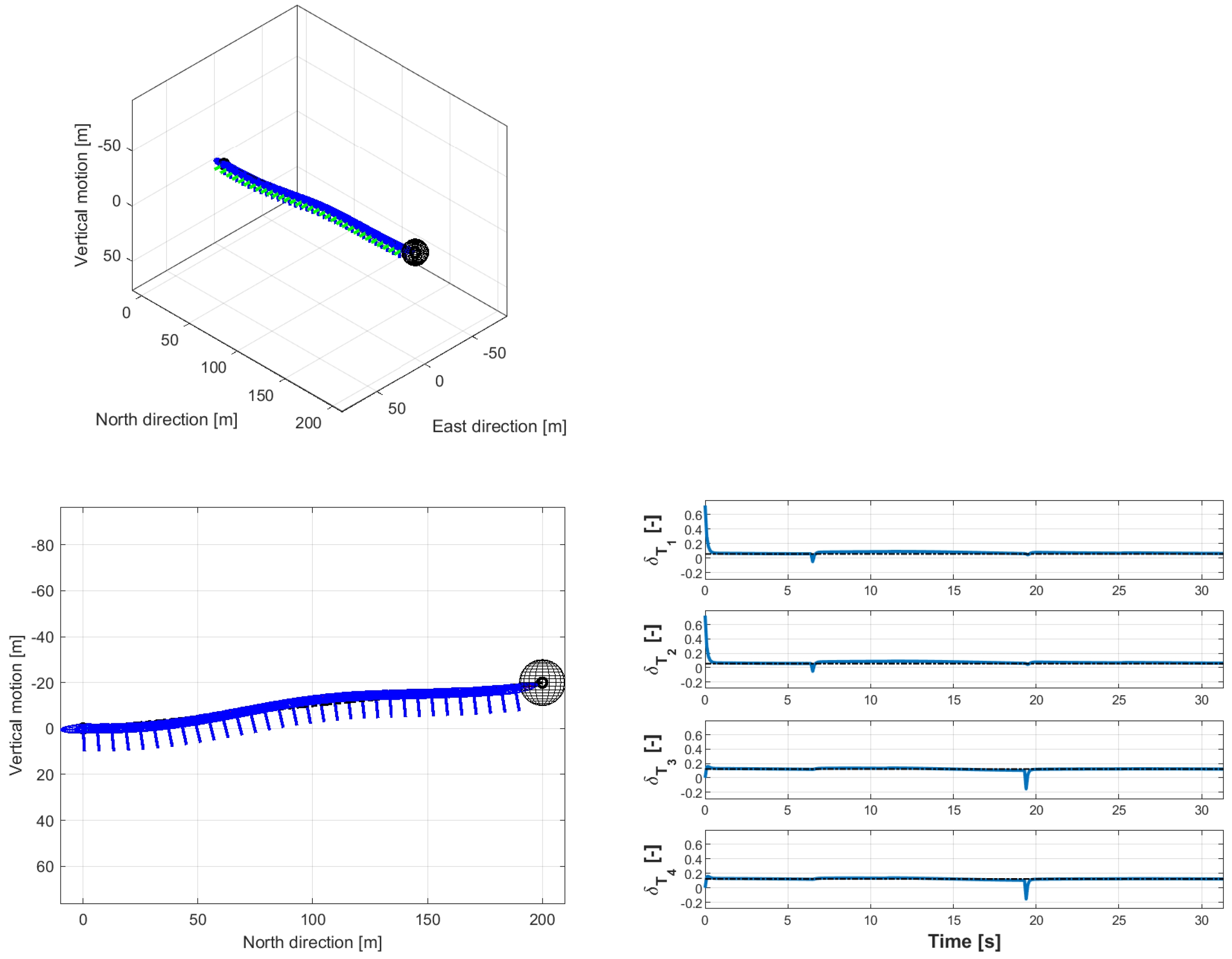
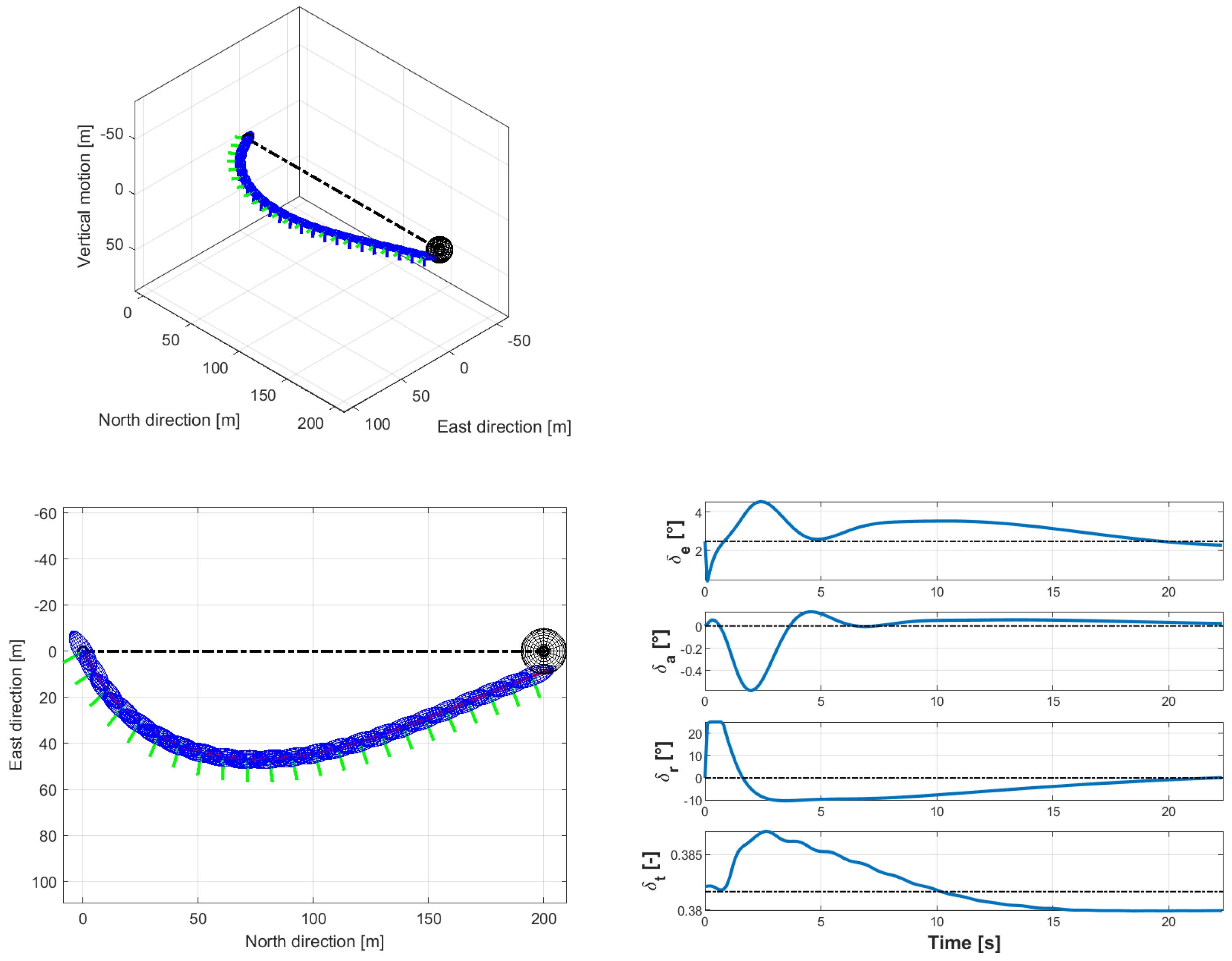
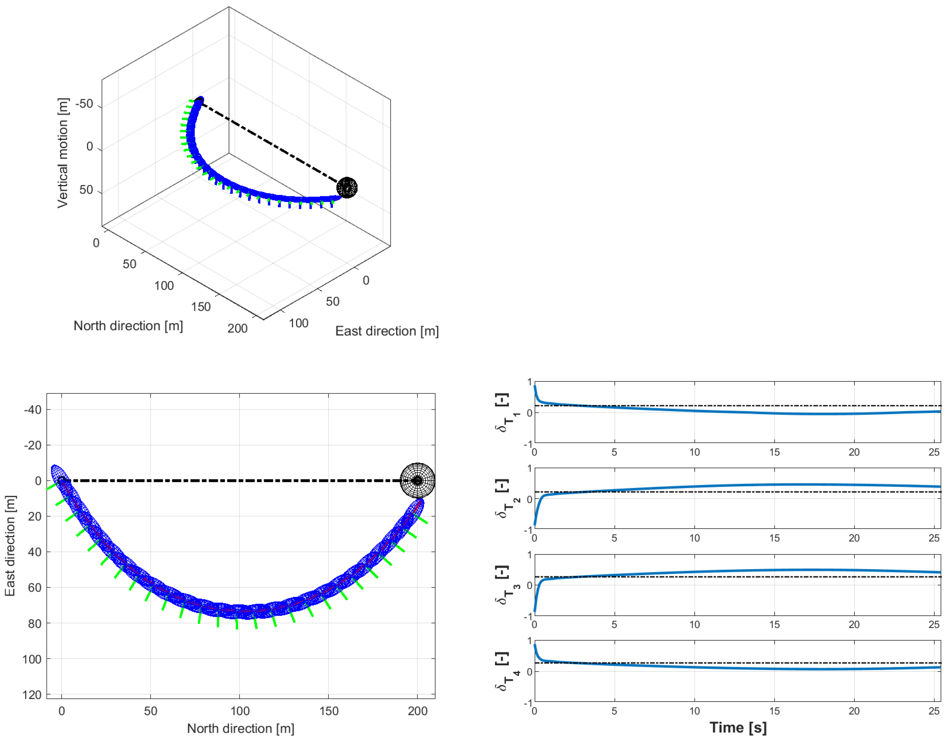
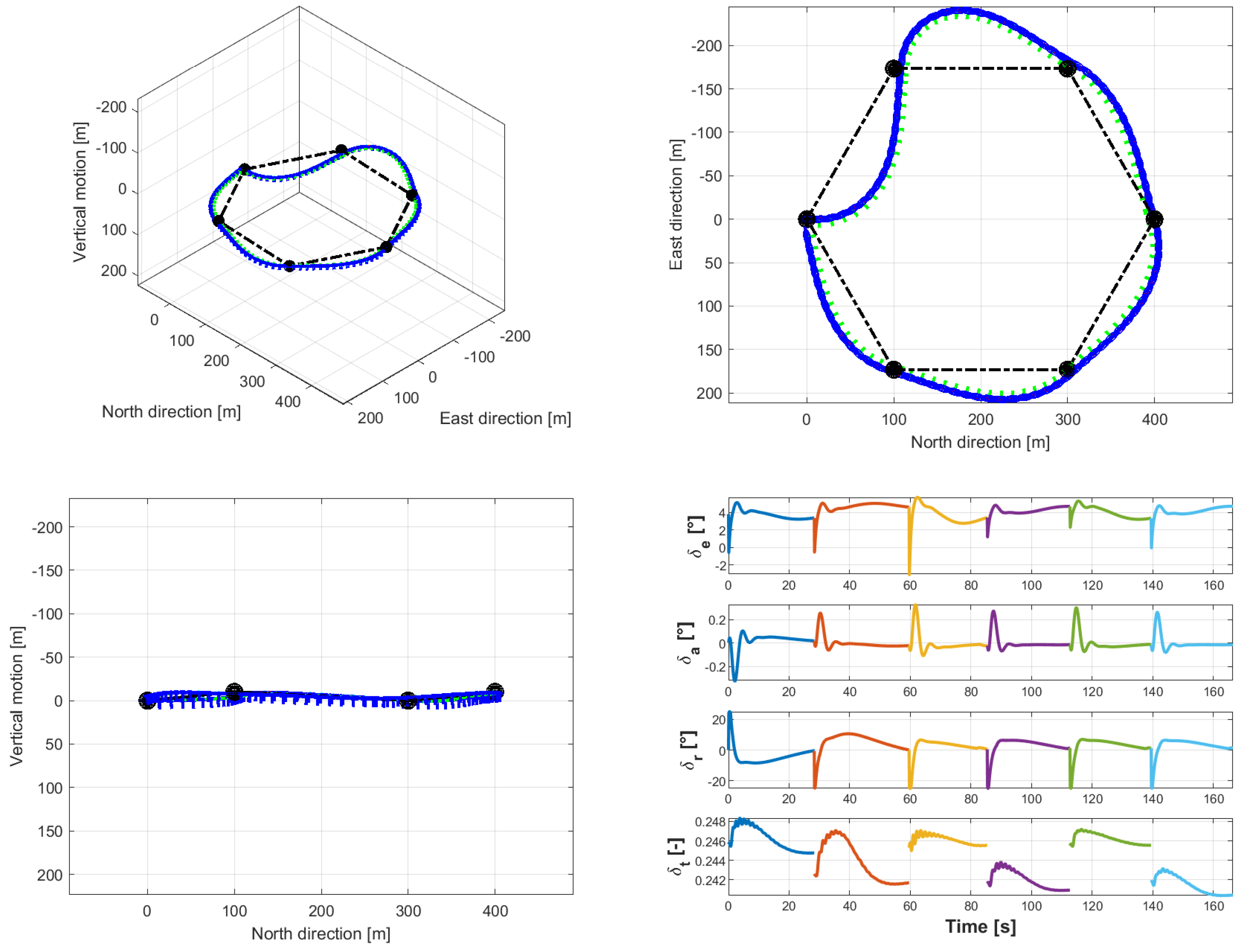
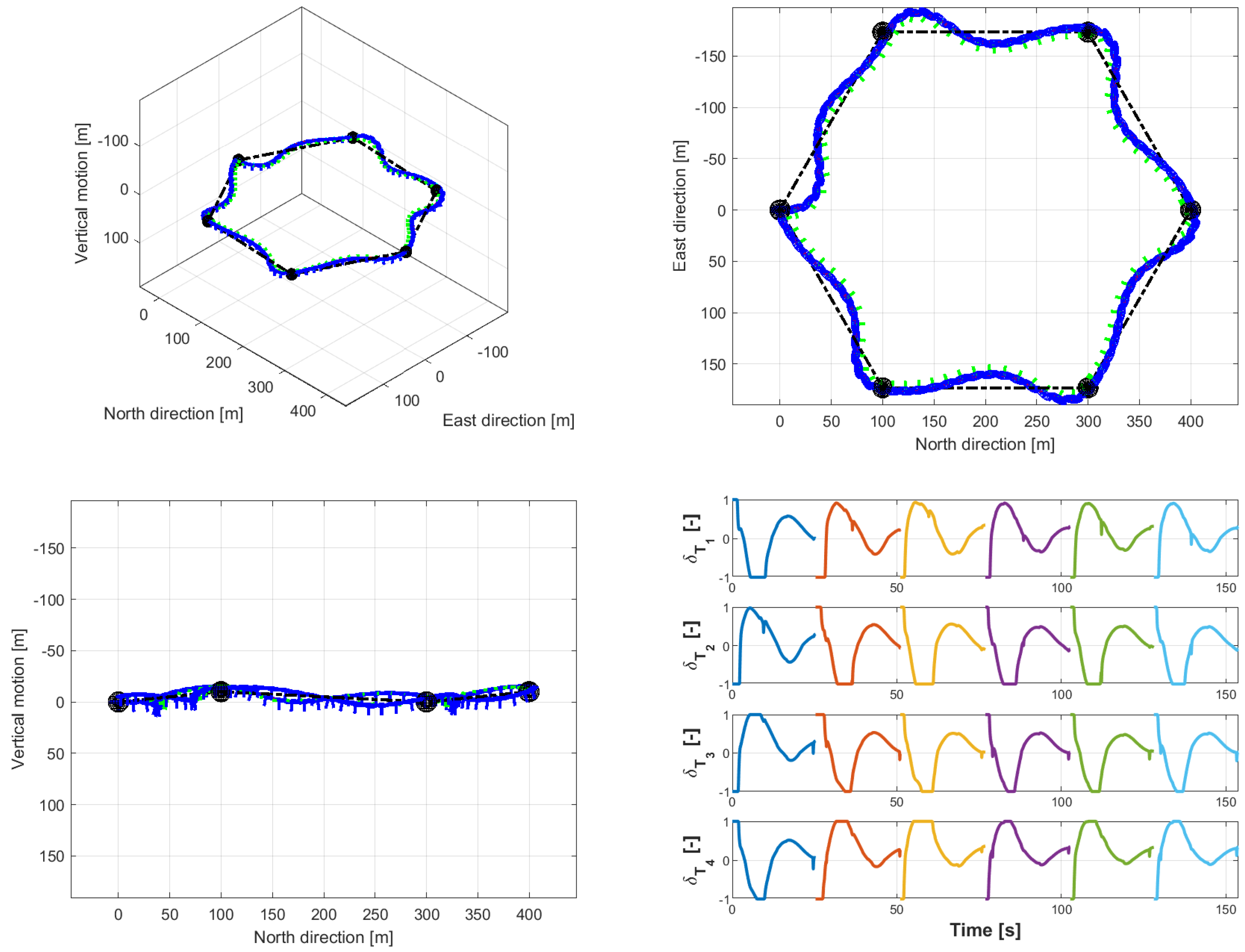
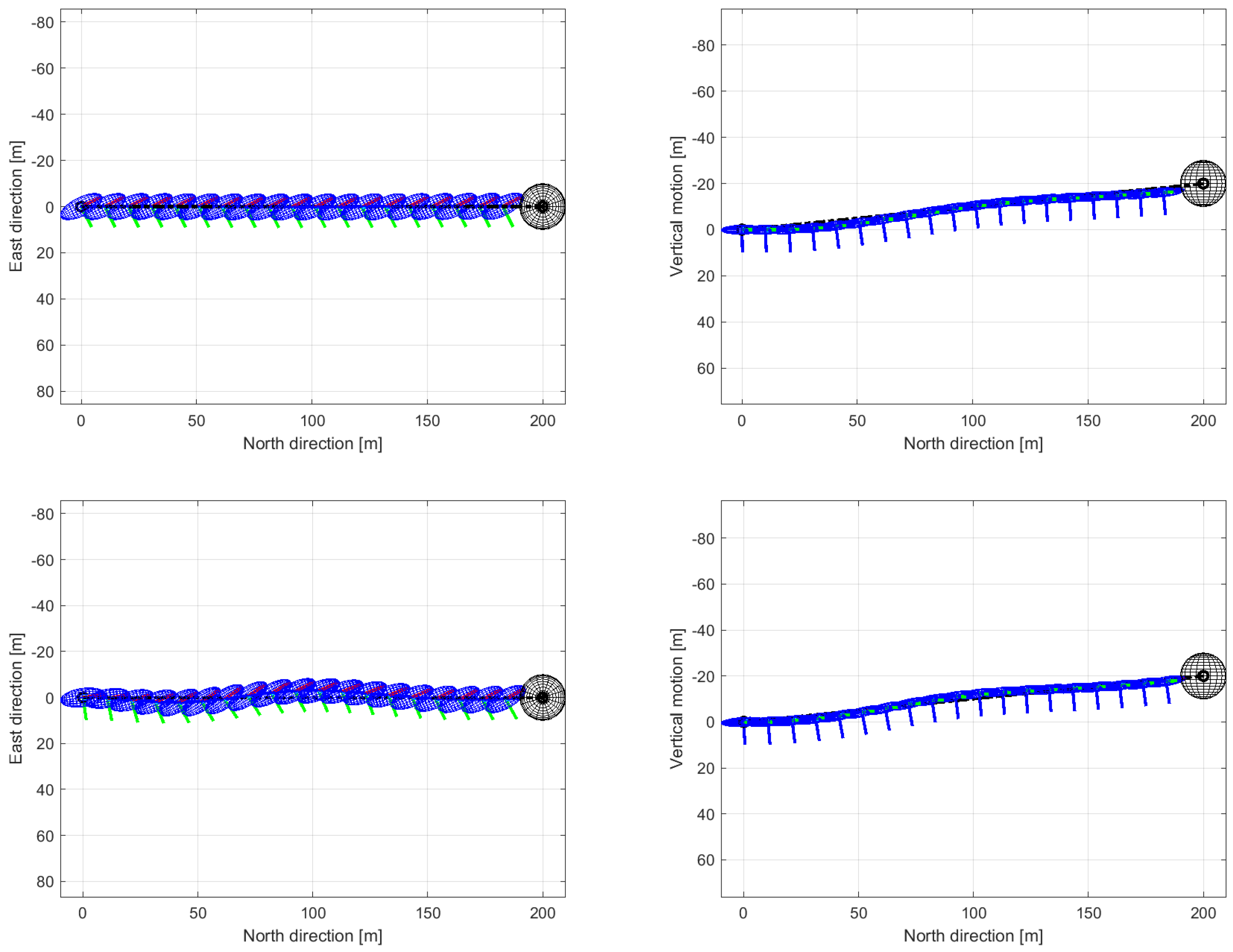
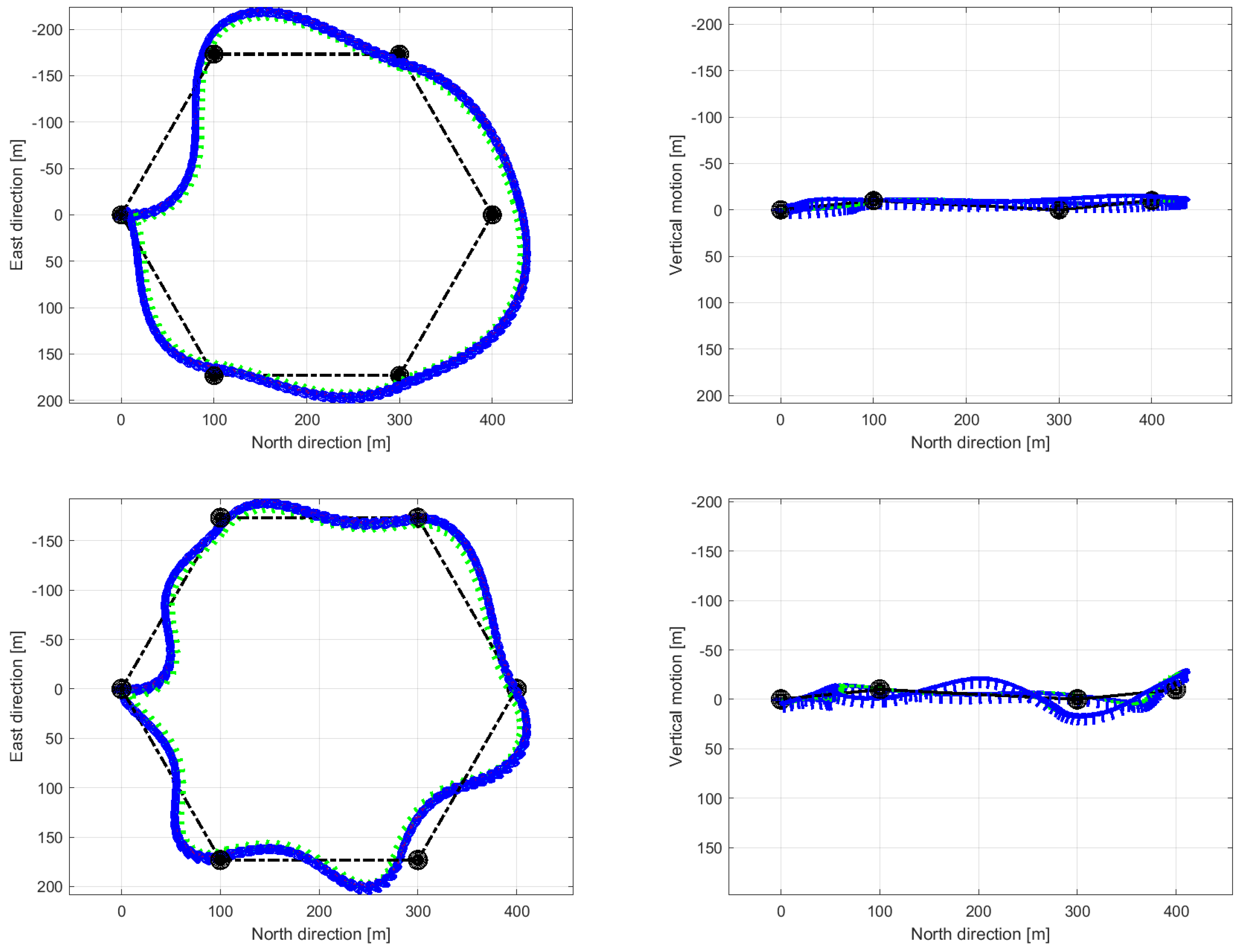
Table 1.
Reference data for the considered airship test beds.
| Parameter | Baseline Airship | 4-Thrusters Airship Concept |
|---|---|---|
| Mass (kg) | 134.28 | 137.28 |
| Envelope volume (m) | 107.42 | 107.42 |
| Overall length (m) | 16.0 | 16.0 |
| Hor. disp. from (mm) | 0 | 5.9 |
| Ver. disp. from (mm) | 455.0 | 455.0 |
| Number of thrusters | 1 | 4 |
| Nominal thrust (each unit) (N) | 500 | 250 |
| Aerodynamic control | Rudder, elevons | (no aerodynamic control) |
Disclaimer/Publisher’s Note: The statements, opinions and data contained in all publications are solely those of the individual author(s) and contributor(s) and not of MDPI and/or the editor(s). MDPI and/or the editor(s) disclaim responsibility for any injury to people or property resulting from any ideas, methods, instructions or products referred to in the content. |
© 2023 by the authors. Licensee MDPI, Basel, Switzerland. This article is an open access article distributed under the terms and conditions of the Creative Commons Attribution (CC BY) license (https://creativecommons.org/licenses/by/4.0/).
Share and Cite
MDPI and ACS Style
Riboldi, C.E.D.; Rolando, A. Thrust-Based Stabilization and Guidance for Airships without Thrust-Vectoring. Aerospace 2023, 10, 344. https://doi.org/10.3390/aerospace10040344
AMA Style
Riboldi CED, Rolando A. Thrust-Based Stabilization and Guidance for Airships without Thrust-Vectoring. Aerospace. 2023; 10(4):344. https://doi.org/10.3390/aerospace10040344
Chicago/Turabian StyleRiboldi, Carlo E.D., and Alberto Rolando. 2023. "Thrust-Based Stabilization and Guidance for Airships without Thrust-Vectoring" Aerospace 10, no. 4: 344. https://doi.org/10.3390/aerospace10040344
Note that from the first issue of 2016, this journal uses article numbers instead of page numbers. See further details here.