Article

Effect of Working Current on C12A7 Hollow Cathode

1
School of Energy and Power Engineering, University of Shanghai for Science and Technology, Shanghai 200093, China
2
School of Mechanical Engineering, Shanghai Jiao Tong University, Shanghai 200240, China
*
Author to whom correspondence should be addressed.
Aerospace 2023, 10(4), 339; https://doi.org/10.3390/aerospace10040339
Submission received: 26 February 2023 / Revised: 23 March 2023 / Accepted: 26 March 2023 / Published: 29 March 2023
(This article belongs to the Special Issue Advanced Small Satellite Technology)

Abstract

:
The C12A7 hollow cathode is expected to usher in a new generation of hollow cathodes because of its low work function and chemical stability. In order to reduce the emission melting and degradation caused by the overheating of this new cathode, different working currents of the C12A7 hollow cathode were studied in this work. The working currents ranged from 1 A to 20 A. The results show that the C12A7 hollow cathode works well under the condition of a low current, but it is unstable under high current condition. A simulation with the COMSOL internal working environment showed that enlarging the cathode orifice size is beneficial to reduce the risk of overheating of the electride emitter. The C12A7 hollow cathode shows a voltage transition phenomenon under a high operating current. The plasma plume state at the cathode outlet gradually changes from bright violet to dark yellow. The emitter also melts at high temperatures under high-current conditions. Its short lifetime makes the C12A7 hollow cathode difficult to apply in practical application scenarios under high-current conditions.

1. Introduction

Commercial spaceflight development in the last decade has ignited great interest in space exploration. The electric propulsion system, with its advantages of high specific impulse, long life, and adjustable thrust, has been applied increasingly widely in the field of aerospace propulsion [1,2]. Hollow cathodes, as an indispensable key component in mainstream thrusters [3], are constantly developing with electric propulsion technology and microsatellites. Currently, hollow cathodes must provide a wide range of discharge power in a variety of conditions, from low-power Hall thrusters with a sub-kilowatt range to large EP applications with over 100 kilowatts [4]. Therefore, it is vital to develop a new type of hollow cathode technology to make the cathode structure more compact, propellant more efficient and lower power consumption in order to make the C12A7 cathode more widely recognized.
L.P. Rand et al. first used C12A7 electride in a hollow cathode test in 2011. The experimental results were significant. Despite the irregular shape of the emitter, the cathode still discharged for several minutes, with the highest discharge current reaching 3.6 A [5]. In 2016, Drobny et al. [6] successfully processed a hollow cylindrical C12A7 emitter and filled it with a stainless steel cathode. The discharge current ranged from 0.2 A to 5 A, and the voltage of the keeper varied greatly from 50 V to 260 V. McDonald and Caruso [7] used copper as a cathode tube in 2017. The cathode worked for several hours under low-current conditions, ranging from 30 mA to 150 mA. After the experiment, it was found that the emitter degraded to a certain extent after discharge, and the cylindrical emitter was also decomposed and broken. In addition, the copper cathode top and wrapped copper foil also had obvious traces of melting, indicating that the actual working temperature of the hollow cathode of C12A7 may be higher than the melting point of copper material. In 2019, Drobny and Tajmar et al. [8] designed a copper saucer-type cathode that activates without heat. The shape of the emitter was a disc, which greatly reduced the difficulty of processing the emitter. The authors believed that the cylindrical emitter was conducive to reducing the temperature gradient of the emitter, and a large number of copper structures were used in the cathode body to reduce the temperature of the emitter further. The stability of the improved C12A7 hollow cathode was greatly improved; the maximum working time reached 350 h, and the maximum current reached 5 A. In 2021, Drobny et al. [9] carried out a long-lifetime experiment on an improved disc-type C12A7 hollow cathode, which worked continuously for 950 h under the 2 A standard discharge condition, which is the longest working time of a C12A7 hollow cathode at present. In 2022, Watzig [10] improved the thermal and mechanical properties of the C12A7 electride by adding Mo metal, improving the performance of the material. Toledo [11] compared the cathode properties of C12A7: e- and Lab6 in different structures and operations. The results showed that C12A7: e- has a distinct advantage in Ar and Xe; above all, greater stability of the anode current was observed with lower mass flows and power cathodes. Hua Zhiwei [12] conducted a microscopic analysis on the surface of C12A7 electride, and the results showed that overheating melts and decomposes the surface layer of C12A7.
As a new hollow cathode technology, the C12A7 hollow cathode is still in the early stages of research and development. The problems of overheating and melting under different working current conditions are reported. In order to reduce the influence of the emitter’s overheating on the lifetime of the cathode, the working current of the C12A7 hollow cathode was studied in this paper. The temperature of the emitter was directly measured by an infrared thermometer to explore the safe working current of the C12A7 hollow cathode. The modeling and simulation of the C12A7 hollow cathode under a low current were carried out by using COMSOL. In addition, the consequences of the C12A7 hollow cathode exceeding the safe current condition were further investigated experimentally. The working current that was used covered 1 A to 20 A, and it was further determined whether the material had the potential to work under high-current conditions.

2. Experimental and Model Setup

2.1. C12A7 Hollow Cathode

In this paper, the C12A7 emitter was machined by special tools into a hollow cylinder with an inner diameter of 2 mm, an outer diameter of 5 mm, and a length of 10 mm. The C12A7 hollow cathode in this paper improves on the hollow cathode, which was successfully tested and ignited at Shanghai Jiao Tong University [13]. The old cathode working current was 1 A–4 A for a total of 10 h, after which the emitter degraded. On this basis, the C12A7 hollow cathode was improved for high-current working conditions, and the cathode aperture was expanded from 1 mm to 3 mm. The C12A7 emitter and the C12A7 hollow cathode are shown in Figure 1.

2.2. Testing Facility

In this paper, the hollow cathode experiment was carried out in a vacuum chamber with a size of Φ 400 mm × 1200 mm, equipped with two molecular pumps with an effective pumping speed of 2000 L/s and a limit pressure of 2.0 × 10⁻⁵ Pa. The hollow cathode power supply system—an IT6516 DC power supply (750 V/15 A/1800 W) and an IT6515 DC power supply (500 V/20 A/1800 W)—were provided by the Idex DC power series. The vacuum chamber and power supply system are shown in Figure 2. The voltage and current parameters were recorded by the Oscilloscope Tektronix MDO3054 (Tektronix, Beaverton, OR, USA) Mixed Domain Oscilloscope (500 MHz, 2.5 GS/s) and the oscillograph, HIOKI MR6000 (HIOKI, Nagano, Japan). The non-contact measurement and monitoring of the cathode’s temperature were carried out with a Shiao infrared thermometer (600–1400 °C). The uncertainty of the whole measurement system comprises the following aspects: the accuracy of the power system is 0.05%/0.2%, the accuracy of the probe is 1%/2%, the resolution of the oscilloscope is 8-bit, and the accuracy of the system is 1.5%. The system accuracy of the two-color thermometer is 1%, and the corresponding time is 10 ms.

2.3. Experimental Procedure

The C12A7 hollow cathode was ignited by the heaterless ignition method; that is, when the external heater is not working, the high voltage between the keeper and the cathode is used to break down the working medium gas and generate discharge plasma bombardment of the emitter, which is heated to the ignition temperature and then activated. The electrical schematic of the heaterless C12A7 hollow cathode test setup is shown in Figure 3. The specific experimental steps are as follows:
(1) The electride emitter was cleaned with ethanol, removing the grease and dust on the surface, and placed into the hollow cathode. A stainless steel air pipe was installed, and the air pipe and bulkhead were insulated with Teflon hose or porcelain seal alloy. In order to prevent the interference of unexpected factors, we heated the hollow cathode to remove impurities. After the background pressure of the vacuum chamber was reduced to 10−3 Pa, the heater was activated at 1.5 A and 2.4 V for half an hour, 2.5 A and 3.9 V for half an hour, and 3.5 A and 6.1 V for half an hour to remove different impurities inside the cathode at different stages.
(2) The C12A7 hollow cathode was injected with 2 sccm Xe for 1 min to exclude the impurities that may exist in the pipeline. Then, the ignition parameters of the keeper were set to Vk = 500 V, Ik = 2 A, and the xenon flow rate to 18 sccm.
(3) The mass flow controller was turned on after the ignition power was set up, and a violent gas breakdown occurred immediately after the working medium gas entered the cathode.
(4) A large number of hot electrons escaped from the surface of the emitter, and a stable electronic loop was established between the keeper and the cathode. The current was then stabilized at the set value, the voltage was maintained at about 20 V, the color of the cathode plume became bright violet, and the C12A7 hollow cathode was successfully activated without hot particles.

2.4. Model Construction

We used COMSOL to simulate the internal working environment of the cathode. Since the flow field area inside the hollow cathode is rotationally symmetric, a two-dimensional axisymmetric model was adopted to simplify the corresponding model. The inner diameter of the cathode tube was 7 mm, the inner diameter of the emission body was 2 mm, the length was 10 mm, the orifice size of the cathode orifice was 3 mm, and the width of the plume area was 8 mm. The geometry of the simulation is shown in Figure 4.
In finite element analysis, the mesh size greatly influences the convergence of the model, and one of the difficulties in plasma modeling is that the mesh size requires the analytical Bide length. Therefore, the mesh needs to be extremely refined for a small orifice area with high plasma density and also in places where the plasma gradient changes greatly, such as the boundary of the emitter. For the cathode tube area and the transition area between the cathode top and the keeper, the mesh needs to be refined. For the solid wall area, a relatively sparse mesh can be used, as shown in Figure 5. The final number of grids divided by this model was 707,960.
Plasma discharge is a drift-diffusion model, and therefore, by solving a pair of drift-diffusion equations describing electron density and electron energy density, the characteristics of electron diffusion and drift along the direction of an electromagnetic field are described [14].
n e t + · Γ e = R e
n ε t + · Γ ε + E · Γ e = R ε
where n e , n ε are the electron density and electron energy density, respectively, and Γ e , Γ ε are the electron flux and electron energy flux, respectively.
Γ e = μ e · E n e D e · n e
Γ ε = μ ε · E n e D ε · n e
where μ is the mobility, D is the diffusion coefficient, and E is the electric field.
The potential distribution of plasma is calculated by the Poisson equation.
· φ = ρ i ε 0 ε r
The charge ρ i is calculated by the number density of the electrons and other charged particles:
ρ i = e m = 1 N Z m n m n e
The mass fraction of each particle of a heavy substance can be obtained by solving the mean diffusion model of mixtures (a modified form of the Maxwell–Stefan equation):
ρ a ω k t + ρ a u · ω k = · ρ a ω k V k + R k
ρ a is the average density of the mixture, ω k is the mass fraction of substance k, u is the fluid velocity, and R k is the reaction rate expression of substance k.
The behavior of plasma is largely determined by plasma chemistry. For Xe, the types of substances considered include electrons, xenon atoms, excited xenon atoms, and xenon ions, where the xenon atoms meet the mass constraint, and the xenon ions meet the electroneutral constraint. Xenon discharge contains a large number of chemical reactions, including ionization, surface reactions, heavy matter reactions, etc. The rate constant of the reaction is calculated by combining the collision cross-section with EEDF [15].
The laminar flow module obtains the plasma pressure distribution inside the cathode by solving the mass conservation equation and momentum equation:
ρ t + · ρ u = 0
ρ u t + ρ u · u = · p I + τ
where ρ is the density, u is the velocity field, p is pressure, I is the characteristic matrix, and τ is the viscous stress tensor [16].
The fluid and solid heat transfer module obtains the temperature field distribution results of the solid part of the cathode by solving the heat conduction equation and the radiation heat dissipation equation. The surface temperature of the emitter is solved by the solid heat transfer module and is used as the boundary condition of heat emission. The surface heat transfer Q of the emitter includes the bombardment heating of xenon ions and electrons, gas heat transfer, and the heat consumed by the thermos-electron emitter. The expression of each parameter is as follows [17]:
Q = Q i + Q e + Q g Q c
where Q i is the heat generated by xenon ion bombardment; Q e is heating by electron bombardment; Q g is gas heat; and Q c is the heat lost by electron thermal emission

2.5. Physical Parameters of C12A7 Electride

The results of the literature on the thermal property test of C12A7 electride materials show that the thermal conductivity of C12A7 electride is low, about 2.3 W/m·K at room temperature and about 1.7 W/m·K at 1000 °C [18]. The C12A7 electride materials used in this paper were prepared by the Beijing University of Technology [19]. Considering the influence of the preparation method and treatment technology on the materials’ properties, it was necessary to actually measure the thermal conductivity of the C12A7 electride used in this paper. The calculation formula for measuring thermal conductivity is as follows:
κ = C p · α · ρ
where ρ is the density, Cp is the specific heat capacity, and α is the thermal diffusion coefficient. The measured density of the C12A7 electride at room temperature was about 2.2257 g/cm3. The measurements of the specific heat capacity and thermal diffusivity of the C12A7 electride at different temperatures are shown in Table 1.
The thermal conductivity coefficients of the C12A7 electride at different temperatures were calculated according to Equation (11), as shown in Table 2. Limited by testing instruments, the maximum thermal conductivity can be measured at about 500 degrees Celsius. Considering the relationship between thermal conductivity and temperature, as well as the results reported in the literature, this paper tentatively determined the thermal conductivity of the C12A7 electride at about 1000 degrees as 2.1 W/m·K.
Since the emitter of C12A7 is a smooth, pure black object, its thermal radiation emissivity coefficient was roughly estimated to be about 0.9. The C12A7 electride density was 2.23 (g/cm3).

2.6. Model Verification

In order to verify the accuracy of the model calculation, the simulated temperature results were compared with the steady-state operating temperature of the C12A7 electride insert that was measured by the infrared double-wave temperature thermometer. Figure 6 shows a schematic diagram of temperature measurement for electride insert. The temperature of the C12A7 electride insert was monitored by the infrared double-wave temperature thermometer from the heating stage. After the infrared double-wave temperature thermometer was activated at the cathode, the infrared signal of the temperature measuring point was submerged by a bright violet plume at the cathode outlet so that the temperature indicator on the instrument disappeared (indicating that it was out of range). As soon as the hollow cathode stopped working, the plume at the cathode outlet disappeared, and the temperature on the meter returned immediately, with almost no delay. The first indicator that appeared on the thermometer after the cathode stopped working was considered the stable operating temperature of the C12A7 hollow cathode insert under the specified operating conditions. It can be seen from the comparison results that the maximum error was less than 5%; therefore, the calculated results can be considered credible. Comparison of measured and calculated values of the insert operating temperature are shown in Table 3.

3. Results and Discussion

Figure 7 records the complete voltammetry curve of the C12A7 hollow cathode from the ignition start to the self-sustaining discharge and current adjustment over a wide range (from 1 A to 20 A). It can be seen that the discharge state of the C12A7 hollow cathode is stable under low-current conditions, and the anode voltage gradually decreases with the increase of the anode current. The first transition of the anode voltage occurred around 380 s. At this time, the current value displayed by the power supply remained unchanged at 12 A, and the anode voltage suddenly increased from more than 10 volts to about 20 volts, and the shock was serious, while the data from the oscillograph show that the current shock was also serious at this time. This voltage transition phenomenon was not a difference between the point mode and the plume mode, it was more like a switch between the two different discharge modes.

3.1. Low Working Current

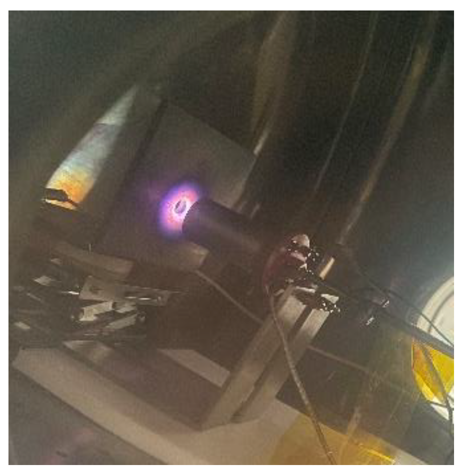
Under the condition that the anode current 2 A was fixed, the outlet of the keeper was a bright violet plume, and the position of the port of the keeper showed an obvious contraction of the bright white spot, as shown in Figure 8. At this time, the anode voltage was also relatively stable, and the voltage fluctuation did not exceed 2 V.
The orifice size is the most critical dimension in the design of a hollow cathode. Compared with other structural dimensions, the cathode orifice size directly affects the working range of current, cathode working temperature, and discharge voltage. In this paper, two types of cathodes with different orifice sizes were calculated. The orificed emitter configuration refers to the structure type, where the size of the cathode orifice is small, and the emitter is completely wrapped in the cathode tube [20,21]. In traditional low-current Bao-W and Lab6 cathode designs, the orifice size of the cathode is usually less than 1 mm. The main purpose is to maintain a high plasma density in the cathode orifice and emitter areas to prevent the cathode from working at too low a temperature. For the C12A7 electride, this material, with a low work function, is suitable for working under low-current conditions, while too small a cathode orifice may cause the emission temperature of the C12A7 electride to be too high. The open-end emitter orifice keeper configuration was first designed by Aston et al. [
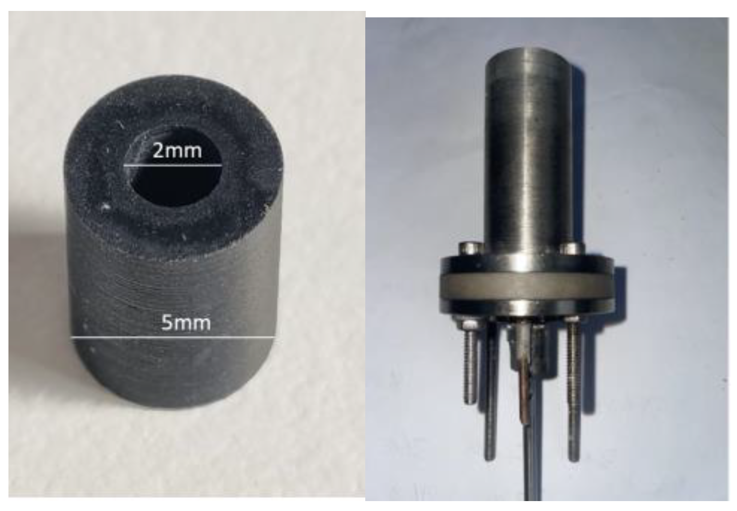
22]. This type of structure is characterized by a large cathode orifice size or the absence of a cathode top, which causes the emitter to be exposed to the plume region. It is often used in a hollow cathode without a high current. The discharge stability of a hollow cathode under a high discharge current can be improved effectively by increasing the orifice size of the cathode orifice and reducing the working voltage. In this paper, the size of the cathode orifice in the C12A7 hollow cathode was 3 mm. In addition to reducing the working temperature under high currents, exposing the emitter can also realize the direct measurement of the working temperature of the emitter of the C12A7 electride.
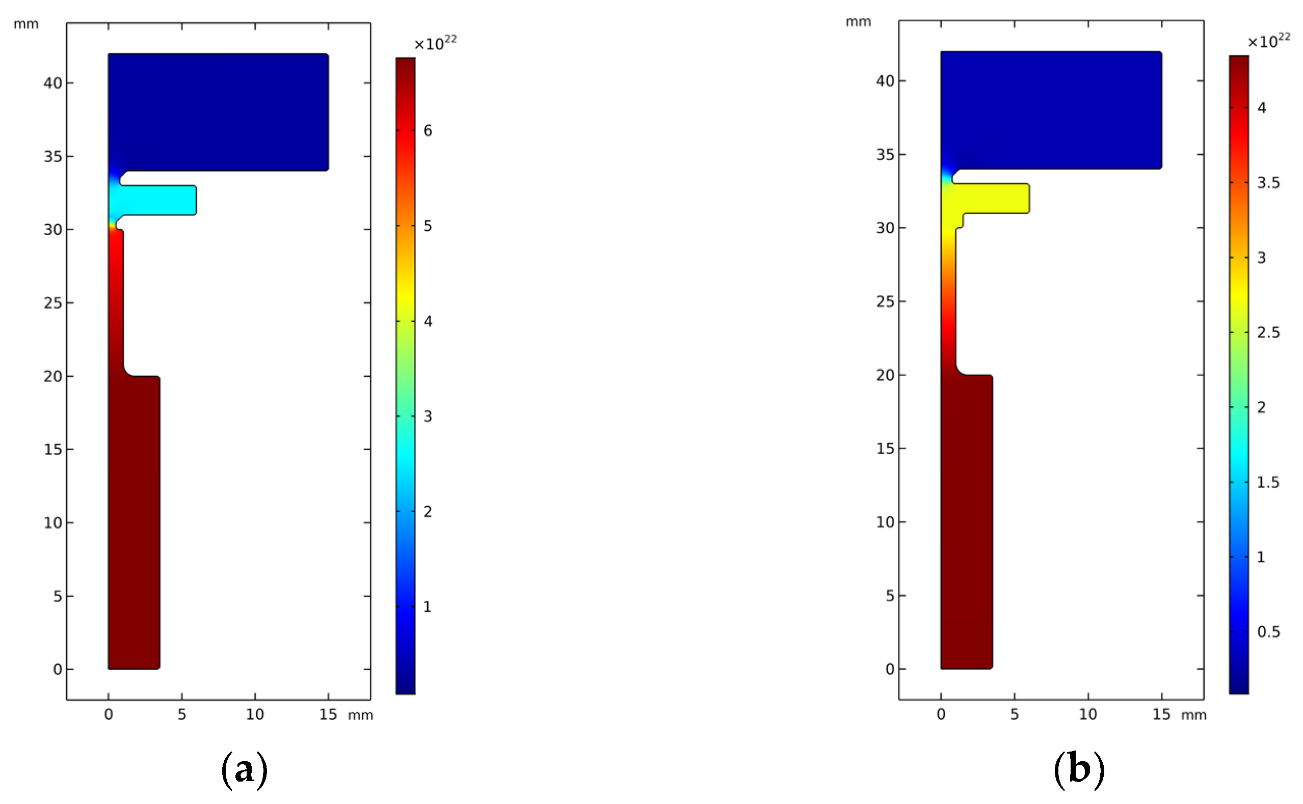
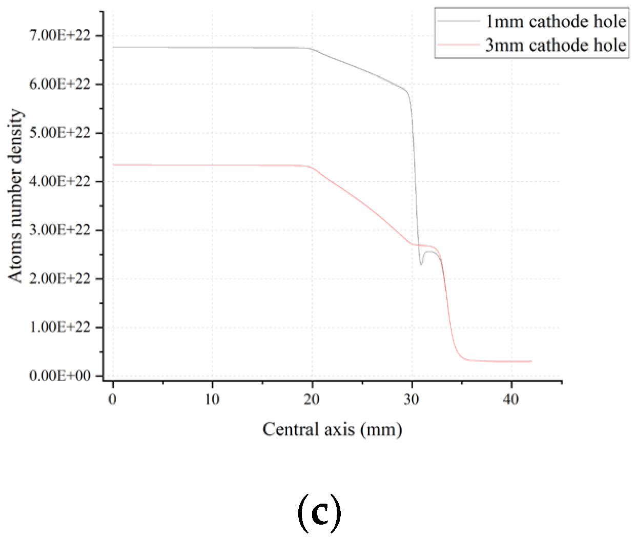
The atomic number density reflects the amount of gas in the cathode and affects the frequency of ionization collision. Figure 9 shows the simulation distribution results of the atom number density of the small-orifice cathode (1 mm) and the open-orifice hollow cathode (3 mm) under the state of steady discharge, where the anode current is 2 A and the xenon flow rate is 10 sccm. As can be seen from the density distribution of the xenon atoms inside and outside the cathode, the density of the xenon atoms inside and outside the cathode differed greatly. For the cathode with small pores, the density of the xenon atoms inside the cathode reached up to 6.7 × 10²²/m3 due to the flow limiting and pressure boosting effect of the cathode orifices, slowly dropping to 5.9 × 10²²/m3 in the emitter region. Then, it dropped to 2.5 × 10²²/m3 at the cathode orifice. Compared with the small-orifice cathode, the inner atomic number density of the open-orifice hollow cathode obviously decreased, and the maximum atomic number density was about 4.3 × 10²²/m3. However, the atomic number density at the cathode outlet increased slightly, about 2.7 × 10²²/m3. The enlargement of the cathode orifice size reduced the throttling effect of the cathode orifice, resulting in decreased pressure inside the cathode and increased pressure at the outlet.
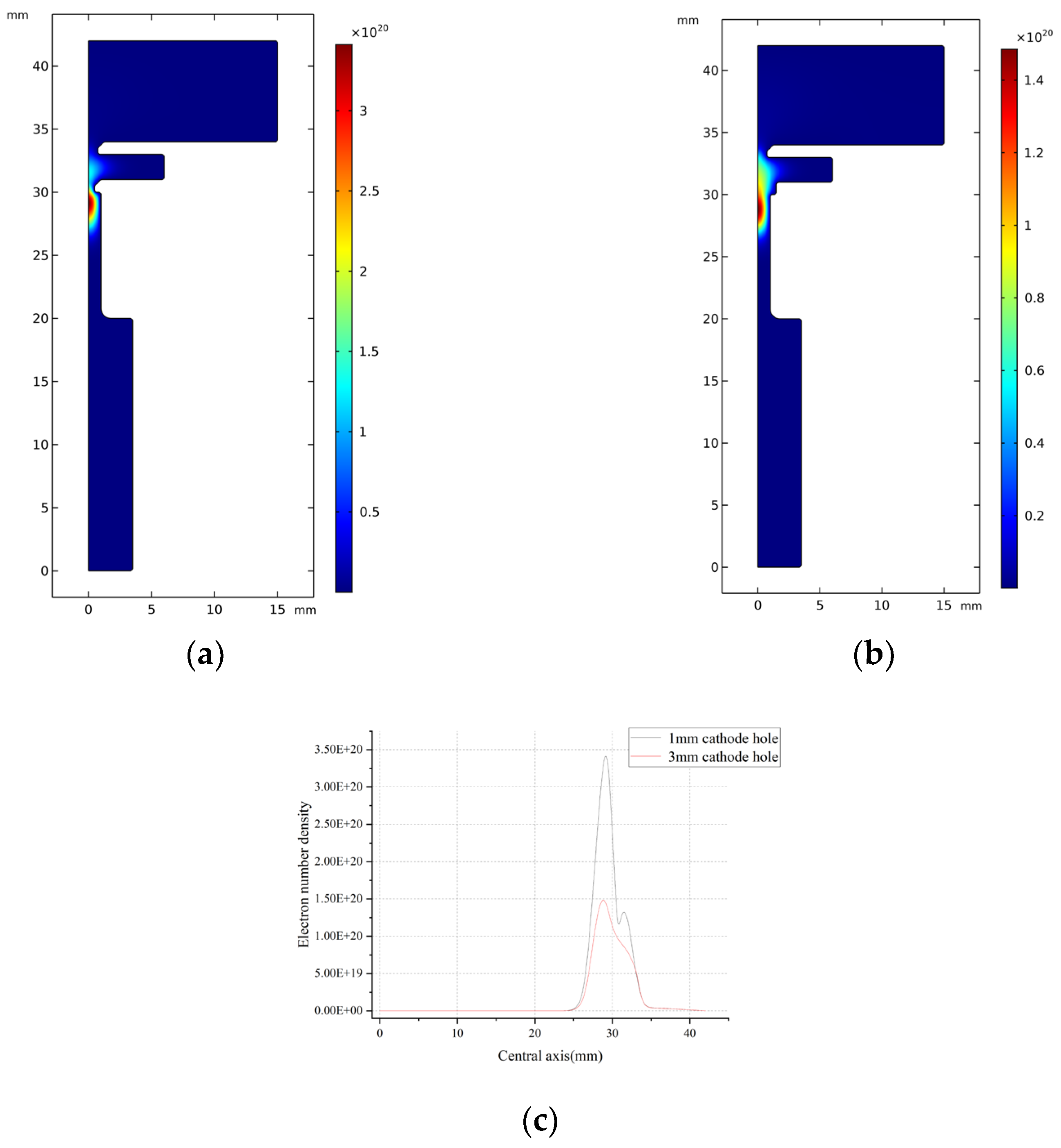
As can be seen from the electron number density simulation distribution cloud, Figure 10 shows that the area near the orifice was the area with the highest electron number density inside the hollow cathode, indicating that this area is the location where the particle collision reaction was the most intense. The number density of electrons in the cathode reached a maximum value of about 3.4 × 10²⁰/m3 near the cathode orifice, and there was a second small wave peak of about 1.2 × 10²⁰/m3 at the cathode orifice outlet. For the open-orifice hollow cathode, the decrease in the neutral atom density inside the cathode led to a decrease in particle collision frequency and plasma density. However, it was also more evenly distributed. Therefore, the region with the highest electron number density in the cathode is located near the emitter and extends outwards, with a maximum value of about 1.45 × 10²⁰/m3.
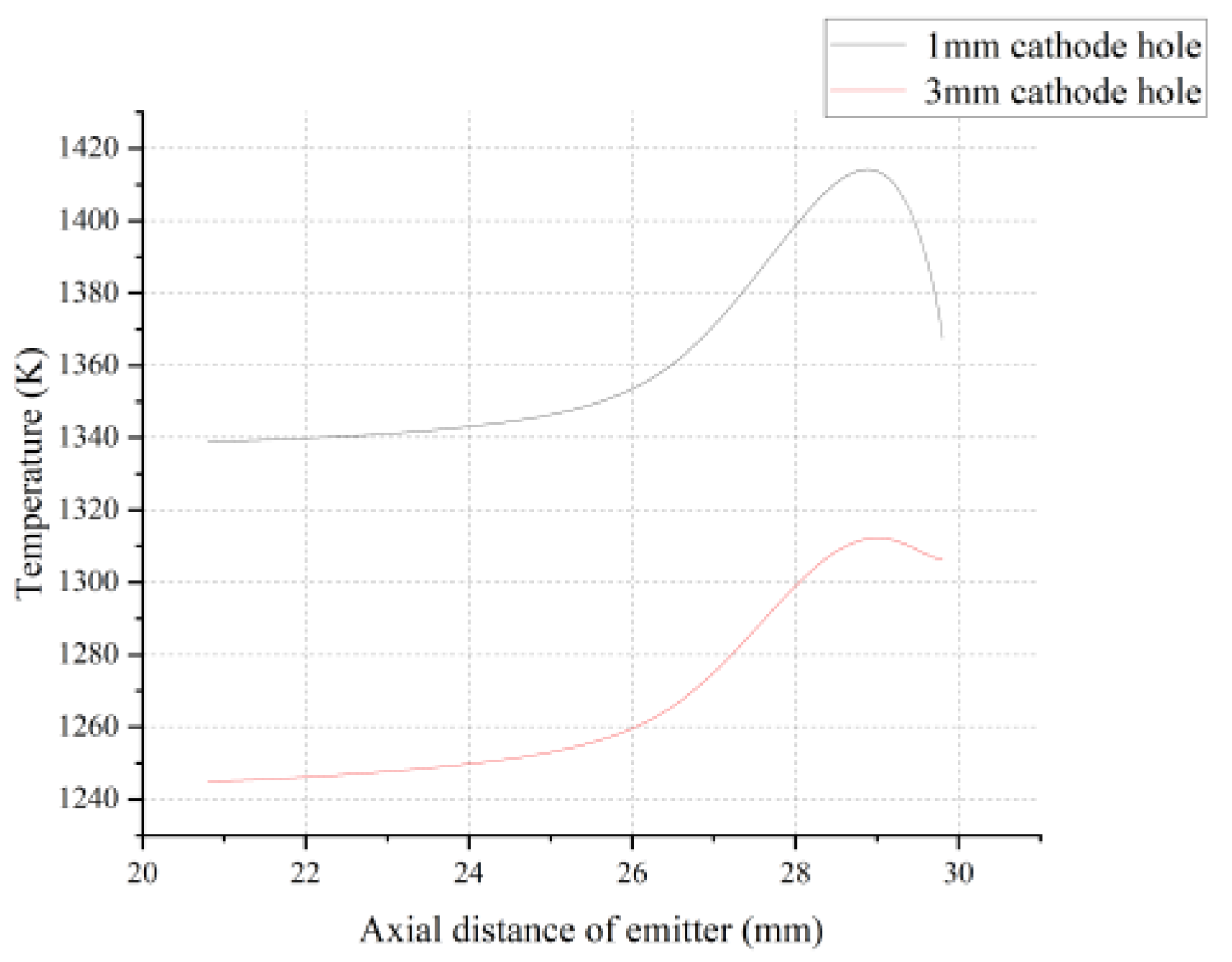
Figure 11 shows the temperature distribution of the C12A7 electride along the axial direction. It can be seen that the downstream of the emitter near the top of the cathode was the part with the highest temperature of the whole cathode. The open-orifice hollow cathode (3 mm) was 50 K lower than the small-orifice cathode (1 mm). This shows that the enlargement of the cathode orifice size is beneficial to reduce the risk of overheating of the C12A7 electride. The smaller orifice size increased the pressure on the cathode and shifted the peak plasma density closer to the cathode pore, which increased the power deposited on the surface of the plasma bombardment in the region, causing the emitter temperature to rise. With the increase of the discharge current, both the emitter temperature and the overall cathode temperature of C12A7 rose. When the working current was 4 A, the maximum temperature of the C12A7 electride reached 1520 K, which is close to the maximum allowable working temperature of 1548 K for the electron emissions of C12A7. The element analysis in the literature [12] shows that, at more than 1548 K, the C12A7 electride will decompose into C3A and CA, which is detrimental to the hollow cathode’s ability to work stably for a long time. Therefore, the C12A7 hollow cathode is reasonable under low-current working conditions, and its maximum safe working current is 4 A. If it is necessary to increase the safe working current, it is necessary to use copper material with higher thermal conductivity and optimize the heat dissipation structure for the design of a C12A7 hollow cathode.
In addition to the increased the plasma bombardment heat flow, it is also believed that the ohmic heat, caused by high resistance, is related to the high temperature of the emitter. It is difficult to obtain the enthalpy change parameters of the C12A7 electride in a molten state. It is also unknown under what conditions the absorption of heat by melting must be considered for the C12A7 electride. As a result, the computational model of the C12A7 hollow cathode under high-current conditions showed difficulty in reflecting the experimental results.

3.2. High Working Current

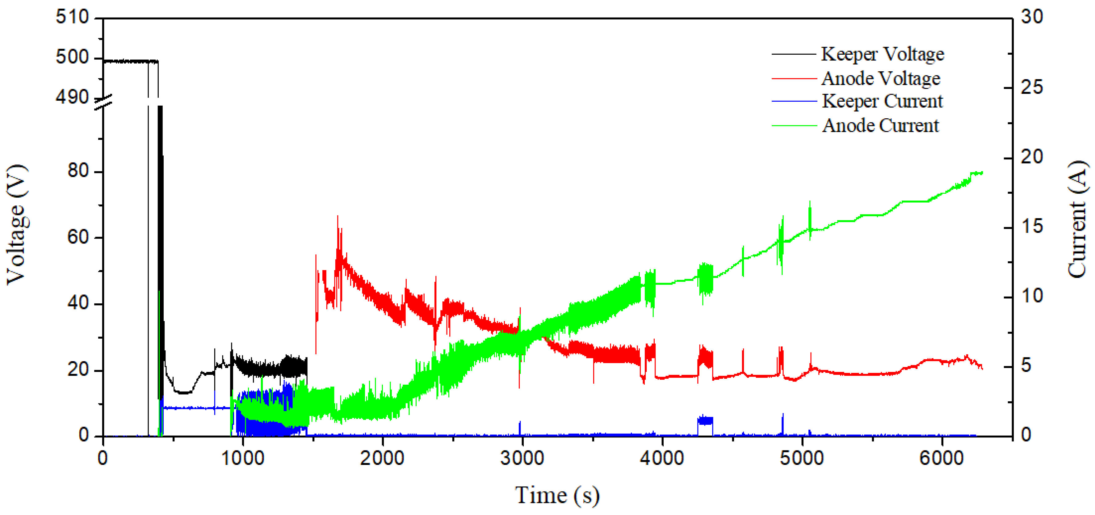
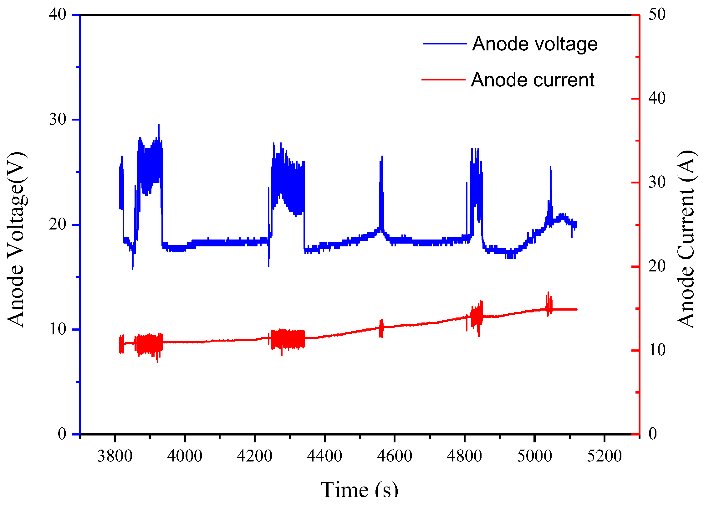
With the increase of the discharge current, the anode voltage demonstrated a transition phenomenon, suddenly increasing from more than 10 volts to about 20 volts, and the shock was serious. 
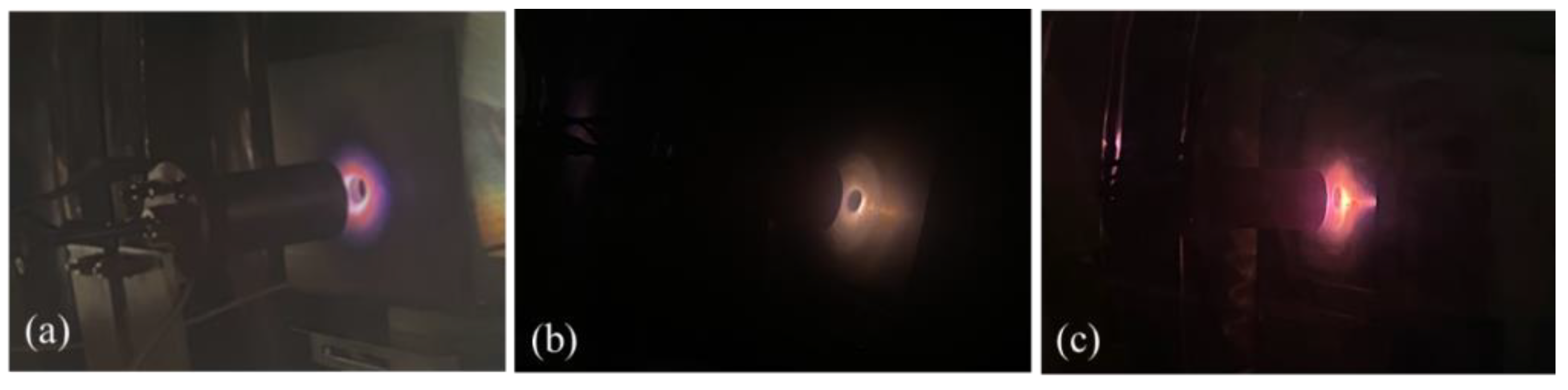
Figure 12 shows the anode voltage jump during high-current operation. The plasma plume at the cathode outlet changed obviously with the change in anode voltage. The cathode was bright violet at start-up and under low-current conditions, as shown in Figure 13a. However, with the increase of the discharge current, the plume color gradually changed to a darker yellow, as shown in Figure 13b. When the voltage transition was high, the cathode plume rapidly changed to a very bright orange color, as shown in Figure 13c. As shown in Figure 12, the simultaneous oscillation of the voltage and current usually lasted for several seconds to tens of seconds and then automatically jumped back to the low-voltage level, and the cathode plume then returned to normal. As the anode current continued to increase, the voltage transition became more frequent, occurring every few minutes. By comparing the appearance of the hollow cathode in Figure 13b,c, it can be seen that the keeper of the C12A7 hollow cathode running at a high voltage shows a red-hot state, indicating that the temperature of the hollow cathode was higher at this time. A long high-voltage discharge duration is obviously detrimental to the performance and lifetime of the C12A7 hollow cathode.
Although the reason for this voltage transition was not clear during the experiment, the discharge state can be actively regulated by the contact keeper power supply. After the anode voltage transition occurred again for about 4200 s, the initially closed contact pole power supply was actively turned on, and the contact pole power supply parameters were about 2 A and 8 V. At this time, the anode voltage did not return to normal, but with the contact pole power supply turned off again, the anode voltage immediately returned to the low-voltage state. At 4800 s and 5100 s, it was confirmed that the switch of keeper power supply could make the C12A7 hollow cathode immediately jump from the high-voltage discharge state to the low-voltage discharge state. When the anode current exceeded 15 A, the phenomenon of automatic voltage transition did not appear again, but the anode voltage value was always high in the discharge process.
After the high-current discharge, the C12A7 hollow cathode was then subjected to repeated ignition experiments to study the effect of a high-current discharge on the starting performance of the C12A7 hollow cathode. The results show that the C12A7 hollow cathode can still start, and the ignition parameters do not change, obviously. Interestingly, the voltage transition occurred again at a 1–4 A low current and the cathode plume was no longer bright violet but dull yellow. This phenomenon implies that the voltage transition problem is not determined by the anode current but is more likely because the discharge behavior at a high current completely changes some key structures of the C12A7 hollow cathode, leading to irreversible changes in its discharge characteristics.
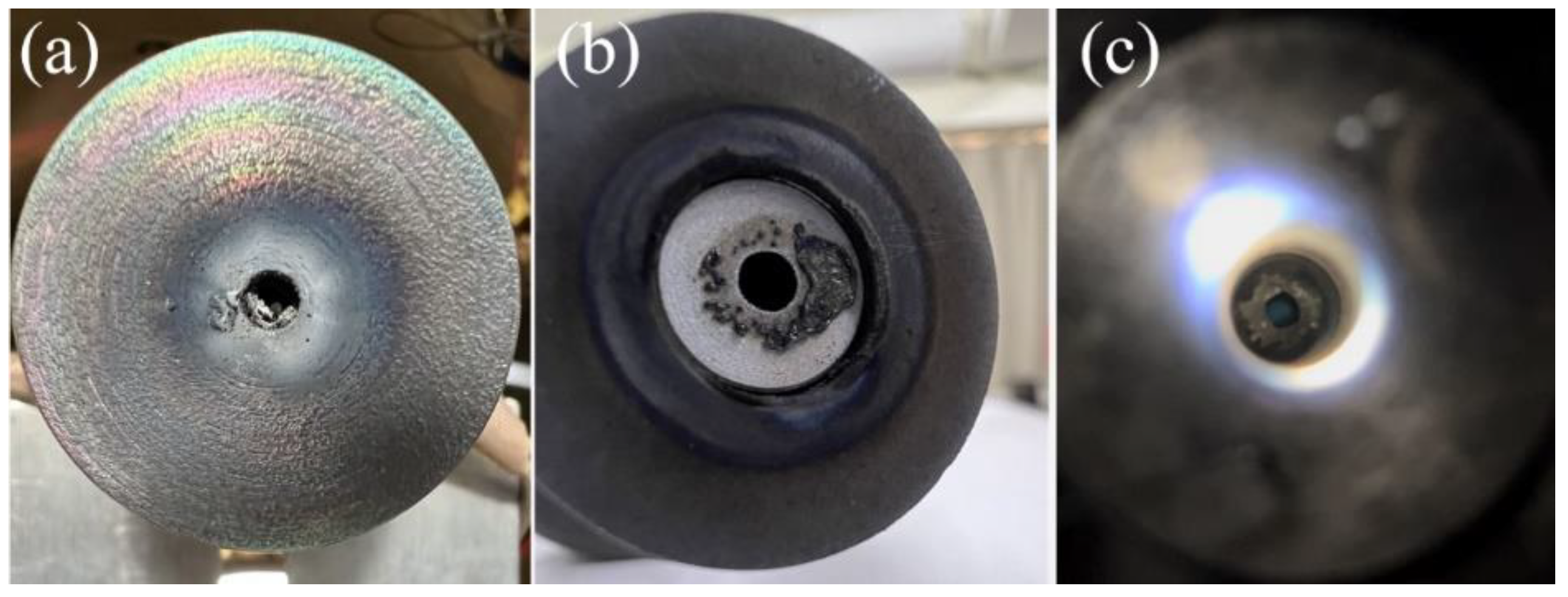
The examination of the C12A7 hollow cathode after the test also confirmed this speculation. As shown in Figure 14a, the area between the keeper and the cathode tube is filled with a large amount of white ash, which may be the residue after the discharge of the emitter. The top of the cathode adheres to the black molten material, which should be the emission of the C12A7 electride after melting, as shown in Figure 14b. The electride emitter in the cathode tube has almost been consumed, and only a small amount of graphite sleeve remains, as shown in Figure 14c. In addition to the increased plasma bombardment heat flux, ohmic heat, caused by its own resistance, may be one of the possible reasons for the serious melting of the electride emitter under high-current conditions. A multimeter was used to measure the resistance values at both ends of the C12A7 electride used in the experiment before discharge. Although the size was the same, the resistance values of different emitters at room temperature were different, and the value was from about tens of ohms to hundreds of ohms. The difference in measured resistance may be related to the surface state of different materials, while the lanthanum hexaboride emitter of the same size was stable at about 0.9Ω. Suppose the phenomenon of the high resistance of C12A7 electride is caused by high body resistivity, such as low electron occupancy in the cage. In that case, the ohmic heat caused by the material’s own resistance will increase exponentially under high-current conditions, which may be the main reason for the large area of melting of the electride emitter under a high current.
After 10 A, the emitter temperature of the C12A7 hollow cathode exceeded the effective range of the colorimetric thermometer. Therefore, the emitter of the C12A7 hollow cathode not only melts at high temperatures under high currents but even flows down to the cathode orifice under the convection of gravity and working medium gas. This explains why the anode voltage switches between the high and low values. Hollow cathode discharge normally occurs between the surface of the emitter and the anode plate in the cathode tube. Once the emitter melts and deforms or even flows out of the cathode orifice, the discharge point of the emitter will be displaced, and the emission area will also change. When the discharge point migrates to the molten body outside the cathode tube (because the effective emission area of this part of the emitter is small), in order to maintain a sufficient amount of thermal emission electrons, the anode voltage will increase, and the higher discharge power will make the emitter temperature higher. Since this mode of decharging occurs outside the cathode tube and between the anode, the plume appears brighter. When a small amount of emitters outside the cathode tube is insufficient to maintain high-current discharge or when the contact pole power is turned on, the discharge point will be transferred to the emitter inside the cathode tube again. The effective emission area of this part of the emitter is larger, and only a lower discharge power is needed to maintain the thermal emission temperature and, thus, the anode voltage is low. Because the discharge point is in the cathode tube, the small orifice of the cathode blocks the discharge plume, and therefore, the color of the plume is relatively dim.
However, if the high resistance of the C12A7 electride is caused by high surface resistivity, then the ohmic heat may not be serious because the high-resistance insulating layer on the surface of the emitter is gradually removed during discharge. Since the resistance values of different C12A7 emitters before and after discharge vary greatly, which is obviously related to the discharge conditions experienced and the material’s surface state, the high-resistance behavior of C12A7 electride is more likely to be caused by the change in the surface layer structure. The total working time of a C12A7 hollow cathode under the conditions of a high current (more than 10 A) is not more than two hours, and the emitter in the cathode tube will almost be consumed; such a short life means that a C12A7 hollow cathode under the condition of a high current is difficult to utilize in practical applications.

4. Conclusions

As a new cathode technology, the C12A7 hollow cathode must be verified for its actual working performance and practical application potential. In this research, the effect of its working current on the C12A7 hollow cathode was studied by conducting an experiment and simulation. The results are as follows:
1. The C12A7 hollow cathode works well under low-current conditions. The C12A7 hollow cathode of the current configuration has a maximum safe current of 4 A. It should be pointed out that the working performance of the hollow cathode is affected by many factors, such as cathode structure, orifice size, working current, and cathode material. If it is necessary to increase the safe operating current, further consideration can be given to optimizing the heat dissipation structure and materials. Compared with the traditional Lab6 and Bao-W cathode, the expansion of the cathode orifice can reduce the risk of overheating to a certain extent and may be more suitable for the open-orifice hollow cathode configuration.
2. The voltage transition phenomenon of the C12A7 hollow cathode under high-current conditions (more than 10 A) changed some key structures of the C12A7 hollow cathode, resulting in irreversible changes in its discharge characteristics. The electride emitter may melt in a large area under high-current conditions. The short working lifetime under high-current conditions means that the C12A7 hollow cathode is difficult to apply in practical applications under high-current conditions.

Author Contributions

Conceptualization, Y.H., G.C. and P.W.; methodology, Y.H. and X.W.; software, Y.H.; validation, X.W.; formal analysis, Y.H.; investigation, X.W.; data curation, Y.H.; writing—original draft preparation, Y.H.; writing—review and editing, Y.H. and X.W.; visualization, D.C.; project administration, P.W. All authors have read and agreed to the published version of the manuscript.

Funding

This work is supported by Joint Fund for Equipment Pre-research and Aerospace Science and Technology, Grant/Award Number: [6141B061203].

Data Availability Statement

Not applicable.

Conflicts of Interest

The authors declare no conflict of interest.

References

  1. Dale, E.; Jorns, B.; Gallimore, A. Future directions for electric propulsion research. Aerospace 2020, 7, 120. [Google Scholar] [CrossRef]
  2. Iess, L.; Bruno, C.; Ulivieri, C.; Ponzi, U.; Parisse, M.; Laneve, G.; Vannaroni, G.; Dobrowolny, M.; De Venuto, F.; Bertotti, B.; et al. Satellite de-orbiting by means of electrodynamic tethers part i: General concepts and requirements. Acta Astronaut. 2002, 50, 399–406. [Google Scholar] [CrossRef]
  3. Lev, D.; Myers, R.M.; Lemmer, K.M.; Kolbeck, J.; Koizumi, H.; Polzin, K. The technological and commercial expansion of electric propulsion. Acta Astronaut. 2019, 159, 213–227. [Google Scholar] [CrossRef]
  4. Lev, D.R.; Mikellides, I.G.; Pedrini, D.; Goebel, D.M.; Jorns, B.A.; McDonald, M.S. Recent progress in research and development of hollow cathodes for electric propulsion. Plasma Phys. 2019, 3, 6. [Google Scholar] [CrossRef]
  5. Rand, L.; Williams, J.; Hoyt, R. Hollow Cathode with Electride Insert. In Proceedings of the AIAA/ASME/SAE/ASEE Joint Propulsion Conference & Exhibit, San Diego, CA, USA, 31 July–3 August 2011. [Google Scholar]
  6. Drobny, C.; Tajmar, M. Development of a C12A7 Electride Hollow Cathode. In Proceedings of the 52nd AIAA/SAE/ASEE Joint Propulsion Conference, Salt Lake City, UT, USA, 25–27 July 2016; p. 3124751. [Google Scholar]
  7. Mcdonald, M.S.; Caruso, N.R. Ignition and early operating characteristics of a low-current C12A7 hollow cathode. In Proceedings of the 35th International Electric Propulsion Conference (IEPC), Atlanta, GA, USA, 8–12 October 2017. [Google Scholar]
  8. Drobny, C.; Wulfkühler, J.P.; Tajmar, M. Development of a C12A7 Electride Hollow Cathode and Joint Operation with a Plasma Thruster. In Proceedings of the 36th International Electric Propulsion Conference, Vienna, Austria, 15–20 September 2019. [Google Scholar]
  9. Drobny, C.; Wulfkühler, J.-P.; Wätzig, K.; Tajmar, M. Endurance Test of a Hollow Cathode Using the Emitter Material C12A7 Electride. In Proceedings of the Space Propulsion 2020+1, Virtual, 17–19 March 2021. [Google Scholar]
  10. Wätzig, K.; Drobny, C.; Tajmar, M. Improved Thermal and Mechanical Properties of [Ca24Al28O64]4+(4e) Electride Ceramic by Adding Mo Metal. Adv. Eng. Mater. 2022, 25, 2201286. [Google Scholar] [CrossRef]
  11. Toledo, J.; Plaza, J.F.; Post, A.; Zschätzsch, D.; Reitemeyer, M.; Chen, L.; Gurciullo, A.; Siegl, A.; Klar, P.J.; Lascombes, P.; et al. Performance comparison of LaB6 and C12A7:e-emitters for space electric propulsion cathodes. Mater. Sci. Eng. 2022, 1226, 012093. [Google Scholar] [CrossRef]
  12. Hua, Z.; Wang, P.; Luo, Z.; Zhang, X.; Tian, L. An expermental study on the degradation of the C12A7 hollow cathode. Plasma Sci. Technol. 2022, 24, 074010. [Google Scholar] [CrossRef]
  13. Hua, Z.; Wang, P.; Xu, Z.; Yu, S. Experimental characterization of the C12A7 hollow cathode and its joint operation with a low-power Hall thruster. Vacuum 2021, 192, 110443. [Google Scholar] [CrossRef]
  14. Gabriel, S.B. COMSOL Modelling of Hollow Cathodes. In Proceedings of the 35th International Electric Propulsion Conference, IEPC2017, Georgia Institute of Technology, Atlanta, GA, USA, 8–12 October 2017. [Google Scholar]
  15. Liu, H.; Li, M.; Ning, Z.; Ren, J.; Tang, H.; Yu, D.; Demidov, E.V.; Eliseev, S.I.; Kudryavtsev, A.A. 2-D Modeling of Orificed Hollow Cathodes of Stationary Plasma Thrusters SPT-100. IEEE Trans. Plasma Sci. 2015, 43, 12–43. [Google Scholar] [CrossRef]
  16. Batsaikhan, E. Simulation of Hollow Cathode Discharge Based on COMSOL; Harbin Institute of Technology: Harbin, China, 2020. [Google Scholar]
  17. Thompson, S.J.; VanGermert, J.J.; Farnell, C.C.; Farnell, C.C.; Farnell, S.C.; Hensen, T.J.; Ham, R.; Williams, D.D.; Chandler, J.P.; Williams, J.D. Development of an Iodine Compatible Hollow Cathode. In Proceedings of the AIAA Propulsion and Energy 2019 Forum, (Indianapolis, IN: AIAA), Indianapolis, IN, USA, 19–22 August 2019. [Google Scholar]
  18. Waetzig, K.; Schilm, J. Electronic, mechanical, and thermal properties of [Ca24Al28O64]4+(4e) electride ceramic. Int. J. Ceram. Eng. Sci. 2021, 3, 165–172. [Google Scholar] [CrossRef]
  19. Zhang, X.; Feng, Q.; Zhao, J.; Liu, H.; Li, J.; Xiao, Y.; Li, F.; Lu, Q. Sr-doping enhanced electrical transport and thermionic emission of single crystal 12CaO⋅7Al2O3 electride. Curr. Appl. Phys. 2020, 20, 96. [Google Scholar] [CrossRef]
  20. Domonkos, M.T. Evaluation of Low-Current Orificed Hollow Cathodes; University of Michigan: Ann Arbor, MI, USA, 1999. [Google Scholar]
  21. Lev, D.; Appel, L. Heaterless Hollow Cathode Technology—A Critical Review. In Proceedings of the Space Propulsion Conference, Rome, Italy, 2–6 May 2016. [Google Scholar]
  22. Aston, G. Test Bed Ion Engine Development; National Aeronautics and Space Administration, Lewis Research Center: Cleveland, OH, USA, 1984. [Google Scholar]
Figure 1. C12A7 emitter and C12A7 hollow cathode.
Aerospace 10 00339 g001
Figure 2. Vacuum chamber and experimental equipment.
Aerospace 10 00339 g002
Figure 3. Electrical schematic of the heaterless C12A7 hollow cathode.
Aerospace 10 00339 g003
Figure 4. C12A7 hollow cathode model.
Aerospace 10 00339 g004
Figure 5. Mesh generation of hollow cathode model.
Aerospace 10 00339 g005
Figure 6. Schematic of the temperature measurement of the electride insert.
Aerospace 10 00339 g006
Figure 7. The volt–ampere characteristics curve of the C12A7 hollow cathode at a wide range of currents.
Aerospace 10 00339 g007
Figure 8. C12A7 hollow cathode working under low-current operating conditions.
Aerospace 10 00339 g008
Figure 9. (a) Contours of atom number density distribution of C12A7 hollow cathode with cathode orifice 1 mm. (b) Contours of atom number density distribution of C12A7 hollow cathode with cathode orifice 3 mm. (c) Atom density variation on the symmetry axis along the Z-direction.
Aerospace 10 00339 g009aAerospace 10 00339 g009b
Figure 10. (a) Contours of electron number density distribution of C12A7 hollow cathode with cathode orifice 1 mm. (b) Contours of electron number density distribution of C12A7 hollow cathode with cathode orifice 3 mm. (c) Electron number density variation on the symmetry axis along the Z-direction.
Aerospace 10 00339 g010
Figure 11. Axial temperature of the emitter along the axis of symmetry in the Z-direction.
Aerospace 10 00339 g011
Figure 12. Anode voltage jump during the high-current operation.
Aerospace 10 00339 g012
Figure 13. Plasma state variation during the high-current test. (a) Violet plasma cone with an anode current of 5 A. (b) Fading orange glow, Ia = 15 A, Va = 19 V. (c) Bright orange glow, Ia = 15 A, Va = 26 V.
Aerospace 10 00339 g013
Figure 14. Critical components of C12A7 hollow cathode after discharge at high current. (a) The keeper plate. (b) Cathode orifice plate. (c) Internal area of cathode tube.
Aerospace 10 00339 g014
Table 1. Thermal diffusion coefficient and specific heat capacity of C12A7 electride at different temperatures.
Temp (K)α (cm2/s)Cp (J/g/K)
305.58.063 × 10−39.224 × 10⁻¹
374.57.606 × 10−31.017
473.26.932 × 10−31.172
573.57.028 × 10−31.199
673.37.067 × 10−31.256
773.17.166 × 10−31.372
Table 2. Thermal conductivity of C12A7 electride at different temperatures.
Temp (K)K (W/m·K)
305.51.6553
374.51.7216
473.21.8082
573.51.8755
673.31.9756
773.12.1883
Table 3. Comparison of measured and calculated values of the insert operating temperature.
OrderMass Flow Rate
(sccm)
Anode Current
(A)
Operation Duration
(min)
Operating Temperature
(K)
Simulated Temperature
(K)
Relative Error
110120135313043.6
210210138713641.6
410310141314401.9
5103.510149914692.0
610410154815201.8
810510163316021.9
Disclaimer/Publisher’s Note: The statements, opinions and data contained in all publications are solely those of the individual author(s) and contributor(s) and not of MDPI and/or the editor(s). MDPI and/or the editor(s) disclaim responsibility for any injury to people or property resulting from any ideas, methods, instructions or products referred to in the content.

