
Multidisciplinary Design and Optimization of Variable Camber Wing with Non-Equal Chord

Abstract
:1. Introduction
2. Design of Trailing Edge Deflection Mechanism
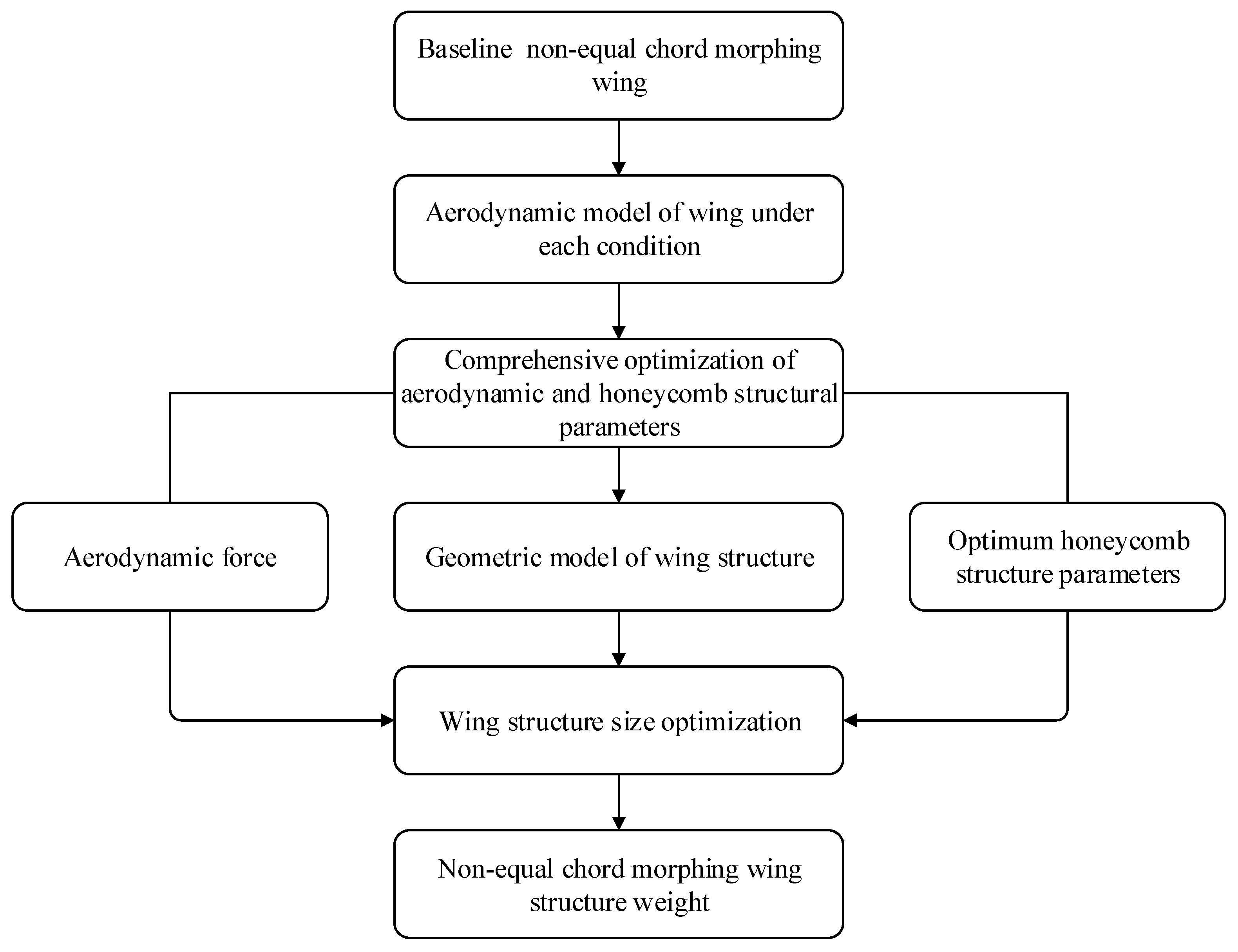
3. Multidisciplinary Optimization Framework for Non-Equal Chord Morphing Wing
4. Comprehensive Optimization of Aerodynamics and Honeycomb Structure Parameters
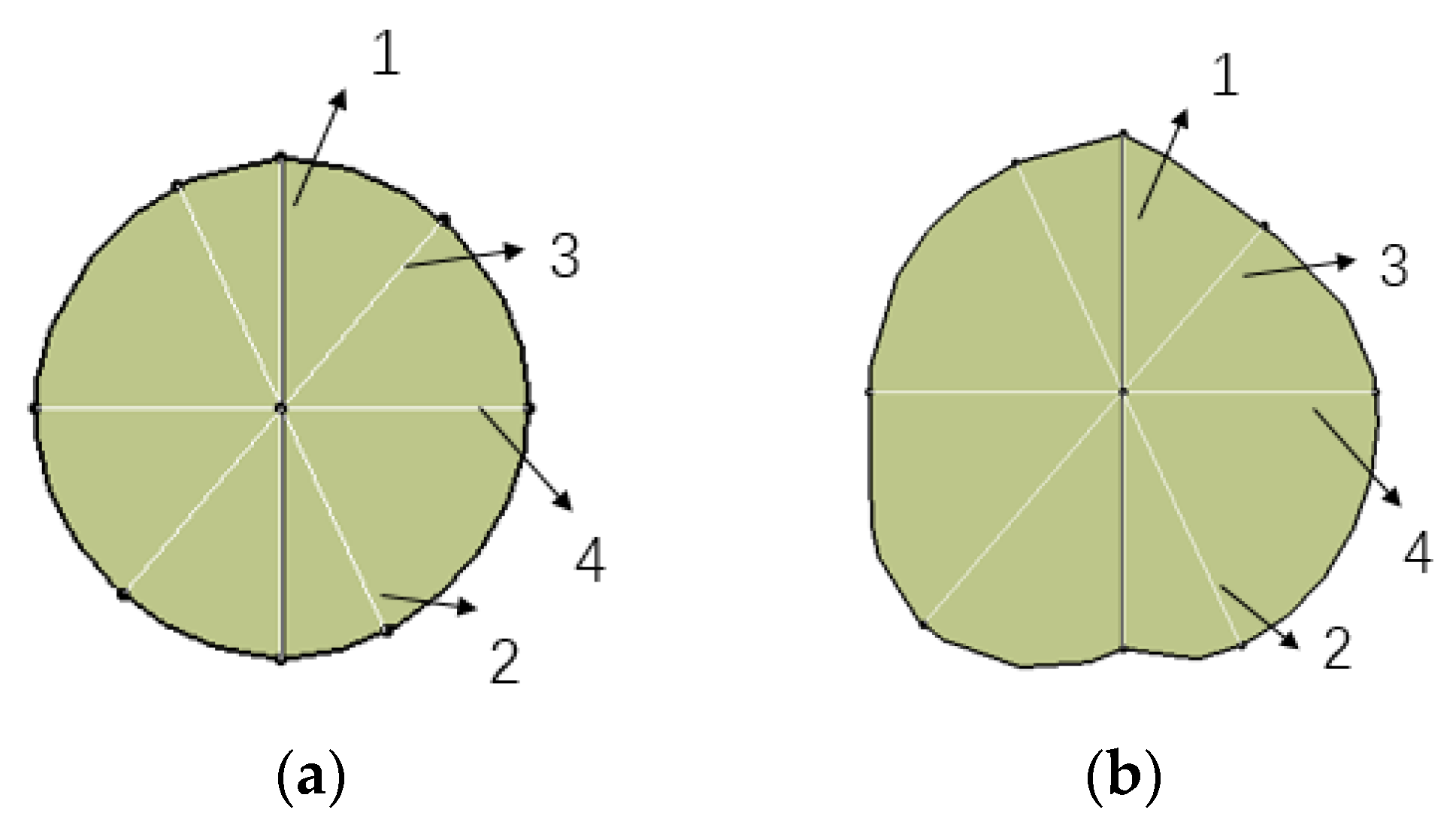
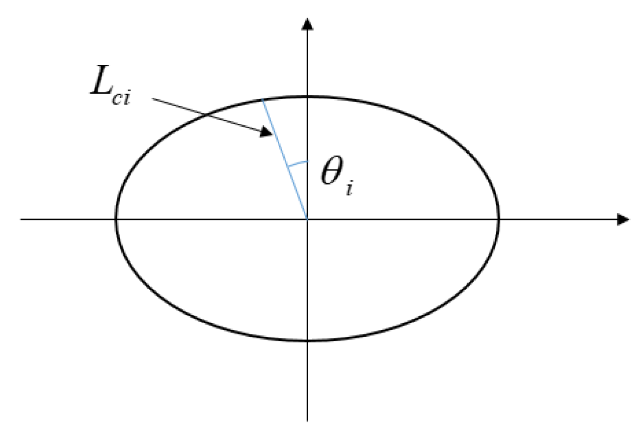
4.1. Aerodynamic Model of the Wing
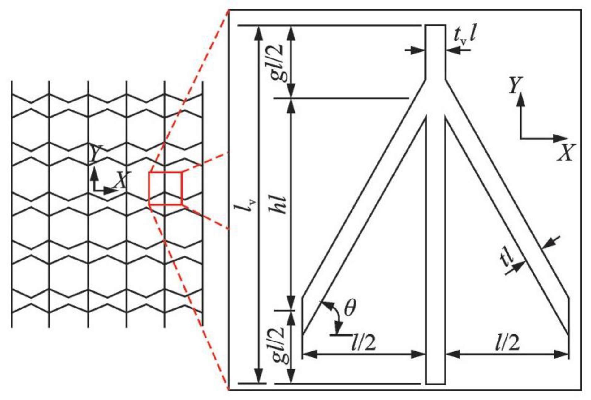
4.2. Equivalent Parameters of Honeycomb Structure with Zero Poisson’s Ratio
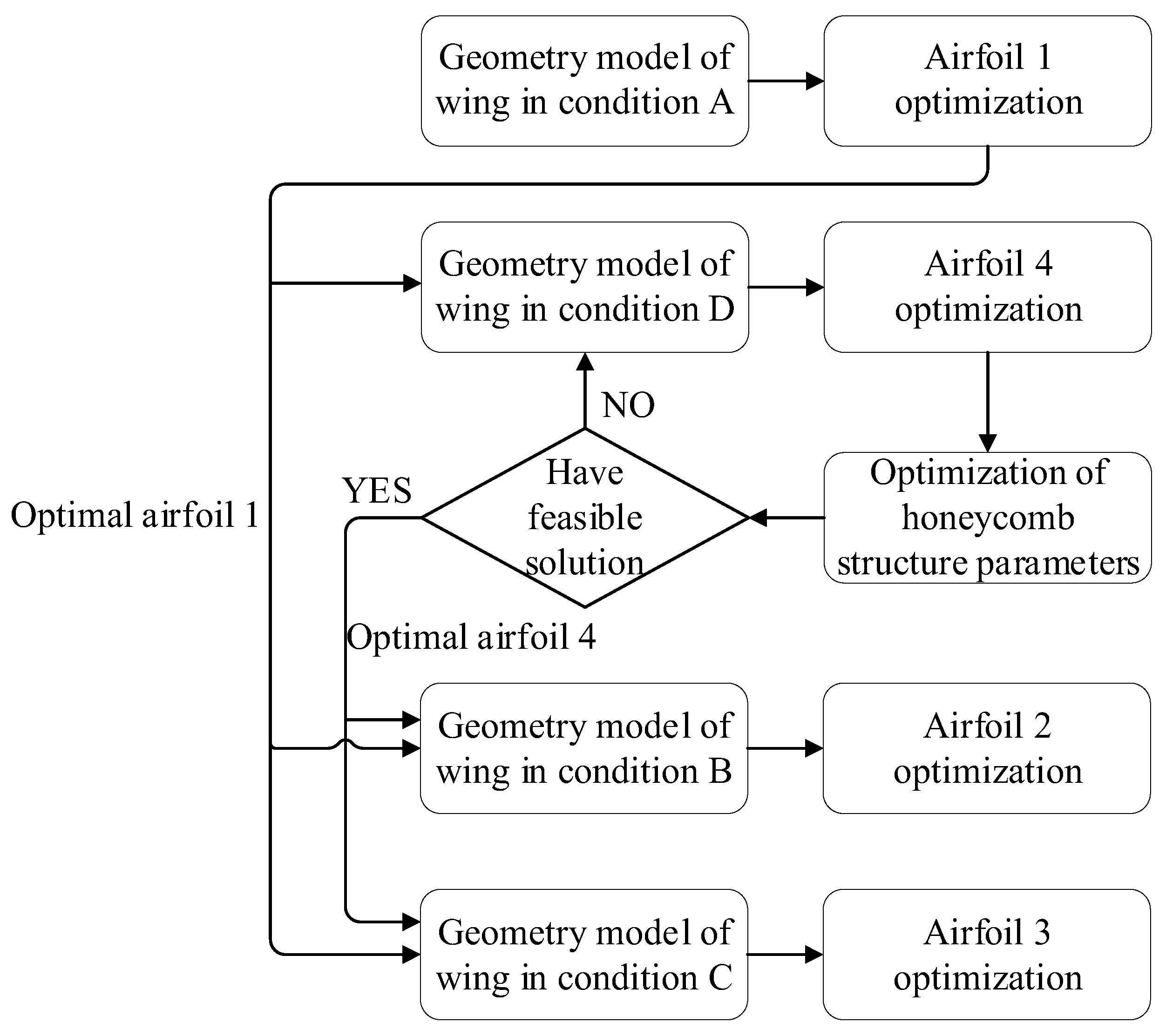
4.3. Comprehensive Optimization
- (1)
- Condition A
- (2)
- Condition D
- (3)
- Condition B
- (4)
- Condition C
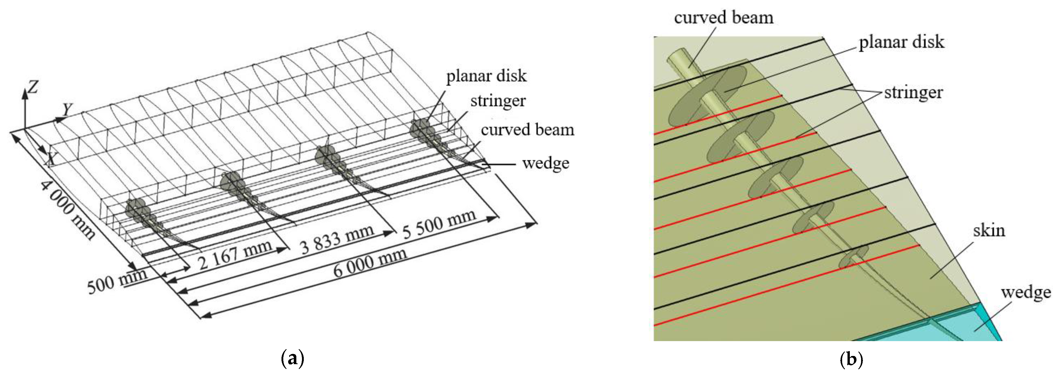
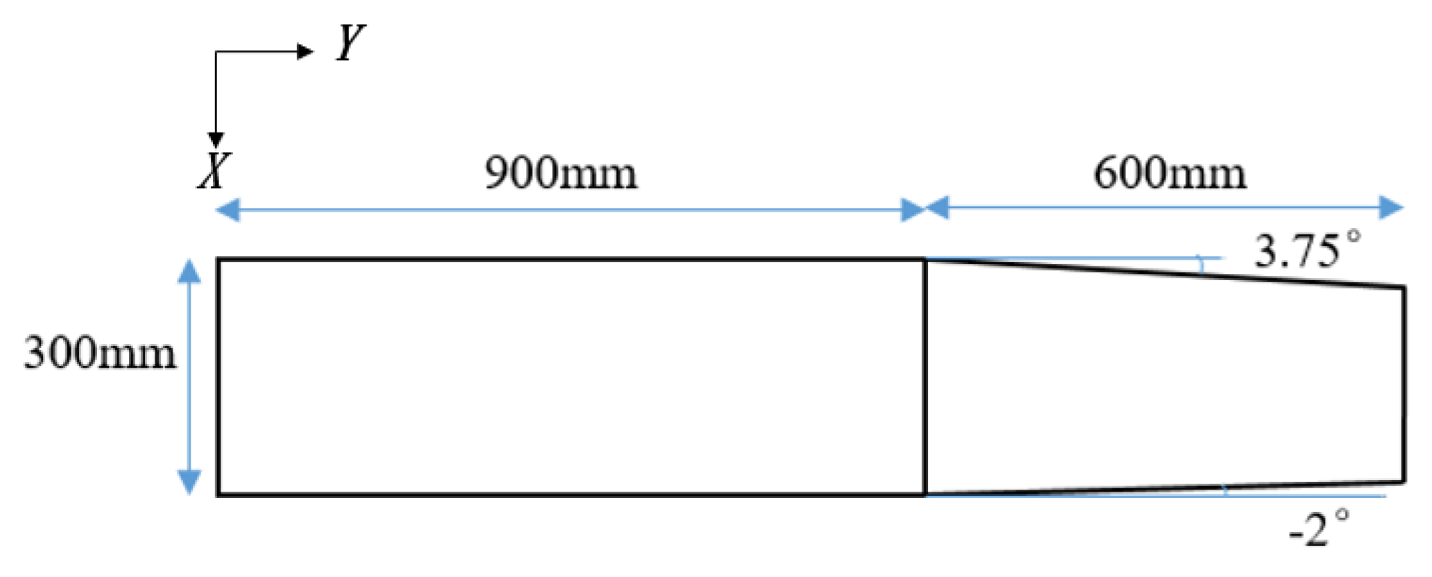
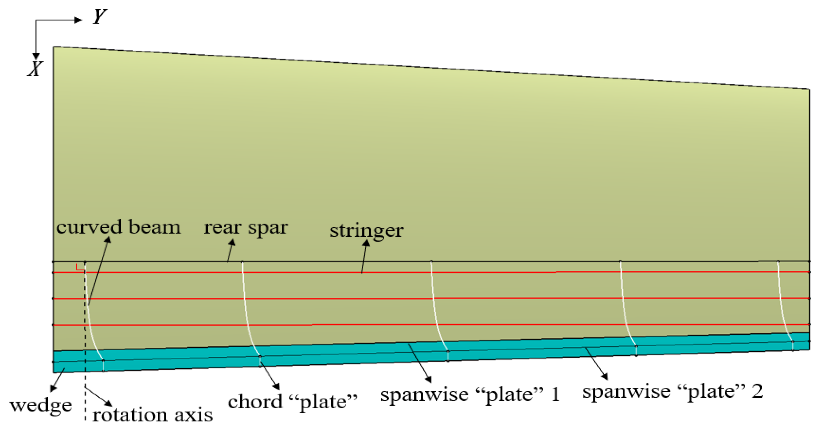
5. Non-Equal Chord Wing Structure Model
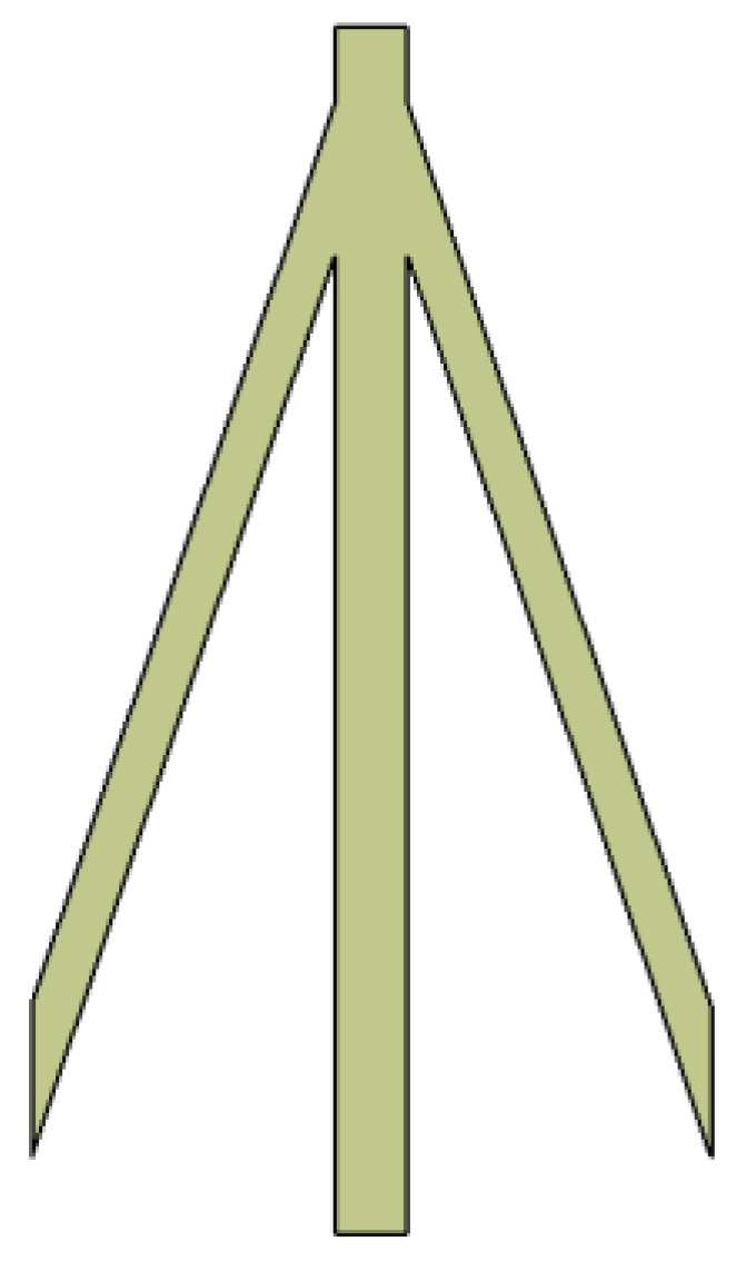
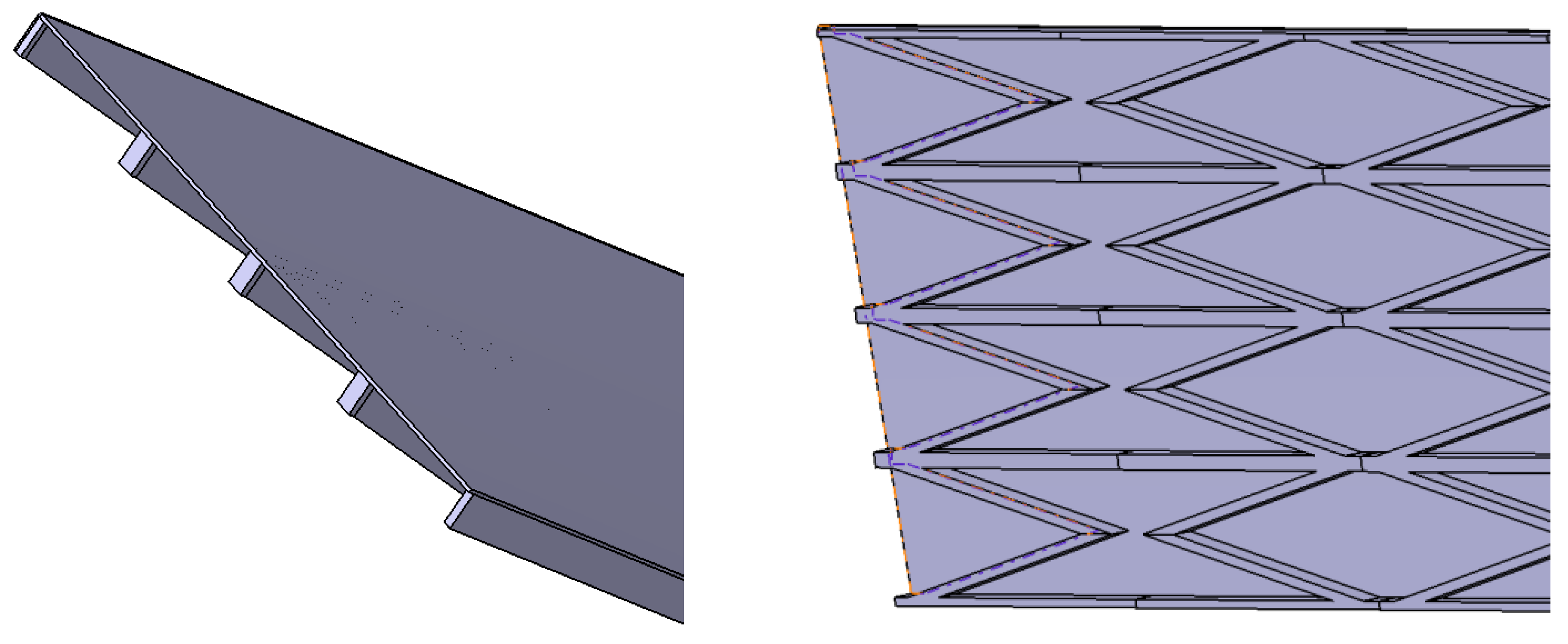
5.1. Wing Structure Design
5.2. Definition of Structural Optimization Problems
6. Results and Analysis of Multidisciplinary Optimization
- (1)
- Aerodynamic optimization
- (2)
- Optimization of honeycomb structure parameters
- (3)
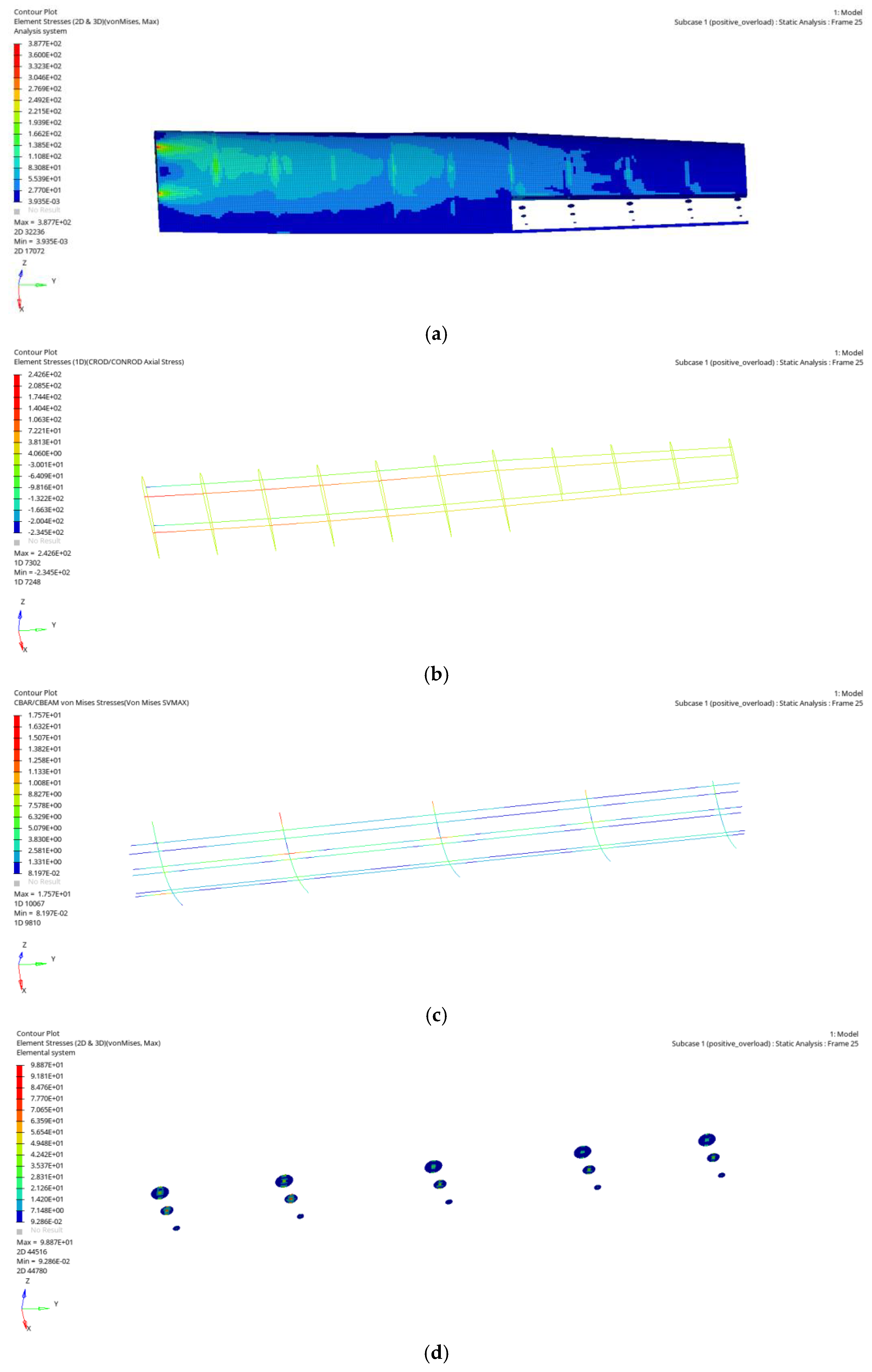
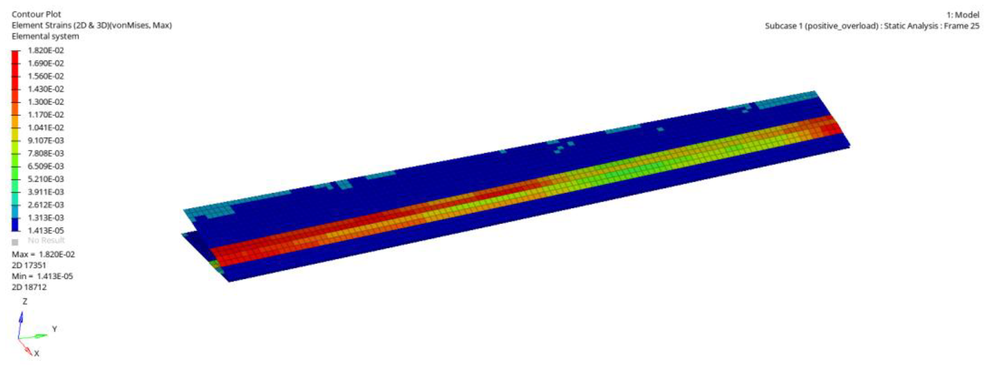
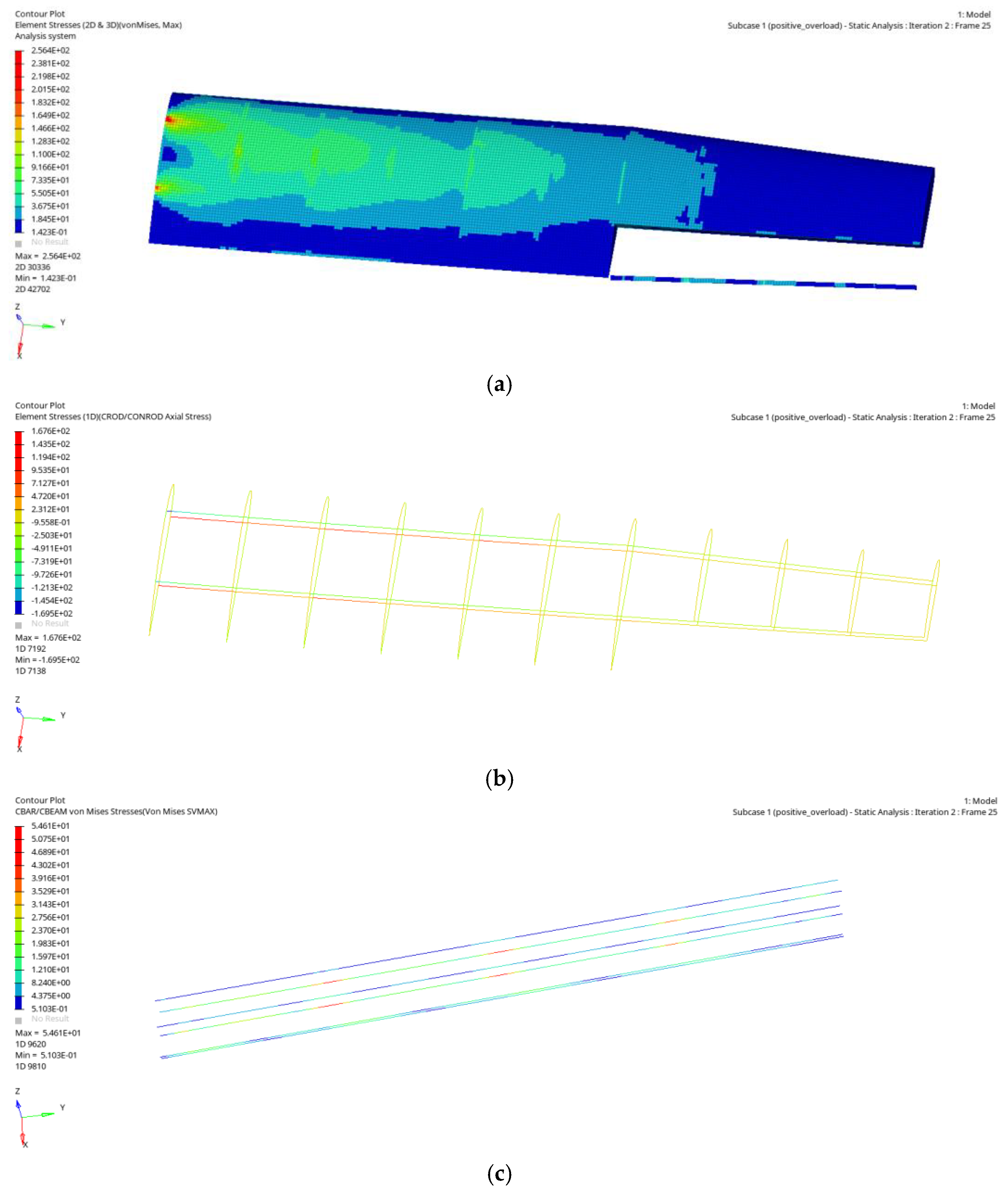
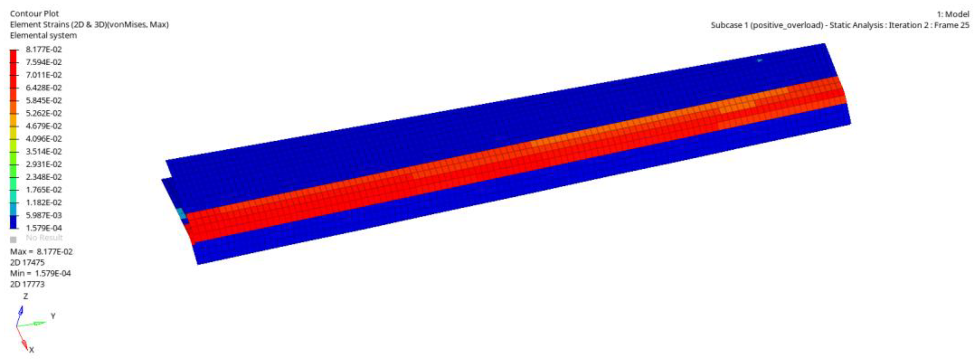
- Wing structure optimization
7. Conclusions
Author Contributions
Funding
Data Availability Statement
Conflicts of Interest
References
- Li, D.C.; Zhao, S.W.; Ronch, A.D.; Xiang, J.; Drofelnik, J.; Li, Y.; Zhang, L.; Wu, Y.; Kintscher, M.; Monner, H.P.; et al. A review of modelling and analysis of morphing wings. Prog. Aerosp. Sci. 2018, 100, 46–62. [Google Scholar] [CrossRef] [Green Version]
- Miller, E.J.; Lokos, W.A.; Cruz, J.; Crampton, G.; Craig, A. Approach for Structurally Clearing an Adaptive Compliant Trailing Edge Flap for Flight; Society of Flight Test Engineers International Annual Symposium; NASA: Washington, DC, USA, 2015.
- Monner, H.P. Realization of an optimized wing camber by using formvariable flap structures. Aerosp. Sci. Technol. 2001, 5, 445–455. [Google Scholar] [CrossRef]
- Campanile, L.F.; Sachau, D. The Belt-Rib Concept: A Structronic Approach to Variable Camber. J. Intell. Mater. Syst. Struct. 2000, 11, 215–224. [Google Scholar] [CrossRef]
- Campanile, L.F.; Seack, O.; Sachau, D. Belt-rib concept for variable-camber airfoils: Recent developments. Smart Struct. 2000, 3985, 110–120. [Google Scholar]
- Woods, B.K.; Bilgen, O.; Friswell, M.I. Wind tunnel testing of the fish bone active camber morphing concept. J. Intell. Mater. Syst. Struct. 2014, 25, 772–785. [Google Scholar] [CrossRef]
- Morishima, R.; Guo, S.J.; Ahmed, S. A Composite Wing with a Morphing Leading Edge. In Proceedings of the 51st AIAA/ASME/ASCE/AHS/ASC Structures, Structural Dynamics and Materials Conference, Orlando, FL, USA, 12–15 April 2010; pp. 7865–7878. [Google Scholar]
- Li, D.C.; Guo, S.J.; Aburass, T.O.; Yang, D.; Xiang, J. Active control design for an unmanned air vehicle with a morphing wing. Aircr. Eng. Aerosp. Technol. 2016, 88, 168–177. [Google Scholar] [CrossRef]
- Yokozeki, T.; Sugiura, A.; Hirano, Y. Development of Variable Camber Morphing Airfoil Using Corrugated Structure. J. Aircr. 2014, 51, 1023–1029. [Google Scholar] [CrossRef] [Green Version]
- Yokozeki, T.; Sugiura, A.; Hirano, Y. Development and wind tunnel test of variable camber morphing wing. In Proceedings of the 22nd AIAA/ASME/AHS Adaptive Structures Conference, National Harbor, MD, USA, 13–17 January 2014. [Google Scholar]
- Takahashi, H.; Yokozeki, T.; Hirano, Y. Development of variable camber wing with morphing leading and trailing sections using corrugated structures. J. Intell. Mater. Syst. Struct. 2016, 27, 2827–2836. [Google Scholar] [CrossRef]
- Li, Y.Z.; Ge, W.J.; Zhou, J.; Zhang, Y.; Zhao, D.; Wang, Z.; Dong, D. Design and experiment of concentrated flexibility-based variable camber morphing wing. Chin. J. Aeronaut. 2022, 35, 455–469. [Google Scholar] [CrossRef]
- Zhang, Y.Q.; Ge, W.J.; Zhang, Z.A.; Mo, X.; Zhang, Y. Design of compliant mechanism-based variable camber morphing wing with nonlinear large deformation. Int. J. Adv. Robot. Syst. 2019, 16, 1729881419886740. [Google Scholar] [CrossRef]
- Balaji, S. Evaluation and Delineations of Multi Segment Variable Camber Fixed Wing for Unmanned Aerial Vehicles. Fluid Mech. Open Access 2018, 5, 186. [Google Scholar]
- Zhao, A.M.; Hui, Z.; Liu, D.S.; Liu, B.F. Structure design of an innovative adaptive variable camber wing. MATEC Web Conf. 2018, 151, 04003. [Google Scholar] [CrossRef] [Green Version]
- Zhao, A.M.; Hui, Z.; Hai, C.J.; Dong, S.W. Structural design and verification of an innovative whole adaptive variable camber wing. Aerosp. Sci. Technol. 2019, 89, 11–18. [Google Scholar] [CrossRef]
- Chen, T.G.; Jiang, J.; Zhang, Q.; Wang, H.L.; Zhang, X.Y. Experiments and modeling of variable camber guide vane embedded with shape memory alloy plate. Smart Mater. Struct. 2021, 30, 045012. [Google Scholar] [CrossRef]
- Olympio, K.; Gandhif, F. Flexible skins for morphing aircraft using cellular honeycomb cores. J. Intell. Mater. Syst. Struct. 2010, 21, 1719–1735. [Google Scholar] [CrossRef]
- Alderson, A.; Alderson, K.L.; Chiriam, G.; Ravirala, N.; Zied, K. The in-plane linear elastic constants and out-of plane bending of 3-coordinated ligament and cylinderligament honeycombs. Compos. Sci. Technol. 2010, 70, 1034–1041. [Google Scholar] [CrossRef] [Green Version]
- Huang, J.; Zhang, Q.H.; Scarpa, F.; Liu, Y.; Leng, J. Bending and benchmark of zero Poisson’s ratio cellular structures. Compos. Struct. 2016, 152, 729–736. [Google Scholar] [CrossRef] [Green Version]
- Kulfan, B.M.; Bussoletti, J.E. “Fundamental” parametric geometry representations for aircraft component shapes. In Proceedings of the 11th AIAA/ISSMO Multidisciplinary Analysis and Optimization Conference 2006-6948, Portsmouth, VA, USA, 6–8 September 2006. [Google Scholar]
- Aftosmis, M.J.; Bbeger, M.J.; Melton, J.E. Robust and Efficient Cartesian Mesh Generation for Component-Based Geometry. AIAA J. 1998, 36, 925–960. [Google Scholar] [CrossRef]
- Cummings, R.M.; Mason, W.H.; Morton, S.A.; McDaniel, R. Applied Computational Aerodynamics: A Modern Engineering Approach; Cambridge University Press: Cambridge, UK, 2015. [Google Scholar]
- Liu, W.; Li, H. Equivalent Moduli of Accordion Honeycomb with Zero Poisson’s Ratio. Chin. J. Solid Mech. 2018, 39, 100–112. [Google Scholar]
- Timoshenko, S.P.; Gere, J.M.; Cusens, A.R. Mechanics of Materials; Van Nostrand Reinhold Company: New York, NY, USA, 1972. [Google Scholar]
- Yu, K.P.; Zhou, C.Y.; Tan, H.F. HyperMesh from Entry to Mastery; Science Press: Beijing, China, 2005. [Google Scholar]
- Sheng, J.H.; Xu, Y.D.; Han, J.; Jia, Z.Y. Size Optimization Design for Cantilever Structure of an Ammunition Supply Truck Based on Optistruct. In Proceedings of the 2019 4th International Conference on Automation, Control and Robotics Engineering, Shenzhen, China, 19–21 July 2019. [Google Scholar]
- Liu, L.L.; Jiang, W.; Liu, Z.W.; Yu, R.X.; Bian, T. Multi-objective optimization of shaftless rim-driven thruster based on ISIGHT. J. Phys. Conf. Ser. 2022, 2369, 012023. [Google Scholar] [CrossRef]


| Condition | Flight Altitude | Mach Number Ma Flight Speed V | Angle of Attack | Flight State | Airfoil of Outer Wing |
|---|---|---|---|---|---|
| A | 1 km | Ma = 0.3 | 0° | Cruise | The left and right sides are airfoil 1 |
| B | 1 km | Ma = 0.2 | 0° | Cruise | The left and right sides are airfoil 2 |
| C | 1 km | Ma = 0.2 | 0° | Roll | One side is airfoil 3; the other side is airfoil 4 |
| D | 0 km | V = 40 m/s | 13° | Take-off and landing | The left and right sides are airfoil 4 |
| Curved Beam Number | Distance/mm |
|---|---|
| 1 | 25 |
| 2 | 150 |
| 3 | 300 |
| 4 | 450 |
| 5 | 575 |
| Design Variable | Lower Limit | Upper Limit |
|---|---|---|
| USij, LSij | 0.5 mm | 4 mm |
| FSWij, BSWij | 0.5 mm | 5 mm |
| FSRij, BSRij | 10 mm2 | 50 mm2 |
| RW1, RW2 | 0.5 mm | 5 mm |
| RR1, RR2 | 10 mm2 | 30 mm2 |
| SRW1 | 1 mm | 5 mm |
| SRR1 | 20 mm2 | 50 mm2 |
| UHS1, LHS1 | 2 mm | 5 mm |
| UHS2, LHS2 | 2 mm | 5 mm |
| UHS3, LHS3 | 2 mm | 3 mm |
| UHS4, LHS4 | 1 mm | 2 mm |
| JPUS, JPLS | 0.5 mm | 1 mm |
| JPX1, JPX2, JPY | 0.5 mm | 2 mm |
| CBm1 | 0.5 mm | 4 mm |
| CBm2 | 0.5 mm | 3 mm |
| CBm3 | 0.5 mm | 2 mm |
| CBm4 | 0.5 mm | 1.5 mm |
| Pm1 | 0.5 mm | 4 mm |
| Pm2 | 0.5 mm | 3 mm |
| Pm3 | 0.5 mm | 2 mm |
| h/mm | b1/mm | b2/mm | t1/mm | t2/mm | t3/mm | |
|---|---|---|---|---|---|---|
| stringer 1 | 6 | 5 | 5 | 0.5 | 0.5 | 0.5 |
| stringer 2 | 4 | 4 | 4 | 0.5 | 0.5 | 0.5 |
| stringer 3 | 3 | 3 | 3 | 0.5 | 0.5 | 0.5 |
| Flight Condition | Performance Index | Constraint Condition |
|---|---|---|
| condition A (0.3 Ma cruise) | displacement of wing tip in Z-direction/mm | ≤75 |
| stress of wing structure using duralumin/MPa | ≤390 | |
| strain of flexible skin at trailing edge of outer segment wing/με | ≤99,109 | |
| first-order instability factor | ≥0.8 | |
| condition D (take-off and landing) | displacement of wing tip in Z-direction/mm | ≤75 |
| stress of wing structure using duralumin/MPa | ≤390 | |
| strain of flexible skin at trailing edge of outer segment wing/με | ≤99,109 | |
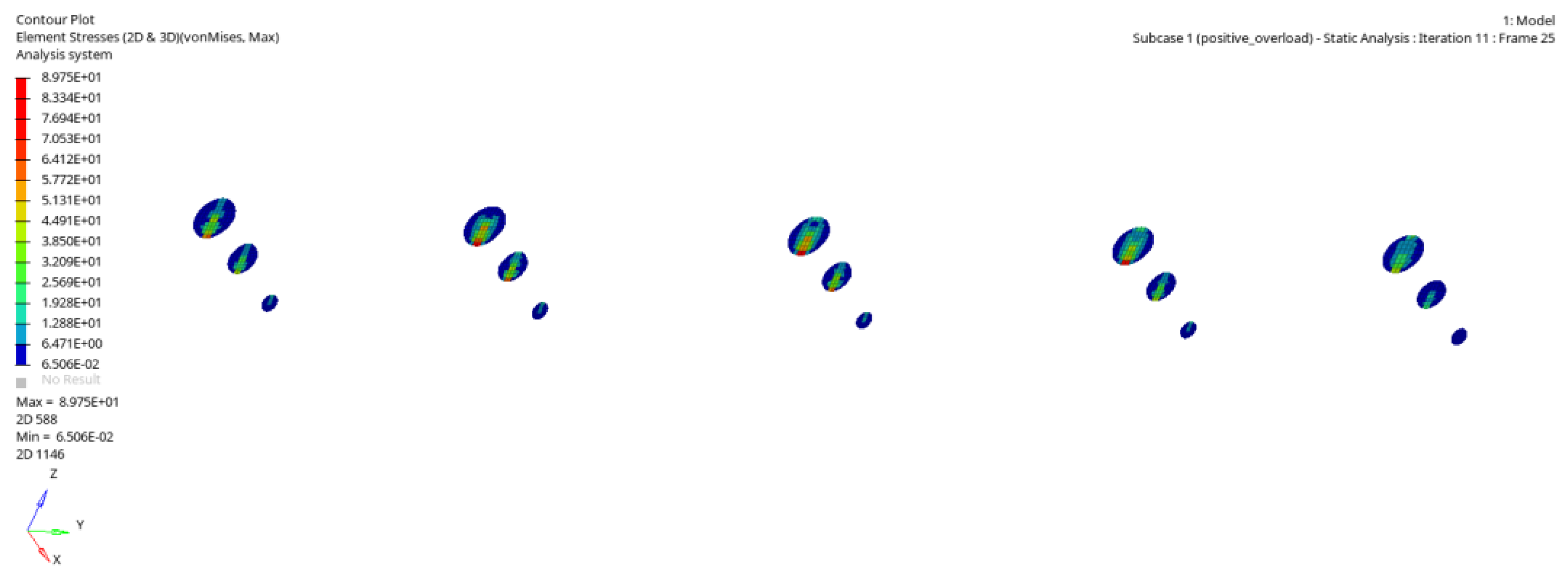
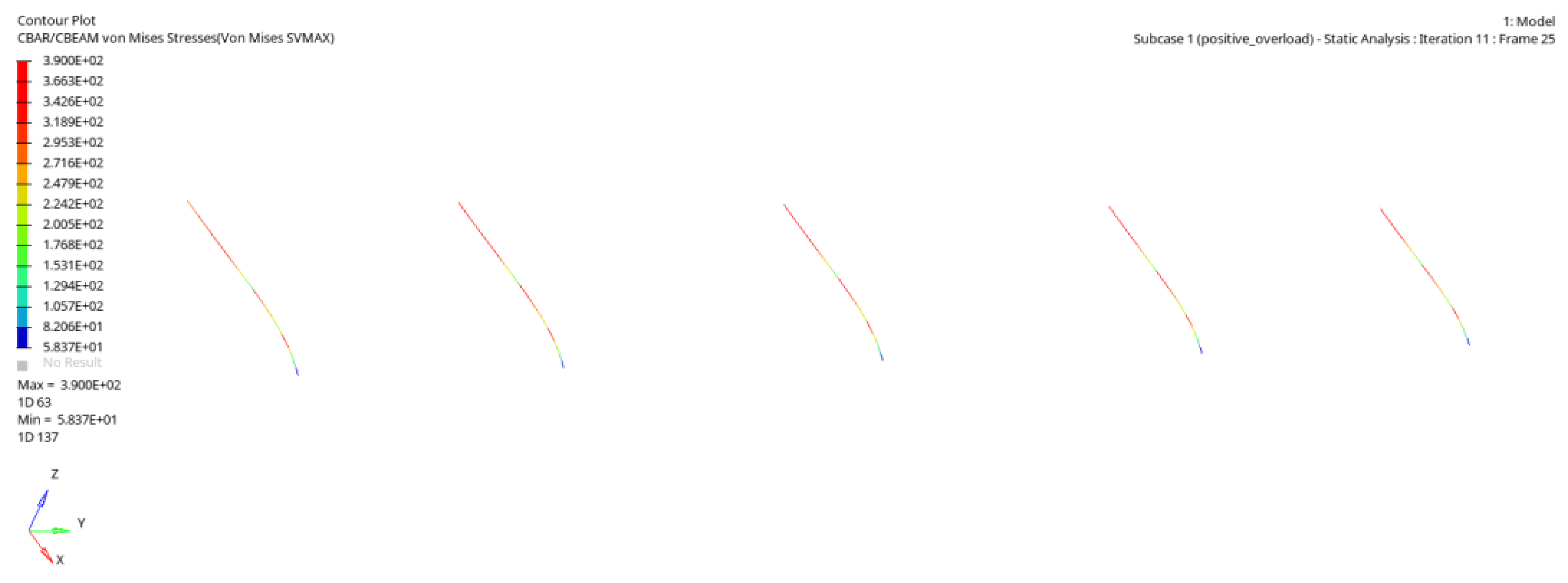
| displacement of curved beam end in Z-direction/mm | ≤9.21 | |
| stress of curved beam and planar disk/MPa | ≤390 |
| Variable | Initial Value | Optimization Result | Value Range |
|---|---|---|---|
| 0.0473 | 0.0473 | 0.0453~0.0493 | |
| 0.0266 | 0.0267 | 0.0246~0.0286 | |
| −0.0193 | −0.0193 | −0.0213~−0.0173 | |
| −0.0104 | −0.0104 | −0.0124~−0.0084 | |
| 18.67 | 18.74 |
| Variable | Initial Value | Optimization Result | Value Range |
|---|---|---|---|
| 0.0463 | 0.0462 | 0.0443~0.0483 | |
| 0.0192 | 0.0206 | 0.0172~0.0212 | |
| −0.0080 | −0.0064 | −0.0100~−0.0060 | |
| −0.0198 | −0.0194 | −0.0218~−0.0178 | |
| −0.0180 | −0.0180 | −0.0200~−0.0160 | |
| −0.0620 | −0.0637 | −0.0640~−0.0600 | |
| 1.4814 | 1.4997 |
| Variable | Initial Value | Optimization Result | Value Range |
|---|---|---|---|
| 0.0453 | 0.0455 | 0.0433~0.0473 | |
| 0.0192 | 0.0203 | 0.0172~0.0212 | |
| 0.0020 | 0.0024 | 0.0000~0.0040 | |
| −0.0201 | −0.0199 | −0.0221~−0.0181 | |
| −0.0160 | −0.0164 | −0.0180~−0.0140 | |
| −0.0200 | −0.0214 | −0.0220~−0.0180 | |
| 22.79 | 22.42 |
| Variable | Initial Value | Optimization Result | Value Range |
|---|---|---|---|
| 0.0493 | 0.0485 | 0.0473~0.0513 | |
| 0.0402 | 0.0387 | 0.0382~0.0422 | |
| 0.0390 | 0.0380 | 0.0370~0.0410 | |
| −0.0163 | −0.0162 | −0.0183~−0.0143 | |
| 0.0036 | 0.0023 | 0.0016~0.0056 | |
| 0.0460 | 0.0476 | 0.0440~0.0480 | |
| 0.7520 | 0.7742 |
| Variable | Initial Value | Optimization Result | Value Range |
|---|---|---|---|
| 1.2 | 1.4872 | 0.5~1.5 | |
| 0.5 | 0.5020 | 0.5~1.0 | |
| 0.08 | 0.0799 | 0.01~0.08 | |
| 1.0 | 1.5000 | 0.5~1.5 | |
| /MPa | 5.9191 | 2.8346 | |
| /MPa | 12,928 | 15,157 | |
| /με | 68,902 | 99,109 |
| Wing Structure | Design Variable | Initial Value | Optimal Value | Wing Structure | Design Variable | Initial Value | Optimal Value |
|---|---|---|---|---|---|---|---|
| upper skin | US11 | 2 mm | 0.993 mm | lower skin | LS11 | 2 mm | 0.644 mm |
| US12 | 1.5 mm | 0.978 mm | LS12 | 1.5 mm | 0.5 mm | ||
| US13 | 1.5 mm | 0.706 mm | LS13 | 1.5 mm | 0.5 mm | ||
| US21 | 1 mm | 0.5 mm | LS21 | 1 mm | 0.5 mm | ||
| US22 | 1 mm | 0.5 mm | LS22 | 1 mm | 0.5 mm | ||
| front spar web | FSW11 | 2 mm | 4.83 mm | rear spar web | BSW11 | 2 mm | 1.043 mm |
| FSW12 | 1.5 mm | 0.508 mm | BSW12 | 1.5 mm | 0.5 mm | ||
| FSW13 | 1.5 mm | 0.5 mm | BSW13 | 1.5 mm | 0.5 mm | ||
| FSW21 | 1 mm | 0.5 mm | BSW21 | 1 mm | 0.5 mm | ||
| FSW22 | 1 mm | 0.5 mm | BSW22 | 1 mm | 0.5 mm | ||
| front spar rod | FSR11 | 30 mm2 | 50 mm2 | rear spar rod | BSR11 | 30 mm2 | 50 mm2 |
| FSR12 | 25 mm2 | 44.07 mm2 | BSR12 | 25 mm2 | 10 mm2 | ||
| FSR13 | 25 mm2 | 10.3 mm2 | BSR13 | 25 mm2 | 10 mm2 | ||
| FSR21 | 20 mm2 | 10 mm2 | BSR21 | 20 mm2 | 10 mm2 | ||
| FSR22 | 20 mm2 | 10 mm2 | BSR22 | 20 mm2 | 10 mm2 | ||
| rib web | RW1 | 1 mm | 0.5 mm | rib rod | RR1 | 20 mm2 | 10 mm2 |
| RW2 | 1 mm | 0.5 mm | RR2 | 20 mm2 | 10 mm2 | ||
| SRW1 | 2 mm | 1.016 mm | SRR1 | 30 mm2 | 20 mm2 | ||
| wedge | JPUS | 1 mm | 0.5 mm | wedge | JPX1 JPX2 | 1 mm 1 mm | 0.997 mm 0.998 mm |
| JPLS | 1 mm | 0.5 mm | |||||
| JPY | 1 mm | 0.71 mm | |||||
| upper flexible skin | UHS1 | 3.5 mm | 2 mm | lower flexible skin | LHS1 | 3.5 mm | 2 mm |
| UHS2 | 3.5 mm | 2 mm | LHS2 | 3.5 mm | 2 mm | ||
| UHS3 | 2.5 mm | 2 mm | LHS3 | 2.5 mm | 2 mm | ||
| UHS4 | 1.5 mm | 1 mm | LHS4 | 1.5 mm | 1 mm | ||
| curved beam 1 | CB11 | 2 mm | 2.129 mm | disk on curved beam 1 | P11 P12 P13 | 3 mm 2 mm 1 mm | 0.5 mm 0.5 mm 0.537 mm |
| CB12 | 1.5 mm | 2.078 mm | |||||
| CB13 | 1 mm | 1.495 mm | |||||
| CB14 | 1 mm | 1.199 mm | |||||
| curved beam 2 | CB21 | 2 mm | 2.413 mm | disk on curved beam 2 | P21 P22 P23 | 3 mm 2 mm 1 mm | 0.5 mm 0.5 mm 0.539 mm |
| CB22 | 1.5 mm | 2.413 mm | |||||
| CB23 | 1 mm | 1.695 mm | |||||
| CB24 | 1 mm | 1.358 mm | |||||
| curved beam 3 | CB31 | 2 mm | 2.336 mm | disk on curved beam 3 | P31 P32 P33 | 3 mm 2 mm 1 mm | 0.5 mm 0.5 mm 0.541 mm |
| CB32 | 1.5 mm | 2.345 mm | |||||
| CB33 | 1 mm | 1.656 mm | |||||
| CB34 | 1 mm | 1.341 mm | |||||
| curved beam 4 | CB41 | 2 mm | 2.256 mm | disk on curved beam 4 | P41 P42 P43 | 3 mm 2 mm 1 mm | 0.5 mm 0.5 mm 0.544 mm |
| CB42 | 1.5 mm | 2.218 mm | |||||
| CB43 | 1 mm | 1.592 mm | |||||
| CB44 | 1 mm | 1.282 mm | |||||
| curved beam 5 | CB51 | 2 mm | 1.823 mm | disk on curved beam 5 | P51 P52 P53 | 3 mm 2 mm 1 mm | 0.5 mm 0.5 mm 0.548 mm |
| CB52 | 1.5 mm | 1.775 mm | |||||
| CB53 | 1 mm | 1.272 mm | |||||
| CB54 | 1 mm | 0.982 mm |
| Flight Condition | Performance Index | Optimization Result |
|---|---|---|
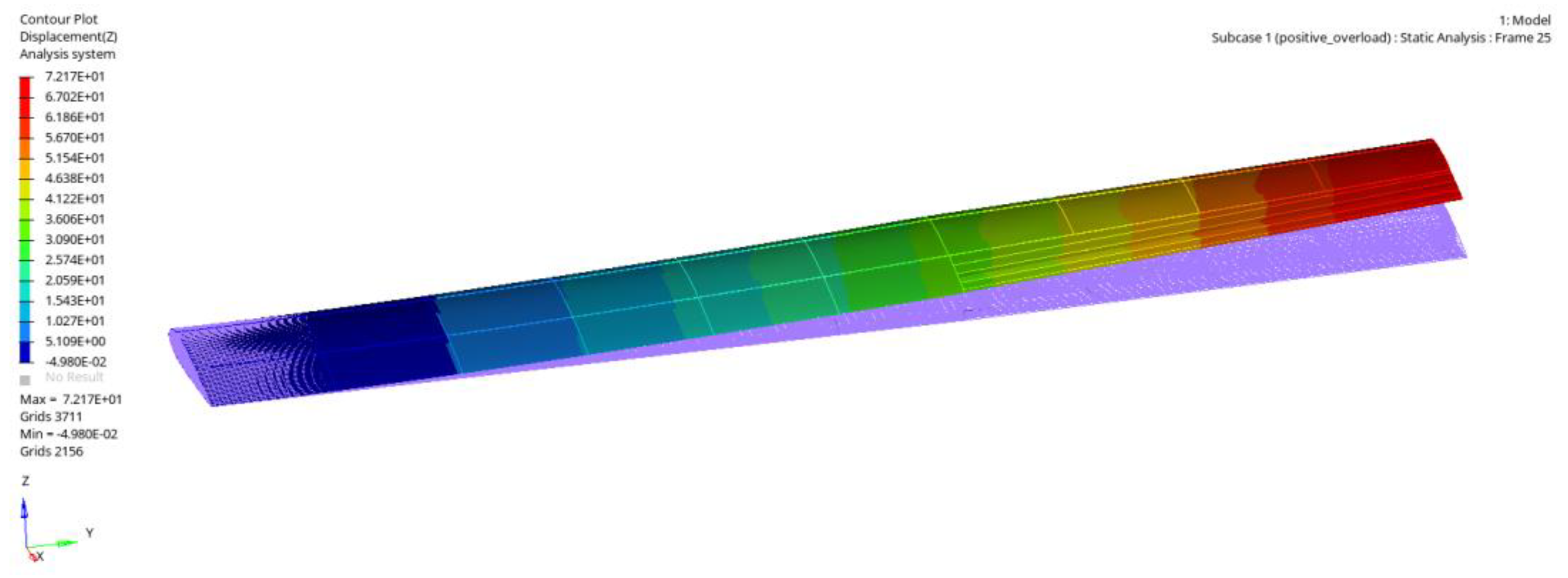
| condition A (0.3 Ma cruise) “+2.5 G” | displacement of wing tip in Z-direction/mm | 72.17 |
| stress of wing structure using duralumin/MPa | 387.7 | |
| strain of flexible skin at trailing edge of outer segment wing/με | 18,200 | |
| first-order instability factor | 0.80 | |
| condition D (take-off and landing) | displacement of wing tip in Z-direction/mm | 51.6 |
| stress of wing structure using duralumin/MPa | 256.4 | |
| strain of flexible skin at trailing edge of outer segment wing/με | 81,770 | |
| displacement of curved beam end in Z-direction/mm | 9.14 | |
| stress of curved beam and planar disk/MPa | 390 |
Disclaimer/Publisher’s Note: The statements, opinions and data contained in all publications are solely those of the individual author(s) and contributor(s) and not of MDPI and/or the editor(s). MDPI and/or the editor(s) disclaim responsibility for any injury to people or property resulting from any ideas, methods, instructions or products referred to in the content. |
© 2023 by the authors. Licensee MDPI, Basel, Switzerland. This article is an open access article distributed under the terms and conditions of the Creative Commons Attribution (CC BY) license (https://creativecommons.org/licenses/by/4.0/).
Share and Cite
Wang, Y.; Li, X.; Wu, T.; Yin, H. Multidisciplinary Design and Optimization of Variable Camber Wing with Non-Equal Chord. Aerospace 2023, 10, 336. https://doi.org/10.3390/aerospace10040336
Wang Y, Li X, Wu T, Yin H. Multidisciplinary Design and Optimization of Variable Camber Wing with Non-Equal Chord. Aerospace. 2023; 10(4):336. https://doi.org/10.3390/aerospace10040336
Chicago/Turabian StyleWang, Yu, Xiang Li, Tingjia Wu, and Hailian Yin. 2023. "Multidisciplinary Design and Optimization of Variable Camber Wing with Non-Equal Chord" Aerospace 10, no. 4: 336. https://doi.org/10.3390/aerospace10040336