Article

Unsteady Oblique Detonation Waves in a Tunnel Induced by Inflow Mach Number Variation

1
School of Aerospace Engineering, Beijing Institute of Technology, Beijing 100081, China
2
College of Engineering, Peking University, Beijing 100871, China
3
Advanced Jet Propulsion Innovation Center, Aero Engine Academy of China, Beijing 101300, China
4
Chongqing Innovation Center, Beijing Institute of Technology, Chongqing 401120, China
*
Author to whom correspondence should be addressed.
Aerospace 2023, 10(4), 330; https://doi.org/10.3390/aerospace10040330
Submission received: 26 February 2023 / Revised: 23 March 2023 / Accepted: 25 March 2023 / Published: 27 March 2023

Abstract

:
Oblique detonation waves (ODWs) have been investigated widely aiming at facilitating their application in hypersonic engines. However, there is a lack of research on unsteady ODWs which are unavoidable in the hypersonic air-breathing scenario. In this study, unsteady ODWs triggered by the variation of the inflow Mach number (M0) have been studied and the geometric model is a tunnel with an outward-deflection upper wall to mimic an engine outlet. Numerical results demonstrate that when M0 deviates from the designed state, two typical wave structures arise, featuring a Mach stem of detonation or a post-corner recirculation zone. A sudden change in M0 leads to the transition of these two structures, generating unsteady ODWs temporally with a multi-segment-complex wave surface caused by triple points. The wave structures near the corner have been analyzed in detail, revealing how the Mach stem and the recirculation zone evolve into each other. Furthermore, the effects of unsteady ODWs on hypersonic propulsion applications have been discussed, providing possible ways to suppress the Mach stem of detonation.

1. Introduction

The scramjet (supersonic combustion ramjet) has been extensively studied for air-breathing hypersonic aircraft [1], but it still presents significant challenges when operating at speeds up to Mach 10 or higher. The oblique detonation engine (ODE), a novel hypersonic propulsion system, has been proposed as an alternative to scramjet, due to its potential for pressure-gain combustion and high thermal efficiency [2,3,4,5]. Unlike scramjet, ODE uses an oblique detonation wave (ODW) to achieve fast heat release and high-specific impulse, making it attractive for high-speed flight [6,7]. However, the main challenge in ODE is to generate a steady ODW in hypersonic inflow, which has inspired several previous works on wave structure and steadiness.
Since the proposal of the concept of oblique detonation propulsion, researchers have conducted extensive studies on the morphology and structure of ODWs. Early works [5,8,9] generally treated ODW as an oblique shock wave (OSW) with instantaneous heat release, obtaining the relationship between inflow Mach number, wedge angle, and wave angle, and roughly grasping the standing window of oblique detonation combustion. Subsequent research [10,11,12,13] has obtained detailed wave system structures by considering detailed chemical-reaction processes, revealing the presence of an initial region, where the finite chemical reaction rate affects the intersection of reaction fronts and shock waves. As such, the effects of the initiation region on ODW structures have been widely explored in terms of OSW–ODW transition structures [14,15,16] and inflow-space inhomogeneity [17,18,19]. However, ODWs induced by an infinitely long wedge have limited practical value in the combustion organization inside ODE.
Additional research has investigated the ODE intersection with complicated combustion geometry. Recent studies [12,14,20,21,22] have examined ODWs in a semifinite wedge, revealing that an expansion wave induced by the outward-deflection upper wall could weaken the strength of ODW, decrease the angle of the ODW surface, and even cause the failure of the detonation wave. Wang et al. [23,24] developed a hypersonic tunnel with an outward deflection wall and found that there are two nonideal realistic flow structures. The first one arises when the corner is located upstream of an undisturbed surface, wherein the interaction between the expansion fan and ODW generates a recirculation zone post-corner, which couples with a gaseous wedge replacing the original expansion fan. The second structure occurs when a corner is positioned upstream of an unperturbed surface, resulting in the reflection of the ODW surface on the upper wall, thereby creating a Mach stem beneath the pre-corner upper wall.
The above-mentioned studies usually focus on oblique detonation waves under fixed inflow conditions and do not consider the effects of inflow variations [17,24,25,26,27]. By introducing the variable wedge angle [18,28,29] or inflow-density disturbance [30,31], unsteady ODWs are found to be complicated and have exhibited some new wave structures and complicated dynamics. However, the evolution of the ODW structure with unsteady inflow in confined spaces is currently unknown. We note that the variations, continuous or discrete, of the upstream state, have been considered by other authors in detonation research [26,32,33]. The sinusoidal disturbances are usually superimposed on a linear gradient to examine the effect of the disturbance amplitude and frequency [34,35], and the discrete disturbance is a simplification of situations where significant changes occur within a short period of time [36]. In this study, we aim to use ODEs to model the unsteady behavior of a scramjet engine undergoing sudden changes in inlet conditions. While gradual changes in inlet conditions may be more realistic, sudden changes provide a simpler and more efficient approach to addressing the problem at hand. It is worth mentioning that other authors have also explored the effects of both continuous and discrete disturbances on detonation researches [36,37,38].
In the paper, we introduce the model of confined space, which is a tunnel with an outward deflecting upper wall and a wedge on the lower wall. Then, we investigate the dynamics of ODWs structure resulting from the sudden change in the inflow Mach number. This study considers the practical situations when ODW reflects before or behind the corner with the inflow Mach number varying within a narrow range and has ascertained how the ODW structure evolves in the practical hypersonic combustors. The detailed dynamic evolution processes of ODWs are analyzed and discussed, giving further understanding on its response mechanisms in unsteady inflow with a suddenly variable Mach number.

2. Physical and Mathematical Model

A schematic of ODE with the computational domain is shown in Figure 1. The inflow is compressed by oblique shock, which is induced by the inlet, and then mixed with fuel from the supersonic injection. To focus on the unsteady features, the inhomogeneity from fuel–air mixing is not considered in this study, and the combustible mixtures with the inflow Mach number M0 are ignited via an ODW triggered by a solid wedge on the lower wall, as shown in Figure 1a. Different from most previous studies in free space, a channel with an outward deflection section or a turning corner is considered in this work, so the combustion product could expand and then provide greater thrust and impulse. In the ideal situation with a proper inflow, M0 [20,21], the ODW surface reflects on the turning corner, reaching the best performance of ODE. If M0 deviates slightly, the ODW could reflect before or behind the corner, as shown in Figure 1b. In this domain, H denotes the entrance height of the combustor; θ1 and θ2 are the wedge angle and the deflection angle of the upper wall, respectively; L and Lc are the length of the computational domain and the upper wall before the corner.
Many previous studies [7,8,9,10,39,40,41,42] have already proved that the two-dimensional compressible Euler equations with a two-step induction-reaction model can effectively solve the ODW in a confined combustor. For the chemical reaction, the induction reaction index ξ varying from one to zero and the heat release index λ varying from zero to one are used to control the process of reaction. The transport equations with a reaction source can be expressed as [43]:
( ρ ξ ) t + ( ρ u ξ ) x + ( ρ v ξ ) y = H ( 1 ξ ) ρ k I exp [ E I ( 1 T S 1 T ) ]
( ρ λ ) t + ( ρ u λ ) x + ( ρ v λ ) y = [ 1 H ( 1 ξ ) ] ρ ( 1 λ ) k R exp [ E R T ]
in which the Heaviside step function H(1 − ξ) is given as
H ( 1 ξ ) = { 1 , ξ 1 0 , ξ > 1
EI and ER represent the activation energy of induction and heat release, respectively. Two constants, kI and kR, are used to control the chemical reaction rates in the induction and exothermic zones. In this study, kR is set to be 1.0, and kI = −uvn, for which uvn is the flow velocity behind the leading shock wave in the Zeldovich–von Neumann–Döring (ZND) detonation wave in a shock-fixed coordinate system. The variables, p, ρ, T, u, and v are the pressure, density, temperature, x-direction velocity, and y direction velocity, respectively. All of them are dimensionless with reference to the free flow state (in which, the tilde~denotes the original dimension quantity, and subscript 0 denotes the reference quantity of the free flow):
p = p ˜ p 0 , ρ = ρ ˜ ρ 0 , T = T ˜ T 0 , u = u ˜ R T 0 , v = v ˜ R T 0
The main parameters in this study are set to be Q = 10, γ = 1.3, EI = 3.0TS, and ER = 1.0TS, where TS is the postshock temperature of Chapman–Jouguet (CJ) detonation and Q is the amount of chemical heat release. The induction region width ΔI of the one-dimensional ZND detonation wave is taken as unit length. The flow time is dimensionless with the sound velocity of the wavefront reactants, i.e., t = ΔI/c0, where c0 is the initial sound velocity of the reactants. The selection of these parameters refers to the hydrogen–air mixture entering the ODE combustor while operating at a high altitude. Compared with previous studies [22,23,31], Q and EI decrease significantly to mimic the inflow with low density and high temperature, deriving from the high altitude and inlet compression, respectively.
The governing equations are solved using the AUSMPW+ approach with a third-order MUSCL scheme. The third-order Runge–Kutta algorithm is chosen as the time-discretization scheme in these simulations [23,24,31]. The geometric parameters, as shown in Figure 1b, are set to be H1 = 150, Lc = 185, L = 320, θ1 = 20°, and θ2 = 55°, among which Lc is critical to obtain the typical flow-field structures. It is worth noting that the induction region width ΔI is the characteristic length scale of the ZND detonation wave and is also taken as the unit length. In this study, the length of the calculated domain is dimensionless by ΔI. As for the boundary conditions, the left entrance is modeled as a supersonic inflow boundary condition in which the flow parameters are constant; the right dashed lines correspond to the existence of the combustor and are set to be outflow boundaries, whose boundary parameters are extrapolated from the interior; the upper walls and lower wedge are characterized as slip boundaries.

3. Results and Discussion

3.1. Basic Structures of Oblique Detonation and Resolution Study

The main work in this paper is to calculate the wave system in the combustor, and the parameter of the combustor inlet is compressed through the intake. Given Q = 10 and γ = 1.3, the Mach number of a CJ detonation is approximately 3.5, which is lower than the stoichiometric hydrogen–air mixtures at sea level. Considering that the ODE-based hypersonic aircraft is suitable for flight at a Mach number above 10, we assume that the Mach number of the combustor inlet is half of the flight Mach number after forebody compression, which is set to be 5.5 to 6.0. As mentioned above, Lc is a critical parameter, which is chosen according to M0 in this study. The basic simulations of ODWs without considering the upper wall at M0 5.5 and 6.0 are performed to get the positions of ideal ODW surfaces. Finally, the Lc is chosen as 185, which is between these two positions. It means that there is a certain M0 between 5.5 and 6.0, at which the ODW reflects on the corner, and the ODE operates at the designed state.
Using the calibrated geometric parameters, two steady ODW structures depending on M0 are shown in Figure 2. It could be seen that the OSW induced by the lower wall turns into ODW near the position x = 40~60 gradually. The ODW surface extends downstream with the same smooth OSW–ODW transition, however, the ODW surface angle is affected by M0 obviously. More importantly, the ODW surfaces reflect on different positions of the upper wall, before or behind the corner, resulting in different wave structures. Generally speaking, due to the different M0, the ODW could lead to two nonideal wave structures in a confined space whose geometric parameters are fixed.
These two typical wave structures are the basis of further study on unsteady ODWs, so their schematics are plotted in Figure 3. With a low M0 5.5, the ODW surface reflects before the corner, leading to the Mach reflection and a Mach stem of detonation, as shown in Figure 3a. The Mach reflection changes the whole wave system, leading to a reflected shock wave, the second slip line, et al. On the other hand, the ODW surface reflects behind the corner with a high M0 6.0, leading to an evidently different wave configuration. As shown in Figure 2b and Figure 3b, a recirculation zone forms behind the outward-turning corner, attributing the ODW decoupling influenced by the expansion wave. Despite different parameters of the chemical-reaction model, these wave structures have been observed in previous studies [24], though only steady structures with a fixed M0 were investigated.
To examine the effects of grid scale on the simulation results, the resolution verification has been carried out by refining the mesh in the directions of x and y, as shown in Figure 4. The temperature contours of ODW with different scales are shown in Figure 4a. Three temperature curves nearly overlap with each other and there are no significant differences in the overall flow structures. Furthermore, the temperature and pressure along the line y = 100 are also compared quantitatively, as shown in Figure 4b. Three groups of grid numbers, i.e., 3200 × 1500, 2600 × 750, and 2000 × 500, are used to solve the ODW flow structure. Based on the 3200 × 1500 scales, the maximum deviation of temperature and pressure occurs near the shock front, which is still less than 5%. For most flow fields, the deviation of state parameters is less than 1%. The quantitative evaluation of the temperature–pressure profiles illustrates almost identical distributions. Furthermore, the wave systems near the wall are the main concern of this study, and the grid near the wall surface has been refined locally to reach as low as 0.06. The cases above have shown that these three groups of grid scales can resolve the ODW structure details, such as reflected shocks, expansion waves, and recirculation zones. Therefore, we believe the grid numbers with 2600 × 750 nodes are sufficient for the present research and will be used in the following simulations.

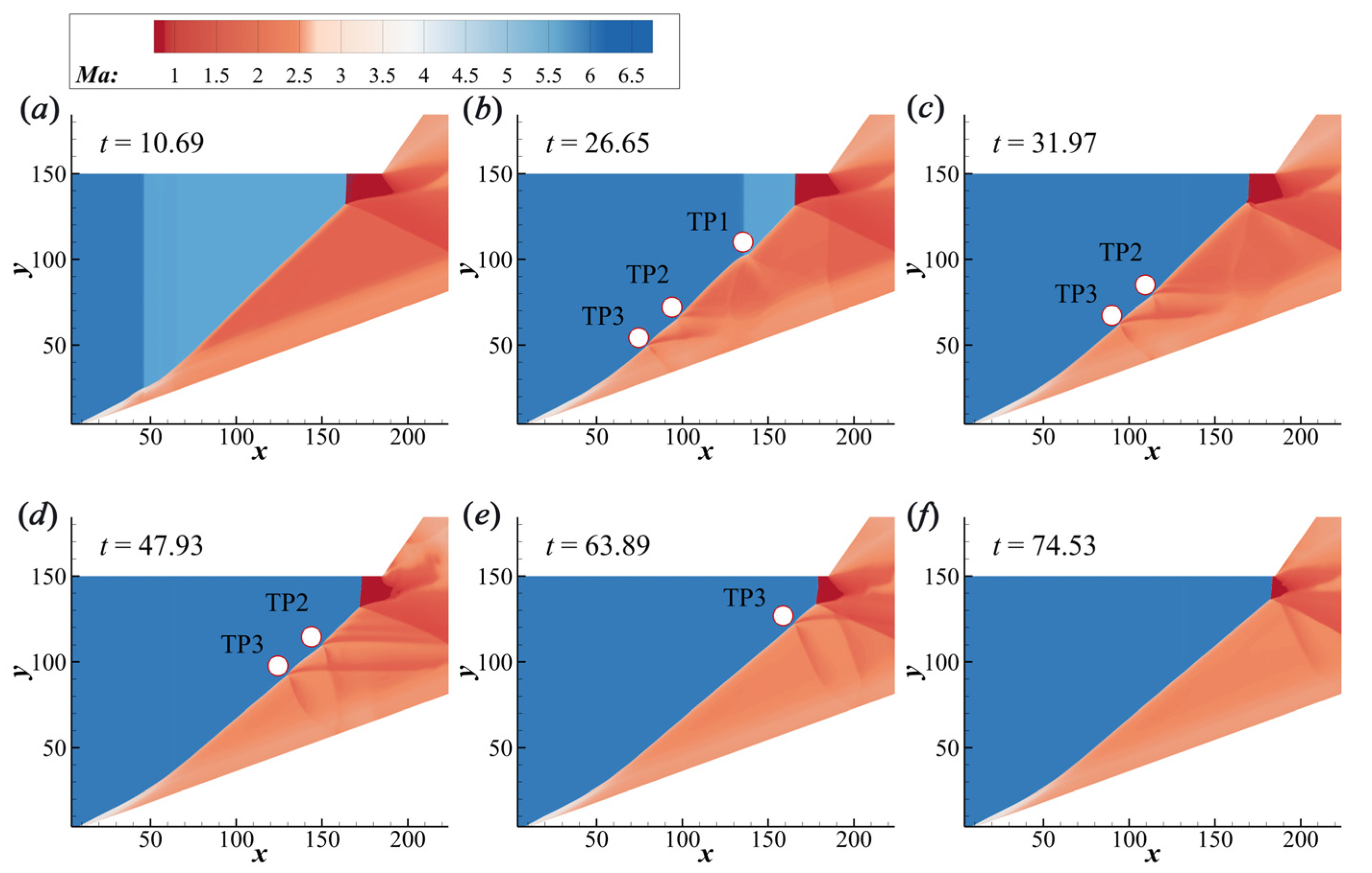
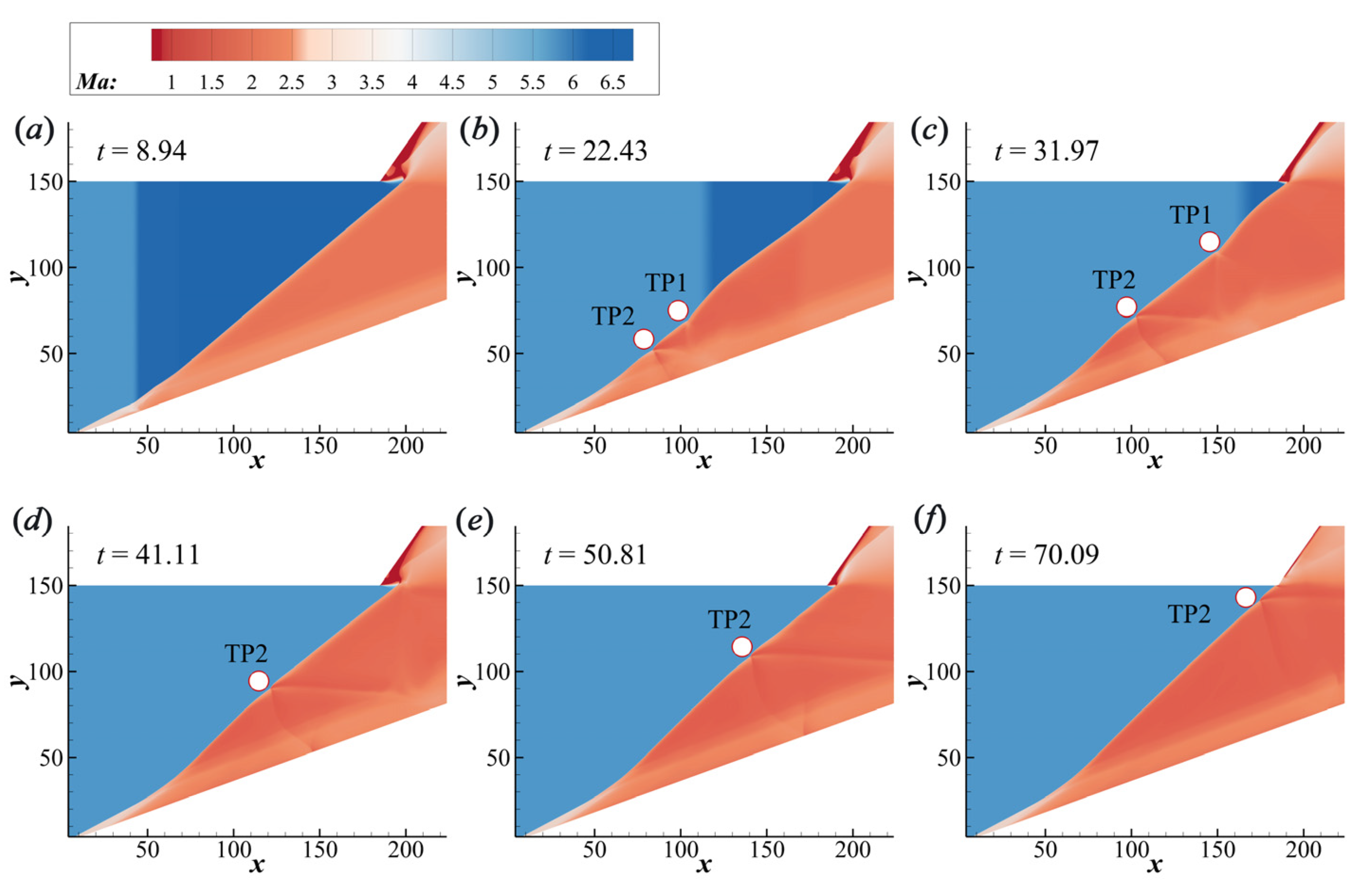
3.2. Surface Evolution in the Structural Variation

The main focus of this paper is to simulate the unsteady ODWs in transition processes by changing M0 based on the two steady structures. The structural variation of increasing M0 is shown in Figure 5. Initially, an ODW with M0 5.5 exists, whose structure features a Mach stem of detonation. Then, the inflow M0 of the left boundary changes from 5.5 to 6.0, and the flow time is reset to be zero simultaneously. It is observed that a sudden increase of M0 leads to the distortion of the upstream ODW surface, as shown in Figure 5a. Subsequently, triple points (TPs) form on the wave surface and propagate downstream, resulting in a multisegment complex wave surface, as shown in Figure 5b. TP1 is a left-running triple point facing downstream, and the other two belong to right-running triple points [41,42]. In fact, it could be seen that TP1 originated from the contact surface of velocity discontinuity, while TP2 and TP3 are from the self adjustment of the wave surface. Finally, these TPs move downstream and merge into the Mach stem. It should be noted that the contact surface of inflow velocity reaches the Mach stem before t = 31.97 (Figure 5c), however, TP2 and TP3 travel slowly and persist for a long time thereafter. This demonstrates that the ODW surface could self adjust to fit the increasing inflow M0 to some extent, which is achieved by triple points behind the contact surface.
To analyze the ODW surface evolution, the shock-front positions along different lines y = 60, 75, and 90 are recorded as a function of time, as shown in Figure 6. The shock-front location is defined by the local pressure in which the pressure value reaches twice the free inflow. The wave-front position moves downstream, however, it is not monotonous for the appearance of triple points (TPs). Combining the flow fields (Figure 5), it is obvious that the TP1 leads to the first peak of these curves, making the wave front move quickly toward the upstream. On the curves, the effects of TP2 and TP3 on the wave surface are weaker, because TP1 is from the variation of velocity and is accompanied by the discontinuous velocity contact, while TP2 and TP3 are induced to adjust the ODW surface. When comparing the three curves in Figure 6, we found that the velocities of TP2 and TP3 traveling downstream are close, and smaller than the velocity of TP1, so the downstream surface needs a longer time to relax.
The structural variation of decreasing M0 is shown in Figure 7. Initially, an ODW with M0 6.0 exists, whose structure features a postcorner recirculation zone. Then, the inflow M0 of the left boundary changes from 6.0 to 5.5, and the flow time is reset to zero simultaneously. Similarly, M0 variation also leads to a distortional wave surface, generating two TPs. TP1 also originated from the interaction of the velocity contact and detonation front, however, the movement of the resulting TP1 is slightly slower than the contact surface. Notably, when the contact surface goes through the whole flow fields, TP2 still exists on the surface, which has a slow-moving process to adjust the wave surface. During this process, the recirculation zone becomes smaller but does not disappear until t = 70.09 (Figure 7f).
Obviously, the structural variation is different in the two processes of increasing or decreasing M0. To analyze the procedure of decreasing M0, the shock-front position along different lines is also recorded as a function of time, as shown in Figure 8. The wave-front position moves upstream, while TPs formed in this process are distinguished from Figure 6 in strength and function. Compared with Figure 6, the TP1 in Figure 8 leads to the first peak of these lines, causing the wave surface to suddenly move downstream, which prevented the whole wave surface from moving upstream. For these two processes, it is obvious that TPs formed on the wave surface both affect the movement of the detonation wave. The difference is that the action of the TPs is consistent with the direction of the wave surface movement for increasing M0 while decreasing M0 leads to an opposite result.
A variation in inflow Mach number triggers the mutual transition of two typical ODW configurations. Notably, increasing or decreasing M0 can both lead to structural variation, resulting in a multisegment-complex wave surface at the initial stage. For these two processes, the contact surface of inflow velocity could go through the whole flow fields quickly, while the detonation front would still be in a self-adjusting state and the original near-corner structures do not disappear immediately, demonstrating that the formation of the new structures mainly depends on the self-adjusting characteristic of the detonation wave.

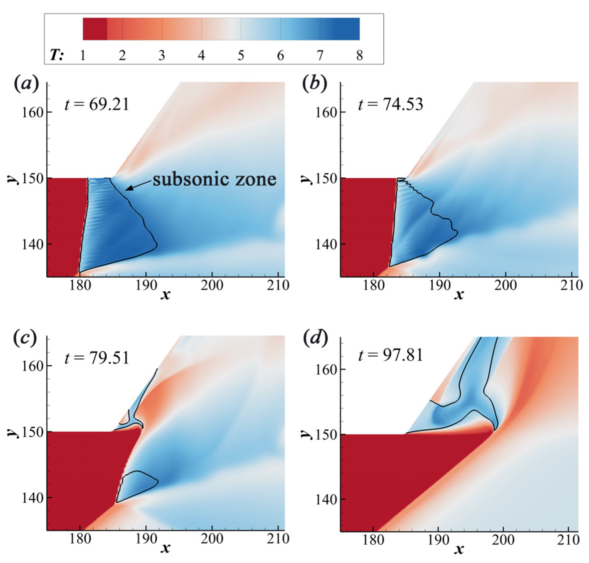
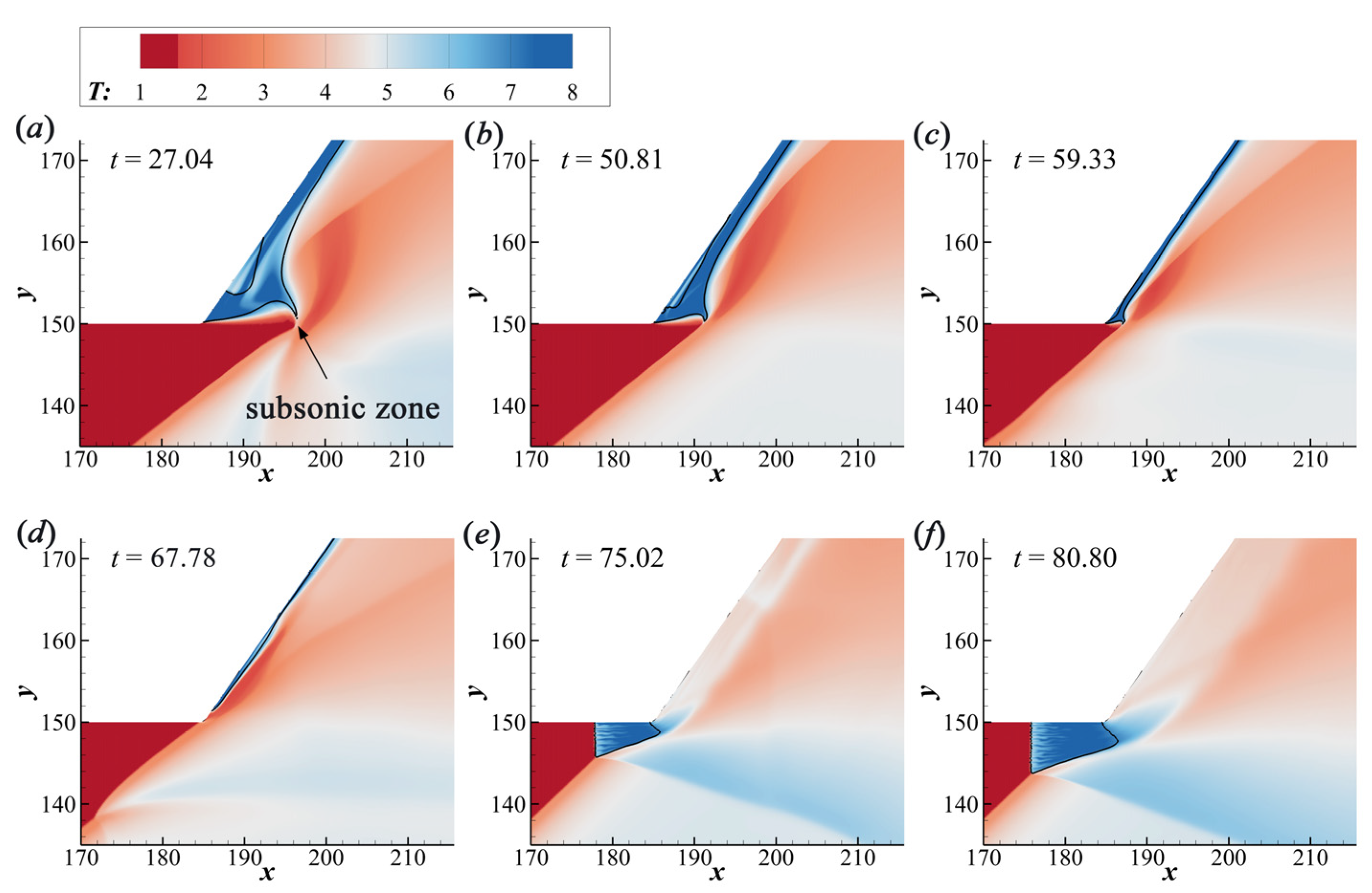
3.3. Discussion on the Near-Corner Structures

The above results demonstrate that the variation of inflow M0 (increasing or decreasing) in steady cases involves triple points on ODWs structure. The triple points are critical to adjust the upstream and downstream of wave surfaces, but they only influence the development of the ODWs structure at the early stage. The other important phenomenon to be noted in this study is that unsteady ODWs are also concerned with the transition between the Mach stem of detonation and the postcorner recirculation zone which is named as the near-corner structures here.
In this section, we investigate the formation of the recirculation zone during the process of the increasing M0. Figure 9 shows the evolution processes of local temperature fields of ODW near the corner, with the black curve denoting the sonic regions. When the M0 increases from 5.5 to 6.0, the Mach stem moves downstream, finally inducing a recirculation zone. It is observed that the Mach stem becomes oblique and the subsonic zone shrinks, splitting into two small parts in Figure 9c. Ultimately, the lower subsonic zone disappears slowly due to the fact that the surface angle of ODW increases continuously, whereas the upper subsonic region is gradually building up and a relatively large recirculation zone arises here. The recirculation zone has been observed previously [23], whose formation is attributed to the reversed pressure gradient downstream. The low-temperature region could be observed in Figure 9c, enlarging together with the upper recirculation zone. In general, this work not only supports the formation mechanism of the recirculation zone proposed before but demonstrates that the original subsonic zone might evolve from a Mach stem of detonation and then grows from one extremely small point.
The local flow-wave systems of ODW, with a sudden velocity decrease, are plotted in Figure 10. When the velocity discontinuity goes through the corner, the overall ODW moves upstream and the recirculation zone disappears gradually. It can be observed that the recirculation zone is compressed heavily by the ODW front, thus becoming a slender subsonic zone that finally disappears. This process is notably different from the results shown in Figure 9. These results demonstrate that the formation and disappearance of the recirculation zone have their separate paths. The former originated from the splitting of the Mach stem and expands as the downstream movement of the ODW front, while the latter is squeezed by the ODW front and disappears, whose subsonic zone decreases sharply in a relatively short time, as shown in Figure 10b,c.
The transformations between the two typical flow structures have shown obvious differences, so the formation and disappearance of the recirculation zone are irreversible. To further analyze the dynamic process, the shock position near the upper wall as a function of time is plotted in Figure 11. The solid and dashed lines are based on the cases with increasing and decreasing M0, respectively, whereas the red squares denote the state when the wave front reaches the turning point. It is observed that when M0 increases from 5.5 to 6.0, the shock front quickly moves downstream and becomes steady within a short time. In contrast, the decreasing M0 results in an extremely long transition time, which should be attributed to the slow-moving Mach stem. Even though the final near-corner structures in unsteady inflow, the M0 remains the same with that steady flow. These processes exhibit that different wave dynamics could be involved with different spatial and temporal characteristics.
These results reveal the dynamic of ODWs structures when inflow M0 varies, which concerns with different subsonic zones. The subsonic zones are unavailable from the viewpoint of the ODE application since the ODE is designed to be supersonic in the whole flow tunnel. These results provide a physical description of ODW dynamics in a confined combustor and deepen our understanding of the ODW combustor design under the velocity variation conditions. When M0 is increasing, the flow structures mainly include three major steps, i.e., from one subsonic zone (Mach stem) to two subsonic zones (recirculation zone and strong oblique detonation) and finally to one subsonic zone (large recirculation zone). Considering that the Mach stem is equivalent to a normal detonation wave with a high M0, the total pressure loss will be very high, so increasing M0 could improve the impulse performance. On the contrary, the Mach stem forms accompanied by the decreasing M0, so the impulse performance becomes worse. Based on the present work, we found that the formation and moving of the Mach stem is a slow process, so it is possible to suppress it. For example, the Mach stem could be eliminated by adjusting the position of the upper-wall turning point, which could be achieved using a geometric variable device. For further consideration, the leaking slot located on the upper wall before the turning point could also be an option, which could weaken the Mach stem theoretically.

4. Conclusions

This study simulated the unsteady ODWs aroused by the inflow M0 variation and ascertained the evolution processes of the ODW structure in a confined combustor, which is more in resemblance to the practical geometric model of the engine and the unsteady flow at different hypersonic flight conditions. The results demonstrate that when M0 deviates from the designed state, two typical wave structures arise, featuring a Mach stem of detonation or a postcorner recirculation zone. Notably, decreasing or increasing M0 can lead to the mutual transitions of these two typical structures, and a multisegment complex-wave surface caused by triple points appeared in both of the two processes. Meanwhile, the TP1 originated from the interaction of the velocity and detonation front going through the whole flow fields quickly, and the other TPs existing on the ODW surface move slowly to adjust the wave surface, demonstrating that the formation of new structures mainly depends on the self-adjusting characteristic of the detonation wave. The wave structures near the corner have been analyzed in detail, revealing that the formation and disappearance of the recirculation zone have their separate paths. The former originated from the splitting of the Mach stem and expands into a large one quickly, while the latter is squeezed by the ODW front and evolves into a Mach stem with a slow-moving process, demonstrating that different wave dynamics are involved in different spatial and temporal characteristics. Finally, this study discussed the effects of unsteady ODWs on propulsive application and illustrated that the Mach stem forming and moving in a slow process could be suppressed, which deepens our understanding of the ODW combustor design under velocity-variation conditions.

Author Contributions

Conceptualization, P.Y. and S.N.; Methodology, P.Y. and H.T.; Software, P.Y. and S.N.; Validation, P.Y., S.N. and K.W.; Formal Analysis, P.Y., S.N. and H.T.; Investigation, S.N.; Resources, P.Y., H.T. and K.W.; Writing—original draft preparation, P.Y., S.N., H.T. and K.W.; Writing—Review & Editing, P.Y., S.N., H.T. and K.W.; Funding Acquisition, P.Y., K.W. and H.T. All authors have read and agreed to the published version of the manuscript.

Funding

This research was funded by the National Natural Science Foundation of China, grant number 12202014 and 12002041; the Advanced Jet Propulsion Innovation Center, Aero Engine Academy of China, grant number HKCX2022-01-018; and the Postdoctoral Science Foundation of China, grant number 2021M700222.

Data Availability Statement

All data used during the study appear in the submitted article.

Acknowledgments

We thank the timely help given by Hoi Dick Ng in analyzing the large number of samples.

Conflicts of Interest

The authors declare no conflict of interest.

References

  1. Urzay, J. Supersonic Combustion in Air-Breathing Propulsion Systems for Hypersonic Flight. Annu. Rev. Fluid Mech. 2018, 50, 593–627. [Google Scholar] [CrossRef]
  2. Valorani, M.; Di Giacinto, M.; Buongiorno, C. Performance Prediction for Oblique Detonation Wave Engines (Odwe). Acta Astronautica 2001, 48, 211–228. [Google Scholar] [CrossRef]
  3. Chan, J.; Sislian, J.P.; Alexander, D. Numerically Simulated Comparative Performance of a Scramjet and Shcramjet at Mach 11. J. Propuls. Power 2010, 26, 1125–1134. [Google Scholar] [CrossRef] [Green Version]
  4. Alexander, D.C.; Sislian, J.P.; Parent, B. Hypervelocity Fuel/Air Mixing in Mixed-Compression Inlets of Shcramjets. AIAA J. 2006, 44, 2145–2155. [Google Scholar] [CrossRef]
  5. Xu, Z.; Dong, G.; Pan, Z.; Gui, M. Standing Window of Oblique Detonation with Pathological Behaviour. Chin. J. Aeronaut. 2021, 34, 496–503. [Google Scholar] [CrossRef]
  6. Sislian, J.P.; Martens, R.P.; Schwartzentruber, T.E.; Parent, B. Numerical Simulation of a Real Shcramjet Flowfield. J. Propuls. Power 2006, 22, 1039–1048. [Google Scholar] [CrossRef]
  7. Rosato, D.A.; Thornton, M.; Sosa, J.; Bachman, C.; Goodwin, G.B.; Ahmed, K.A. Stabilized Detonation for Hypersonic Propulsion. Proc. Natl. Acad. Sci. USA 2021, 118, e2102244118. [Google Scholar] [CrossRef]
  8. Powers, J.M.; Gonthier, K.A. Reaction Zone Structure for Strong, Weak Overdriven, and Weak Underdriven Oblique Detonations. Phys. Fluids A Fluid Dyn. 1992, 4, 2082–2089. [Google Scholar] [CrossRef]
  9. Li, C.; Kailasanath, K.; Oran, E.S. Detonation Structures behind Oblique Shocks. Phys. Fluids 1994, 6, 1600–1611. [Google Scholar] [CrossRef]
  10. Choi, J.-Y.; Kim, D.-W.; Jeung, I.-S.; Ma, F.; Yang, V. Cell-like Structure of Unstable Oblique Detonation Wave from High-Resolution Numerical Simulation. Proc. Combust. Inst. 2007, 31, 2473–2480. [Google Scholar] [CrossRef]
  11. Verreault, J.; Higgins, A.J. Initiation of Detonation by Conical Projectiles. Proc. Combust. Inst. 2011, 33, 2311–2318. [Google Scholar] [CrossRef]
  12. Gao, Y.; Li, H.; Xiang, G.; Peng, S. Initiation Characteristics of Oblique Detonation Waves from a Finite Wedge under Argon Dilution. Chin. J. Aeronaut. 2021, 34, 81–90. [Google Scholar] [CrossRef]
  13. Zhu, Y.-J.; Dong, G.; Liu, Y.-X.; Fan, B.-C.; Jiang, H. Effect of Chemical Reactivity on the Detonation Initiation in Shock Accelerated Flow in a Confined Space. Acta Mech. Sin. 2013, 29, 54–61. [Google Scholar] [CrossRef]
  14. Verreault, J.; Higgins, A.J.; Stowe, R.A. Formation and Structure of Steady Oblique and Conical Detonation Waves. AIAA J. 2012, 50, 1766–1772. [Google Scholar] [CrossRef]
  15. Miao, S.; Zhou, J.; Liu, S.; Cai, X. Formation Mechanisms and Characteristics of Transition Patterns in Oblique Detonations. Acta Astronaut. 2018, 142, 121–129. [Google Scholar] [CrossRef]
  16. Zhang, Y.; Fang, Y.; Ng, H.D.; Teng, H. Numerical Investigation on the Initiation of Oblique Detonation Waves in Stoichiometric Acetylene–Oxygen Mixtures with High Argon Dilution. Combust. Flame 2019, 204, 391–396. [Google Scholar] [CrossRef]
  17. Iwata, K.; Nakaya, S.; Tsue, M. Wedge-Stabilized Oblique Detonation in an Inhomogeneous Hydrogen–Air Mixture. Proc. Combust. Inst. 2017, 36, 2761–2769. [Google Scholar] [CrossRef]
  18. Fang, Y.; Hu, Z.; Teng, H.; Jiang, Z.; Ng, H.D. Numerical Study of Inflow Equivalence Ratio Inhomogeneity on Oblique Detonation Formation in Hydrogen–Air Mixtures. Aerosp. Sci. Technol. 2017, 71, 256–263. [Google Scholar] [CrossRef] [Green Version]
  19. Li, J.; Pan, J.; Jiang, C.; Ni, J.; Pan, Z.; Otchere, P. Effect of Hydrogen Addition on the Detonation Performances of Methane/Oxygen at Different Equivalence Ratios. Int. J. Hydrogen Energy 2019, 44, 27974–27983. [Google Scholar] [CrossRef]
  20. Papalexandris, M.V. A Numerical Study of Wedge-Induced Detonations. Combust. Flame 2000, 120, 526–538. [Google Scholar] [CrossRef]
  21. Choi, J.-Y.; Shin, E.J.-R.; Jeung, I.-S. Unstable Combustion Induced by Oblique Shock Waves at the Non-Attaching Condition of the Oblique Detonation Wave. Proc. Combust. Inst. 2009, 32, 2387–2396. [Google Scholar] [CrossRef]
  22. Xiang, G.; Zhang, Y.; Gao, X.; Li, H.; Huang, X. Oblique Detonation Waves Induced by Two Symmetrical Wedges in Hydrogen-Air Mixtures. Fuel 2021, 295, 120615. [Google Scholar] [CrossRef]
  23. Wang, K.; Teng, H.; Yang, P.; Ng, H.D. Numerical Investigation of Flow Structures Resulting from the Interaction between an Oblique Detonation Wave and an Upper Expansion Corner. J. Fluid Mech. 2020, 903, A28. [Google Scholar] [CrossRef]
  24. Wang, K.; Yang, P.; Teng, H. Steadiness of Wave Complex Induced by Oblique Detonation Wave Reflection before an Expansion Corner. Aerosp. Sci. Technol. 2021, 112, 106592. [Google Scholar] [CrossRef]
  25. Shi, X.; Zhu, Y.; Yang, J.; Luo, X. Mach Stem Deformation in Pseudo-Steady Shock Wave Reflections. J. Fluid Mech. 2019, 861, 407–421. [Google Scholar] [CrossRef]
  26. Wang, H.; Zhai, Z.; Luo, X.; Yang, J.; Lu, X. A Specially Curved Wedge for Eliminating Wedge Angle Effect in Unsteady Shock Reflection. Phys. Fluids 2017, 29, 086103. [Google Scholar] [CrossRef]
  27. Han, Y.; Shen, C.; Du, Z.; Tang, H. Numerical Study of the Induced Shock on the Mixing Augmentation of Hydrogen Counter-Flow Jet in the Supersonic Flow. Aerospace 2022, 9, 506. [Google Scholar] [CrossRef]
  28. Liu, Y.; Wang, L.; Xiao, B.; Yan, Z.; Wang, C. Hysteresis Phenomenon of the Oblique Detonation Wave. Combust. Flame 2018, 192, 170–179. [Google Scholar] [CrossRef]
  29. Qin, Q.; Zhang, X. Study on the Transition Patterns of the Oblique Detonation Wave with Varying Temperature of the Hydrogen-Air Mixture. Fuel 2020, 274, 117827. [Google Scholar] [CrossRef]
  30. Yang, P.; Ng, H.D.; Teng, H. Numerical Study of Wedge-Induced Oblique Detonations in Unsteady Flow. J. Fluid Mech. 2019, 876, 264–287. [Google Scholar] [CrossRef] [Green Version]
  31. Yang, P.; Ng, H.D.; Teng, H. Unsteady Dynamics of Wedge-Induced Oblique Detonations under Periodic Inflows. Phys. Fluids 2021, 33, 016107. [Google Scholar] [CrossRef]
  32. Mi, X.; Higgins, A.J.; Goroshin, S.; Bergthorson, J.M. The Influence of Spatial Discreteness on the Thermo-Diffusive Instability of Flame Propagation with Infinite Lewis Number. Proc. Combust. Inst. 2017, 36, 2359–2366. [Google Scholar] [CrossRef] [Green Version]
  33. Kasimov, A.R. Reactive Burgers Model for Detonation Propagation in a Non-Uniform Medium. Proc. Combust. Inst. 2021, 8, 3725–3732. [Google Scholar] [CrossRef]
  34. Kim, M. Nonlinear Dynamics and Chaos Regularization of One-Dimensional Pulsating Detonations with Small Sinusoidal Density Perturbations. Proc. Combust. Inst. 2021, 8, 3701–3708. [Google Scholar] [CrossRef]
  35. Gui, M.-Y.; Fan, B.-C.; Dong, G. Periodic Oscillation and Fine Structure of Wedge-Induced Oblique Detonation Waves. Acta Mech. Sin. 2011, 27, 922–928. [Google Scholar] [CrossRef]
  36. Ning, J.; Chen, D.; Li, J. Numerical Studies on Propagation Mechanisms of Gaseous Detonations in the Inhomogeneous Medium. Appl. Sci. 2020, 13, 4585. [Google Scholar] [CrossRef]
  37. Xi, X.; Teng, H.; Chen, Z.; Yang, P. Effects of Longitudinal Disturbances on Two-Dimensional Detonation Waves. Phys. Rev. Fluids 2022, 7, 043201. [Google Scholar] [CrossRef]
  38. Niu, S.; Yang, P.; Yang, Y.; Teng, H. Numerical study of the effect of a sudden change in inflow velocity on the stability of an oblique detonation reflected wave system. Sci. Sin.-Phys. Mech. Astron. 2023, 53, 234711. [Google Scholar] [CrossRef]
  39. Teng, H.; Bian, J.; Zhou, L.; Zhang, Y. A Numerical Investigation of Oblique Detonation Waves in Hydrogen-Air Mixtures at Low Mach Numbers. Int. J. Hydrogen Energy 2021, 46, 10984–10994. [Google Scholar] [CrossRef]
  40. Da Silva, L.F.; Deshaies, B. Stabilization of an Oblique Detonation Wave by a Wedge: A Parametric Numerical Study. Combust. Flame 2000, 121, 152–166. [Google Scholar] [CrossRef]
  41. Zhang, Y.; Yang, P.; Teng, H.; Ng, H.D.; Wen, C. Transition Between Different Initiation Structures of Wedge-Induced Oblique Detonations. AIAA J. 2018, 56, 4016–4023. [Google Scholar] [CrossRef]
  42. Yan, C.; Teng, H.H.; Mi, X.C.; Ng, H.D. The Effect of Chemical Reactivity on the Formation of Gaseous Oblique Detonation Waves. Aerospace 2019, 6, 62. [Google Scholar] [CrossRef] [Green Version]
  43. Ng, H.D.; Radulescu, M.I.; Higgins, A.J.; Nikiforakis, N.; Lee, J.H.S. Numerical Investigation of the Instability for One-Dimensional Chapman–Jouguet Detonations with Chain-Branching Kinetics. Combust. Theory Model. 2005, 9, 385–401. [Google Scholar] [CrossRef]
Figure 1. (a) Schematics of the oblique detonation engine and (b) the computational model of the combustor.
Aerospace 10 00330 g001
Figure 2. Temperature fields for ODWs in the case of (a) M0 = 5.5; (b) M0 = 6.0. Black curves represent streamlines.
Aerospace 10 00330 g002
Figure 3. Two typical wave structures: (a) with a Mach stem of detonation, (b) with a postcorner recirculation zone.
Aerospace 10 00330 g003
Figure 4. Temperature fields (a) and pressure/temperature profiles (b) along the line y = 100 in the case of M0 = 5.5.
Aerospace 10 00330 g004
Figure 5. Mach number contours of ODW at different instants when M0 increases from 5.5 to 6.0. (a) t = 10.69, (b) t = 26.65, (c) t = 31.97, (d) t = 47.93, (e) t = 63.89, and (f) t = 74.53.
Aerospace 10 00330 g005
Figure 6. Shock-front positions along the lines y = 60, 75, and 90 when M0 increases from 5.5 to 6.0.
Aerospace 10 00330 g006
Figure 7. Velocity contours of ODW at different instants when M0 decreases from 6.0 to 5.5. (a) t = 8.94, (b) t = 22.43, (c) t = 31.97, (d) t = 41.11, (e) t = 50.81, (f) t = 70.09.
Aerospace 10 00330 g007
Figure 8. Shock-front positions along the lines y = 60, 75, and 90 when M0 decreases from 6.0 to 5.5.
Aerospace 10 00330 g008
Figure 9. Local temperature fields (with the black line denoting sonic curves) of ODWs when M0 increases at different instants. (a) t = 69.21, (b) t = 74.53, (c) t = 79.51, (d) t = 97.81.
Aerospace 10 00330 g009
Figure 10. Local temperature fields (with the black line denoting sonic curves) of ODWs when M0 decreases at different instants. (a) t = 27.04, (b) t = 50.81, (c) t = 59.33, (d) t = 67.78, (e) t = 75.02, (f) t = 80.80.
Aerospace 10 00330 g010
Figure 11. Shock-front positions along a line near the upper wall (y = 145).
Aerospace 10 00330 g011
Disclaimer/Publisher’s Note: The statements, opinions and data contained in all publications are solely those of the individual author(s) and contributor(s) and not of MDPI and/or the editor(s). MDPI and/or the editor(s) disclaim responsibility for any injury to people or property resulting from any ideas, methods, instructions or products referred to in the content.

