
A Load-Carrying Capacity Evaluation Method for the Welded Joints of Rocket Engine Frame


1
Science and Technology on Liquid Rocket Engine Laboratory, Xi’an Aerospace Propulsion Institute, Xi’an 710100, China
2
Department of Engineering Mechanics, Northwestern Polytechnical University, Xi’an 710129, China
*
Author to whom correspondence should be addressed.
Aerospace 2023, 10(4), 324; https://doi.org/10.3390/aerospace10040324
Submission received: 12 February 2023
/
Revised: 18 March 2023
/
Accepted: 20 March 2023
/
Published: 24 March 2023
Abstract
:The load-carrying capacities of welded joints need to be paid attention to in the design of the frame, which transfers the thrust generated by the rocket engine to the rocket body. A load-carrying capacity evaluation method of welded joints based on the structural stress method is proposed in this study. Both the ultimate load-carrying capacity and fracture section angle are precisely obtained by the evaluation method. At the same time, a definition of weld-failure stress is given based on the evaluation method and tests. The load-carrying capacity of welded joints in the rocket engine frame is analyzed through the finite element model, including the overall structure and local weld details. The weld-failure stress of welded joints is obtained based on the analysis of three types of welded structures—standard shear specimen, U-shaped fillet welded specimen and pipe-plate fillet welded specimen. The safety factors of the transverse rod and longitudinal bearing rod welded joints of the frame are 8.6 and 13.4, respectively.
1. Introduction
The frame is the main load-carrying component which transfers the thrust generated by the rocket engine to the rocket body. As the main load-transferring structure, it needs to have sufficient carrying capacity and mostly uses the rod truss structure [1]. The frame is commonly made of 30CrMnSiA steel, which is a kind of high-strength quenched and tempered steel with poor weldability. Therefore, the load-carrying capacity of welded joints needs to be paid attention to in the design of frames.
The strength of welded joints is a classic subject in the design of load-carrying structures and remains a hot topic. Numerous studies have been done on this topic, but unfortunately, there is still no consensus [2]. Research on fatigue life has attracted much attention in the study of welded joints and several classical methods have been proposed, such as the nominal stress [3,4], the hot spot stress [5,6] and the structural stress [7,8,9]. However, static load failure is also a typical damage mode in high-pressure vessels and load-transferring structures, which can be seen in a large number of welding structure failure examples. Unfortunately, there are only a few studies on static load failure of welded structures [10,11]. Yang et al. carried out a series of experimental studies on the strength of stainless-steel fillet weld connections and obtained the stress-strain curves of the base metal and weld metal [12]. According to the shear strength analysis of transverse and longitudinal fillet-welded joints, it was found that the ultimate strength of transverse fillet-welded joints is 1.5 times that of longitudinal ones. Ahola et al. studied the fatigue behavior of load-carrying joints under bending loading and proposed an analytical fatigue assessment procedure for the calculation of weld stress [13]. Hanji et al. studied the effect of stress state of the welded joint on fatigue strength through fatigue tests and finite element analysis [14]. Jovanović et al. studied the Gr 91 Crack resistance of welded joints under static load and impact load [10]. Ameri et al., based on the basic concept of critical distance theory (TCD), verified the practicability of using local linear elastic stress to estimate the static strength of steel arc-welded joints by testing various welding geometries according to experimental results obtained in different documents [11]. Varbai et al. focused on the shear strength of welded structures [15], while Nie et al. [16] and Lu et al. [17] managed to apply the structural stress method to static stress analysis and developed the shear strength theory of fillet welds. Current research is still in the stage of theoretical exploration, and the analyses and tests of complex engineering structures are relatively less.
This study focuses on the load-carrying capacity of welded joints for rocket engine frames. A new load-carrying capacity evaluation method is proposed based on the structural stress method and verified by test results. After that, the method is applied to a frame structure of rocket engines, and the safety factors of the welded joints are obtained.
2. Load-Carrying Capacity of Welded Joints
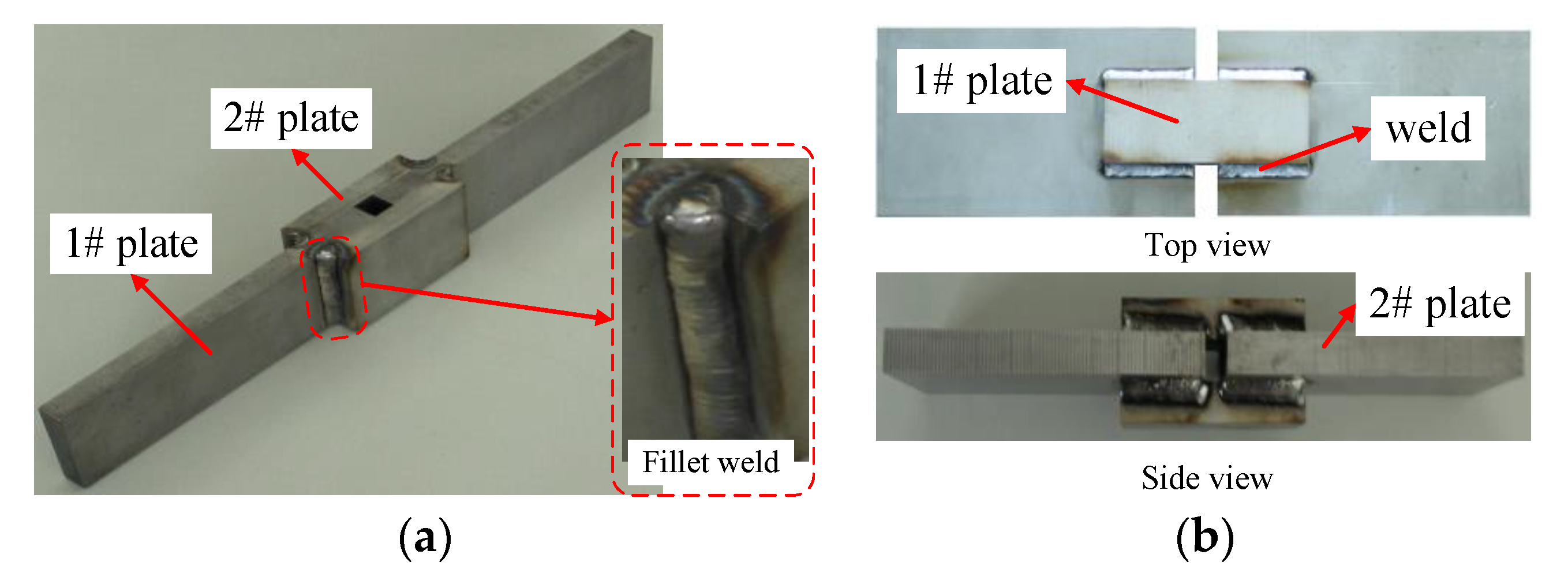
According to the AWS (American Welding Society) 2007 (Standard Methods for Mechanical Testing of Welds) [18], load-carrying capacities of welded joints are tested by standard transverse and longitudinal welded specimens. Figure 1 shows the AWS standard test specimens. The transverse welded specimens are composed of four plates with a thickness of 10 mm. The size of 1# plate is 145 mm × 50 mm, while 2# plate is 60 mm × 50 mm. Four plates are connected by four fillet welds. Arc welding is adopted and the length and height of the fillet weld leg are designed to be 3 mm. The longitudinal welded specimen is similar to the transverse welded specimen. The only difference is the size of plates. The sizes of 1# and 2# plates of the longitudinal welded specimen are 145 mm × 70 mm and 90 mm × 30 mm, respectively.
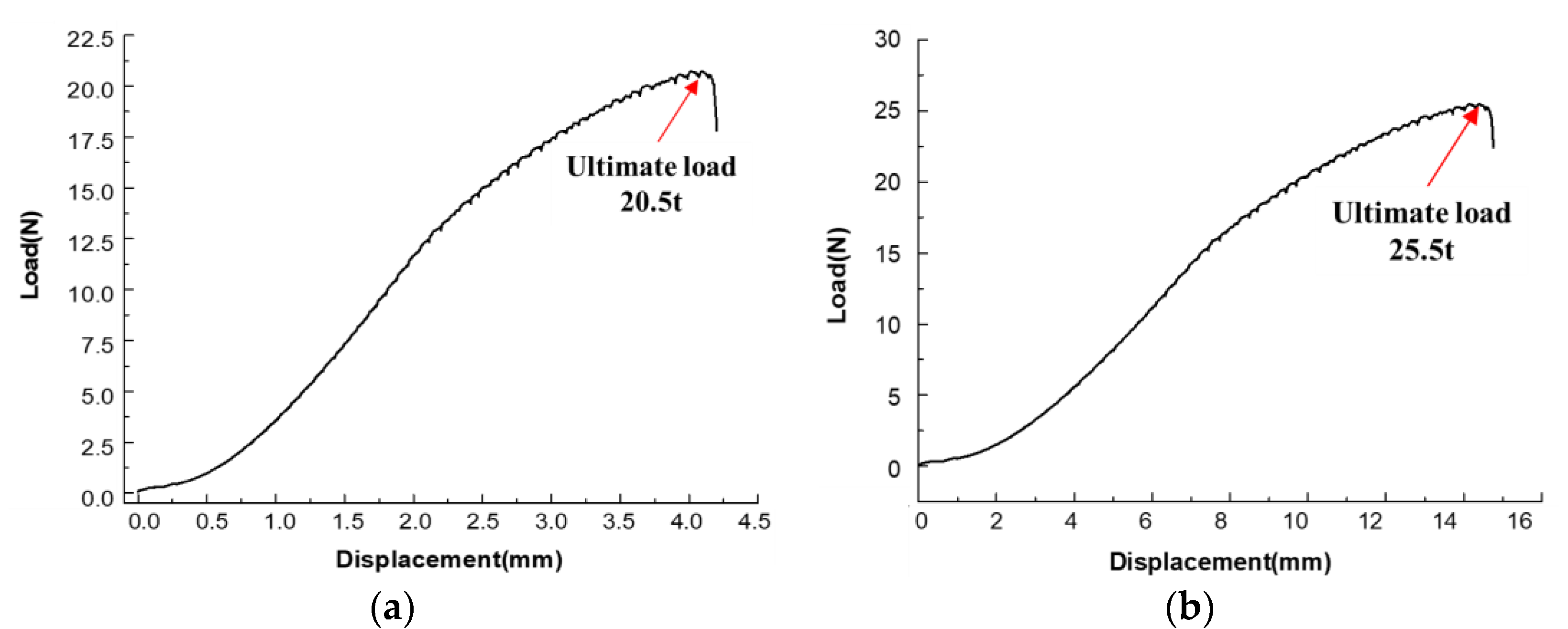
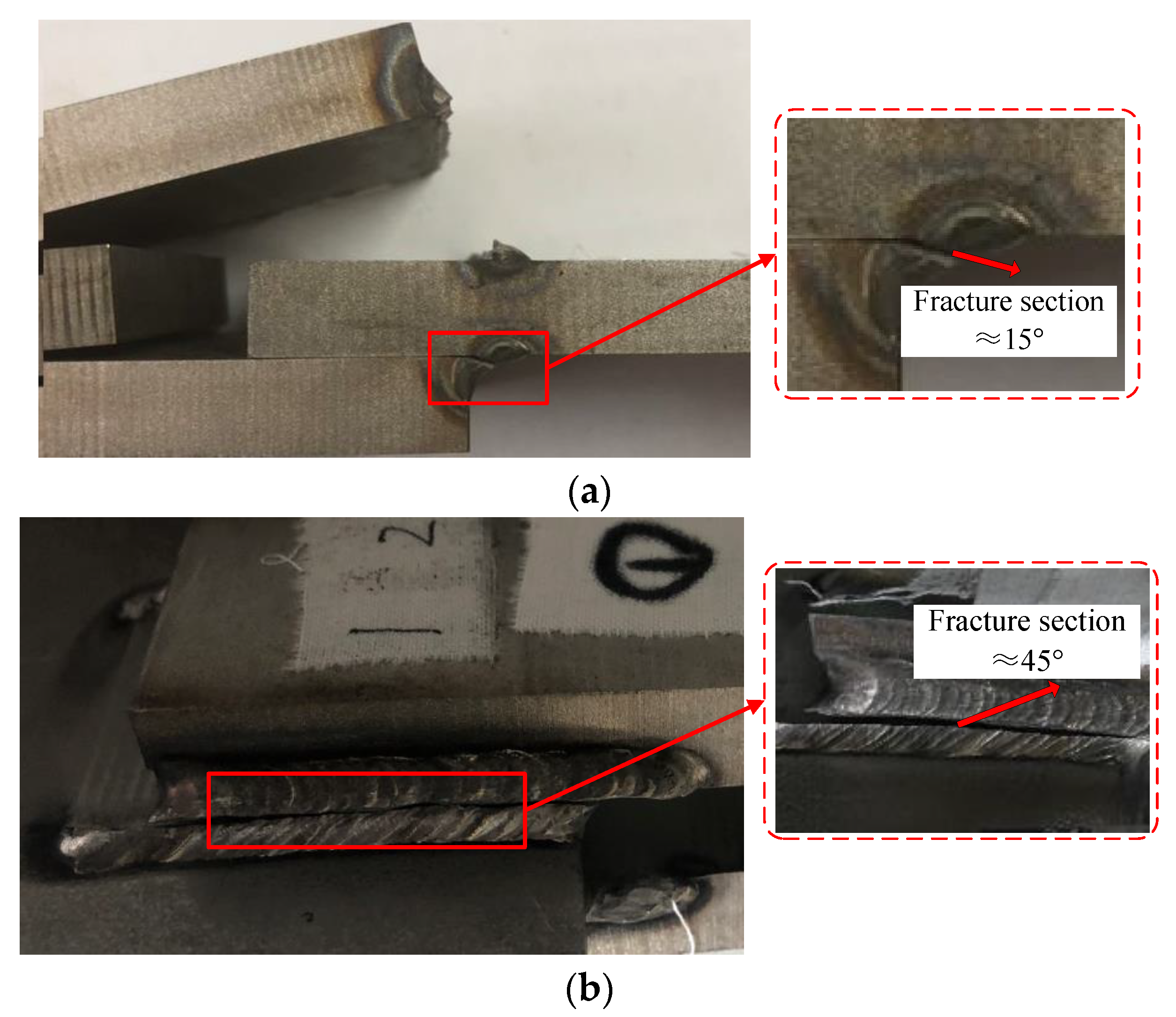
Firstly, the load-carrying capacities of these two types of welded joints were tested. During the loading test, one end of the specimen is clamped and the other end is subjected to a tensile load. The displacement control method was adopted and its rate was controlled at 0.5 mm/min. Figure 2 shows the tensile load-displacement curves of the specimens. The nonlinearity in the initial stage is mainly caused by the gradual clamping process between the clamp and the specimen. Both transverse and longitudinal welded specimens fractured shortly after the plastic yield, indicating that the elongation of the weld metal is relatively low. The load-carrying capacities of transverse and longitudinal welded specimens are 20.5 t and 25.5 t, respectively. Figure 3 shows the failure fractures of the welded joints. Among them, Figure 3a shows the fracture cross-section angle of the medium transverse welded specimen with the plate surface of approximately 15°; Figure 3b shows the fracture cross-section angle of the medium longitudinal welded specimen with the plate surface of approximately 45°.
3. Analysis of Structural Stress
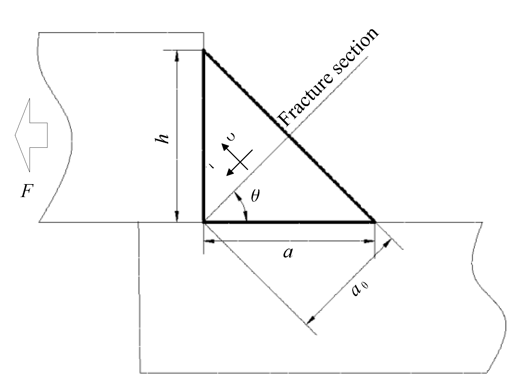
Figure 4 shows the stress status of the fillet weld. The length and height of the fillet weld leg are and , respectively. The weld fracture occurs at the section angle under the effect of load . AWS 2007 gives a calculation formula for fillet weld shear stress as shown in Equation (1):
where, is the length of the weld throat in the fracture section, and is the length of the weld.
In practical engineering applications, the geometry of fillet welds can be complex, therefore, it is impossible to specify the load and throat length of the fillet weld directly. At the same time, an obvious stress concentration was noted in the local area. Due to the sensitivity of element shape and type in the conventional finite element method (FEM), the results cannot be directly applied to the evaluation of the stress state of fillet welds.
The structural stress method is a fatigue life prediction method proposed by Dong [7,8,9], aiming at the particularity of the fatigue problem in welded structures. The typical feature of this method is that it is insensitive to the element type, shape and size of the mesh. The stress along the weld throat is divided into structural stress balanced with external force and self-balanced notch stress. Structural stress can be expressed as Equation (2).
where is the structural stress of every node, denotes the nodal force, is the nodal moment, refers to the equivalent matrix of element length and describes the thickness of the plate. The relationship between line force and nodal force can be expressed as Equation (3), while the relationship between the line moment and nodal moment can be expressed as Equation (4), similarly.
Then, the membrane stress and bending stress uniformly distributed along the weld throat can be obtained by following Equations (5) and (6), respectively.
So, the structural stress of the selected weld throat section can be expressed as Equation (7).
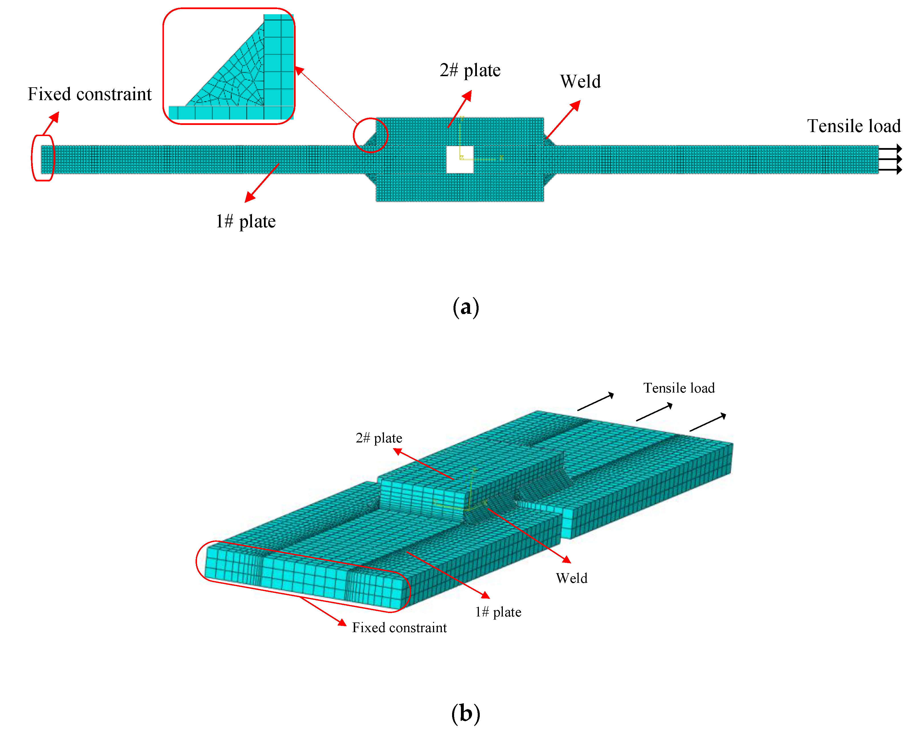
To explain the analysis of structural stress, an FE model was developed in a commercial FEM software ABAQUS. Figure 5 shows the FE models of the transverse and longitudinal welded specimens, respectively. The transverse and longitudinal weld sample models are meshed in Hyper mesh. Plane strain elements were employed in the transverse welded specimen, while the hexahedral element was adopted in the longitudinal welded specimen. The contact interaction was defined between the four plates, and all of the plates were tied to the weld. The structural stress method is based on the nodal force, which is not affected by the material properties. Therefore, the material property of the weld was set to be the same as that of the plates. The length and height of weld legs were obtained based on actual measured results. One end of the model was restrained by fixed constraint, and the other one was subjected to tensile load. Based on the test results, the tensile loads were set as 20.5 t and 25.5 t for transverse and longitudinal welded structures, respectively.
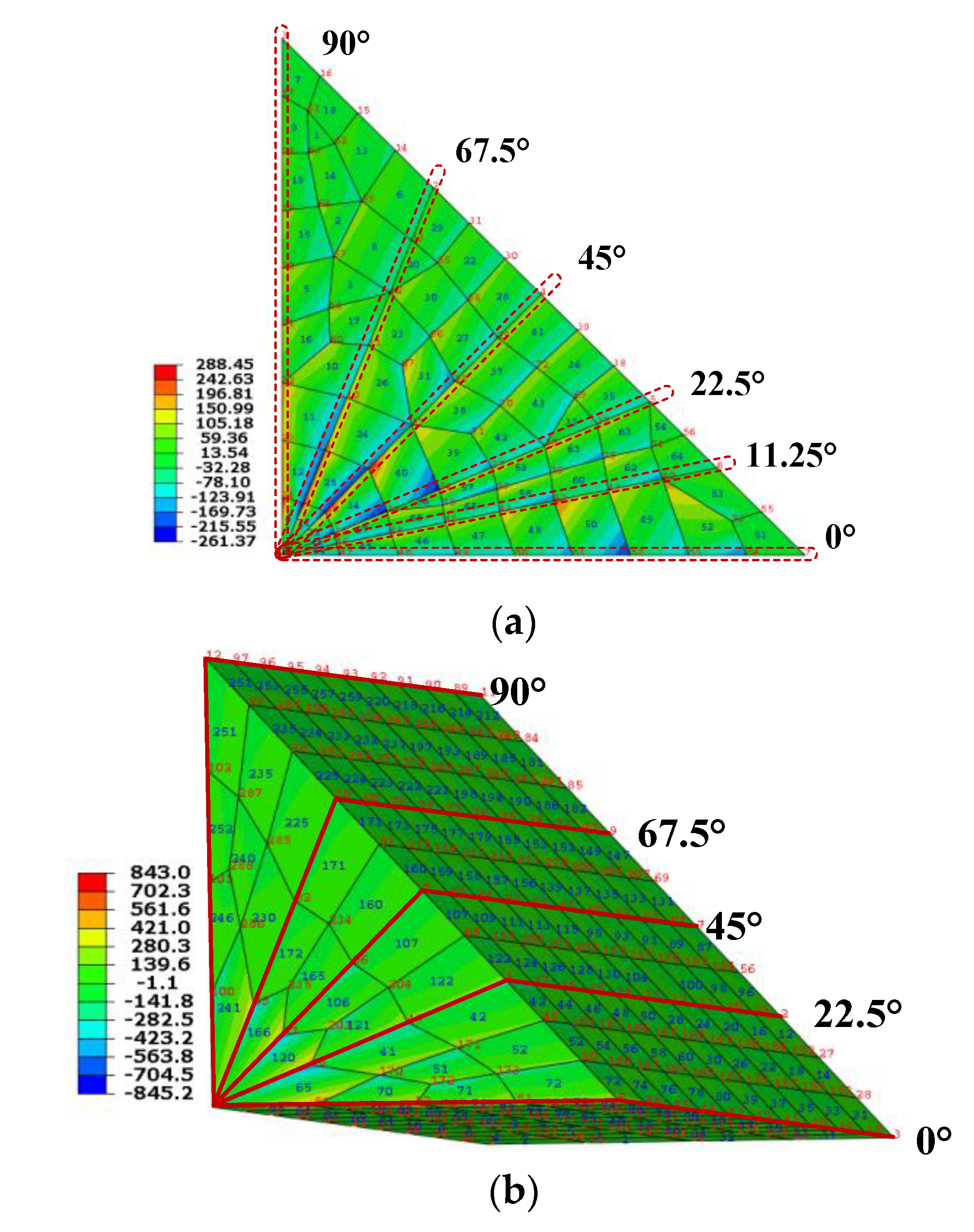
Figure 6 depicted the nodal force of different sections under the tensile load. The normal and shear nodal force of different sections were extracted, respectively, and the normal and shear components of structural stress can be calculated based on Equations (2)–(7). Thus, we can accurately obtain the stress status of the weld based on the structural stress method. It should be noted that the analysis results are independent of the mesh quality and weld material properties.
4. Weld-Failure Stress
There are three typical methods of defining the effective stress as shown in Equations (8)–(10) for the analysis of static strength, which have also been mentioned in reference [16]. Among them, Equation (8) is based on the assumption that when the vector sum of the normal and shear traction components reaches its limit value, static failure will occur along the cutting plane, while Equation (9) is based on the assumption that when the Von Mises stress of the traction stress component reaches its limit value, failure will occur. Equation (9) simply points out that failure will occur when the average shear stress on the cutting plane reaches its limit state.
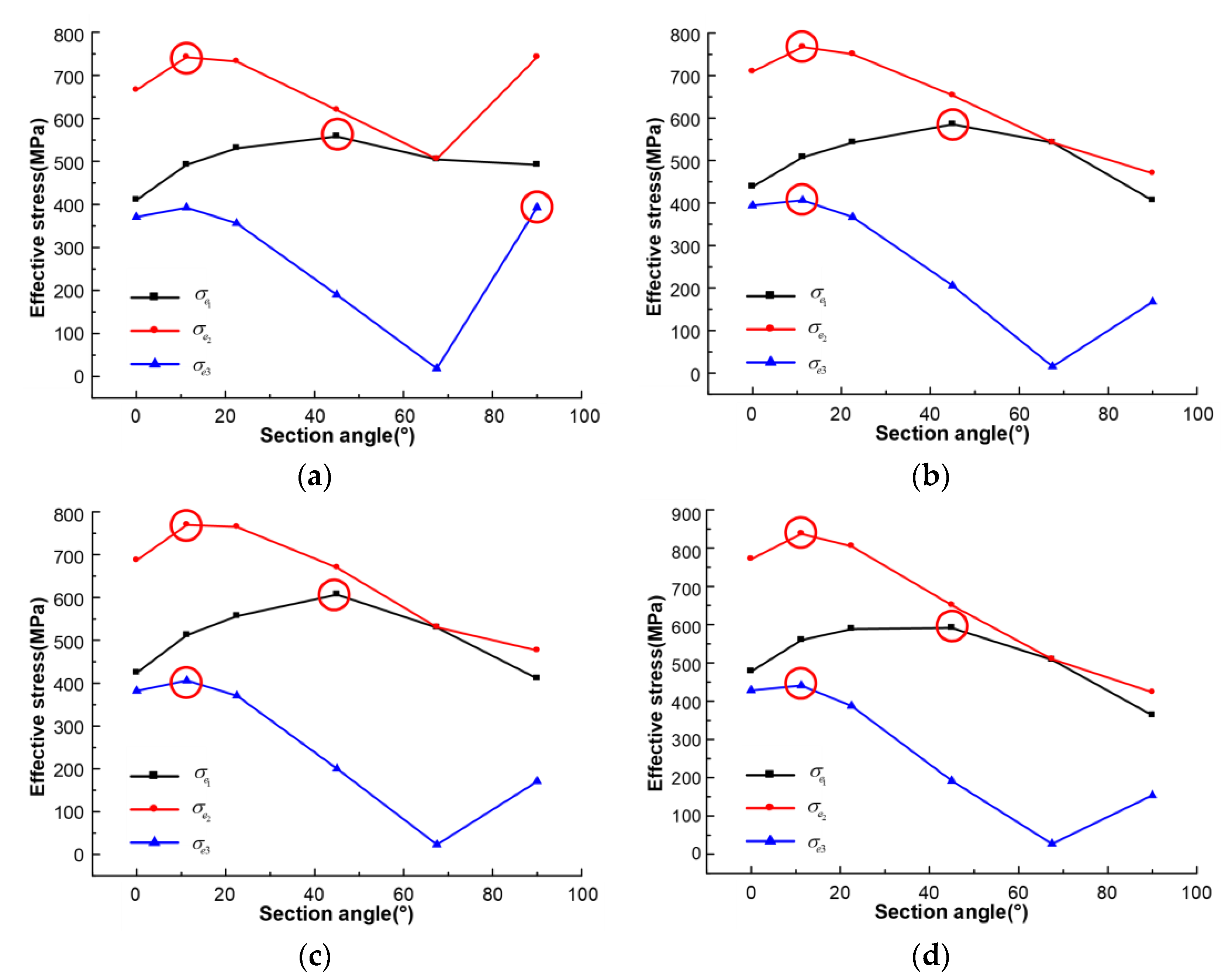
For the transverse fillet weld, the normal and shear stress of different weld sections can be obtained according to the nodal force in Figure 6a. Because the loads applied in the FE model are fracture loads obtained by tests, these stress components directly reflect the ultimate bearing capacity of the welded structure. According to Equations (8)–(10), the characterizations of three typical effective stresses on different weld sections can be obtained as shown in Figure 7, where the red circle represents the maximum value of effective stress in different weld sections. Two important conclusions can be drawn from Figure 7. (1) For the same weld, the section angles of maximum stress in three different effective stress methods are different, and (2) the section angle of the maximum stress obtained by the effective stress method is consistent in each weld.
The section of maximum effective stress is the fracture section of the weld, while the corresponding effective stress is the failure stress of the weld. We define it as the weld-failure stress in this study. The effective stress method can accurately describe the fracture section of the weld and is consistent in different welds. Therefore, a preliminary conclusion can be drawn that the effective stress definition method can be used to evaluate the load-carrying capacity of welds accurately. The effective stress of 2# weld is the largest, while 2# and 4# welds are fractured in the test. Therefore, we take the effective stress of 2# weld as the weld-failure stress, which is 837.8 MPa.
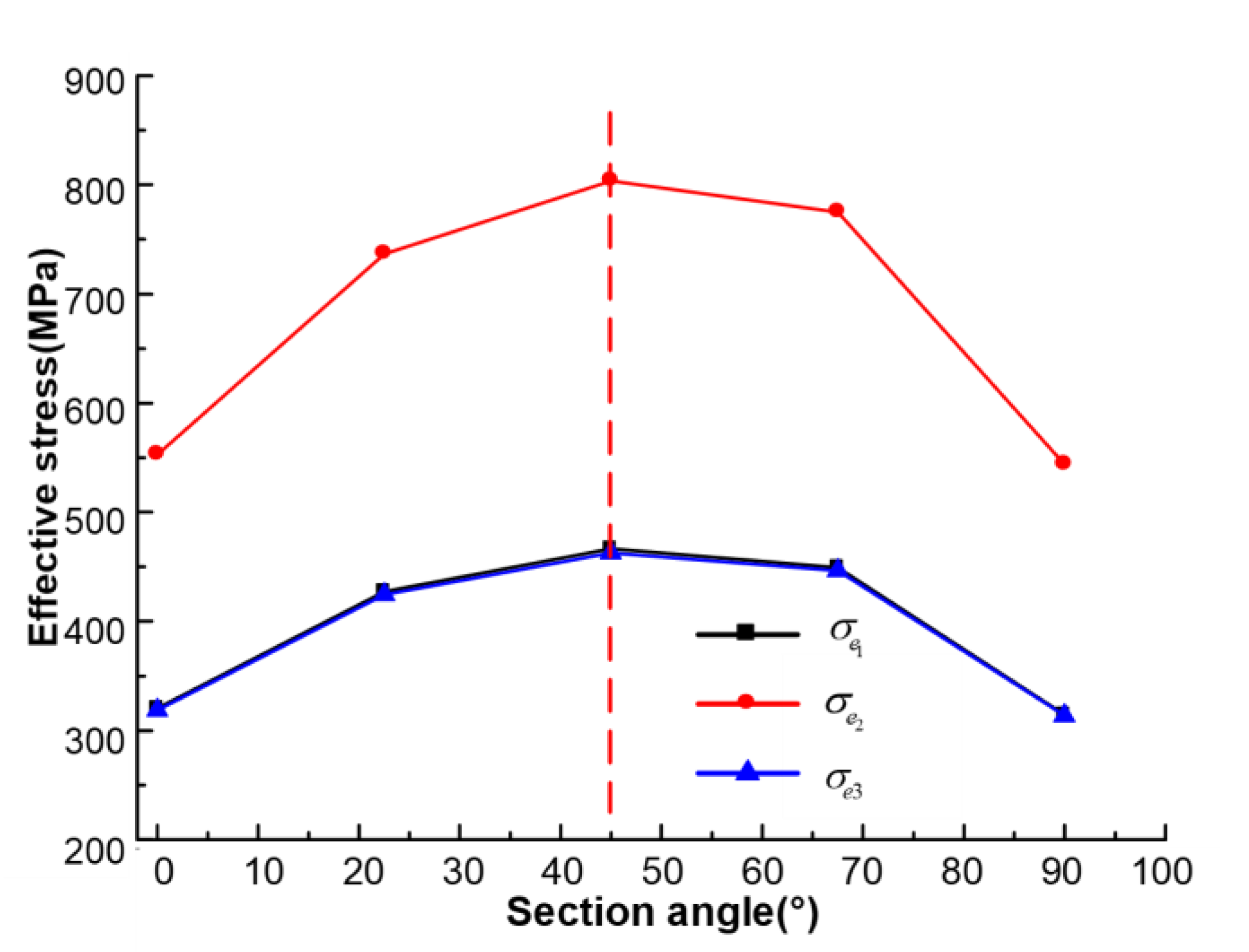
Three typical effective stress methods were also used to analyze the stress status of longitudinal fillet weld. Eight fillet welds show the same characteristics in different sections. Figure 8 shows the effective stress of different sections of a selected weld. It can be seen that the section angle of maximum effective stress is 45° in the three typical methods. In order to maintain consistency with the evaluation method of transverse welded specimens, the effective stress definition method was also selected to evaluate the load-carrying capacity of the longitudinal fillet weld. The weld-failure stress obtained through the longitudinal fillet weld is 803.5 MPa. The relative error of weld-failure stress obtained by two kinds of fillet welds is 4%, which also includes the deviation of material properties caused by the welding process.
5. Engineering Application in a Rocket Engine Frame
5.1. Rocket Engine Frame
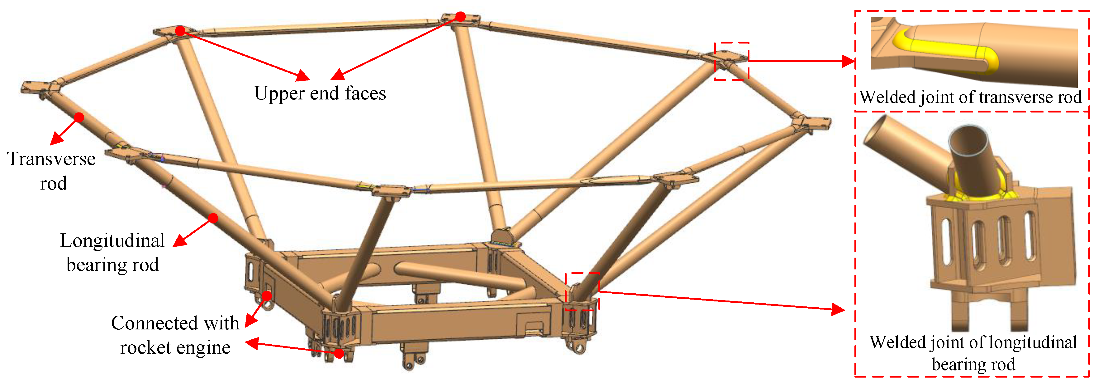
The rocket engine frame is designed with a truss structure of thin-walled pipes. Figure 9 shows the frame structure and local welded joints. The upper end face of the frame is connected with the rocket cabin by eight connecting end faces. Those connecting end faces are joined by eight transverse rods, so as to reduce the radial deformation of the upper connecting end face. The lower end face is connected to four rocket engines and their hydraulic servos. The upper and lower end faces are connected with eight longitudinal bearing rods, through which the thrust of engines is transferred to the cabin of the rocket.
There are two types of welded joints: transverse and longitudinal welded joints. The welded joint of the transverse rod is a typical U-shaped lap fillet weld, while that of the longitudinal bearing rod is a pipe-plate fillet weld. The transverse rod mainly bears the tensile load which restrains the radial deformation of the end face, and the longitudinal rod is mainly subjected to the compression load in the thrust transfer.
The diameters of transverse and longitudinal rods are both 60 mm, and the thickness is 2.5 mm. Arc welding is adopted and the electrode is E5015 with a diameter of 2.5 mm. The welding current is 40–50 A, and the welding speed is 120–130 mm/min [19]. The material of the structures is 30CrMnSiA steel and H18CrMoA was adopted as the welding wire. Before welding, heat treatment should be carried out to strengthen the frame, and abrasive blasting should be performed to clean the oil and oxide layer, to prevent pores, slag inclusion, cracks and other defects. The material of the frame is a kind of medium carbon, quenched and tempered structural steel with a poor weldability. Therefore, the bearing capacity of these two types of fillet welds should be paid attention to.
5.2. Typical Welded Specimens Test
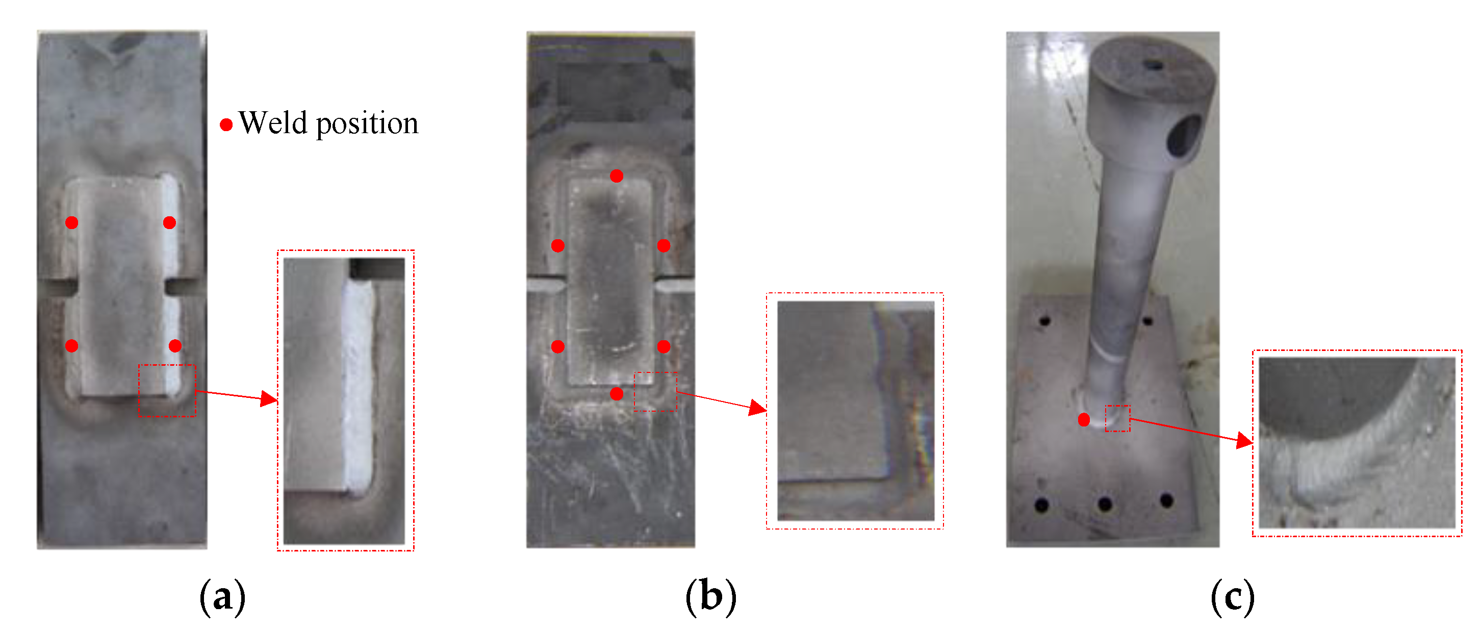
To obtain the weld-failure stress of the frame, three typical types of welded specimens as shown in Figure 10 were tested, which are standard shear specimens according to AWS 2007, U-shaped fillet welded specimens for the welded joints of transverse rods and pipe-plate fillet welded specimens for the welded joints of longitudinal bearing rods. The material and welding processing parameters of the specimens were consistent with those of the frame. Six specimens of each type were processed.
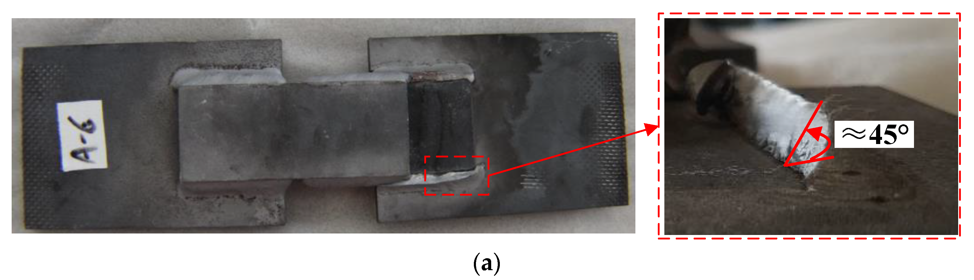
Tensile tests were carried out for three types of welded specimens. The results are shown in Figure 11. The failure fracture of the standard shear specimen occurs at an angle of approximately 45° to the plate, which is in good agreement with the results obtained in Part 2. The fracture section angle is the same in the six standard shear specimens, while the ultimate load-carrying capacities are in the range of 54 t to 57 t. For the U-shaped fillet welded specimen, the fracture section is approximately 45° at the longitudinal fillet weld and 22.5° at the transverse fillet weld. They are also the same as those of the single longitudinal and transverse fillet welds. The ultimate load-carrying capacities of six U-shaped fillet welded specimens are in the range of 92 t to 94 t. In the pipe-plate fillet welded specimen, shear fracture occurs at 1/3 of the weld while the rest occurs at the weld toe. From the fracture section, it is found that the fracture occurs at the weld first, and then leads to the tear of the weld toe. The ultimate load-carrying capacities of six pipe-plate fillet welded specimens are in the range of 47 t to 49 t.
5.3. Analysis of Weld-Failure Stress
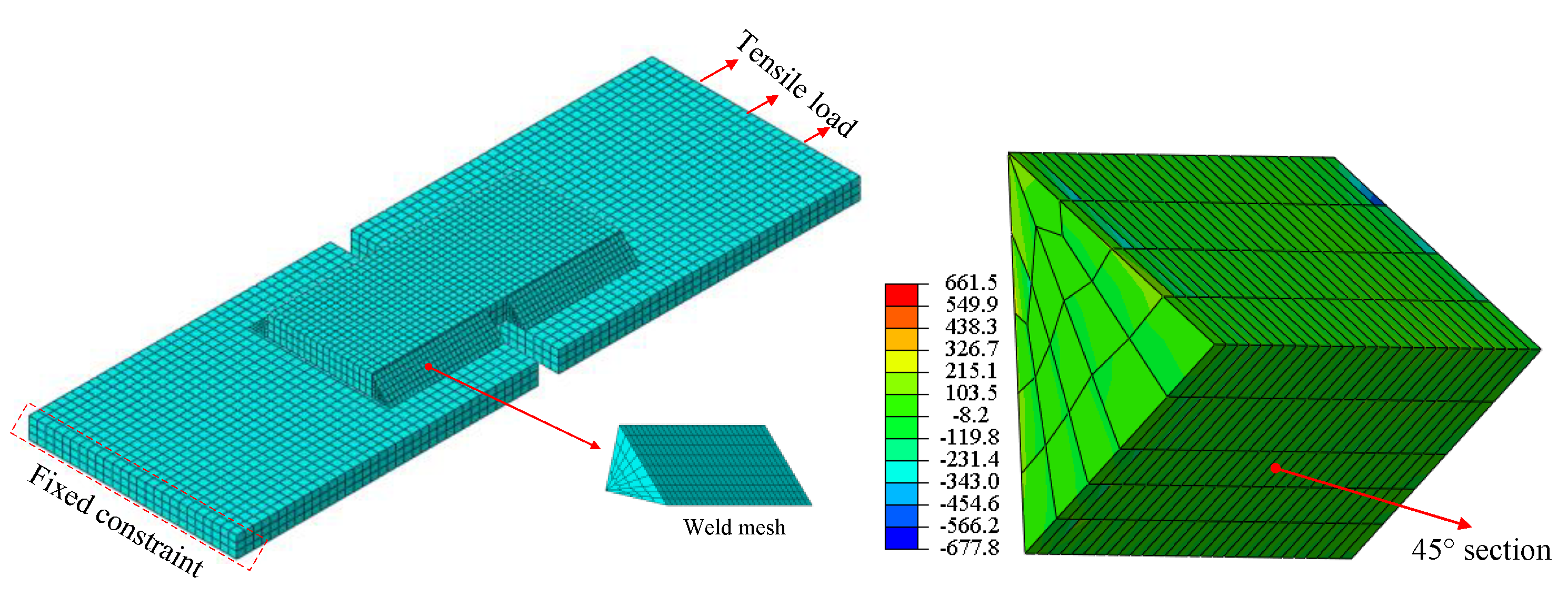
The standard shear sample mesh model is drawn in Hyper mesh software and imported into ABAQUS software for numerical analysis. The FE model and nodal force distribution of the standard shear specimen are shown in Figure 12. The modelling method was consistent with what we mentioned above, and the tensile load is set as 55.8 t, which is the average load of test results. According to the results in Figure 11a, the weld-failure stress was obtained based on the nodal force of the 45° section, i.e., 605 MPa.
The same analysis method was carried out on the U-shaped fillet welded specimen by drawing the mesh model of the U-shaped fillet welding specimen in Hyper mesh software, and importing it into ABAQUS software for numerical analysis. Its FE model and nodal force distribution are shown in Figure 13. The tensile load is set as the average value of the test results. The results of the 45° section of the longitudinal weld and 22.5° section of the transverse weld were extracted, respectively. The weld-failure stress, 623 MPa, is analyzed considering the results of these welds.
The FE model of the pipe-plate fillet-welded specimen is shown in Figure 14. According to the symmetry of the specimen, an axisymmetric model was adopted and its parameters were determined according to the actual measurement. The tensile load was set as 48 t, which is also the average value of the test results. Weld effective stress of five sections at different angles of 0°, 22.5°, 45°, 67.5° and 90° were analyzed. The maximum effective stress occurs at the section of 22.5°, which is the same as the test result in Figure 11c. That is the weld-failure stress, i.e., 620.7 MPa.
To compare and illustrate the effectiveness of the weld-failure stress in this work, three other classical strength theories were adopted and compared as well. They are the maximum tensile stress theory, the maximum principal shear stress theory and the Von-Mises theory. The results of different theories are shown in Figure 15. It is observed that the weld-failure stress obtained by the proposed method has the least deviation—18 MPa. The analysis method proposed in this paper has stable analysis results in three different types of welded specimens. The deviations of the other three classic strength theories are all relatively large. It is 195 MPa in the maximum tensile stress theory, 339 MPa in the maximum principal shear stress theory and 329 MPa in the Von-Mises theory.
Thus, the weld-failure stress of the rocket engine frame can be obtained, which is in the range of 605 MPa to 623 MPa. We conservatively take the value of 605 MPa for the load-carrying capacity evaluation of the rocket engine frame.
5.4. Load-Carrying Capacity Evaluation
The FE model of the rocket engine frame was established as shown in Figure 16. The upper end face of the frame was connected to the rocket cabin. The fixed constraint was set to the upper end face of the rocket cabin. The thrust of the rocket was loaded at the lower end face of the frame. A shell element was adopted in the rocket cabin, while solid element was chosen for the frame. The weld, which is the main concern of this work, was simulated with actual geometrical parameters and discretized with solid elements.
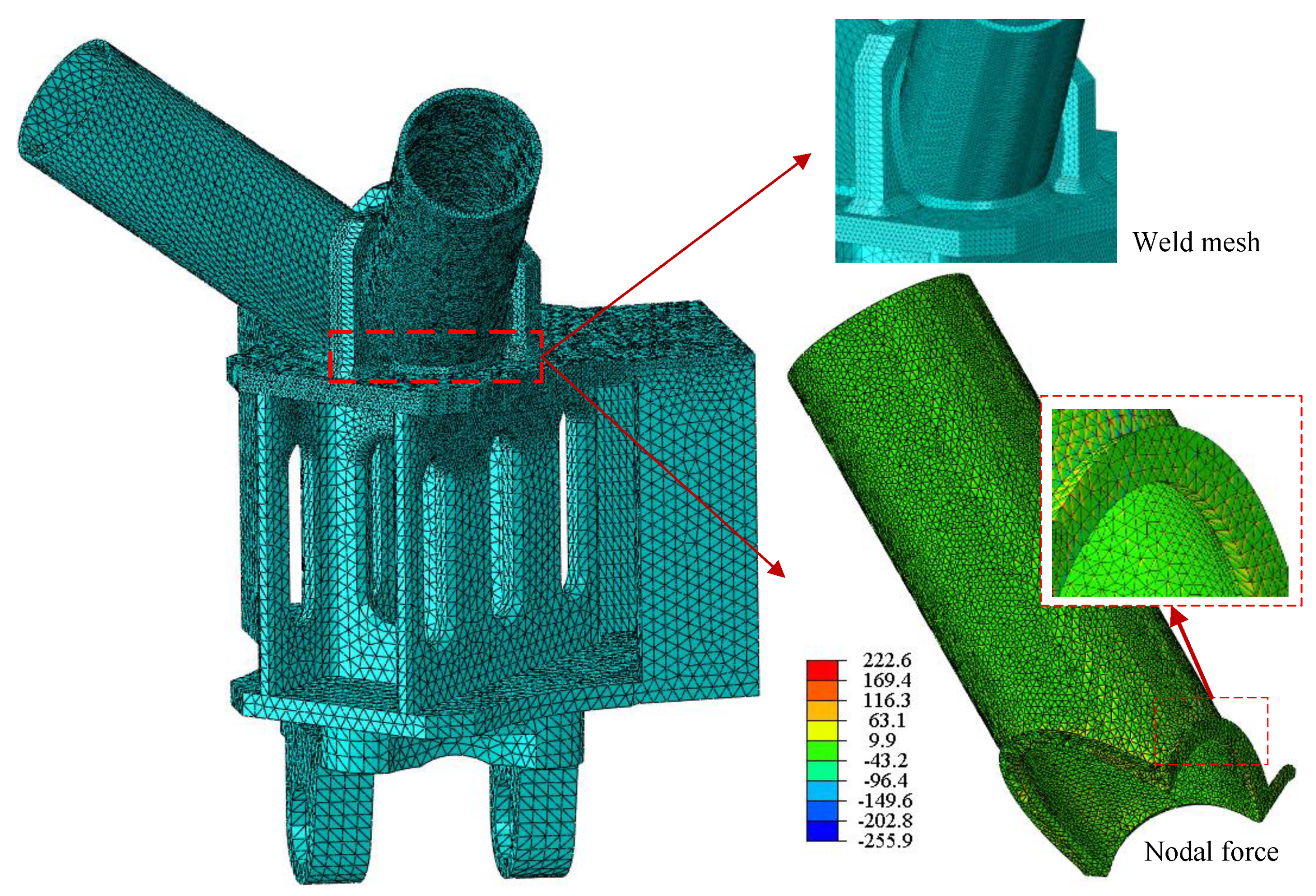
In this work, we focus on the welded joints of transverse rod and longitudinal bearing rods shown in Figure 9. Their local mesh and nodal force distributions are shown in Figure 17 and Figure 18, respectively. In the tests of typical welded specimens, the failure position located at the welded area, and no buckling phenomenon was observed, thus we only focused on the failure of the weld toe in the numerical study. According to the test results, the structural stress of the 45° section for the transverse weld and the 22.5° section for the longitudinal weld were analyzed. Their effective stress is 70.2 MPa and 45.3 MPa, respectively. The weld-failure stress is 605 MPa. Hence, the safety factors of transverse rod and longitudinal bearing rod welded joints are 8.6 and 13.4, respectively.
6. Conclusions
In this paper, a load-carrying capacity evaluation method of welded joints based on the Structural Stress Method was proposed, while a definition of weld-failure stress was given. Then, the effectiveness of the evaluation method was verified by test results. The following conclusions can be drawn:
(1) Both the ultimate load-carrying capacity and the fracture section angle can be precisely obtained by the evaluation method, which has been validated by tests.
(2) The load-carrying capacities of three types of welded structures, standard shear specimen, U-shaped fillet welded specimen and pipe-plate fillet welded specimen, were tested and analyzed for the welded joints of a rocket engine frame. The welded failure stress of frame welded joints was obtained and verified through comparisons with the other three typical strength theories.
(3) The load-carrying capacity of the welded joints of the rocket engine frame was effectively evaluated through the finite element model including the overall structure and local weld details. The safety factors of transverse rod and longitudinal bearing rod welded joints are 8.6 and 13.4, respectively.
Author Contributions
Conceptualization, Y.G.; methodology, S.H.; software, Y.G.; validation, P.W. and P.Z.; formal analysis, Y.G.; investigation, P.W.; resources, S.H.; data curation, Y.G.; writing—original draft preparation, Y.G.; writing—review and editing, P.W.; visualization, P.Z.; supervision, S.H.; project administration, S.H.; funding acquisition, S.H. All authors have read and agreed to the published version of the manuscript.
Funding
This research was funded by the National Natural Science Foundation of China, grant number No. 52005385.
Institutional Review Board Statement
Not applicable.
Informed Consent Statement
Not applicable.
Data Availability Statement
The data is reflected in the paper as required.
Conflicts of Interest
The authors declare no conflict of interest.
References
- Huo, S.; Yuan, J.; Xu, X.; Yang, S. A rapid optimization design method for frame structure of double thrust chambers. J. Rocket Propuls. 2015, 41, 55–60. [Google Scholar]
- Bertini, L.; Cera, A.; Frendo, F. Experimental investigation of the fatigue resistance of pipe-to-plate welded connections under bending torsion and mixed mode loading. Int. J. Fatigue 2014, 68, 178–185. [Google Scholar] [CrossRef]
- Pyttel, B.; Grawenhof, P.; Berger, C. Application of different concepts for fatigue design of welded joints in rotating components in mechanical engineering. Int. J. Fatigue 2012, 34, 35–46. [Google Scholar] [CrossRef]
- Hobbacher, A.F. Recommendations for Fatigue Design of Welded Joints and Compinents; IIW Document IIW-1823-07; International Institute of Welding: Swiss, Switzerland, 2008. [Google Scholar]
- Hobbacher, A.F.; Hobbacher, A.F. Recommendations for Fatigue Design of Welded Joints and Components; Springer International Publishing: Cham, Switzerland, 2016. [Google Scholar]
- Poutiainen, I.; Tanskanen, P.; Marquis, G. Finite element approach for structural hot spot stress determination-a comparison of procedures. Int. J. Fatigue 2004, 26, 1147–1157. [Google Scholar] [CrossRef]
- Dong, P.S. A Robust Structural Stress Procedure for Characterizing Fatigue Behavior of Welded Joints; SAE Technical Paper No. 2001-01-0086; Center for Welded Structures Research, Battelle: Columbus, OH, USA, 2001. [Google Scholar]
- Dong, P.S. A structural stress definition and numerical implementation for fatigue analysis of welded joints. Int. J. Fatigue 2001, 23, 865–876. [Google Scholar] [CrossRef]
- Dong, P.S.; Hong, J.K. CAE Weld Durability Prediction: A Robust Single Damage Parameter Approach; SAE Technical Paper No. 2002-01-0151; Center for Welded Structures Research, Battelle: Columbus, OH, USA, 2002. [Google Scholar]
- Milivoje, J.; Ivica, Č.; Aleksandar, S.; Zijah, B.; Simon, S.; Predrag, Ž. Analysis of SA 387 Gr. 91 welded joints crack resistance under static and impact load. Procedia Struct. Integr. 2021, 31, 38–44. [Google Scholar]
- Ameri, A.A.H.; Davison, J.B.; Susmel, L. On the use of linear-elastic local stresses to design load-carrying fillet-welded steel joints against static loading. Eng. Fract. Mech. 2015, 136, 38–57. [Google Scholar] [CrossRef]
- Yang, L.; Cui, Y.; Wei, X.; Li, M.; Zhang, Y. Strength of duplex stainless steel fillet welded connections. J. Constr. Steel Res. 2019, 152, 246–260. [Google Scholar] [CrossRef]
- Ahola, A.; Bjork, T.; Barsoum, Z. Fatigue strength capacity of load-carrying fillet welds on ultra-high-strength steel plates subjected to out-of-plane bending. Eng. Struct. 2019, 196, 109282. [Google Scholar] [CrossRef]
- Takeshi, H.; Kazuo, T.; Suguru, K.; Masaru, S. Correction: Effect of static load during HFMI treatment on fatigue strength and residual stress field of longitudinal atachment welded joints. Weld. World 2022, 66, 845. [Google Scholar]
- Varbai, B.; Sommer, C.; Szabo, M.; Toth, T.; Majlinger, K. Shear tension strength of resistant spot welded ultra high strength steels. Thin-Walled Structres 2019, 142, 64–73. [Google Scholar] [CrossRef]
- Nie, C.; Dong, P. A traction stress based shear strength definition for fillet welds. J. Strain Anal. 2012, 47, 562–575. [Google Scholar] [CrossRef]
- Lu, H.; Dong, P.; Boppudi, S. Strength analysis of fillet welds under longitudinal and transverse shear conditions. Mar. Struct. 2015, 43, 87–106. [Google Scholar] [CrossRef]
- AWS B4.0; Standard Methods for Mechanical Testing of Welds. American Welding Society, Inc: Miami, FL, USA, 2007.
- Liang, Y.L.; Yang, W.H. Research on welding process of small diameter thin wall bar system truss. Hot Work. Technol. 2017, 46, 190–193. [Google Scholar]
Figure 1.
AWS standard test specimens: (a) transverse welded specimen; (b) longitudinal welded specimen. (1# and 2# indicate the plate sequence number).
Figure 1.
AWS standard test specimens: (a) transverse welded specimen; (b) longitudinal welded specimen. (1# and 2# indicate the plate sequence number).

Figure 2.
Tensile load-displacement curves of the specimens: (a) transverse welded specimen; (b) longitudinal welded specimen.
Figure 2.
Tensile load-displacement curves of the specimens: (a) transverse welded specimen; (b) longitudinal welded specimen.

Figure 3.
Failure fractures of the welded joints: (a) transverse welded specimen; (b) longitudinal welded specimen.
Figure 3.
Failure fractures of the welded joints: (a) transverse welded specimen; (b) longitudinal welded specimen.

Figure 4.
Stress status of fillet weld.

Figure 5.
FEM of welded structures: (a) transverse welded specimen; (b) longitudinal welded specimen. (1# and 2# indicate the plate sequence number).
Figure 5.
FEM of welded structures: (a) transverse welded specimen; (b) longitudinal welded specimen. (1# and 2# indicate the plate sequence number).

Figure 6.
Nodal force of different sections: (a) transverse welded specimen; (b) longitudinal welded specimen.
Figure 6.
Nodal force of different sections: (a) transverse welded specimen; (b) longitudinal welded specimen.

Figure 7.
Typical effective stress of different weld sections in transverse fillet weld: (a) 1# weld; (b) 2# weld; (c) 3# weld; (d) 4# weld. (The red circle indicates the highest stress level of the curve).
Figure 7.
Typical effective stress of different weld sections in transverse fillet weld: (a) 1# weld; (b) 2# weld; (c) 3# weld; (d) 4# weld. (The red circle indicates the highest stress level of the curve).

Figure 8.
Effective stress of different weld section angles in the longitudinal fillet weld.

Figure 9.
The frame structure and local welded joints.

Figure 10.
Typical welded specimens of the frame: (a) standard shear; (b) U-shaped fillet welded; (c) pipe-plate fillet welded.
Figure 10.
Typical welded specimens of the frame: (a) standard shear; (b) U-shaped fillet welded; (c) pipe-plate fillet welded.

Figure 11.
Failure fractures of the welded specimens: (a) standard shear specimen; (b) U-shaped fillet welded specimen; (c) pipe-plate fillet welded specimen.
Figure 11.
Failure fractures of the welded specimens: (a) standard shear specimen; (b) U-shaped fillet welded specimen; (c) pipe-plate fillet welded specimen.


Figure 12.
FEM and nodal force distribution of the standard shear specimen.

Figure 13.
FEM and nodal force distribution of the U−shaped fillet welded specimen.

Figure 14.
FEM and nodal force distribution of the tube-plane fillet welded specimen.

Figure 15.
The results of different strength theories.

Figure 16.
FEM of the rocket engine frame.

Figure 17.
FEM and nodal force of the transverse rod welded joint.

Figure 18.
FEM and nodal force of the longitudinal bearing rod welded joint.

Disclaimer/Publisher’s Note: The statements, opinions and data contained in all publications are solely those of the individual author(s) and contributor(s) and not of MDPI and/or the editor(s). MDPI and/or the editor(s) disclaim responsibility for any injury to people or property resulting from any ideas, methods, instructions or products referred to in the content. |
© 2023 by the authors. Licensee MDPI, Basel, Switzerland. This article is an open access article distributed under the terms and conditions of the Creative Commons Attribution (CC BY) license (https://creativecommons.org/licenses/by/4.0/).
Share and Cite
MDPI and ACS Style
Gao, Y.; Huo, S.; Wang, P.; Zhang, P. A Load-Carrying Capacity Evaluation Method for the Welded Joints of Rocket Engine Frame. Aerospace 2023, 10, 324. https://doi.org/10.3390/aerospace10040324
AMA Style
Gao Y, Huo S, Wang P, Zhang P. A Load-Carrying Capacity Evaluation Method for the Welded Joints of Rocket Engine Frame. Aerospace. 2023; 10(4):324. https://doi.org/10.3390/aerospace10040324
Chicago/Turabian StyleGao, Yushan, Shihui Huo, Peiyan Wang, and Ping Zhang. 2023. "A Load-Carrying Capacity Evaluation Method for the Welded Joints of Rocket Engine Frame" Aerospace 10, no. 4: 324. https://doi.org/10.3390/aerospace10040324
Note that from the first issue of 2016, this journal uses article numbers instead of page numbers. See further details here.