
Design and Evaluation on Onboard Antenna Pointing Control System for a Wireless Relay System Using Fixed-Wing UAV
Abstract
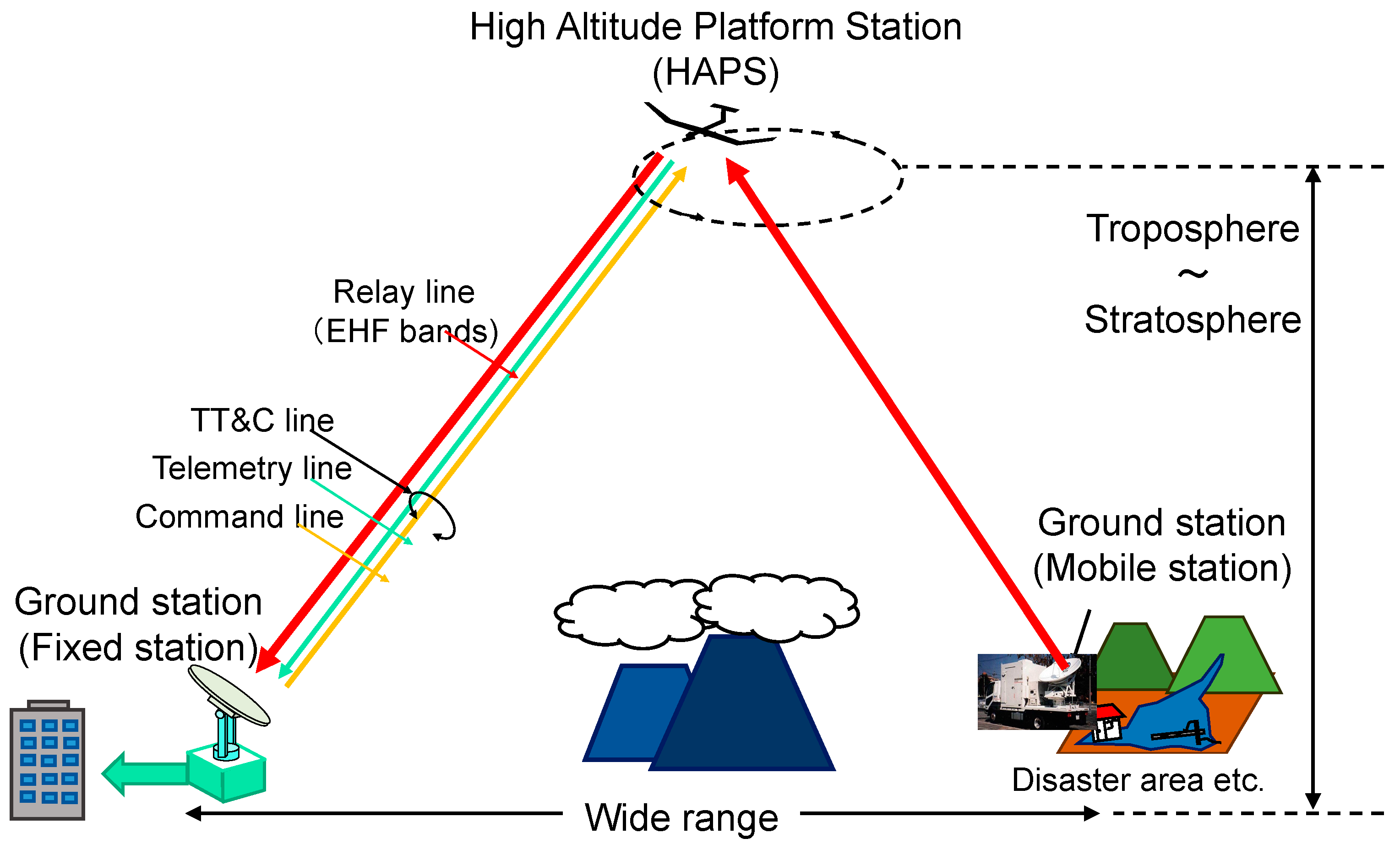
:1. Introduction
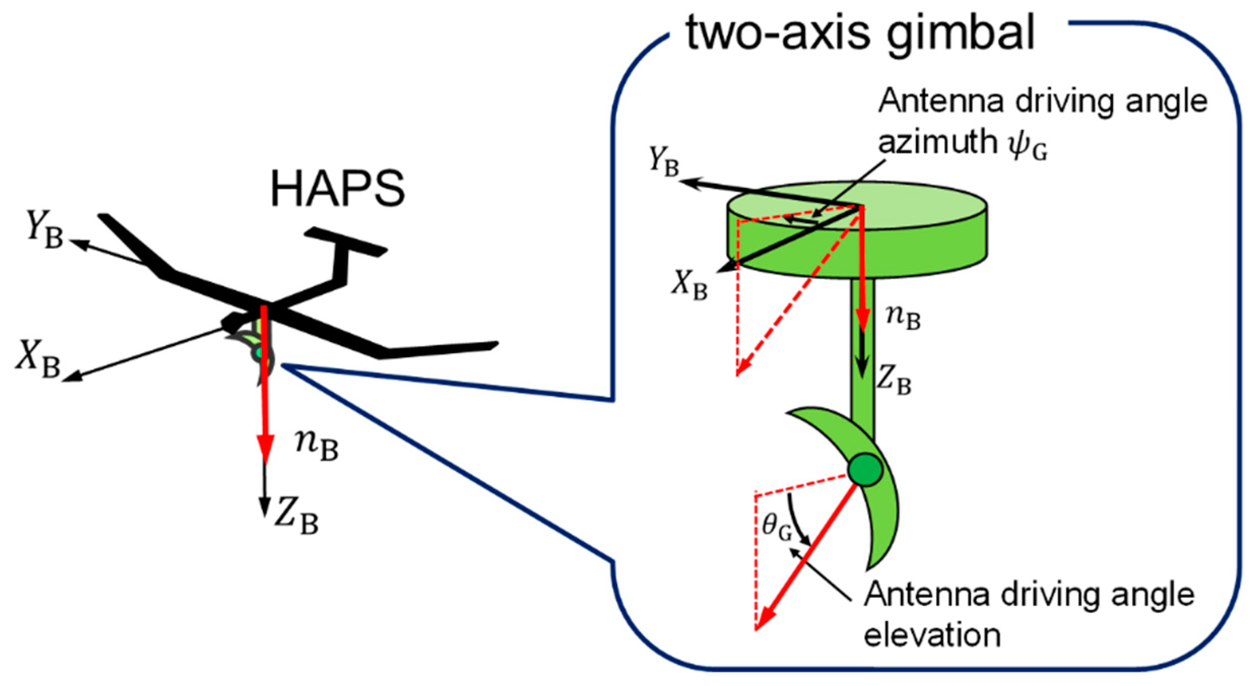
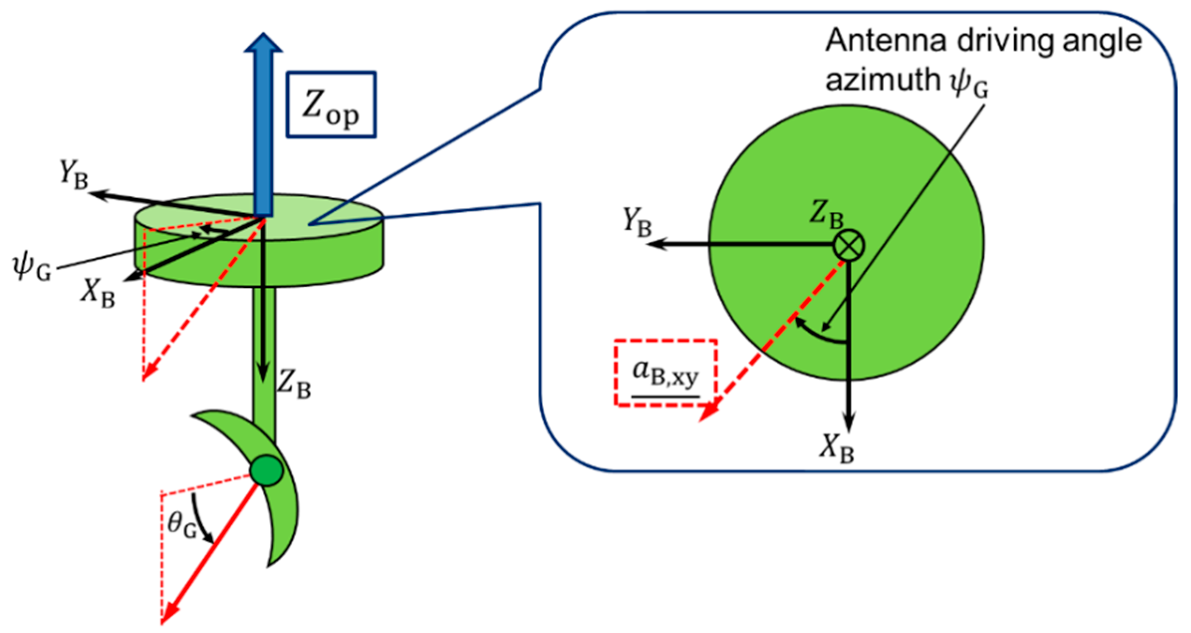
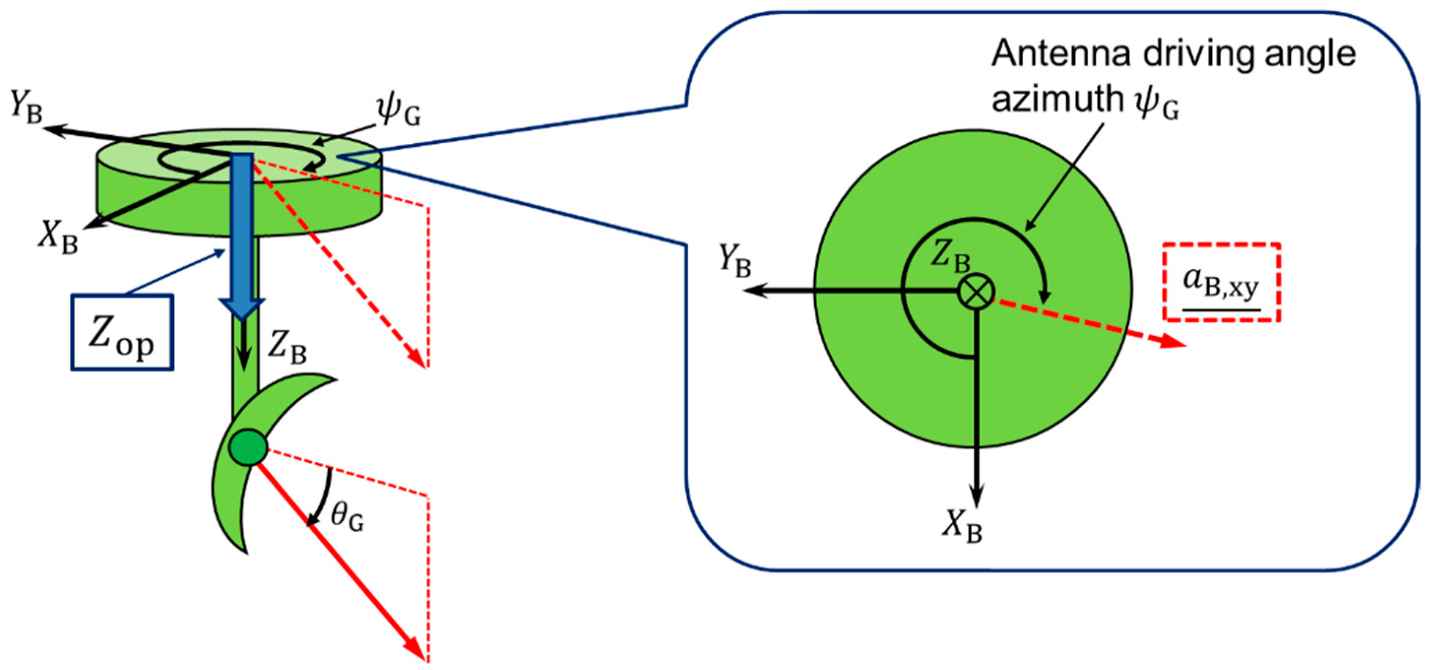
2. The Antenna Pointing Control System
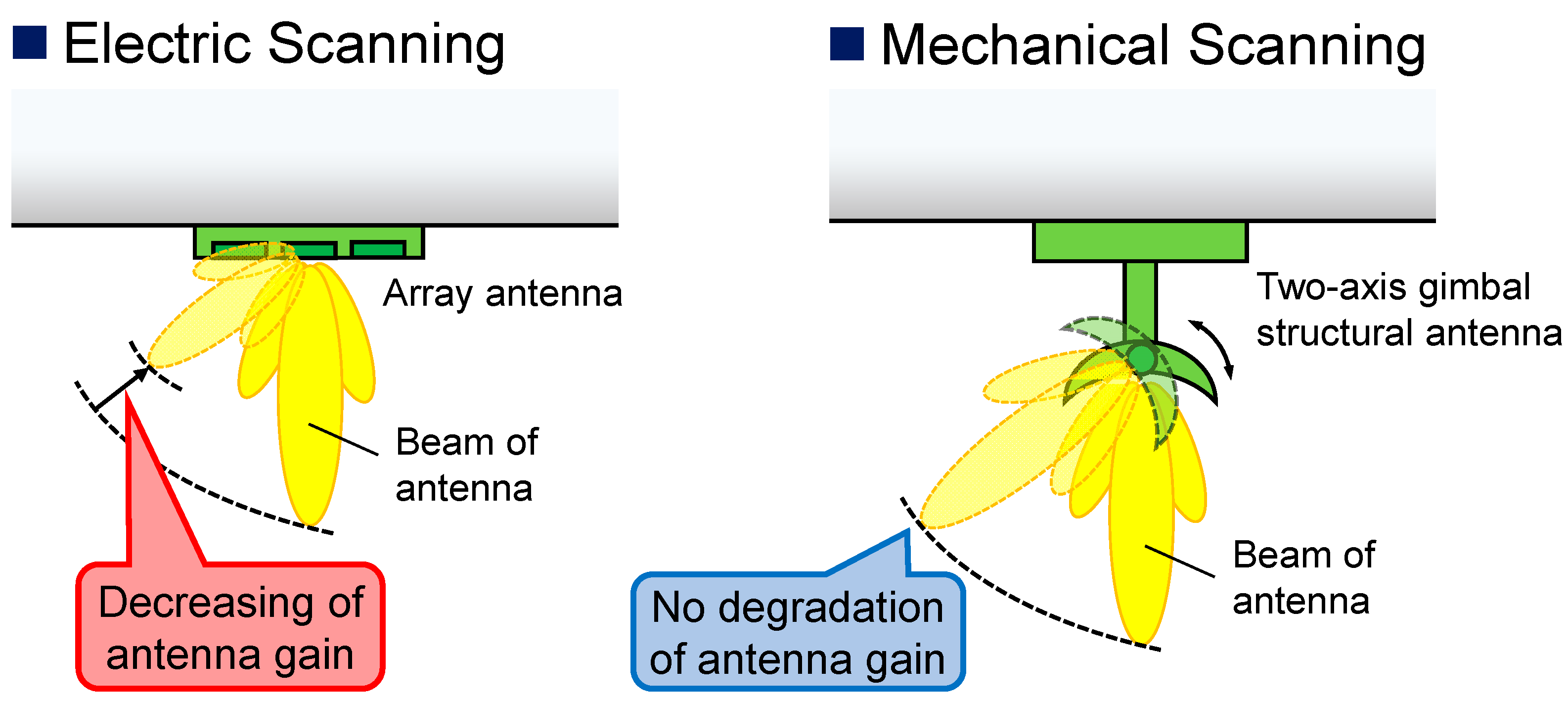
2.1. Mechanical Antenna Pointing Control
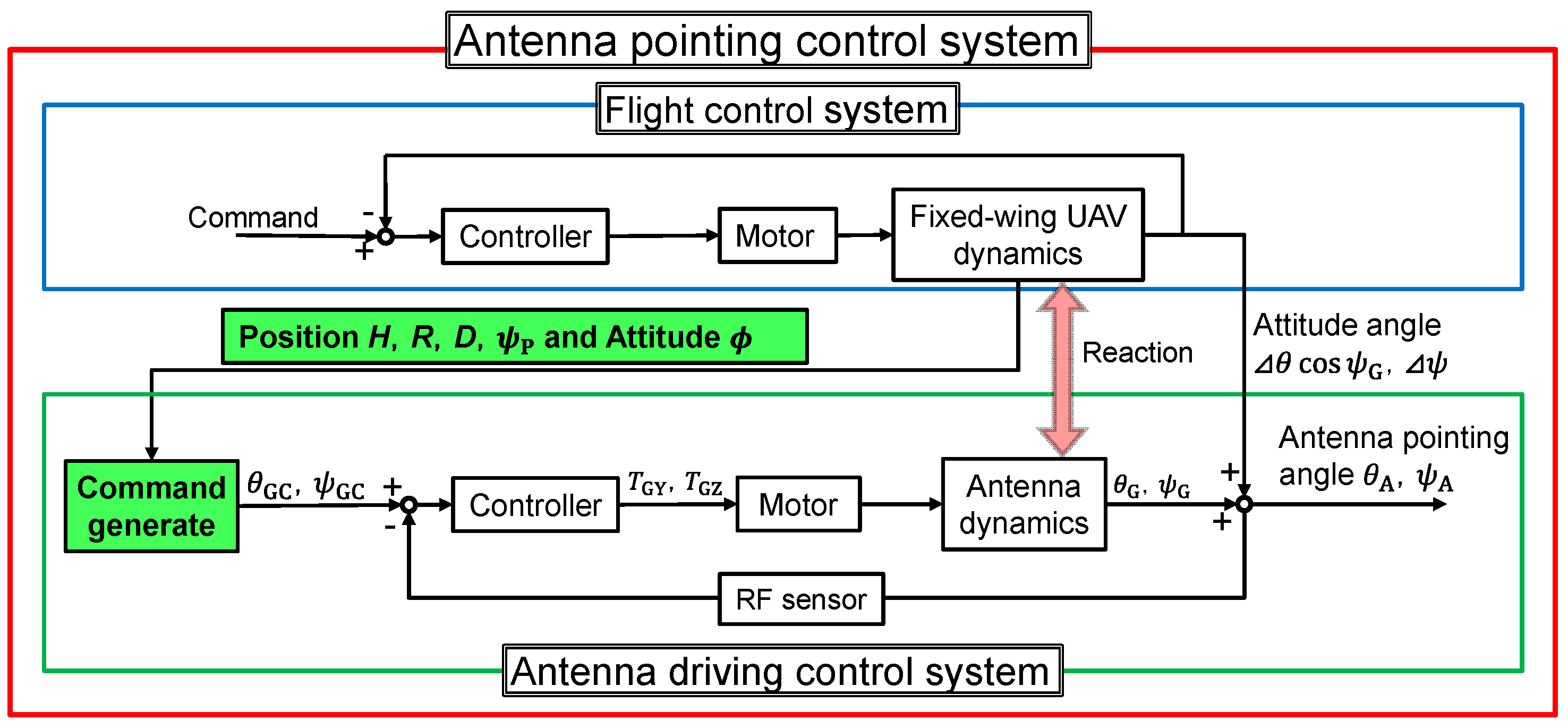
2.2. Proposed Antenna Pointing Control System
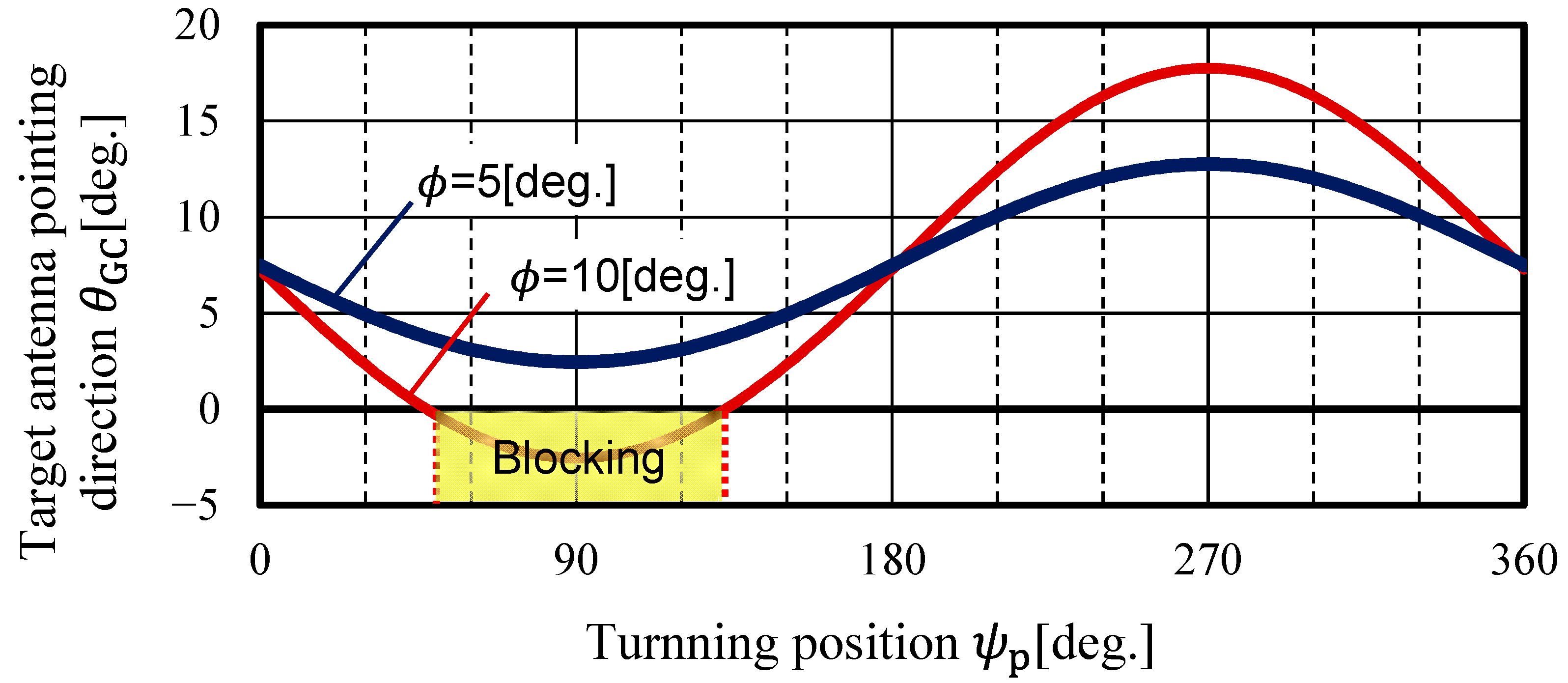
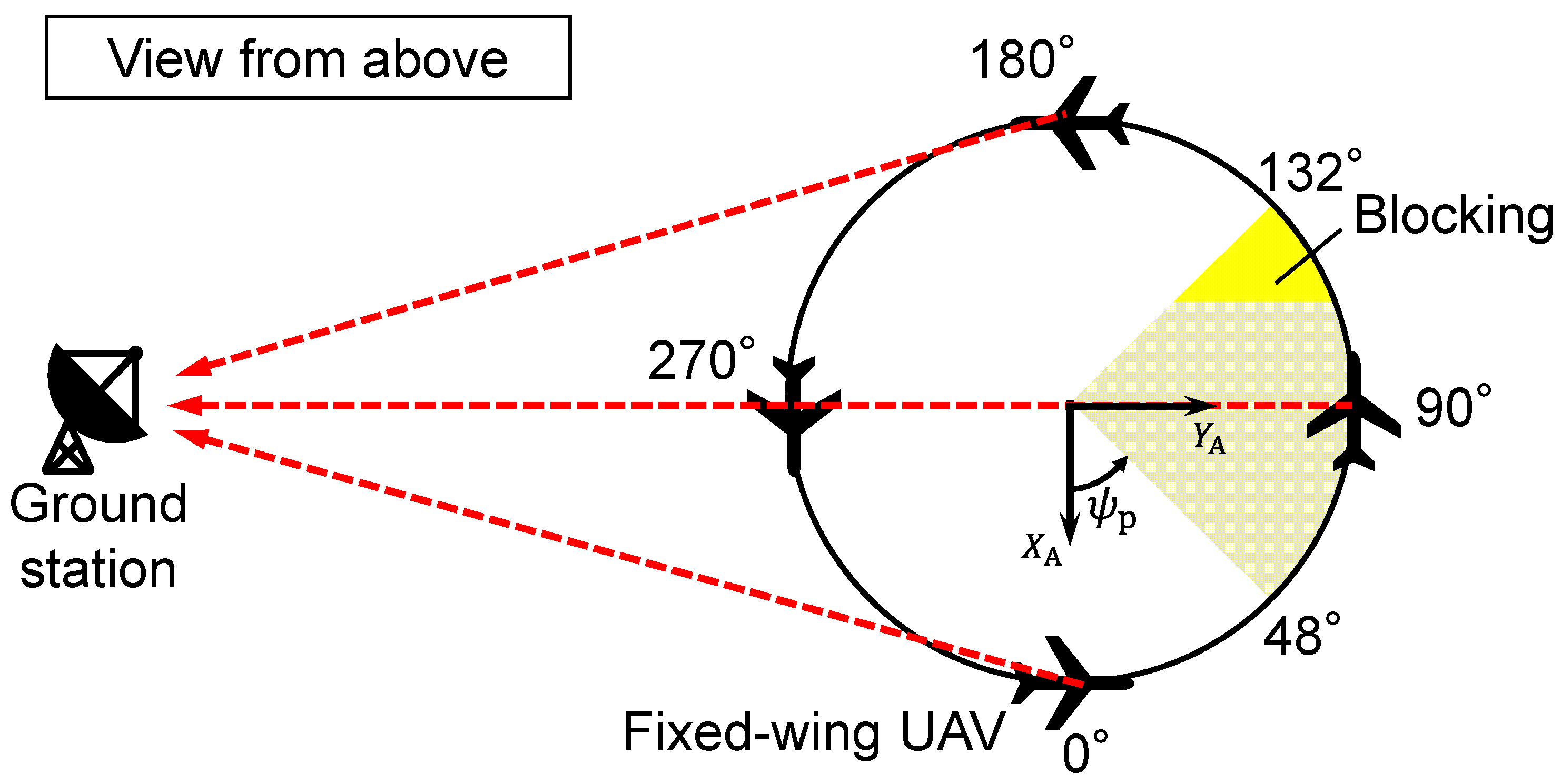
3. Antenna Pointing Direction and Its Blockage by UAVs
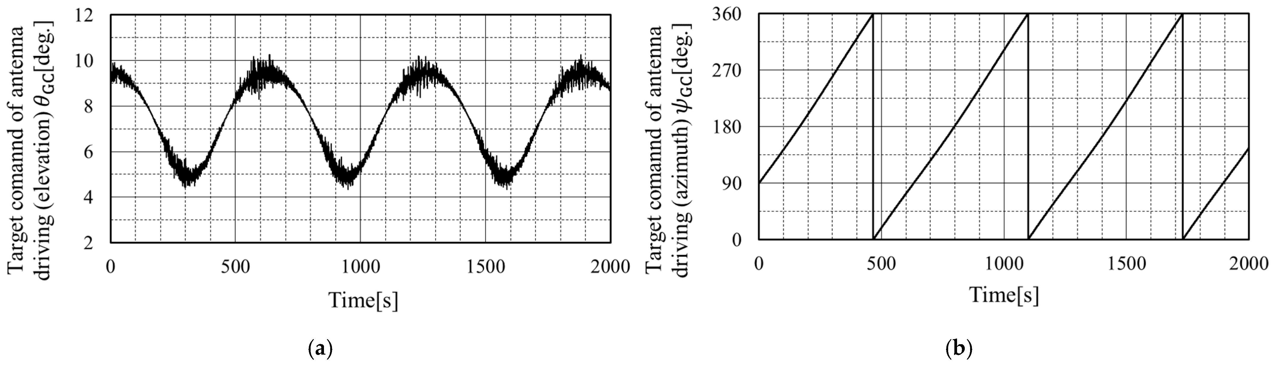
3.1. Target Commands of Antenna Driving Angle
3.2. Fluctuation of the Antenna’s Drive Angle due to Turning
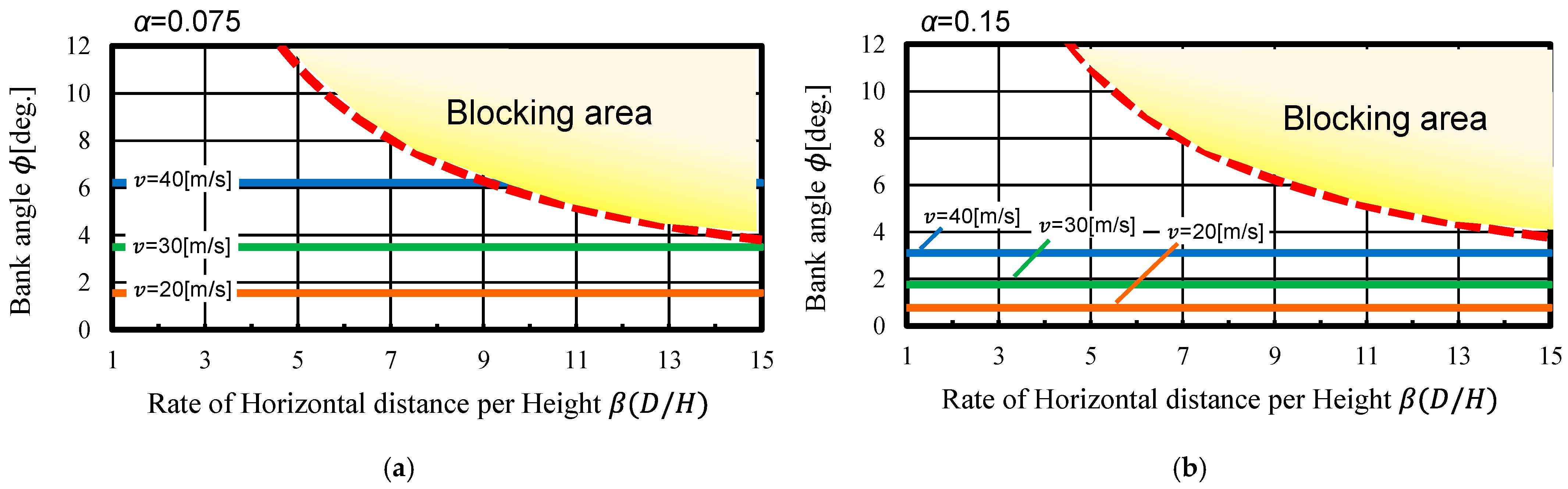
3.3. Roll Angle to Avoid Blocking
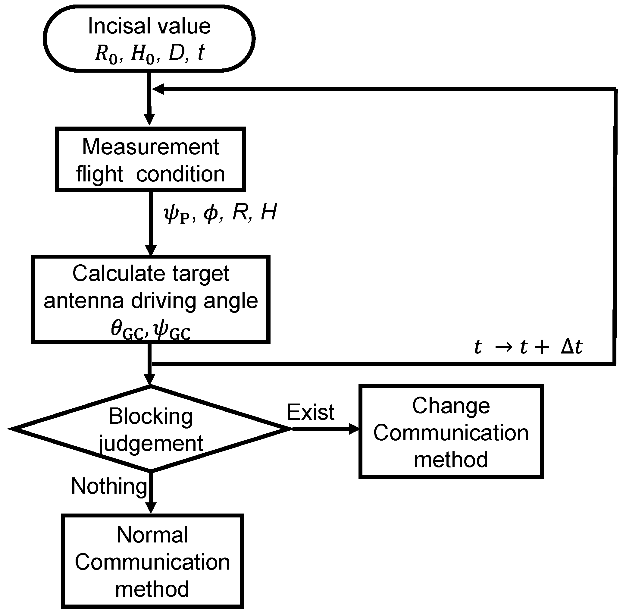
3.4. Blocking Judgement Flow
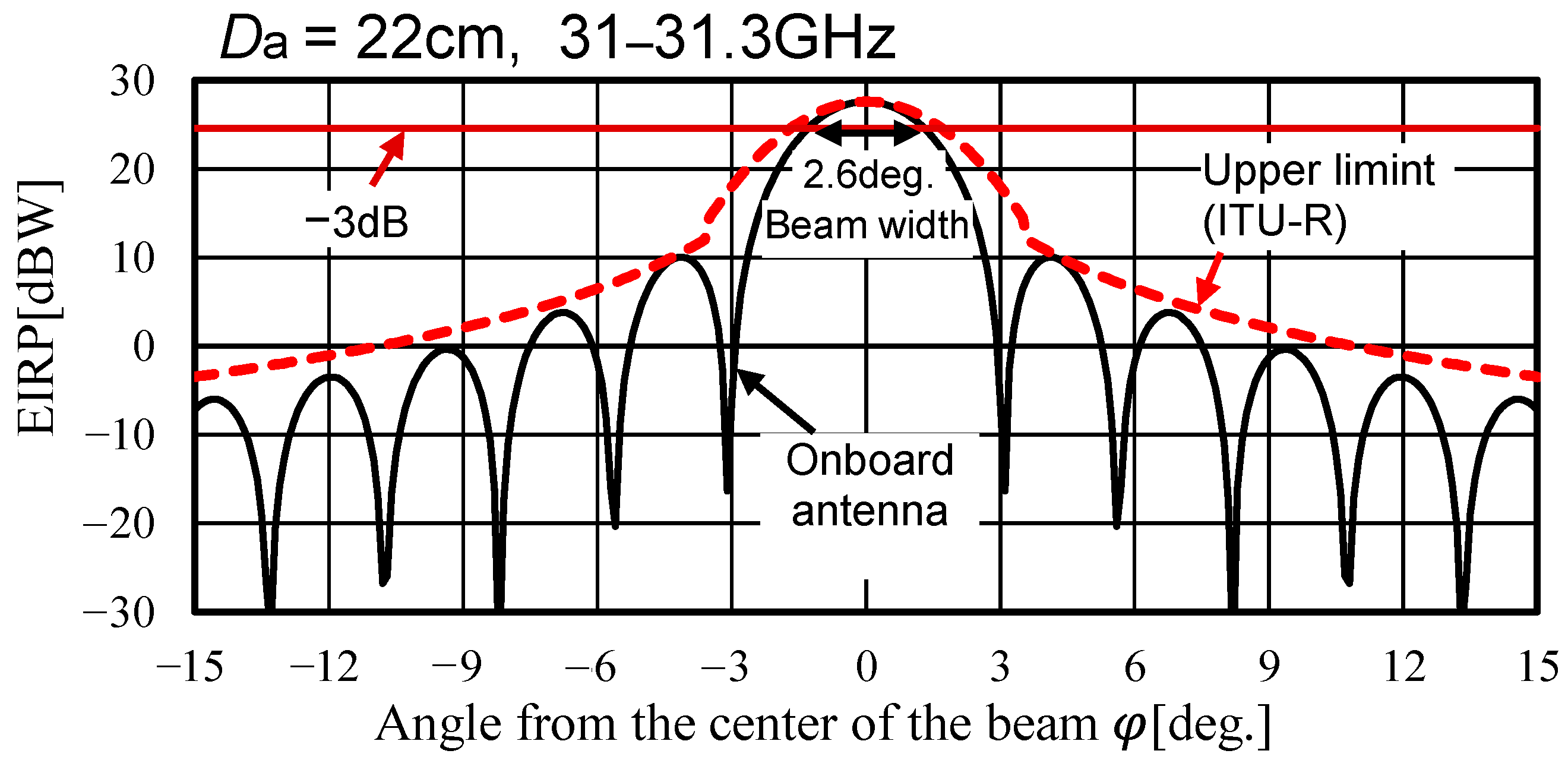
4. Size and Target Pointing Accuracy of Antennas
5. Design of the Antenna Pointing Control System
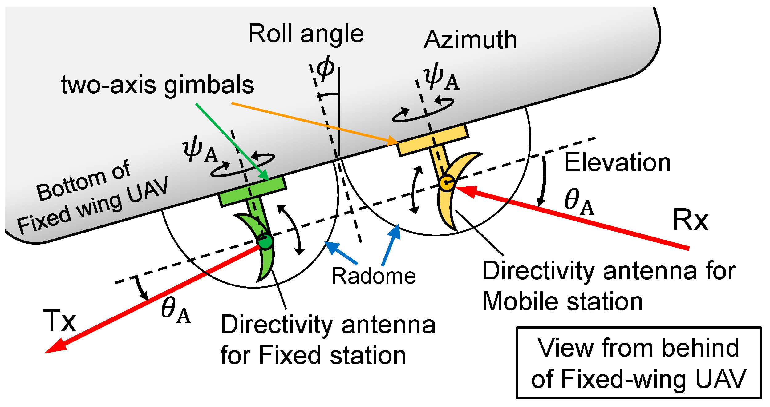
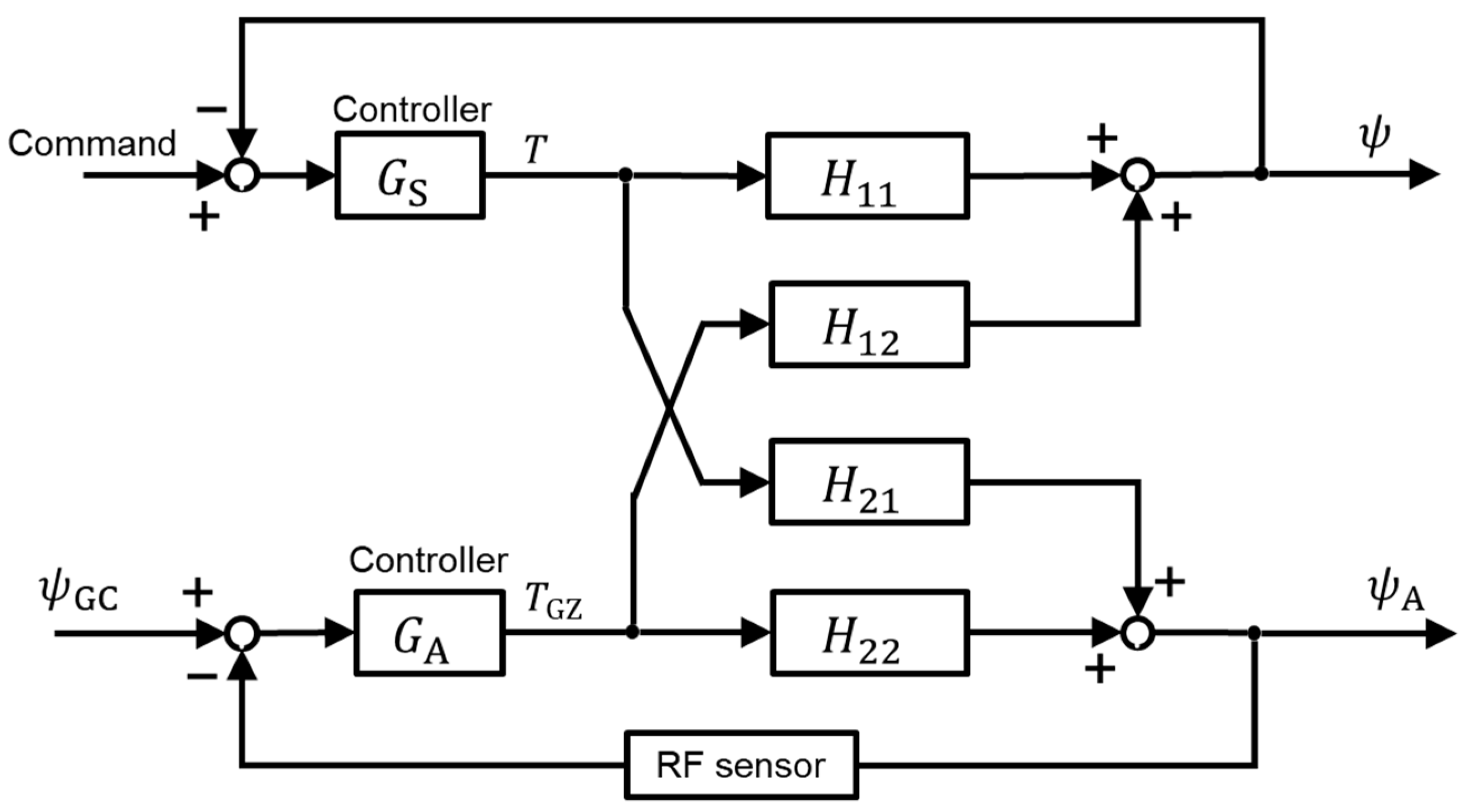
5.1. Configuration
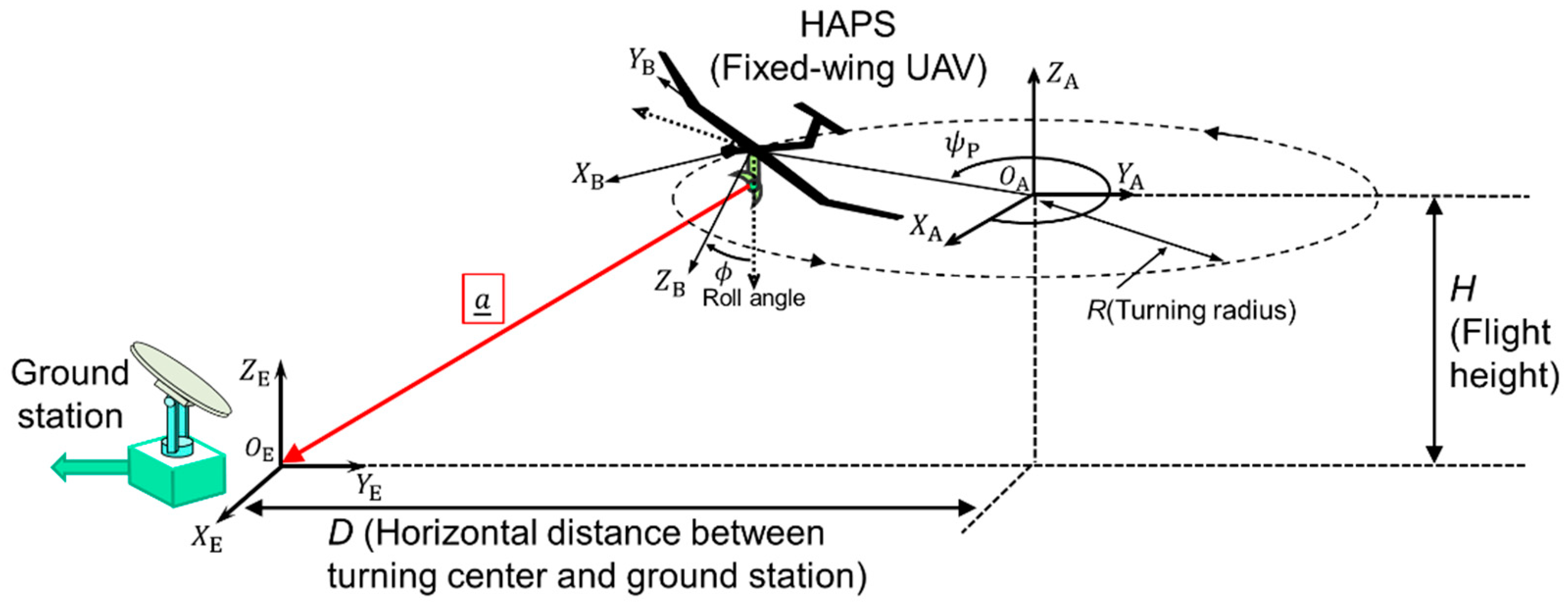
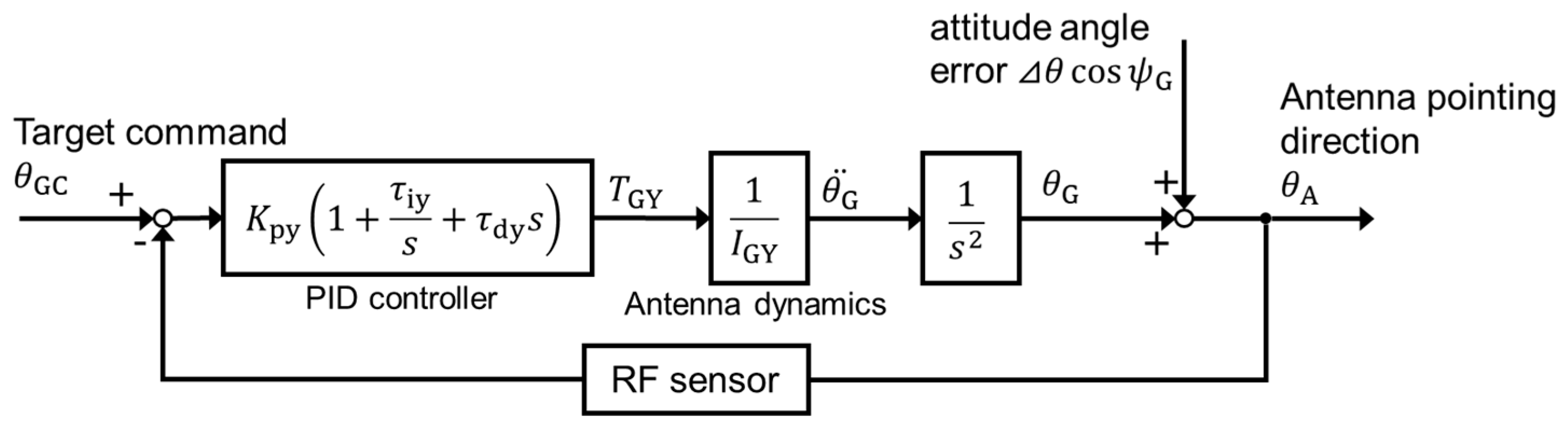
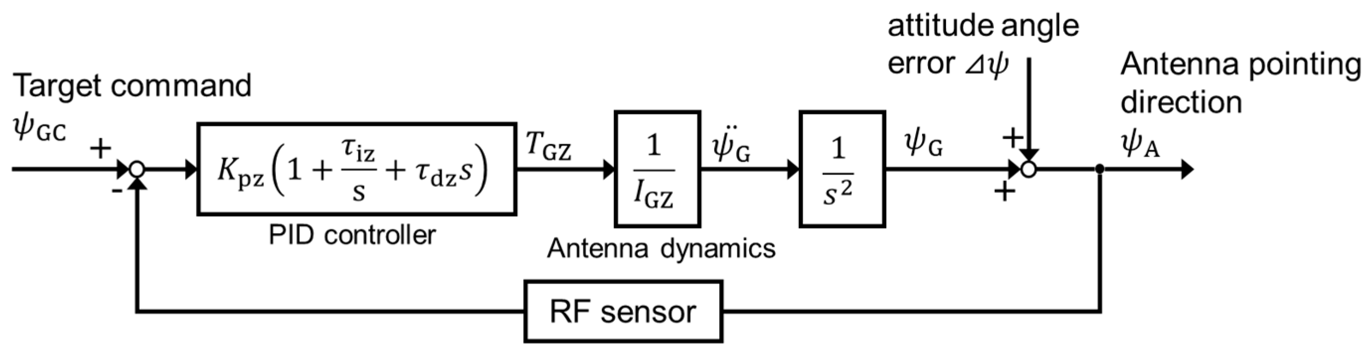
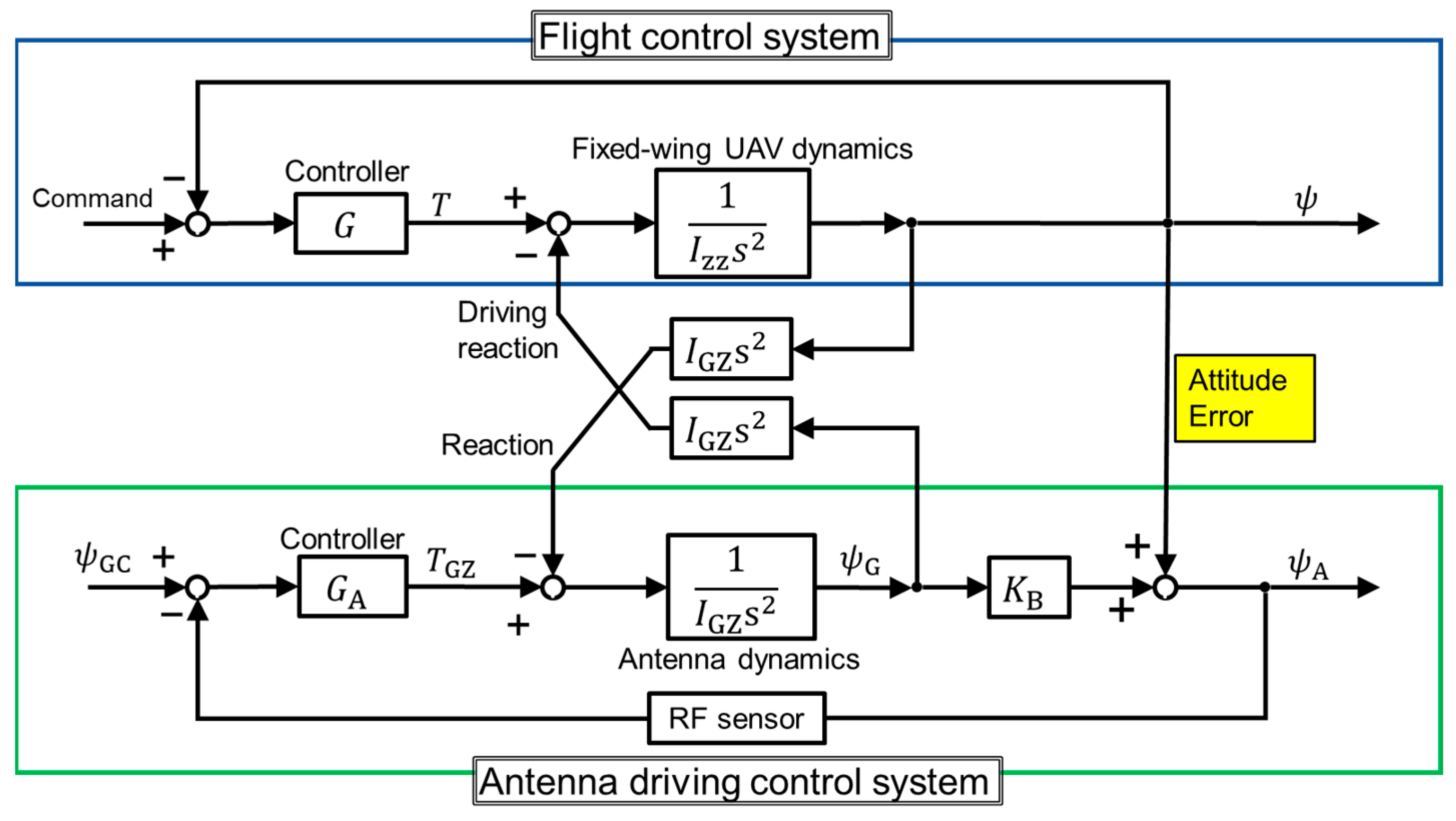
5.2. Equation of Motion for the Fixed-Wing UAV and Two-Axis Gimbals
5.3. Design
5.4. Control Frequency of Antenna Driving Control System
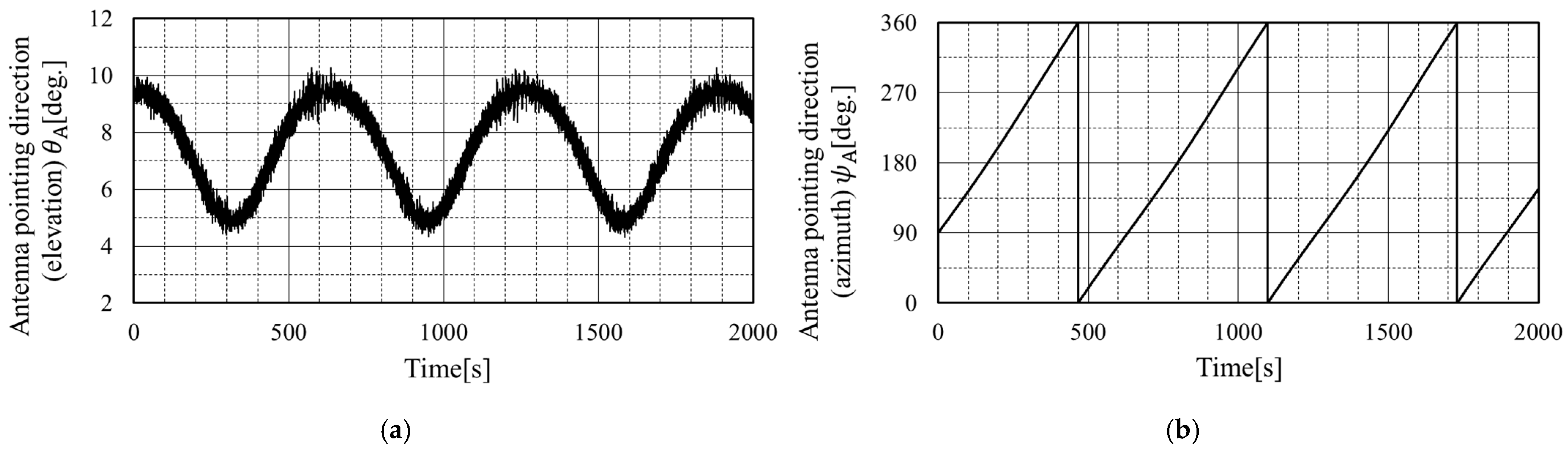
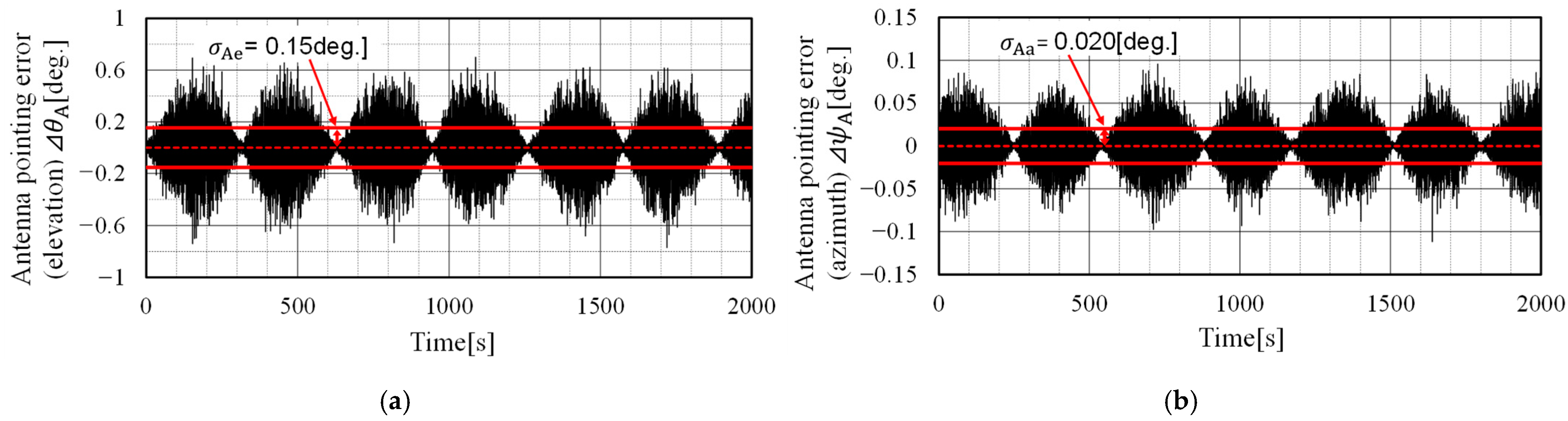
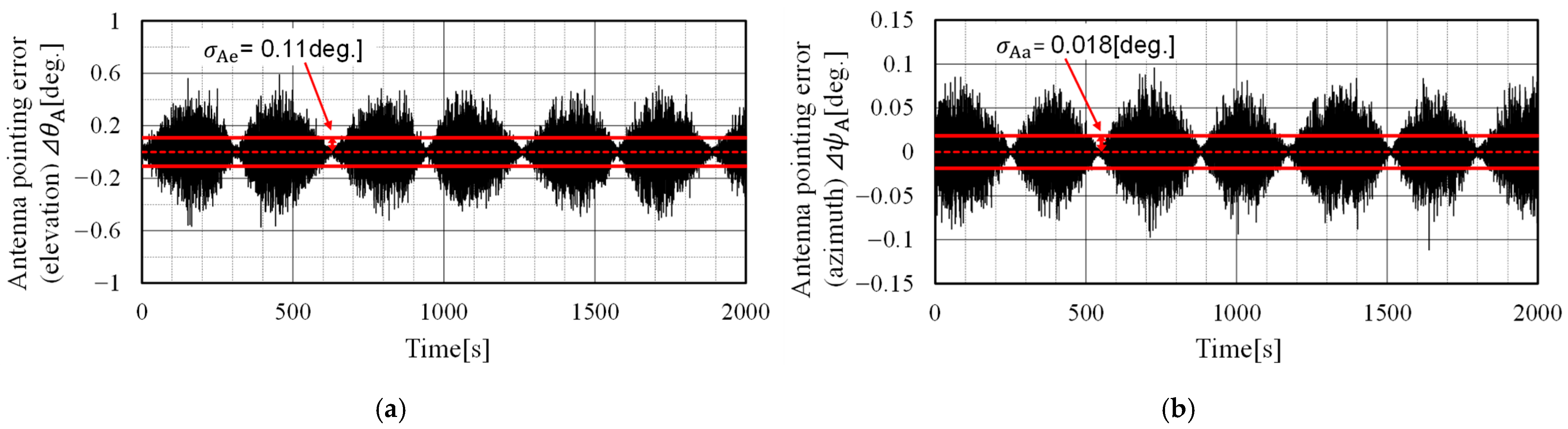
6. Evaluation of Antenna Pointing Control Error
6.1. Conditions
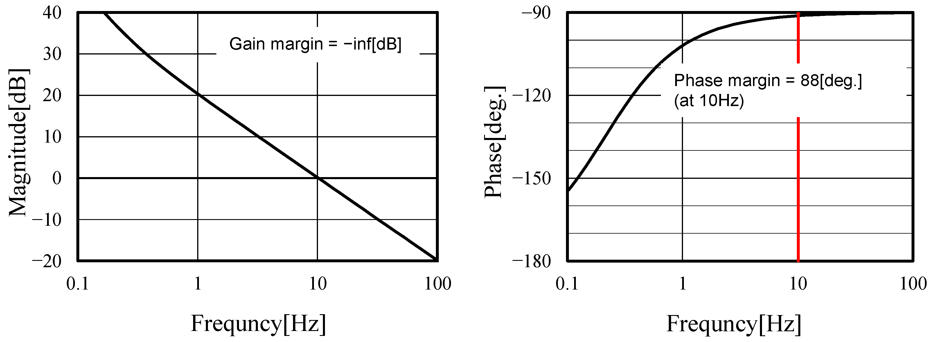
6.2. Stability Analysis
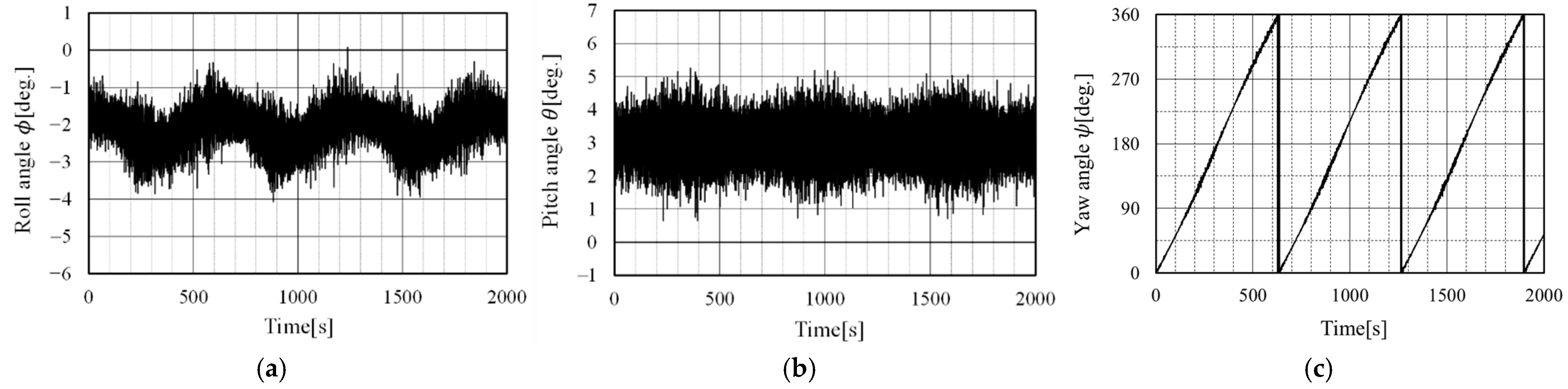
6.3. Results
7. Conclusions
Author Contributions
Funding
Data Availability Statement
Conflicts of Interest
Abbreviations
| vector of pointing | target turning flight velocity | ||
| horizontal distance | wind disturbance | ||
| antenna diameter | unit vector of UAV’s X-axis | ||
| control frequency of antenna drive | Z element of | ||
| H | flight altitude | ratio of radius and altitude | |
| the converted block elements | ratio of horizontal distance and altitude | ||
| moment or product of inertia | pitch angle of UAV attitude | ||
| ratio of fluctuation beam to drive | antenna pointing accuracy | ||
| L | moment of X body axis | elevation angle | |
| M | moment of Y body axis | control error of elevation | |
| N | moment of Z body axis | interference factor | |
| unit vector of UAV’s Z-axis | standard deviation of sensor noise | ||
| p | angular velocity of X axis | standard deviation of pointing error | |
| q | angular velocity of Y axis | roll angle of UAV attitude | |
| r | angular velocity of Z axis | yaw angle of UAV attitude | |
| R | turning radius | azimuth angle | |
| control torque of two-axis gimbal | control error of azimuth | ||
| turning flight velocity | angular velocity of UAV | ||
| Subscripts | |||
| A | antenna pointing | ||
| B | in the body frame coordinate | ||
| G | gimbal driving | ||
| GC | target command of gimbal driving | ||
| x, y, z | body axis or gimbal axis | ||
| 1, 2 | block number | ||
References
- Derek, K.; Randal, B.; Timothy, M.; Michael, L.; Wei, R. Autonomous Vehicle Technologies for Small Fixed-Wing UAVs. In Proceedings of the 2nd AIAA “Unmanned Unlimited” Systems, Technologies, and Operations, AIAA-2003-6559, San Diego, CA, USA, 15–18 September 2003. [Google Scholar]
- Masazumi, U.; Takuya, U. Study on Autonomous Flight Control for Tracking Meander Trajectory for Observation of Farm Land by Fixed-Wing UAV and Flight Verification. In Proceedings of the 58th Aircraft Symposium, JSASS-2020-5022, Online, Japan, 25–27 November 2020. (In Japanese). [Google Scholar]
- Piera, D.V.; Daniel, F.M.; Spada, R.R. HAPS Operations and Service Provision in Critical Scenarios. In Proceedings of the SpaceOps Conference, Marseille, France, 28 May–1 June 2018. [Google Scholar]
- Yunchou, X.; Frank, H.; Amitava, G.; Theodore, S.R. High Altitude Platform Stations (HAPS): Architecture and System Performance. In Proceedings of the 2021 IEEE 93rd Vehicular Technology Conference (VTC2021-Spring), Helsinki, Finland, 25–28 April 2021; pp. 1–6. [Google Scholar]
- Atsushi, N.; Kenji, H.; Yoshichica, O.; Hideki, O.; Hideki, H. HAPS Radio Repeater System Using the Same System as Terrestrial Mobile Communications System. In Proceedings of the 2018 IEICE Society Conference, B-5-37, Ishikawa, Japan, 11–14 September 2018. (In Japanese). [Google Scholar]
- Yohei, S.; Noboru, K.; Mitsukuni, K.; Kenji, H.; Yoshichika, O.; Atsushi, N. System Design of Gigabit HAPS Mobile Communication. IEEE Access 2020, 8, 157995–158007. [Google Scholar]
- Ryu, M.; Masayuki, O. R&D Program on Telecom and Broadcasting System Using High Altitude Platform Station. NICT 2001, 47, 4. [Google Scholar]
- Loh, Y.P. On antenna pointing control for communications satellite. In Proceedings of the 14th International Communication Satellite Systems Conference and Exhibit, AIAA-92-1940-CP, Washington, DC, USA, 22–26 March 1992. [Google Scholar]
- Robert, O.H.; John, M.L. Pointing performance of a Space Station Freedom Payload Pointing System. In Proceedings of the Guidance, Navigation and Control Conference, AIAA-90-3351-CP, Portland, OR, USA, 20–22 August 1990. [Google Scholar]
- Takanori, I.; Takeo, T.; Tetsuo, K.; Masakazu, A. Pointing Alignment Estimation for Precision Pointing Determination: Modeling, Estimation Method, and Calibration. In Proceedings of the AIAA Guidance, Navigation, and Control Conference, AIAA 2012-4784, Minneapolis, MN, USA, 13–16 August 2012. [Google Scholar]
- Laskin, R.A.; Sirlin, S.W. Future payload isolation and pointing system technology. J. Guid. Control Dyn. 1986, 9, 469–477. [Google Scholar] [CrossRef]
- Yohei, S.; Noboru, K.; Mitsukuni, K.; Kenji, H.; Yoshichika, O.; Atsushi, N. A System Design of Gigabit HAPS Mobile Communications with Energy Efficiency. IEICE Tech. Rep. 2019, 119, 359–364. [Google Scholar]
- Shoichi, S.; Yohei, S.; Koji, T.; Wataru, T.; Kenji, H. Demonstration of Footprint Fixation and Area Optimization Using a Prototype Cylindrical Array Antenna for HAPS Service Link. IEICE Tech. Rep. 2021, 121, 29–34. [Google Scholar]
- Morishige, H.; Hiroyuki, T.; Kouichi, M.; Moriyasu, M.; Yoji, A. Broadband Radio Communication System for Aircraft Using Millimeter-wave Band. Mitsubishi Denki Giho 2010, 84. (In Japanese) [Google Scholar]
- Hiroyuki, T.; Ryu, M.; Takuya, O.; Tomoshige, K.; Takashi, M.; Morio, T.; Jun, S.; Yoshihisa, K. Development of 38GHz-Band Wireless Communication System Using High Altitude Platform Station (HAPS) for 5G Network: Examination of the 38 GHz-Band Ground Station Antenna for HAPS. In Proceedings of the 2021 IEICE General Conference, B-3-4, Online, 9–12 March 2021. (In Japanese). [Google Scholar]
- Yuichi, T.; Yutaro, A.; Masazumi, U.; Shoichi, K.; Ken, H. Performance Evaluation Experiment of Highly Accurate and Responsive Tracking Antenna Control System for Simultaneous Observation by Unmanned Air Vehicles. In Proceedings of the IEICE Technical Report, SAT2016-66 (2017-02), Katsuura, Japan, 23–24 February 2017. (In Japanese). [Google Scholar]
- International Telecommunication Union. Report ITU-R F.2439-0; Electronic Publication: Geneva, Switzerland, November 2018. [Google Scholar]
- International Telecommunication Union. Recommendation ITU-R F.699-8; Electronic Publication: Geneva, Switzerland, January 2018. [Google Scholar]
- International Telecommunication Union. Recommendation ITU-R V.431-8; Electronic Publication: Geneva, Switzerland, August 2015. [Google Scholar]
- Broquet, J.; Claudinon, B.; Bousquet, A. Antenna pointing systems for large communications satellites. J. Guid. Control Dyn. 1985, 8, 71–77. [Google Scholar] [CrossRef]
- Hiroshi, H. Effect of Antenna Drives on Attitude Control Systems. Syst. Control Inf. 1988, 1, 137–143. (In Japanese) [Google Scholar]
- Yoichi, K.; Hiroshi, H.; Masazumi, U. Analysis of an Onboard Antenna Pointing Control System. J. Guid. Control Dyn. 1990, 13, 762–763. [Google Scholar]
- Mikihiko, M.J. Inst. Electr. Eng. Jpn. 2002, 12, 525–527. (In Japanese)


| Electrical Scanning | Mechanical Scanning | |
|---|---|---|
| Gain fluctuation | Large | Small |
| Pointing accuracy | Inverse proportional to number of arrays | Constant |
| Weight | Inverse proportional to pointing accuracy | Constant |
| Complexity | Proportional to number of arrays | Constant |
| 37.4 | ||
| 25.2 | ||
| 55.7 | ||
| 0.033 | ||
| 0.01 | ||
| 0.01 |
| - | 0.15 | |
| - | 7.5 | |
| [m/s] | 30 | |
| [m/s] | 10 |
| Attitude () | [deg.] | 0.5 |
| H | [m] | 0.2 |
| RF sensor | [deg.] | 0.1, 0.05, 0.01 |
| [m/s] | 0.17 | |
| GPS position | [m] | 1 |
Disclaimer/Publisher’s Note: The statements, opinions and data contained in all publications are solely those of the individual author(s) and contributor(s) and not of MDPI and/or the editor(s). MDPI and/or the editor(s) disclaim responsibility for any injury to people or property resulting from any ideas, methods, instructions or products referred to in the content. |
© 2023 by the authors. Licensee MDPI, Basel, Switzerland. This article is an open access article distributed under the terms and conditions of the Creative Commons Attribution (CC BY) license (https://creativecommons.org/licenses/by/4.0/).
Share and Cite
Hamajima, K.; Yasukawa, K.; Ueba, M.; Kanou, H.; Matsui, M.; Abe, J.; Itokawa, K.; Yamashita, F. Design and Evaluation on Onboard Antenna Pointing Control System for a Wireless Relay System Using Fixed-Wing UAV. Aerospace 2023, 10, 323. https://doi.org/10.3390/aerospace10040323
Hamajima K, Yasukawa K, Ueba M, Kanou H, Matsui M, Abe J, Itokawa K, Yamashita F. Design and Evaluation on Onboard Antenna Pointing Control System for a Wireless Relay System Using Fixed-Wing UAV. Aerospace. 2023; 10(4):323. https://doi.org/10.3390/aerospace10040323
Chicago/Turabian StyleHamajima, Koki, Kei Yasukawa, Masazumi Ueba, Hisayoshi Kanou, Munehiro Matsui, Junichi Abe, Kiyohiko Itokawa, and Fumihiro Yamashita. 2023. "Design and Evaluation on Onboard Antenna Pointing Control System for a Wireless Relay System Using Fixed-Wing UAV" Aerospace 10, no. 4: 323. https://doi.org/10.3390/aerospace10040323