Article

Comprehensive Comparison of Different Integrated Thermal Protection Systems with Ablative Materials for Load-Bearing Components of Reusable Launch Vehicles

1
Institute for Structural Mechanics and Lighweight Design, RWTH Aachen University, Wüllnerstraße 7, 52062 Aachen, Germany
2
Faculty of Mechanical Engineering, RWTH Aachen University, Templergraben 55, 52062 Aachen, Germany
3
Pangea Aerospace S.L., Avinguda Número 1, 20, 08040 Barcelona, Spain
*
Author to whom correspondence should be addressed.
Aerospace 2023, 10(3), 319; https://doi.org/10.3390/aerospace10030319
Submission received: 31 January 2023 / Revised: 18 March 2023 / Accepted: 20 March 2023 / Published: 22 March 2023

Abstract

:
Economic viability of small launch vehicles, i.e., microlaunchers, is impaired by several factors, one of which is a higher dry to wet mass ratio as compared to conventional size launchers. Although reusability may reduce launch cost, it can drive dry and/or wet mass to unfeasibly high levels. In particular, for load-bearing components that are exposed to convective heating during the aerothermodynamic phase of the re-entry, the mass increase due to the presence of a thermal protection system (TPS) must be considered. Examples of such components are aerodynamic drag devices (ADDs), which are extended during the re-entry. These should withstand high mechanical loading, be thermally protected to avoid failure, and be reusable. Ablative materials can offer lightweight thermal protection, but they represent an add-on mass for the structure and they are rarely reusable. Similarly, TPS based on ceramic matrix composite (CMC) tiles represent an additional mass. To tackle this issue, so-called integrated thermal protection systems (ITPS) composed of CMC sandwich structures were introduced in the literature. The aim is to obtain a load-bearing structure that is at the same time the thermally protective layer. However, a comprehensive description of the real lightweight potential of such solutions compared to ablative materials with the corresponding sub-structures is, to the authors’ knowledge, not yet presented. Thus, based on the design of an ADD, this work aims to holistically describe such load bearing components and to compare different TPS solutions. Both thermal and preliminary mechanical designs are discussed. Additionally, a novel concept is proposed, which is based on the use of phase change materials (PCMs) embedded within a metallic sandwich structure with an additively manufactured lattice core. Such a solution can be beneficial due to the combination of both the high specific stiffness of lattice structures and the high mass-specific thermal energy storage potential of PCMs. The study is conducted with reference to the first stage of the microlauncher analysed within the European Horizon-2020 project named Recovery and Return To Base (RRTB).

1. Introduction

1.1. Context

Microlaunchers are considered a strategic asset to achieve high frequency, tailored access to space for small satellites [1]. The addition of first stage reusability lowers costs and improves business sustainability. However, the structural mass does not scale linearly with the launchers’ size, leading to microlaunchers having comparatively higher structural coefficients with respect to conventional launchers, such as Ariane 5, Soyuz, and Falcon 9 [2]. This affects the launchers’ performance and thus the economic viability. To address this challenge, novel lightweight solutions are required for primary structural components. Additionally, to reduce wet and dry mass as well as complexity, passive re-entry and landing concepts can be considered. This, among others, is the aim of the feasibility studies led within the framework of the research project “Recovery and Return To Base” (RRTB) funded through the European Horizon 2020 programme [3]. In particular, the project aims to perform a re-entry flight phase without the use of retro-propulsion to achieve deceleration. Four mechanically actuated aerodynamic drag devices (ADDs), as shown in Figure 1, are extended from the rocket body to achieve the desired ballistic coefficient and obtain a sufficient deceleration during the re-entry and descent flight phase.
The ADDs are extended before the beginning of the re-entry flight phase and are then exposed to high convective heat fluxes and high dynamic pressures. Similar drag devices were investigated in the European project RETALT for a conventional size reusable launcher. As described by Marwege et al. [4], the design was judged unfeasible because of excessive reaction forces and moments, which would have led to high structural mass of the components. Although similar issues are faced for the design of ADDs for the mission considered in the RRTB project, different sizes and different design methodologies allow for not excluding the concept a priori. The design of such components requires a holistic approach and is mainly influenced by the thermal protection system (TPS) design, the structural design, and the design of the extension mechanisms. Each element intrinsically influences the design of the others. This work concentrates on the design of the TPS and offers a consideration on lightweight design potential of different thermal protection solutions and their effect on the overall structural mass. In particular, ablative materials as well as integrated TPS (ITPS) solutions are considered. ITPSs are load bearing structures made of materials with a high operative temperature and a high thermal insulation capability. The geometry is designed to increase the thermal resistance and have a high specific stiffness, thus aiming to obtain holistic mass reductions.

1.2. Ablative and Integrated Thermal Protection Systems

Ablative materials represent a high TRL solution for medium to high heat fluxes, typical of a ballistic re-entry [5]. Due to the endothermic reactions that take place during ablation, such materials offer high mass-specific thermal protection properties when compared to TPS based on sensible heat storage, i.e., ceramic tiles. However, the obvious disadvantage is that ablative materials are intrinsically expendable. Thus, re-application or replacement of the entire structure is often necessary to achieve reusability of the component. Furthermore the ablative TPS represents a non load-bearing add-on to the structural mass.
Passive TPS based on tiles, often made of high temperature metallic alloys or ceramic matrix composites (CMCs), are commonly employed for reusable launch vehicles (RLVs) [6]. Their application is limited by the maximum operative temperature of the material, thermally induced stresses, and outward thermal deflection. As indicated by Dorsey et al. in [7] as well as by Le and Goo in [8,9], excessive deflection can cause transition from a laminar flow on the outer wall of the TPS to a turbulent one. This is correlated with an increase of the heat transfer coefficient between the wall and hot gas, which thus causes an increase in the convective heat flux that the TPS outer wall experiences. Such an increase is coupled to even higher deformations and stresses, which can lead to failure. In particular, as evidenced by Heidenreich et al. [10], the higher the maximum operative temperature is, the lower the specific tensile strength of the material. CMCs received increasing attention due to the relatively constant mechanical properties at different temperatures and for retaining the highest specific tensile strength at temperatures above 1000 ℃ ([10,11,12]). In parallel to such material development, several efforts were made by authors in the literature to obtain passive thermal protection systems with high thermal and mechanical load bearing capability. With this goal, Blosser et al. [13] and Fischer et al. [14] developed structures consisting of a metallic honeycomb sandwich (based on nickel-superalloys and gamma titanium-aluminide, respectively) on the outer surface and a fibrous insulation encapsulated between the sandwich and the vehicle interior.
Bapanapalli et al. [15] and Gogu et al. [16] first proposed the concept of an ITPS. It is based on a corrugated core sandwich panel, hosting a fibrous insulation within the webs. In recent years, several authors investigated the use of CMCs as a structural material for ITPS, with different core topologies [17]. Le et al. [18] indicated that the choice of a particular core topology and material combination is not trivial and depends on the thermal and mechanical load profiles, the specific mechanical properties of the material as a function of expected temperature, and the obtainable effective thermal conductivity.
The specific stiffness and strength of most materials decrease with increasing temperature. Although CMCs are suitable for operation at high temperature (above 1000 ℃), the specific mechanical properties are, in absolute terms, lower than the ones of high temperature alloys, i.e., Ni-based superalloys or titanium aluminides. Additionally, operation at high temperature, i.e., approaching the radiative equilibrium temperature at the outer face sheet, while reducing the sensibly stored thermal energy, is cause for high thermal gradients in the out-of-plane direction of the sandwich structure. These gradients, in turn, increase the thermally induced stresses with respect to operation at lower temperatures. Therefore, when considering load-bearing components that require a lightweight, reusable TPS, the choice of material and configuration is not trivial. For a load-bearing component, a reduction of the wall temperature can be beneficial by allowing the use of materials with high specific mechanical properties.

Use of Phase Change Materials for Integrated Thermal Protection Systems

In this perspective, latent heat storage, i.e., melting of a so-called phase change material (PCM), is more efficient than sensible storage in mass-specific terms. Indeed, the thermal mass required to store heat via phase change is lower than the one needed to sensibly store the same amount of energy. However, only few authors ([19,20]) have investigated the use of PCMs for TPS. As explained by Nazir et al. [21], encapsulation and thermal conductivity improvement of PCMs proved to be the main challenge hindering the widespread application of such materials.
Recent literature ([22,23]) introduced the use of additively manufactured lattice structures to address both issues. These cellular solids were found to deliver high effective thermal conductivity, improving the thermal energy storage capability of the material. Additionally, sandwich structures built with such lattice cores exhibit attractive specific mechanical properties, simplify the junction of the core with the face sheets, and allow for the reduction of issues related to delamination [24]. Due to these favorable thermal and mechanical properties, lattice core sandwich structures with embedded PCMs are attractive for use in load-bearing lightweight TPS.
To address the aforementioned challenges in ITPS design, considering both the thermal and the mechanical behaviour is of fundamental importance. Thus, in this work, we perform a comparison between the thermal response of the three introduced TPS concepts for use on the ADD of the RLV considered in the RRTB project:
  • A phenolic impregnated carbon ablator (PICA) ablative TPSis analysed by means of a solver based on the one-dimensional finite volume method. The thermal mass is optimised via a root finding algorithm.
  • The CMC-based ITPS is composed of a corrugated core sandwich structure made of C/SiC and Saffil® insulation. The aforementioned solver (with ablation terms deactivated) is used to analyse it. A constrained optimisation algorithm based on sequential least squares programming (SLSQP) implemented in Python® is used to optimise the core and face sheets geometry for minimal thermal mass.
  • The solution based on lattice core-PCM sandwich structures is analysed via implementing a homogenisation technique based on the semi-analytical model proposed by Hubert et al. [22] and on the application of mixture rules, as reported in [23]. The PCM behaviour is modelled with use of the apparent heat capacity method, implemented in COMSOL® Multiphysics.
After treatment of each concept’s thermal design, a preliminary structural design for each considered solution is described. In the end, a comprehensive evaluation of both the thermal response results and the associated mechanical design is given. The results are compared in terms of total mass.

2. Governing Equations

2.1. Ablation

The internal energy balance of the solid and pyrolysis gas takes the form of a classic conduction equation combined with a source term that arises from the pyrolysis gas flow:
t ρ C p T + · λ ¯ ¯ · T + · m ˙ g h g = 0
In this equation, t denotes time, ρ and C p the solid density and specific heat capacity, respectively, T the temperature, λ ¯ ¯ the thermal conductivity tensor, m ˙ g the area specific pyrolysis gas mass flow rate vector, and h g the enthalpy of pyrolysis gas.
If one assumes that a control volume V moves at speed v g r , through use of the Gauss’ theorem, one obtains [25]:
d d t V ρ C p T d V + A λ ¯ ¯ · T · d A + A m ˙ g h g · d A A ρ C p T v g r · d A = 0 .
The terms in Equation (2) can be interpreted as follows from left to right: time change in internal energy of the control volume, conductive heat flux, convective heat flux due to pyrolysis gas movement, and convective heat flux due to grid movement.
With reference to Figure 2, the one-dimensional energy balance can be written as:
d d t V ρ C p T d z + m ˙ g h g r i g h t m ˙ g h g l e f t + λ T z r i g h t λ T z l e f t ρ C p T u g r r i g h t + ρ C p T u g r l e f t = 0 ,
where z is a stationary coordinate and u g r is the grid velocity.
The rate of decomposition of the material is temperature-dependent and can be described via an Arrhenius equation:
d ρ i d t = c i ρ i ρ c , i ρ v , i ρ c , i n r , i e A i T .
As the material can be made of multiple components, the index i indicates the ith component with its own decomposition law; c is called the pre-exponential factor, ρ , ρ v , and ρ c the current, virgin, and char density, respectively, n r the reaction order, and A i the scaled activation energy. The density of the material is obtained via the weighted sum of each phase:
ρ = i = 1 N p Γ i ρ i ,
where i represents the considered phase, N p is the number of present phases, Γ i is the volume fraction of the ith phase, and ρ i is the density of the ith phase.
The virgin material is generally assumed to be impermeable, thus forcing all gas to leave through the outer surface [26]. All the material that did not remain solid, i.e., transitioning from virgin to char status, is in gaseous form. Thus, for an internal control volume, as depicted in Figure 2, the pyrolysis gas mass flux is related to the decomposition from virgin to charred material, described in Equation (4), via mass conservation:
m ˙ g z = d ρ d t = i Γ i d ρ i d t .
The char ablation needs to be considered in the mass conservation when considering a control volume that includes the receding surface. At the surface of the ablative thermal protection system, chemical reactions such as oxidation and nitridation take place [27]. Three components take part in this reaction:
  • The hot boundary layer gases of the flow,
  • The surface (mostly charred) solid material,
  • The pyrolysis gas emerging from the depths of the decomposing layer.
If chemical equilibrium is assumed, the products of the reaction and their associated properties such as enthalpy can be determined. Programs such as Mutation++ [27] or CEA [28] can compute this equilibrium by minimisation of Gibbs energy. As an input, the ratios of the three components listed above are needed. To obtain these, the mass flux of the charred material m ˙ c and pyrolysis gas at the wall m ˙ g , w are non-dimensionalised:
B c = m ˙ c ρ e u e C M
B g = m ˙ g , w ρ e u e C M ,
where ρ e and u e are the boundary layer edge gas density and velocity, respectively; C M is the local Stanton number for mass transfer. As a result of the surface chemistry calculation, one receives:
B c = f T w , B g , p
h w = f T w , B g , p ,
where T w is the wall temperature, h w the enthalpy of the gaseous surface reaction products, and p the pressure [29]. The enthalpy flux that is carried away from the material can then be calculated using ( m ˙ c + m ˙ g , w ) h w . The charred material mass flux m ˙ c can be connected to the surface recession rate s ˙ via:
m ˙ c = ρ w s ˙ ,
where ρ w is the density of the solid material at the wall.

2.2. Energy Equation for ITPS

For a passive, non-ablative TPS, the energy equation can be written as a special case of the already described one for an ablative material, in which ablation does not take place.
t ρ e f f C p e f f T + · λ ¯ ¯ e f f · T = 0 ,
where ρ e f f is the effective density of the material, C p e f f its effective specific heat capacity, and λ ¯ ¯ e f f is the effective thermal conductivity tensor. However, a special treatment is needed to describe the behaviour of the ITPS embedding a PCM. This is done by means of the apparent heat capacity formulation [30]. The term corresponding to the latent heat of fusion is included as an additional non-linear term in the definition of the heat capacity of the material:
ρ e f f C p e f f = H T = C e f f + L α l T ,
where C e f f is the actual heat capacity, H is the enthalpy, L is the PCM latent heat of fusion, and α l is the liquid fraction at the melting front.

2.3. Material Properties

In this section, the treatment for the material properties of each considered concept is described.

2.3.1. Ablative Material

Difficulties in the determination of the local material properties arise from the thermal properties of the ablative TPS that depend on the degree of char β . As the heat shield material decomposes, the material properties, such as thermal conductivity or heat capacity, change. One commonly used approach in literature [31,32] to model this change is to prescribe fully virgin and fully charred material properties and interpolate based on the weight fraction of virgin and charred material.
The extent of the decomposition reaction β can be calculated through
β = ρ v ρ ρ v ρ c ,
where v refers to the virgin and c to the charred material; β is therefore 0 when the whole material is virgin and 1 for a fully charred state. Because of the assumption that a denser material contributes to the material properties to a higher degree, the weight fraction w v of virgin material is introduced:
w v = ρ v ρ v ρ c 1 ρ c ρ = ρ v ρ ( 1 β ) .
The char weight fraction w c is then
w c = 1 w v = ρ c ρ β .
The heat capacity c p for instance is computed using:
c p ( T , w v ) = w v C p , v ( T ) + w c C p , c ( T ) = w v C p , v ( T ) + ( 1 w v ) C p , c ( T ) .

2.3.2. Corrugated Core ITPS

The three-dimensional structure of the ITPS sandwich cores is homogenised to allow a reduced treatment. A unit cell of a corrugated sandwich panel and its defining dimensions are sketched in Figure 3. The corrugated sandwich consists of a top face sheet (TFS) with thickness t T and a bottom face sheet (BFS) with thickness t B separated by the core thickness t C . These are connected by webs of thickness t W at an angle of corrugation Θ . The voids in-between are filled with a high temperature insulation material. The pattern repeats with multiples of the unit cell length 2 p .
Effective properties for the core are derived from rule of mixtures. As density is based on the volume fractions of the respective materials, a volume rule of mixtures is chosen for this property. In contrast, heat capacity is defined by the respective mass fractions, which leads to a mass rule of mixtures. The respective areas of web and filling are simply the volumes divided by the core thickness t C . As this factor is common to both volumes, there is no difference between areal and volumetric homogenisation for this case. Thus, homogenisation equations for effective specific heat capacity C p , e f f , effective density ρ e f f , and effective thermal conductivity λ e f f of the corrugated core are obtained as follows [16]:
C p , e f f = C p , W ρ W t W + C p , F ρ F ( p sin Θ t W ) p sin Θ
ρ e f f = ρ W V W + ρ F V F V C = ρ W t W + ρ F ( p sin Θ t W ) p sin Θ
λ e f f = λ W A W + λ F A F A C = λ W V W + λ F V F V C = λ W t W + λ F ( p sin Θ t W ) p sin Θ .
Here, the indices W and F refer to properties of the web and filling materials, respectively.

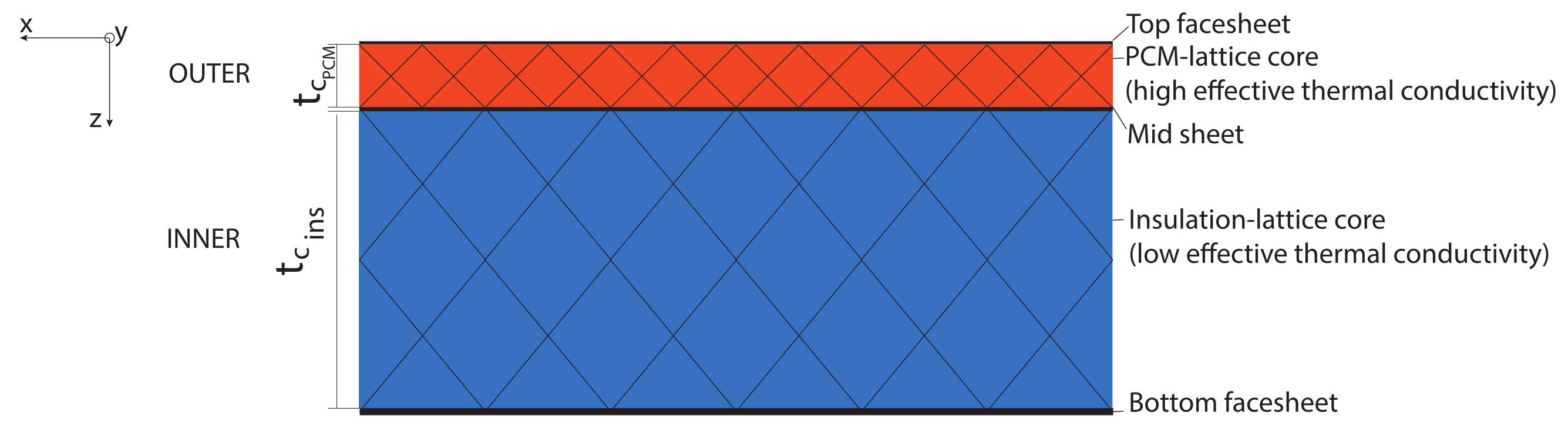
2.3.3. Lattice Core ITPS with Embedded PCM

Orthotropic cell geometry leads to an orthotropic effective thermal conductivity tensor of the composite. Several types of lattice cores exist. The ones most investigated in the literature are the cubic ones inspired by Bravais crystals; see Figure 4. Excluding the bcc cell, which exhibits an isotropic morphology, cubic arrangements of these cells exhibit orthotropic behaviour.
The effective thermal conductivity tensor must be written in the form
λ ¯ ¯ e f f = λ x y 0 0 0 λ x y 0 0 0 λ z ,
where x and y are the in-plane coordinates and z the out plane one in Figure 4, and the three-dimensional problem can be reduced to a two-dimensional one. The respective values for the thermal conductivity are obtained using a semi-analytical correlation for the definition of the relevant contributions in the equation, as according to Hubert et al. [22].
λ i = λ P C M ϵ + λ s G i ( 1 ϵ ) ,
where i indicates a generic principal direction, λ P C M is the thermal conductivity of the PCM, λ s is the thermal conductivity of the metallic lattice structure, G i is a dimensionless term that addresses the topology of the cell and is different for different directions, and ϵ is the porosity of the lattice structure. The effective density, effective specific heat, and effective latent heat of fusion can be easily obtained via the mixture rule as described in detail by Piacquadio et al. [23].

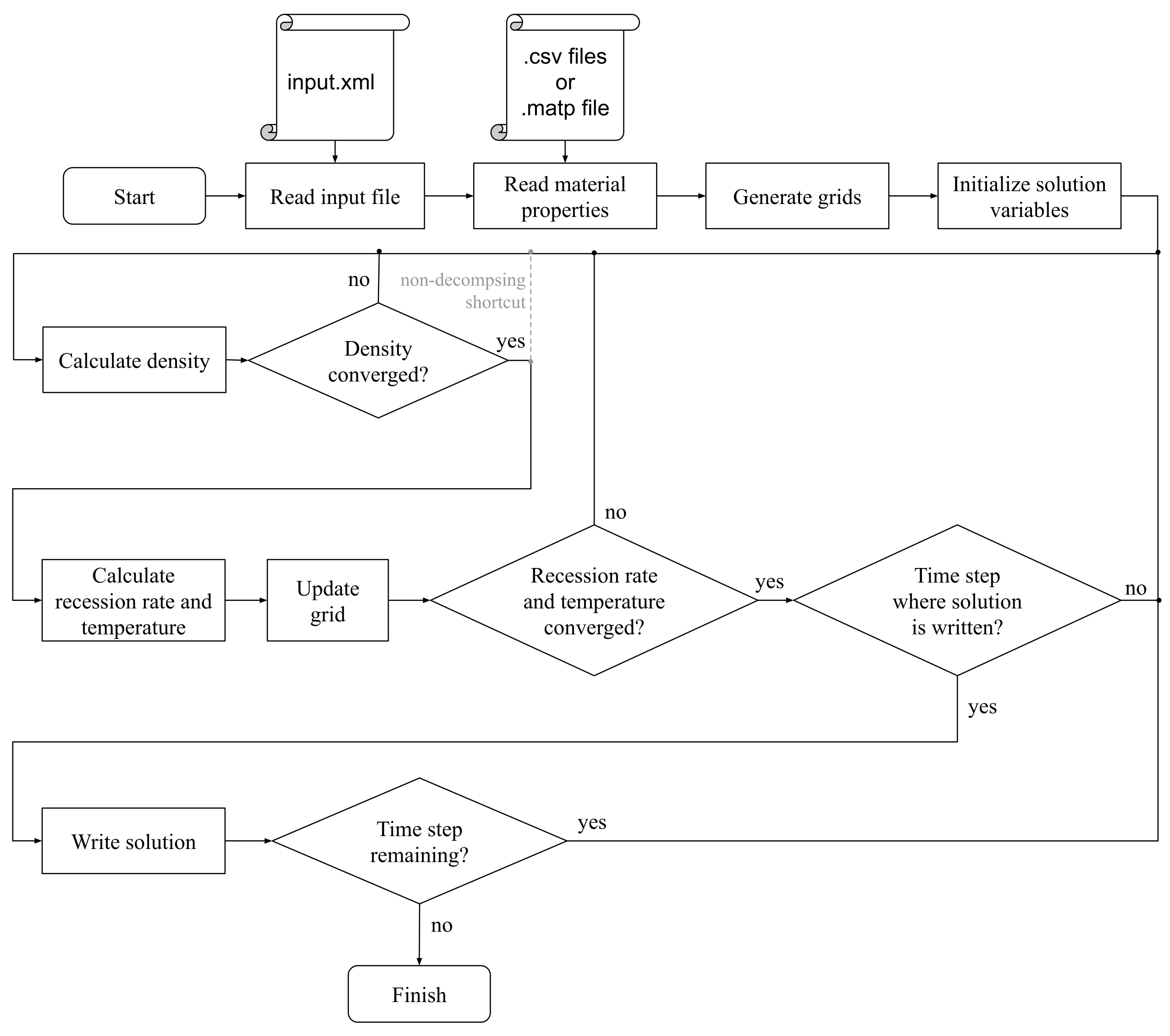
3. Solver for Ablative TPS and Corrugated Core ITPS
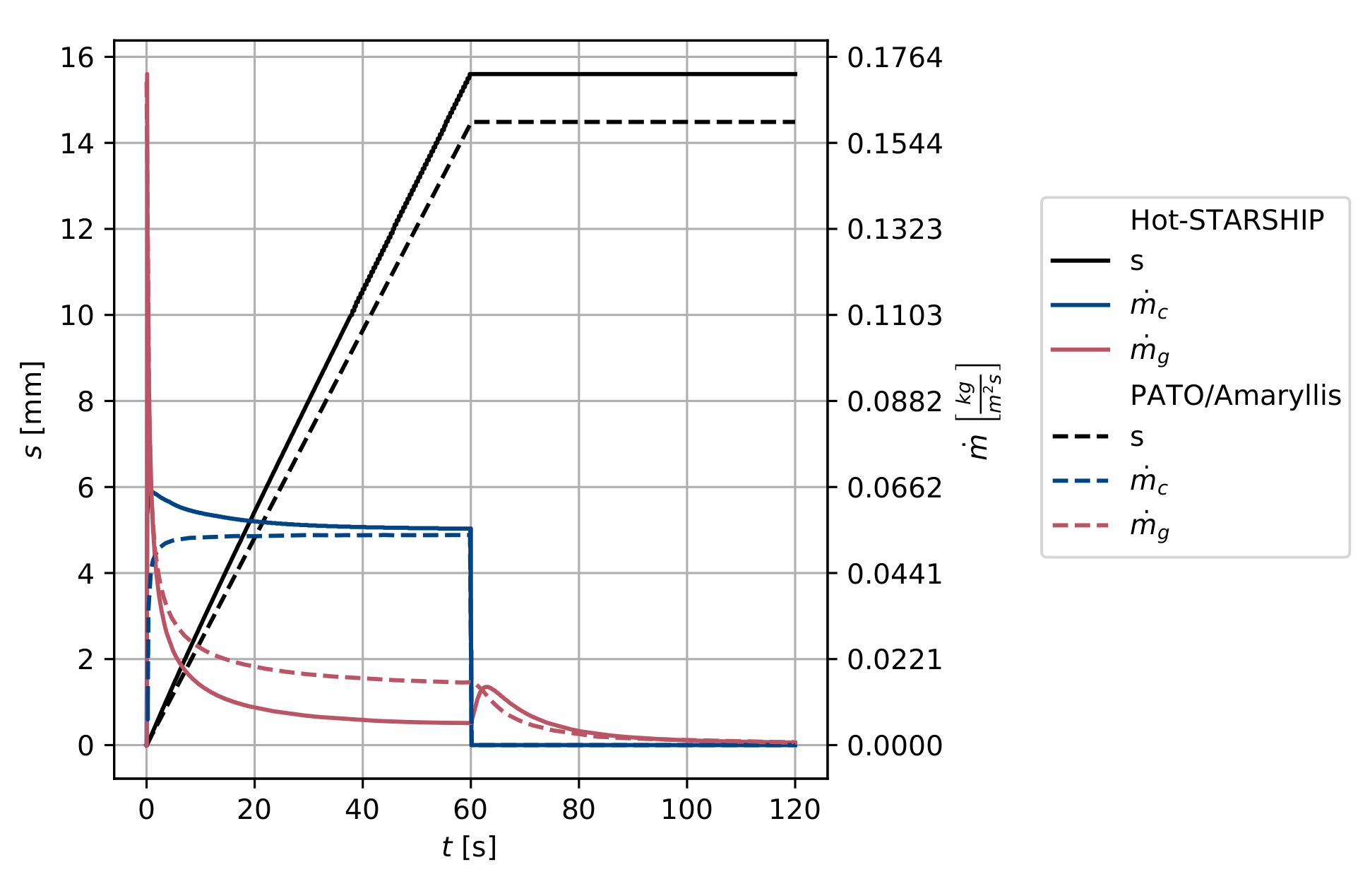
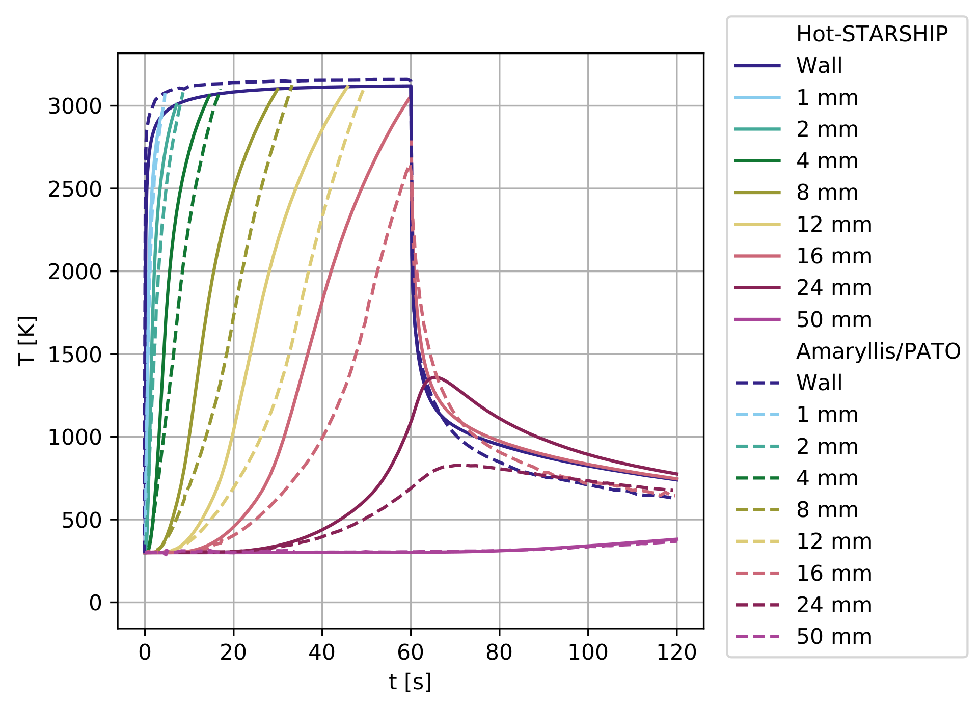
Using the governing equations described above, a software tool based on the finite volume method (FVM) for the calculation of the thermal response of both ablative and corrugated core ITPS is implemented in Python®. The implementation in Python® allows a simplified connection of the realised solver with different optimisation packages, which allow one to optimise the thermal mass. This way, an easy and accurate comparison of the two options is achievable. For this reason, the tool is named Hot-Structure and Ablative Reaction Shield Program (Hot-STARSHIP). Figure 5 shows a flowchart of the program.

3.1. Verification

To verify the accuracy of the solver, the solution for non-ablative and non-decomposing materials can be compared with available analytical solutions. The solver is able to accurately predict the thermal response of a passive TPS. The details of this verification procedure can be found in Appendix A. As there is no known analytical solution for the decomposing case, a comparison with other programs is performed. For this purpose, the theoretical ablative composite for open testing (TACOT) material is used, and the results presented by Lachaud et al. in [33] are used for verification. For the considered verification sample, a 7% higher recession was obtained by Hot-STARSHIP compared to the software presented in [33] (PATO or Amaryllis). The final difference between the results of the two solvers for the back-face temperature is about 12 K , and the average difference is even lower as the two curves cross each other (Appendix A, Figure A2). This is considered to be accurate enough for fast preliminary design purposes and for mass optimisation.

3.2. Optimisation

Due to its simplicity and the implementation in Python®, the Hot-STARSHIP solver can be easily connected to a constrained optimisation algorithm. The constraints are given via maximum achievable temperatures at the boundaries.
For the ablative material case, the constraint is given only by the maximum back-face temperature of the material. As this is in contact with the support structure, which is often made of carbon fibre-reinforced polymers (CFRP), the maximum temperature is set to 80 ℃. For the mass optimisation, in this case, it is sufficient and faster to solve a root-finding problem for the back-face temperature. As a thin TPS, while being lighter, will have higher back-face temperatures, the minimum mass, i.e., the minimum thickness t h , is the one that matches the maximum allowable back-face temperature. The root-finding problem can be expressed as:
Find th so that f ( t h ) = T 353.15 K = ! 0
where t h is the material thickness and T is the back-face temperature. As each function evaluation of f ( t h ) translates to a whole run of the transient solver, a fast convergence of the algorithm is key. As the function f ( t h ) is univariate, algorithm 748 from Python’s scipy package with a convergence order of 2.7 is chosen [34,35].
For the corrugated core ITPS, two temperature constraints must be fixed. The first one, i.e., TFS temperature, depends on the maximum operative temperature of the face sheet material. The second one, i.e., BFS temperature, is dependent on the underlying components. A common choice is to fix this to a maximum of 373 K (100 ℃). This work considers C/SiC based CMCs for the corrugated core ITPS. The maximum operative temperature is fixed at 1400 K. The geometric variables that influence the thermal response are fitted into a vector of variables x = [ t T , t C , t B , t W , p , Θ ] T , with reference to Figure 3. The minimisation problem then takes the following form:
min x f ( x ) with g ( x ) < 0
where f ( x ) is the function to be minimised and g is a vector-valued function of constraints. The function f can be written as:
f ( x ) = ρ T t T + ρ W t W + ρ F ( p sin Θ t W ) p sin Θ t C + ρ B t B
The constraint functions split the domain of x into a feasible range that fulfills the constraints function and an infeasible one.
g ( x ) = T B 373 K T m a x 1400 K < ! 0
For this study, the sequential least squares programming algorithm (SLSQP) from the Python® scipy package [36] is chosen. It has a high success rate up to problem dimensions of 20 compared to similar methods [37]. It is therefore well-suitable for the size of this problem.

4. Parametric Study of the Lattice Core-PCM ITPS

The use of a PCM is considered here to allow for a reduction of the wall temperature and thus the use of metallic alloys with high specific mechanical properties. The PCM should not be employed with a thermal insulation purpose as, in fact, a high thermal conductivity is needed to improve the thermal energy storage potential and thus reduce the wall temperature. The amount of PCM, i.e., the thickness of the lattice core, is directly related to the thermal response and is thus considered as a geometric parameter. To obtain thermal protection without mass increase, it is inefficient to consider a sandwich structure with a single core in which the PCM is embedded and for which the constraint is the same of a common ITPS, i.e., a maximum bottom face sheet temperature of 100 ℃. Exploiting the design flexibility offered by additive manufacturing, a multi-material, hierarchical sandwich structure, as schematically shown in Figure 6, made of two stacked sandwiches can be designed. In the outer sandwich core, the PCM is embedded, whereas the inner one has a thermal insulation functionality.
The considered material for the lattice structure in which the PCM is embedded is CuCr1Zr, a commonly used alloy for additively manufactured components in the aerospace field. The top face sheet is made of high temperature nickel alloy, i.e., Inconel®718. The center face sheet, lattice core of the insulation layer, and bottom face sheet are, for simplicity of treatment, considered to be made of Inconel 718 as well.
The different parts can be joined via brazing in different steps or via bi-metallic additive manufacturing. Several geometrical parameters influence the thermal performance of the structure, namely unit cell topology, unit cell size, strut radius, and porosity. For cubic unit cells, if the porosity, the unit cell, and the cell size are fixed, the strut radius is obtained as a dependent variable.
The results already present in the literature ([22,23]) allow for the reduction of the number of geometric parameters that must be varied to evaluate the thermal response of the lattice structure-PCM composite. Indeed, the f2ccz cell is consistently the unit cell that exhibits the highest out-of plane thermal conductivity for a given porosity. This is not true for the bcc unit cell, which shows the lowest thermal conductivity. Thus, the chosen unit cell topologies are trivially f2ccz for the PCM core and bcc for the insulation core. Similarly, the porosity of the lattice structure for the insulation core should be as high as possible to reduce both mass and effective thermal conductivity, thus leading to a trivial choice. The same is not true for the PCM core. The effective thermal conductivity should be high enough to improve the thermal energy storage of the PCM, but, as the conductivity increases with diminishing porosity, it should be kept as low as possible to keep mass at a minimum. For this reason, the porosity is varied in a range, as reported in Table 1. Similarly, the PCM core thickness defines the PCM mass available and thus the thermal response. This is therefore also a parameter to be varied in the study. The insulation core thickness is varied as well, as it influences the effective thermal resistance. The geometric parameters and their range are summarised in Table 1.
In addition to the geometrical parameters, the thermo-physical properties of the PCM should be considered. A comparably high thermal diffusivity is beneficial for obtaining a fast expansion of the melting front. However, this is not beneficial to the overall thermal protection purpose. Additionally, a material with comparably high latent heat of fusion should be chosen. The melting point also defines the thermal response of the structure. Finally, density of the material has an obvious influence on the lightweight potential of the component. Therefore, it is clear that the material choice does not have a trivial indication. The parametric study performed in this work includes a plausible domain of geometrical variables and and different materials. In particular, the PCMs listed in Table 2 are considered to cover a wide range of melting point, latent heat of fusion, and thermal diffusivity. The listed properties are considered at room temperature. The listed materials are all compatible with Inconel or materials with higher nobility.
The solution of the problem associated with the composite of metallic lattice core and embedded PCM is not implemented in Hot-STARSHIP. Instead, the commercial solver COMSOL® Multiphysics is used, which is based on the finite element method (FEM). It implements the apparent heat capacity method described in Section 2.2. The homogenisation approaches described in Section 2.3.3 are used for both the PCM and insulation core.

5. Results and Discussion

5.1. Boundary Conditions

The ADD is extended via a group of mechanisms with two anchoring points on the structure. One at the root, the other at half of the ADD’s longitudinal length, as schematically shown in Figure 7. Rigid body elements are used to connect the fixation points to the structure. All translational and two rotational degrees of freedom (DOFs) are restricted. Only the rotational DOF about the y-axis is not.
The input convective heat flux is obtained from the reference mission analysed in the Recovery and Return to Base project of the Horizon 2020 programme. In this work, the focus lies on the ADDs of the first stage analysed within the project.
During ascent, the four identical quarter shells (Figure 1) form a cylindrical shell and function together as primary structure of the launcher’s interstage. During atmospheric re-entry, the ADDs are extended to act as aerodynamic decelerators and therefore experience high mechanical and thermal loads.
Based on the re-entry mission analysis, computational fluid dynamic (CFD) simulations were performed to obtain the heat flux distribution on the rocket body at the point of maximum heat flux of the trajectory, which corresponds to an altitude of 35 km and MACH = 8 speed. To obtain the heat flux variation as a function of time, the trajectory data is analysed with the Sutton–Graves formula [38]. The heat flux distribution on the ADDs as a function of time and longitudinal position along the component is obtained via interpolation and is reported in Figure 8a. The time t = 0 corresponds to the moment of the point of the descent trajectory at which the input convective heat flux at stagnation point first reaches 1 kW/m2. In a similar way, the pressure distribution is obtained and is reported in Figure 8b.
The overall simulation time for the transient thermal analysis is 250 s. Although the convective heating approaches zero after approximately 100 s from the considered initial condition, additional simulation time is considered to take into account heat diffusion within the structure. Although, after the hypersonic and supersonic phases of the flight, convective cooling takes place on the body, the conservative assumption is made that only radiative cooling takes place. To simplify the representation of the thermal analysis, only a section of the ADD is considered in the following. The time curve corresponding to the local maximum of 400 kW/m2 at the longitudinal position of 2.2 m on the ADD is considered. The pressure distribution is applied on the whole component.
The thermal boundary conditions of the problem are schematically shown in Figure 9. It should be noted that the simulation of the ablative TPS differs from the ITPS cases because of the presence of blowing of the ablation products. The input convective heat flux is corrected via a blowing-corrected heat transfer coefficient, which is calculated as in [39]. The value for the term ρ e u e C H still needs to be assumed and is conservatively defined to be 0.3 as in [33]. The output radiative heat flux is obtained assuming heat transfer with the environment at room temperature. The emissivity of the TFS of the ITPS is assumed to be 0.8. The emissivity of the ablative material depends on the char grade and is obtained from empirical data implemented in the material model.

5.2. Thermal Response of the Ablative TPS

The analysed material is PICA [40]. It exhibits a low recession rate, however, it also has a relatively high thermal conductivity. The root finding algorithm described in Section 3 is used to obtain the minimal thickness of the material. Figure 10a shows the temperature evolution at different points within the material as a function of re-entry time. Figure 10b shows the recession as a function of re-entry time. In Figure 10a, z is considered the thickness coordinate, which is fixed in space, i.e., the origin lies on the outer edge of the virgin ablative material. For this reason, several temperature curves end abruptly, indicating that the material at the corresponding coordinate ablated away at the given time point. The recession s is obtained by the subtraction of the initial thickness of the virgin material and the position of the moving ablating surface, as shown in Figure 9. The minimum thickness obtained is 47 mm, and a recession of 14.3 mm takes place. The additional material that does not ablate until the end of re-entry is necessary to respect the imposed constraint at the back-face temperature. Due to the relatively high thermal conductivity of PICA, much more material is needed for a proper insulation. The areal weight is 10.75 kg/m2.

5.3. Thermal Response of the Corrugated Core ITPS

While the focus of this work aims at comparing ablative TPS with a novel ITPS based on metallic lattice core sandwich structures with PCMs embedded, the comparison with CMC-based corrugated ITPS is useful, as this technology is established in the literature. The considered structural material is an existing C/SiC composite obtained via chemical vapour infiltration whose properties are homogenised based on [10]. The thermal conductivity parallel to the fibre orientation is considered on the webs, whereas the one orthogonal to the fibre is considered for the face sheets. The filling material considered is the Saffil® fibrous insulation felt.
The SLSQP optimisation algorithm described in Section 3 is used to obtain the geometrical parameters of the component, which are reported in Table 3. The obtained overall areal weight is 23.7 kg/m2. Figure 11 shows the temperature evolution under the same boundary conditions previously analysed. It can be noticed that a thermal gradient of 1100 K is present between the top face sheet and the bottom face sheet. This indicates that the optimisation reached its goals, achieving a component with a very low effective thermal diffusivity. This allows the re-radiation of a wide amount of the convective heat input. This design is beneficial from the thermal protection design point of view. However, due to the combination of high stiffness of C/SiC and high thermal gradient, thermo-mechanical stresses can become a concern, given the low specific strength of CMCs.

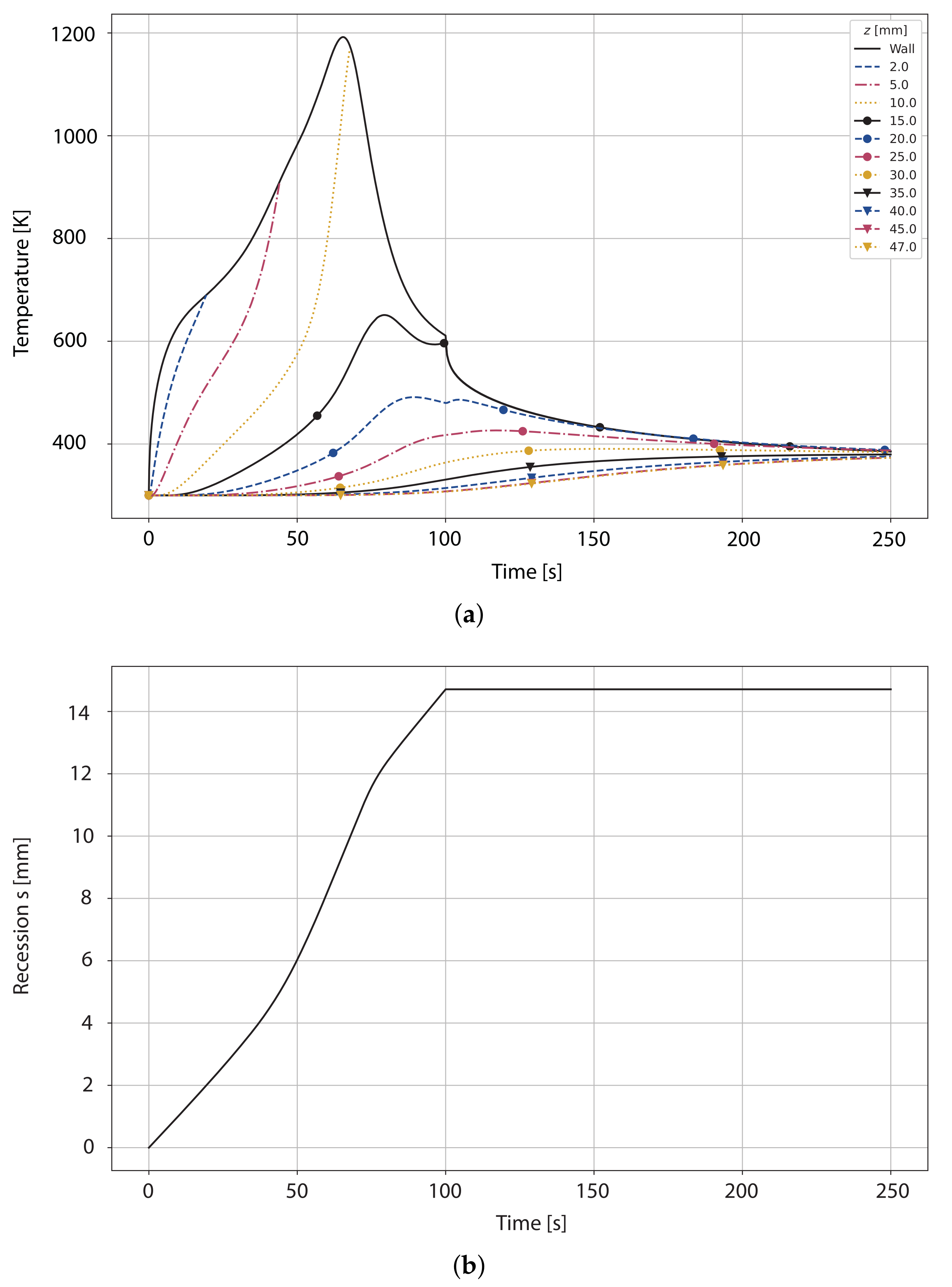
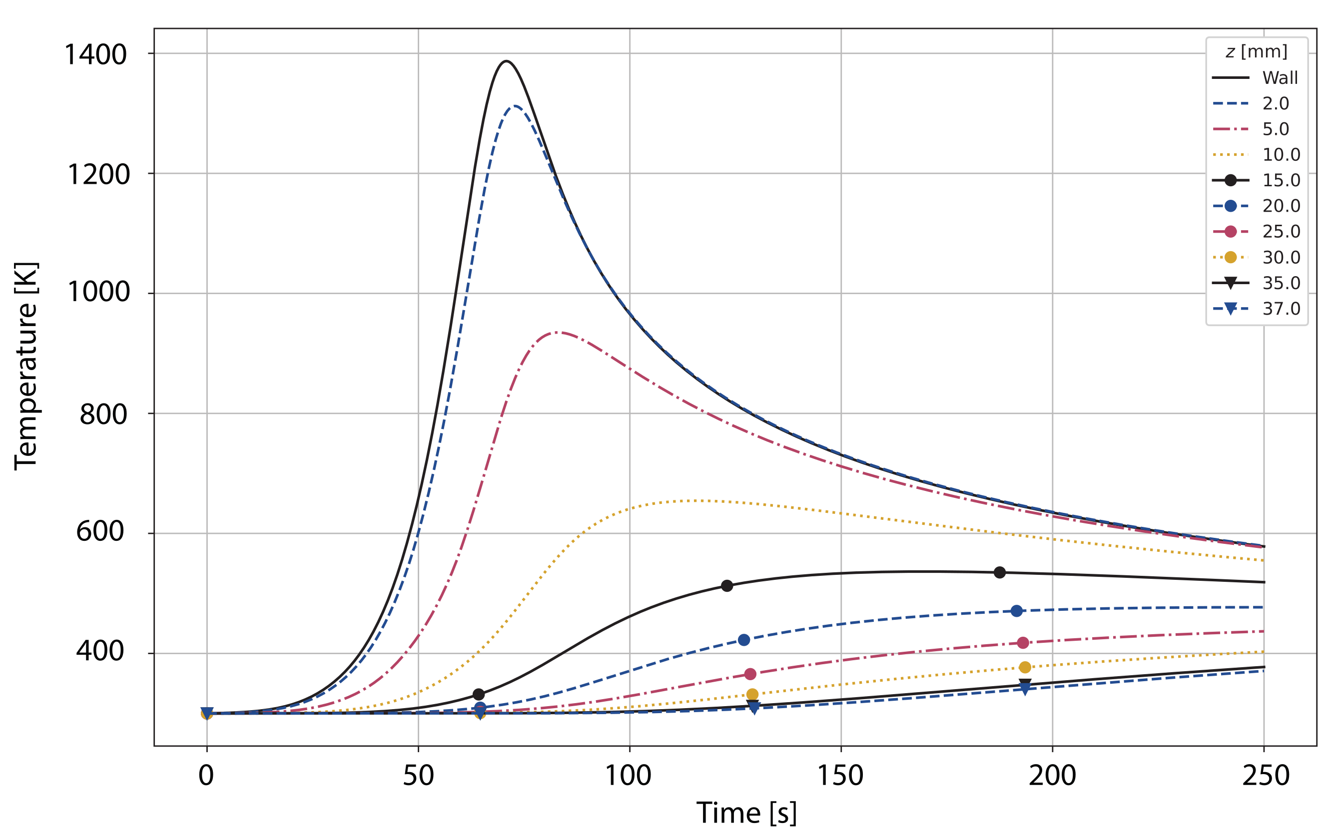
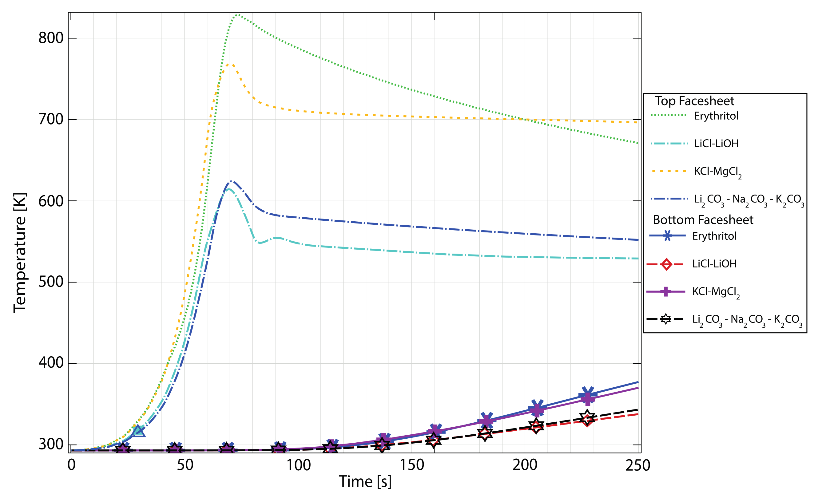
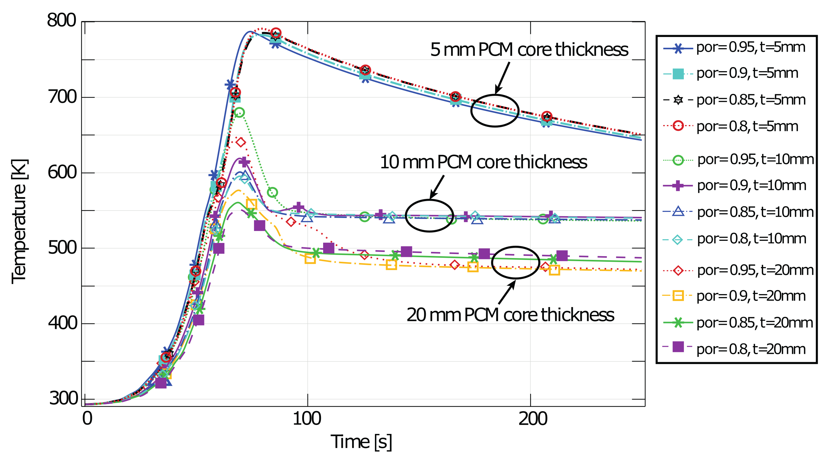
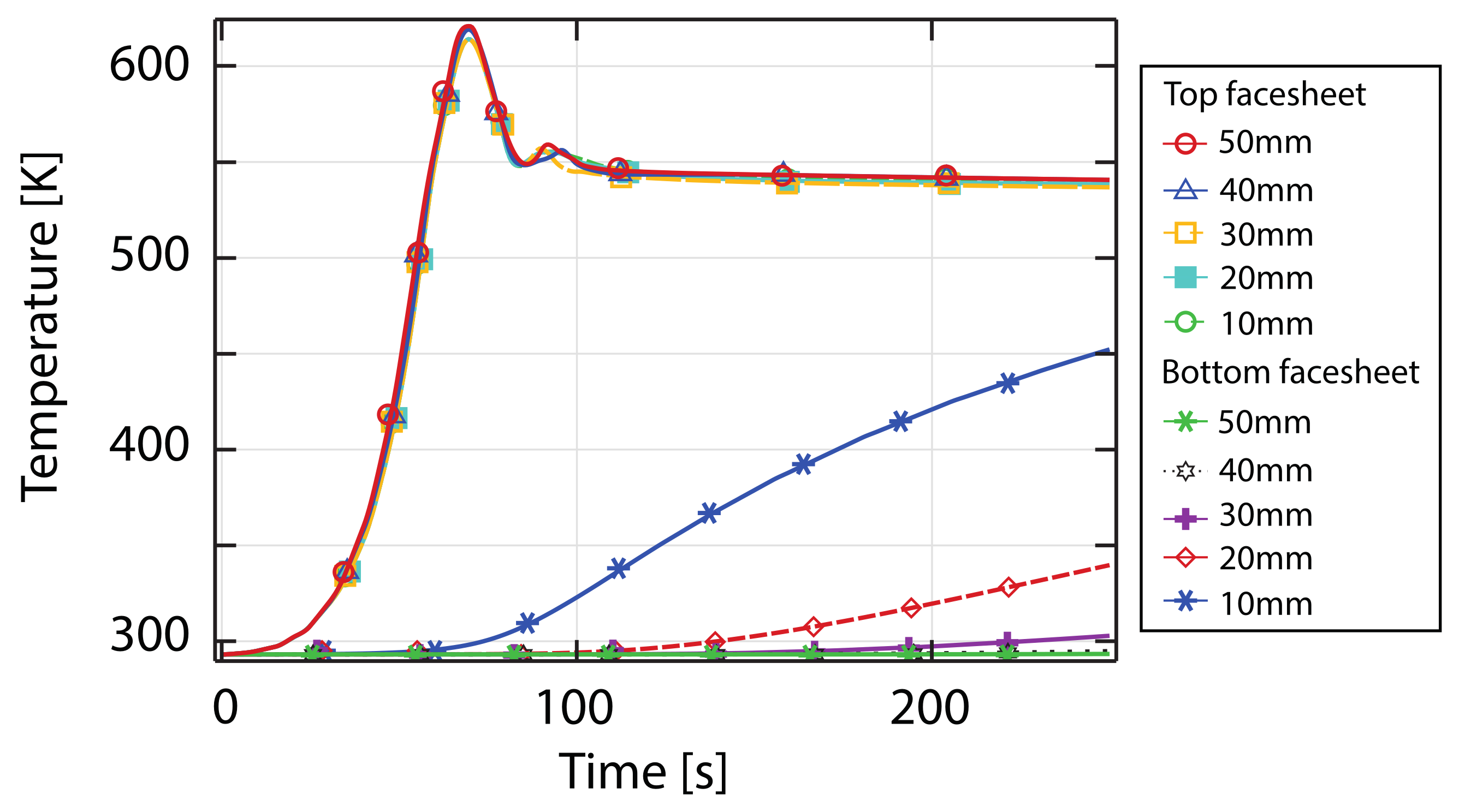
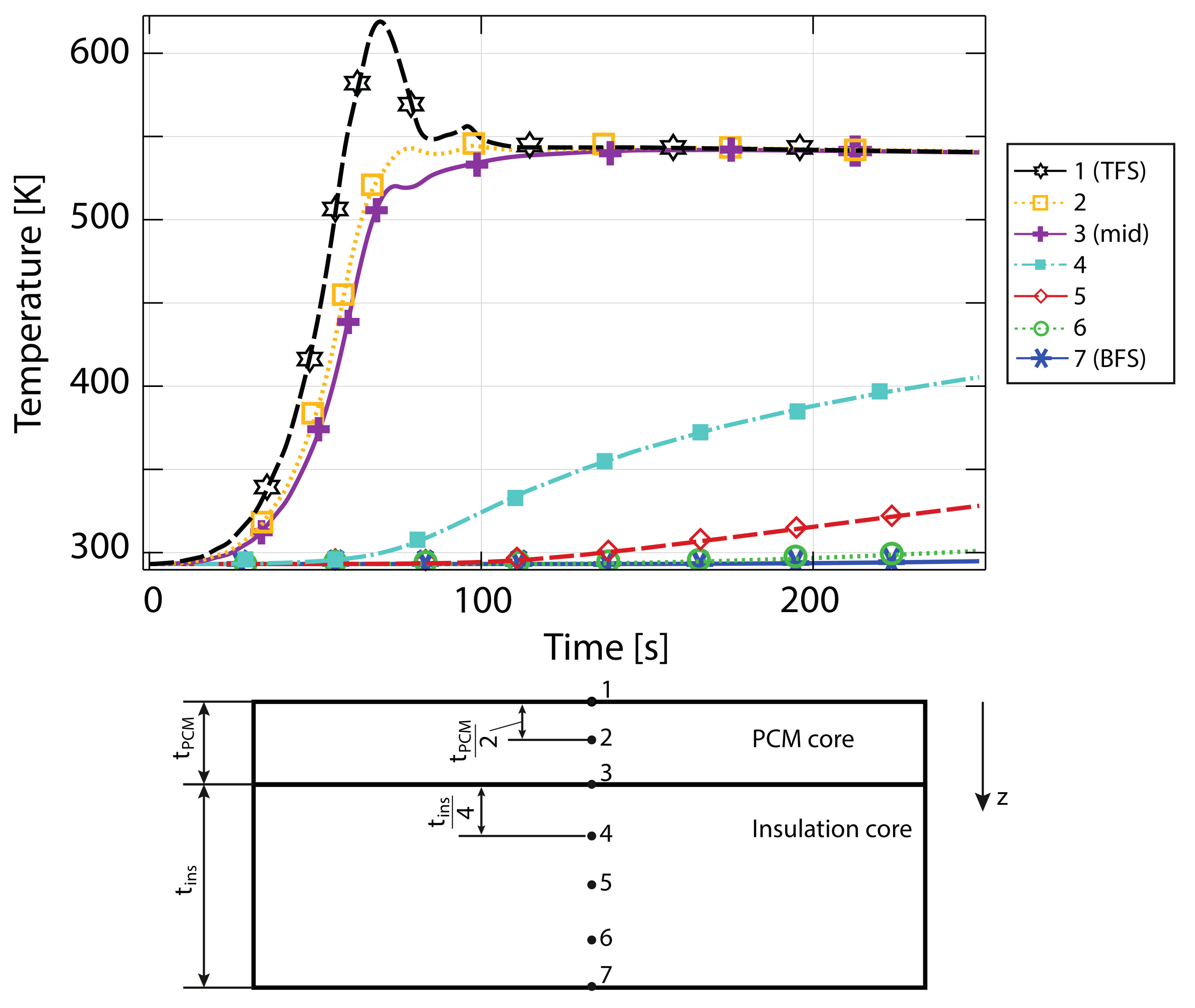
5.4. Thermal Response of the Lattice Core-PCM ITPS

In Figure 12, the wall temperature variations during the re-entry trajectory for different PCMs are shown. The geometric parameters are fixed to allow comparability between the results ( t c P C M = 10 mm , ϵ = 0.9 , t c i n s = 40 mm ). The other parameters are fixed a priori, as reported in Table 1.
It can be noticed that a low temperature peak at the top face sheet corresponds to the eutectic mixture Li2CO3(22%)-Na2CO3(16%)-K2CO3, which, however, exhibits a much higher melting point. This indicates that the thermal behaviour is ascribed to only sensible heat storage. This indicates that the material is not suitable for lightweight latent heat thermal energy storage, as its thermal behaviour is only related to the high thermal mass.
Erythritol, which is the lightest material and also exhibits the lowest melting point, is not suitable for the application. Although a low melting point is advantageous, the low latent heat of fusion compared to other materials makes it an inappropriate choice. The KCl-MgCl2 mixture exhibits a comparably high latent heat, which is shown via the flattening of the temperature curve around its melting point. However, the melting point is higher than that of the LiCl-LiOH mixture, which also shows the highest latent heat of fusion. Thus, the material choice for further consideration in the geometric parametric study falls on the LiCl-LiOH mixture.
In the following Figure 13, Figure 14 and Figure 15, the parametric study for different geometrical parameters is described. Figure 13 shows the wall temperature (top face sheet) evolution for different PCM core thicknesses and porosities of the lattice structure. It can be noticed that the thickness has the highest influence on the thermal behaviour. Diminishing returns in terms of wall temperature reduction are observed with increasing thickness. On the other hand, for a small core thickness, the effect of varying porosity, and thus varying effective thermal conductivity, is marginal. However, for increasing core thicknesses, the effective thermal conductivity becomes more relevant. Indeed, the difference between wall temperature peaks at different porosities increases for the same core thickness.
One can notice that the peak of the temperature curve corresponding to a wall thickness of 20 mm and porosity ϵ = 0.95 is higher than the one corresponding to a core thickness 10 mm and porosity ϵ = 0.9 . Even in this case, diminishing returns are observed. Higher peak temperature reductions are observed, e.g., between ϵ = 0.95 and ϵ = 0.9 than between ϵ = 0.85 and ϵ = 0.8 .
If one considers mass as a limiting constraint, no trivial optimum exists. To minimise mass, porosity should be as high as possible, as the lattice core material is heavier than the PCM material. The core thickness has a cubic relationship with the bending stiffness of the structure. Therefore. it can not be a priori minimised.
One should notice that all configurations considered are effective in reducing the wall temperature with respect to the case of sensible thermal energy storage of, e.g., a corrugated core ITPS. Indeed even for a core thickness of only 5 mm, the wall temperature reaches a peak of maximum 797 K (524 ℃), which is well below the maximum operative temperature of both Inconel 718 and CuCr1Zr alloys. Therefore, a valid range of core thickness between 5 mm and 10 mm can be considered for application. All in all, a sweet spot can be identified at a core thickness of 10 mm and a porosity of ϵ = 0.9 . In such a configuration, the wall temperature does not drastically overshoot the melting point of the PCM.
Figure 14 shows the temperature curves for the top face sheet and the bottom face sheet for different insulation core thicknesses. The PCM core geometrical features are fixed at the identified optimum. The porosity of the insulation core is fixed at ϵ = 0.95 to obtain a low effective thermal conductivity. Increasing the thickness leads to higher thermal resistance, which can be observed with the progressively flattening temperature curves of the bottom face sheet. The temperature of the top face sheet is marginally influenced by the insulation core, as the temperature curves for such a point of the component are dominated by the latent heat thermal energy storage. Considering the bottom face sheet temperature constraints previously described, the case of an insulation core thickness of 10 mm should be discarded. On the other hand, an insulation core thickness of 50 mm does not bring appreciable differences with respect to the thinner 40 mm case. Therefore, it should also be discarded. Table 4 summarizes the final material choice and the identified valid geometrical parameters range. Finally, Figure 15 shows the temperature curves of different positions along the out-of-plane direction for the case of a hierarchical sandwich with a PCM core thickness of 10 mm, ϵ = 0.9 , and a thickness of the insulation layer of 40 mm.
One can observe that the overall areal weight of the obtained composite is higher than both solutions previously considered. This is mainly due to the high density of the structural materials in face sheets and lattice cores. However, a proper treatment of the overall mass cannot ignore the contribution of the structural design to the mass budget. This is described in what follows.

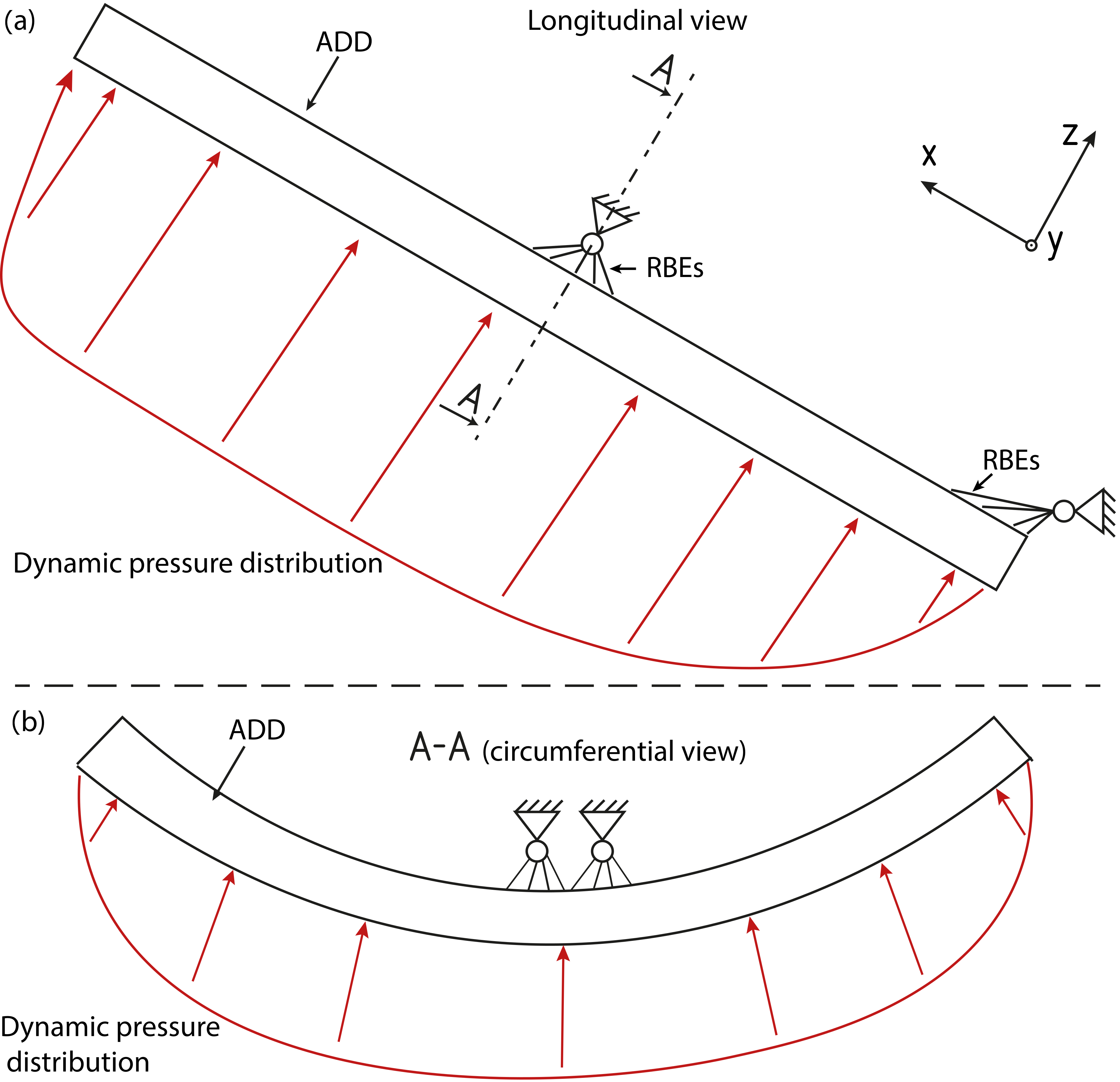
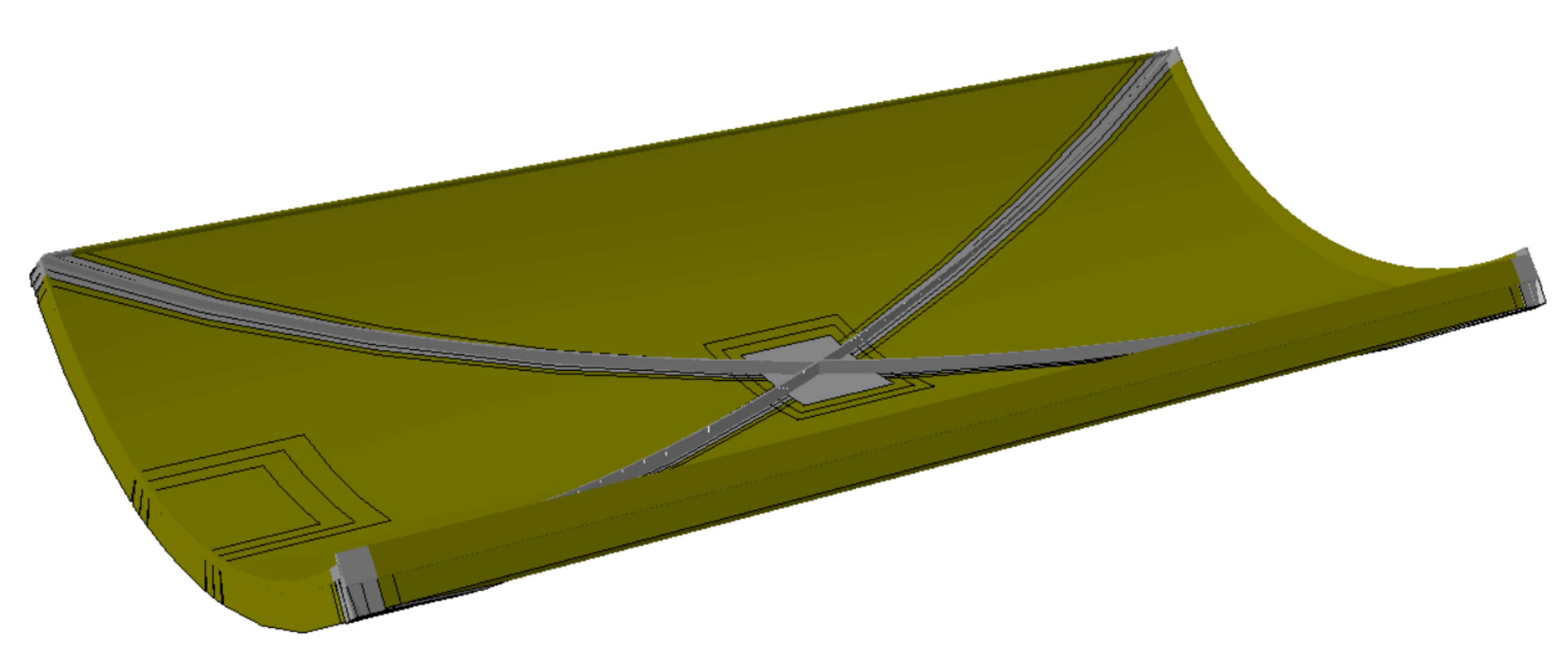
5.5. Preliminary Structural Design

It was shown that an ablative material can offer the best thermal protection capability at the minimum mass from a thermal design point of view. This conclusion is not trivial when considering the structural performance. In particular, regarding a heavily loaded structural element, such as the ADD discussed in this work, the structural mass can represent the highest contribution to the overall mass budget. Considering a sandwich ITPS could therefore be advantageous for overall mass reduction. Having both the thermal and the structural mass integrated within one component, no add-on mass such as in the case of the ablative TPS is present. Additionally, from the operative point of view of an RLV, a reusable passive TPS is considered advantageous compared to ablative materials. However, ITPSs not only face mechanical loads due to the dynamic pressure, but additional thermo-mechanical ones. Therefore, a mechanical analysis of the considered solutions is necessary to assess the overall lightweight potential of the considered solutions. The thermal loads applied are the ones corresponding to the time step at which the highest thermal gradient is present. The mechanical load is the same for all three structures, namely the maximum dynamic pressure distribution (see Figure 7).
In the following, the two thermally optimised ITPS concepts from above are analysed using FEM simulations under mechanical and thermal loads. For the ablative TPS concept, a CFRP sandwich structure is designed iteratively to function as a load-bearing structure attached to the inside of the ablative layer of the ADD. This allows for a comparison of structural performance as well as total mass of the concepts. The following configurations were chosen from the previous sections:
  • For the corrugated core ITPS solution, no modification of the design is made, and the final geometrical configuration obtained from the thermal optimization (see Section 5.3) is analysed under mechanical and thermal loads.
  • The considered configuration of the lattice core-PCM ITPS is the one on the higher end of the geometrical ranges considered in Section 5.4 (i.e., t c P C M = 10 mm , ϵ = 0.9 , t c i n s = 40 mm ).
  • The mechanical analysis of the load-bearing structure for the ablative PICA TPS analysed in Section 5.2 is used to iteratively optimise the CFRP laminate. The goal of the optimization is to obtain a layup that does not exhibit material failure under the mechanical loads.
The three configurations are tested under the same mechanical boundary conditions described in Section 5.1 (see Figure 7).

5.5.1. Load-Bearing Structure Carrying the Ablative TPS

The dynamic pressure load acts on the component mainly via bending. Thus, the most promising lightweight design concept is that of a sandwich structure. To maximize the load bearing capability to mass ratio, the sandwich is designed with an aluminium honeycomb core between CFRP face sheets. As schematised in Figure 7, the bending load due to pressure acts bi-directionally on the component, i.e., bending it around the longitudinal (x-)axis and the circumferential (y-)axis. While an increase of the aluminium core thickness increases the stiffness of the structure, stresses in the face sheets are increased as well. Therefore, X-shaped aluminium reinforcements are introduced on the inner face sheet of the ADD against bending deformations, as shown in Figure 16.
The layup and dimensions of the structure were determined in an iterative design process using geometrically non-linear static analyses in Abaqus® 2020 on a mesh consisting of a linear shell and beam elements. Typical material data for unidirectional (UD) T700 prepreg material and aluminium honeycomb are used (see Appendix B). Due to the optimised ablative TPS, virtually no thermal loads act on the load-bearing structure underneath. Therefore, only dynamic pressure loads (see Figure 8b) are considered. In the laminate, the number and orientation of the UD layers was iterated, as well as the cross-section of the X-shaped reinforcements and the frame along the ADD’s perimeter.
The obtained design has face sheet laminates with a thickness of 1.75 mm each and a core thickness of 50 mm, resulting in a mass of the structure of 35 kg. For the evaluation of stresses in the composite material, the Tsai–Wu failure criterion [41] is utilised with the goal of maintaining the criterion in all layers below 1.0. For sake of brevity, only the failure criterion values in the most critical composite layer with the highest failure criterion overall are reported (see Figure 17). As the maximum value of 0.92 occurs at border of the ideally stiff boundary condition, stresses in the real component are assumed to be lower than calculated here.
This preliminary structural design study was performed to obtain a benchmark design whose mass can then be compared to the lattice core and corrugated core ITPS solutions. It can be concluded that it was feasible to find a lightweight design for the load-bearing structure when subjected to dynamic pressure loads. The reported mass of 35 kg is that of the load-bearing structure only. The mass of the PICA TPS layer amounts to 32 kg per ADD, thus resulting in an overall mass of 67 kg (neglecting bonding, attachment points, inserts, etc.).

5.5.2. Corrugated Core ITPS

For the corrugated core ITPS, the optimised configuration obtained from the thermal study is considered in the mechanical analysis. A quasi-isotropic laminate layup is considered. The same mechanical boundary conditions described for the honeycomb structure of the ablative TPS are applied (see Figure 7), and the commercial solver ANSYS® APDL is used. To take into account the thermal deformation, a coupled thermo-mechanical analysis is performed. The thermal solver is used to obtain the temperature field on the whole structure for the time point at which the maximum outer facesheet temperature is reached, which also corresponds to the maximum thermal gradient. The analysis leads to the results shown in Figure 18. The material properties are reported in Table A5. Due to the lack of established failure criteria for CMCs, the Von Mises equivalent stress on the component is reported. Widespread failure in several parts of the component is detected. The material tensile strength of 260 MPa is exceeded in several points of the structure, even far from the constraints where a local, artificial increase in stress is observed. This is mainly due to the high thermal gradient acting on the structure. The sandwich structure offers a high bending stiffness, which, although advantageous for the mechanical loading of the component, leads to high thermally induced stresses. Although the material exhibits a low coefficient of thermal expansion (CTE), the thermal stresses still exceed the allowable values in several sections of the component. Future design involving different fibre orientations that achieve a three-dimensional tailoring of the CTE might mitigate the incurred failures while retaining high bending stiffness.

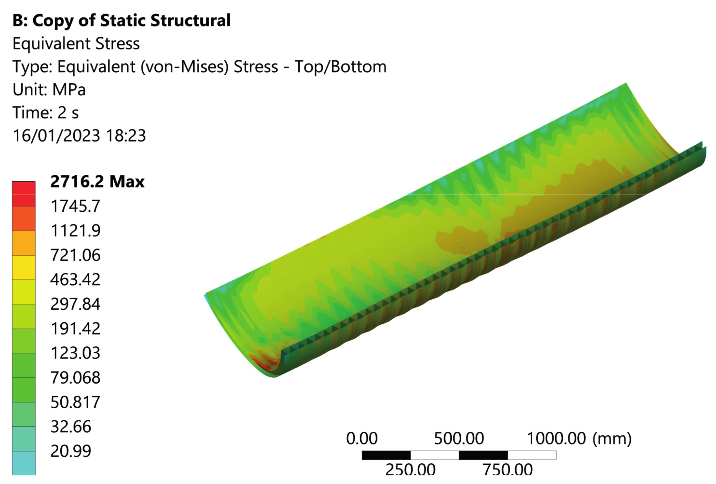
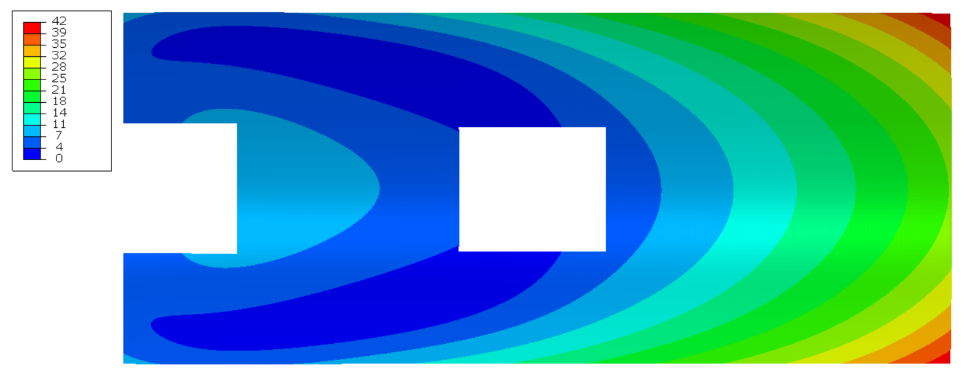
5.5.3. Lattice Core-PCM ITPS

The lattice core/PCM solution faces milder thermo-mechanical loads compared to the corrugated core ITPS (cf. Section 5). The maximum top face sheet temperature reaches 618 K, whereas the inner face sheet remains at the initial temperature of 300 K (see Figure 15). Due to the direct bonding of different materials, their difference in coefficient of thermal expansion (CTE) leads to high thermo-mechanical stresses. To calculate these stresses, the temperature field through the thickness of the ADD is required. Therefore, in a first step, we calculate the temperature field by a steady-state heat transfer simulation in Abaqus® 2020.
The thermo-mechanical model consists of linear shell elements to model the three face sheets and linear beam elements for the lattice struts. The structural analysis is split in two load steps:
First, the previously calculated temperature field is applied to the model with respect to its stress-free initial state at a temperature of 298 K (room temperature). The CTEs of the materials are assumed constant over the entire temperature range. For the FE model of the lattice-PCM ITPS solution, the same constraints are used as in the simulations of the other two TPS concepts (see Figure 7).
In a second load step, the dynamic pressure during re-entry is applied to the outer face sheet of the sandwich structure in addition to the persisting thermo-mechanical loads. The resulting deformation is plotted in Figure 19, showing a maximum displacement of 42 mm.
The results of the structural analysis for both load cases are summarised in Table 5. It can be observed that the greater part of the deformations and stresses arises from the thermal gradients, not from the additional pressure load. The comparison with the allowable yield stresses leads to the conclusion that the thermally optimised design is not feasible from a mechanical design point of view.
In all layers made from Inconel 718 (i.e., face sheets and inner lattice core), stresses do not exceed the allowable to a level that could not be managed by further optimization of geometric parameters.
The lattice in the outer core is made from an additively manufactured CuCr1Zr alloy with a yield stress of 310 MPa. The yield stress in the CuCr1Zr struts is exceeded by a factor of more than two in both load cases. It can therefore be concluded that the design resulting from the thermal optimization is not feasible from a mechanical engineering point of view. This requires the choice of a different material for the outer lattice core that has high strength and at the same time good thermal conductivity, e.g., tungsten.

5.6. Final Mass Estimation

The three presented ADD concepts were initially optimised for thermal performance (Section 5.2, Section 5.3 and Section 5.4) and then analysed in terms of mechanical performance (cf. Section 5.5.2 and Section 5.5.3). The load-bearing structure for the ablative TPS was iterated to obtain a feasible design of the composite sandwich layup (Section 5.5.1). For a holistic comparison of the concepts in the context of their application in a reusable microlauncher, their masses are an important performance indicator and are therefore compiled in Table 6.
It can be seen that the ablative TPS with the load-bearing CFRP sandwich structure is the lightest concept, followed by the CMC corrugated core. The proposed hierarchical lattice core / PCM solution has a significantly higher mass, at a factor of three compared to the other concepts. It must be noted that the CMC corrugated core as well as lattice core/PCM solution were not optimised for structural performance but only for thermal performance. Therefore, their masses as well as the resulting stresses cannot be taken as an absolute measure for performance of the concepts. Rather, the comparably high mass/poor mechanical performance of the ITPS solutions should be seen as an indication that further optimization of these structures is required.

6. Conclusions

This work described the multidisciplinary design of an aerodynamic drag device used to allow a passive re-entry, i.e., avoiding retropropulsion, of a reusable launch vehicles’ first stage. The drag device consists of four sub-components and represents, in a closed configuration, the interstage of the launcher. In the extended configuration, high thermal and mechanical loads are experienced. To achieve a lightweight design, a holistic design approach is required. Therefore, in this work, both thermal and mechanical analyses are conducted. Three different concepts are compared: One is based on an ablative thermal protection system and a CFRP-aluminium honeycomb sandwich structure. The second is a sandwich structure representing a so-called integrated thermal protection system based on a ceramic matrix composite. The third is, as well, an integrated thermal protection system, whose design is based on the use of metallic lattice structures in which a phase change material is embedded. The main results as well as the outlook for each analysed technology are summarised as follows:
  • Ablative TPS solution
    -
    The separation of thermal and structural functions allows one to use efficient materials and construction methods for each absolved function, namely PICA for thermal protection and CFRP-aluminium honeycomb sandwich for load-bearing functionality.
    -
    The solution delivers the lowest overall mass.
    -
    It is easier to obtain a feasible solution because of the two high-TRL solutions used in this concept.
    -
    Reusability is a concern. Indeed, after-flight maintenance operations should include either a check of the receded amount of ablative material or a re-application. Alternatively, a fast-swap concept can be considered, directly removing and substituting both the structural element and the thermal protection system.
  • ITPS-CMC corrugated core sandwich
    -
    The concept represents a lightweight, reusable solution for thermal protection purposes.
    -
    However, the thermally optimised solution does not withstand the thermo-mechanical loads.
    -
    Although ceramic matrix composites exhibit a low coefficient of thermal expansion, the high thermal gradients and the high stiffness lead to high thermal stresses compared to the low tensile strength of the material. Improvements in this direction are needed to allow a load bearing functionality of CMC-based TPS. Three-dimensional CTE tailoring via appropriate fibre orientation can be considered in future work.
  • ITPS-Lattice core/PCM
    -
    The integration of a PCM drastically reduces outer wall (top face sheet) temperatures and therefore allows use of materials with high specific mechanical properties, i.e., Inconel.
    -
    However, thermal stresses above the yield strength of the respective materials in the different layers are identified. These can be caused by mismatch in the CTE of the different materials and high bending stiffness. Additionally, the use of copper alloy, although beneficial to improving the thermal conductivity of the PCM, has the drawback of a low specific yield strength.
    -
    Different material combinations can be considered in the future. In particular, given the obtained operative temperatures, titanium based alloys are good candidates for the face sheets and for the insulation core. High temperature aluminium alloys, which retain their strength up to 300℃, could be considered for the PCM core. This way, a higher lightweight potential can be obtained.
    -
    Additive manufacturing allows for local adaptation of the structure. Local optimization of lattice unit cell parameters can allow further mass reduction with improved thermo-mechanical behaviour.
For use in a reusable microlauncher, a holistic assessment of load-bearing TPS structures is required. Specifically, the reusability requirement could make the use of ablative TPS expensive compared to heavier solutions with lower expected overhaul time and cost between launches.
Future work should aim at improved thermal analyses with better estimation of the boundary conditions, i.e., a better definition of the ambient temperature for the radiative heat exchange term of the outer surface. Such ambient temperature should be based on piecewise interpolation of ambient temperatures at different points during the flight trajectory.
Furthermore, future activities will concentrate on the multi-objective (thermal and mechanical) optimisation of the two reusable TPS solutions (CMC corrugated and lattice PCM). Only in this way can an integrated structure with good thermal and mechanical performance be obtained. More adequate material choice and combination should be considered among the parameters of the optimisation as well. Furthermore, manufacturing constraints that hinder the construction methodology need to be taken into account. Indeed, the manufacturing of CMCs is still not mature enough to monolithically realise such wide and complex components. On the other hand, the maximum size of realisable metallic structures via additive manufacturing is still small compared to the size of the component considered in this work. The joining techniques, e.g., brazing or laser welding, of different parts of the hierarchical sandwich structure may represent a bottleneck and should be thoroughly investigated. Furthermore, compatibility of the chosen PCM with the core and face sheet material combination should be evaluated case by case. The volume expansion of the PCM after melting should also be taken into account. Although technical solutions like the use of membranes or expansion chambers exist, these might affect the overall structural design. Finally, different kinds of unit cells and local tailoring of the cell parameters of lattice structures can be used to obtain a tailored coefficient of thermal expansion. This would allow one to reduce overall thermal stresses. For the high flexibility in the design process, additively manufactured lattice structures can be considered viable candidates to obtain holistically optimised structures with thermal protection functionality.

Author Contributions

Conceptualization, S.P.; Methodology, S.P.; Software, N.H. and S.P.; CFD analyses, A.Z.; Thermal analyses, S.P.; Mechanical analyses, D.P. and S.P.; Writing—original draft preparation, S.P. and D.P.; Project administration, K.-U.S., R.B., and A.D.; Funding acquisition, A.D. and R.B. All authors have read and agreed to the published version of the manuscript.

Funding

This research was funded by EU Horizon 2020 Programme, grant number 870340.

Data Availability Statement

The open source software Hot-STARSHIP is available at the following link: https://github.com/nilsh7/Hot-STARSHIP/tree/v1.0.0 (accessed on 18 of March 2023) or after contacting the corresponding author.

Acknowledgments

The authors would like to thank Giovanni Medici from DEIMOS SPACE S.L.U for the information supplied about mission analysis and trajectory. The authors would also like to thank Tobias Schalm and Maximilian Schirp-Schoenen for their redactional help in reviewing the paper.

Conflicts of Interest

The authors declare no conflict of interest.

Abbreviations

The following abbreviations are used in this manuscript:
ADDAerodynamic drag device
BFSBottom face sheet
CFDComputational fluid dynamic
CFRPCarbon fibre-reinforced polymer
CMCCeramic matrix composite
CTECoefficient of thermal expansion
DOFDegree of freedom
FEMFinite element method
FVMFinite volume method
ITPSIntegrated thermal protection system
PCMPhase change material
PICAPhenolic impregnated carbon ablator
RLVReusable launch vehicle
SLSQPSequential least squares programming
TACOTTheoretical ablative composite for open testing
TFSTop face sheet
TPSThermal protection system
TRLTechnology readiness level
UDUnidirectional

Appendix A. Verification of the Hot-STARSHIP Solver

In the test, a 5 cm thick piece of TACOT material is heated for one minute and cooled off for another minute afterwards. The parameters for this problem are depicted in Table A1.
Table A1. Parameters for ablative test.
PropertySymbolValue
Initial length l 0 50 mm
Initial temperature T i n i 300 K
Pressurep101,325 Pa
Turbulent factor λ 0.5
The aerodynamic boundary condition is used with time-varying values of the transfer coefficient ρ e u e C H 0 and recovery enthalpy h r to achieve the heating and cooling phase. Note that, in contrast to the use of pre-generated B -tables in [33], the results presented here are computed with our own B -tables that are extracted from Mutation++ as part of the process. The time step is chosen to be 0.1   s , and the grid has a first cell thickness of 0.05   m m and a maximum growth factor of 1.03. The temperature and recession history for a calculation with Amaryllis and PATO are obtained from [33]. Figure A1 shows a comparison of surface recession s and char and gas mass flow rate ( m ˙ c and m ˙ g ) as a function of time.
Figure A1. Comparison of Hot-STARSHIP and Amaryllis/PATO recession and mass flow rates.
Aerospace 10 00319 g0a1
Hot-STARSHIP analysis results in a 7.6% higher final recession value s ( 15.6   m m versus 14.5   m m ). This difference can be attributed to the initial difference in char mass flow rate m ˙ c where Hot-STARSHIP peaks, whereas PATO/Amaryllis show a smoother transient behaviour. As time progresses, the two curves approach each other. In the end, the difference in recession rate s ˙ is about 4.6%. Once the heat flux input ends, both programs conform to each other. The difference in recession amount can also be observed in the temperature plots in Figure A2. The temperatures are plotted in stationary locations. Thus, once the surface has receded to a fixed location, the location’s temperature history ends and merges with the surface temperature history at that point. Both programs are in good agreement of the surface temperature. Wider differences are only observable in the first 20 s where the higher char ablation rate of Hot-STARSHIP provides more cooling. In the fixed locations, the temperature difference between both programs grows with time. As noted, part of this is because of the higher recession amount of Hot-STARSHIP. Because with higher recession amounts fixed locations are closer to the surface and the temperature gradients are large due to low conductivity, differences are observed (see also Figure A3).
Note that one of the main constraints of thermal protection system thickness, the back-face temperature at 50 m m , is in good agreement for both programs. The final difference is about 12 K , and the average difference is even lower as the two curves cross each other.
Figure A2. Comparison of Hot-STARSHIP and Amaryllis/PATO temperature curves.
Aerospace 10 00319 g0a2
Finally, Figure A3 shows internal temperature profiles shortly after the heating begins (2 s ), when the heating stops (60 s ), shortly after the heating stops ( 60.1   s ) at the very end of the calculation (120 s ), and some intermediate values.
Figure A3. Temperature profiles of Hot-STARSHIP calculation at selected times.
Aerospace 10 00319 g0a3
During heating, large temperature gradients are present in the first few millimeters to centimeters, reaching values of up to 700 K / m m . This explains the seemingly large differences in Figure A2 arising from different proximity to the surface. Once the heating ends, the surface temperature drops rapidly, leading to peak temperature not at the surface, but 5 m m into the material. From this point onward, the temperature profile flattens out as dictated by the second order conductivity equation.
The differences between Hot-STARSHIP and PATO or Amaryllis might be attributed to the use of pre-generated B -tables for PATO and Amaryllis, whereas this is not the case for Hot-STARSHIP, where the tables are computed via Mutation++. In addition, PATO and Amaryllis are “type 2” [42] solvers, whereas Hot-STARSHIP can be classified as a “type 1” solver. This means that in addition to the details resolved in Hot-STARSHIP, PATO and Amaryllis consider Darcy’s law for convective transport of pyrolysis gas as well as porosity and permeability for diffusive transport [42]. Whereas Hot-STARSHIP assumes that the gas leaves instantly, solving Darcy’s law as done in PATO could hold back some gas that then flows out more slowly, leading to a higher gas mass flow rate. This behaviour would also increase the cooling of the in-depth material, which explains the lower predicted temperatures of PATO and Amaryllis. On the other hand, the slightly lower surface temperature of Hot-STARSHIP can be explained by the higher char mass flow rate that provides more surface cooling.

Appendix B. Material Data

The following material data were acquired from the Ansys® database for a T700 CFRP composite material and for an aluminium honeycomb.
Table A2. UD composite stiffness properties [MPa].
E1E2Nu12G12G13G23 α 11 α 22 α 33
121,00086000.27470031004700 4.7 × 10 7 3 × 10 5 3 × 10 5
Table A3. UD composite failure stresses [MPa].
Tensile XCompression XTensile XYCompression XYShear Strength XY
2321−108229−10060
Table A4. Al honeycomb stiffness properties [MPa].
E1E2E3Nu12Nu13Nu23G12G13G23
112550.490.010.01 1 × 10 6 3770
The material data for the CMC are reported with reference to [10]:
Table A5. CMC material properties.
Density [g/cm3]Tensile Str. [MPa]Compressive Str. [MPa]Young Modulus [GPa]
1.826059090

References

  1. Niederstrasser, C.G. The small launch vehicle survey a 2021 update (The rockets are flying). J. Space Saf. Eng. 2022, 9, 341–354. [Google Scholar] [CrossRef]
  2. Governale, G.; Rimani, J.; Viola, N.; Villace, V.F. A trade-off methodology for micro-launchers. Aerosp. Syst. 2021, 4, 209–226. [Google Scholar] [CrossRef]
  3. Medici, G.; Bergström, R.; Martí, L.; Palumbo, N.; Hove, B.; Viladegut, A.; Paris, S.; Soepper, M.; Bhardwaj, P.; Rellakis, D.; et al. A Novel Design Approach for a Reusable VTOL Micro Launch Vehicle. In Proceedings of the 72nd International Astronautical Congress, Dubai, United Arab Emirates, 25–29 October 2021; Available online: https://www.researchgate.net/publication/360008193_A_novel_design_approach_for_a_reusable_VTOL_Micro_Launch_Vehicle (accessed on 21 March 2023).
  4. Marwege, A.; Gülhan, A.; Klevanski, J.; Hantz, C.; Karl, S.; Laureti, M.; De Zaiacomo, G.; Vos, J.; Jevons, M.; Thies, C.; et al. RETALT: Review of technologies and overview of design changes. CEAS Space J. 2022, 14, 433–445. [Google Scholar] [CrossRef] [PubMed]
  5. Natali, M.; Kenny, J.M.; Torre, L. Science and technology of polymeric ablative materials for thermal protection systems and propulsion devices: A review. Prog. Mater. Sci. 2016, 84, 192–275. [Google Scholar] [CrossRef]
  6. Uyanna, O.; Najafi, H. Thermal protection systems for space vehicles: A review on technology development, current challenges and future prospects. Acta Astronaut. 2020, 176, 341–356. [Google Scholar] [CrossRef]
  7. Dorsey, J.T.; Poteet, C.C.; Wurster, K.E.; Chen, R.R. Metallic Thermal Protection System Requirements, Environments, and Integrated Concepts. J. Spacecr. Rockets 2004, 41, 162–172. [Google Scholar] [CrossRef]
  8. Le, V.T.; Goo, N.S. Design, Fabrication, and Testing of Metallic Thermal Protection Systems for Spaceplane Vehicles. J. Spacecr. Rockets 2021, 58, 1043–1060. [Google Scholar] [CrossRef]
  9. Le, V.T.; Goo, N.S. Thermomechanical Performance of Bio-Inspired Corrugated-Core Sandwich Structure for a Thermal Protection System Panel. Appl. Sci. 2019, 9, 5541. [Google Scholar] [CrossRef] [Green Version]
  10. Heidenreich, B. C/SiC and C/C-SiC Composites. In Ceramic Matrix Composites; Bansal, N.P., Lamon, J., Eds.; John Wiley & Sons, Inc.: Hoboken, NJ, USA; pp. 147–216. [CrossRef]
  11. Glass, D.E. Ceramic matrix composite (CMC) thermal protection systems (TPS) and hot structures for hypersonic vehicles. In Proceedings of the 15th AIAA International Space Planes and Hypersonic Systems and Technologies Conference, Dayton, OH, USA, 28 April–1 May 2008; pp. 1–36. [Google Scholar] [CrossRef] [Green Version]
  12. Ferraiuolo, M.; Scigliano, R.; Riccio, A.; Bottone, E.; Rennella, M. Thermo-structural design of a Ceramic Matrix Composite wing leading edge for a re-entry vehicle. Compos. Struct. 2019, 207, 264–272. [Google Scholar] [CrossRef]
  13. Blosser, M.L.; Chen, R.R.; Schmidt, I.H.; Dorsey, J.T.; Poteet, C.C.; Bird, R.K.; Wurster, K.E. Development of advanced metallic thermal-protection-system prototype hardware. J. Spacecr. Rockets 2004, 41, 183–194. [Google Scholar] [CrossRef]
  14. Fischer, W.; Bolz, J. ULTIMATE: Metallic TPS for Future RLV’s. In Proceedings of the 9th AIAA/ASME Joint Thermophysics and Heat Transfer Conference, San Francisco, CA, USA, 5–8 June 2006. [Google Scholar] [CrossRef]
  15. Bapanapalli, S.; Martinez, O.; Gogu, C.; Sankar, B.; Haftka, R.; Blosser, M. (Student Paper) Analysis and Design of Corrugated-Core Sandwich Panels for Thermal Protection Systems of Space Vehicles. In Proceedings of the 47th AIAA/ASME/ASCE/AHS/ASC Structures, Structural Dynamics, and Materials Conference; 14th AIAA/ASME/AHS Adaptive Structures Conference, Newport, RI, USA, 1–4 May 2006. [Google Scholar] [CrossRef] [Green Version]
  16. Gogu, C.; Bapanapalli, S.K.; Haftka, R.T.; Sankar, B.V. Comparison of materials for an integrated thermal protection system for spacecraft reentry. J. Spacecr. Rockets 2009, 46, 501–513. [Google Scholar] [CrossRef]
  17. Li, Y.; Zhang, L.; He, R.; Ma, Y.; Zhang, K.; Bai, X.; Xu, B.; Chen, Y. Integrated thermal protection system based on C/SiC composite corrugated core sandwich plane structure. Aerosp. Sci. Technol. 2019, 91, 607–616. [Google Scholar] [CrossRef]
  18. Le, V.T.; Ha, N.S.; Goo, N.S. Advanced sandwich structures for thermal protection systems in hypersonic vehicles: A review. Compos. Part B Eng. 2021, 226, 109301. [Google Scholar] [CrossRef]
  19. Yendler, B.; Dang, K.; Forrest, M. A Reusable Heat Shield Using Phase Change Materials. In Proceedings of the 44th AIAA Aerospace Sciences Meeting and Exhibit, Reno, NV, USA, 9–12 January 2006. [Google Scholar] [CrossRef]
  20. Cao, C.; Wang, R.; Xing, X.; Liu, W.; Song, H.; Huang, C. Performance improvement of integrated thermal protection system using shaped-stabilized composite phase change material. Appl. Therm. Eng. 2020, 164, 114529. [Google Scholar] [CrossRef]
  21. Nazir, H.; Batool, M.; Osorio, F.J.B.; Isaza-Ruiz, M.; Xu, X.; Vignarooban, K.; Phelan, P.; Inamuddin; Kannan, A.M. Recent developments in phase change materials for energy storage applications: A review. Int. J. Heat Mass Transf. 2019, 129, 491–523. [Google Scholar] [CrossRef]
  22. Hubert, R.; Bou Matar, O.; Foncin, J.; Coquet, P.; Tan, D.; Li, H.; Teo, E.H.T.; Merlet, T.; Pernod, P. An effective thermal conductivity model for architected phase change material enhancer: Theoretical and experimental investigations. Int. J. Heat Mass Transf. 2021, 176, 121364. [Google Scholar] [CrossRef]
  23. Piacquadio, S.; Schirp-Schoenen, M.; Mameli, M.; Filippeschi, S.; Schröder, K.U. Experimental Analysis of the Thermal Energy Storage Potential of a Phase Change Material embedded in Additively Manufactured Lattice Structures. Appl. Therm. Eng. 2022, 153, 119091. [Google Scholar] [CrossRef]
  24. Bühring, J.; Nuño, M.; Schröder, K.U. Additive manufactured sandwich structures: Mechanical characterization and usage potential in small aircraft. Aerosp. Sci. Technol. 2021, 111, 106548. [Google Scholar] [CrossRef]
  25. Chen, Y.K.; Milos, F.S. Multidimensional finite volume fully implicit ablation and thermal response code. J. Spacecr. Rockets 2018, 55, 914–927. [Google Scholar] [CrossRef]
  26. Chen, Y.K.; Milos, F.S. Two-Dimensional Implicit Thermal Response and Ablation Program for Charring Materials. J. Spacecr. Rockets 2001, 38, 473–481. [Google Scholar] [CrossRef]
  27. Scoggins, J.B.; Leroy, V.; Bellas-Chatzigeorgis, G.; Dias, B.; Magin, T.E. Mutation++: MUlticomponent Thermodynamic And Transport properties for IONized gases in C++. SoftwareX 2020, 12, 100575. [Google Scholar] [CrossRef]
  28. Gordon, S.; McBride, B.J. Computer Program for Calculation of Complex Chemical Equilibrium Compositions and Applications. Part 1: Analysis. NASA Technical Report, Document ID 19950013764; NASA Lewis Research Center: Cleveland, OH, USA, 1994. [Google Scholar]
  29. De Mûelenaere, J.; Lachaud, J.; Mansour, N.N.; Magin, T.E. Stagnation line approximation for ablation thermochemistry. In Proceedings of the 42nd AIAA Thermophysics Conference, Honolulu, HI, USA, 27–30 June 2011; pp. 1–14. [Google Scholar] [CrossRef]
  30. Bonacina, C.; Comini, G.; Fasano, A.; Primicerio, M. Numerical solution of phase-change problems. Int. J. Heat Mass Transf. 1973, 16, 1825–1832. [Google Scholar] [CrossRef]
  31. Amar, A.J. Modeling of One-Dimensional Ablation with Porous Flow Using Finite Control Volume Procedure. Master’s Thesis, North Carolina State University, Raleigh, NC, USA, 2006. [Google Scholar]
  32. Chen, Y.K.; Milos, F.S. Ablation and thermal response program for spacecraft heatshield analysis. In Proceedings of the 36th AIAA Aerospace Sciences Meeting and Exhibit, Reno, NV, USA, 12–15 January 1998; Volume 36. [Google Scholar] [CrossRef]
  33. Lachaud, J.; Martin, A.; Eekelen, T.V.; Cozmuta, I. Ablation test-case series #2-Numerical simulation of ablative-material response: Code and model comparisons. In Proceedings of the 5th Ablation Workshop, Lexington, KY, USA, 28 February–1 March 2012. [Google Scholar]
  34. The SciPy Community. scipy.optimize.toms748. Available online: https://docs.scipy.org/doc/scipy/reference/generated/scipy.optimize.toms748.html (accessed on 21 March 2023).
  35. Alefeld, G.E.; Potra, F.A.; Shi, Y. Algorithm 748: Enclosing Zeros of Continuous Functions. ACM Trans. Math. Softw. TOMS 1995, 21, 327–344. [Google Scholar] [CrossRef]
  36. Virtanen, P.; Gommers, R.; Oliphant, T.E.; Haberland, M.; Reddy, T.; Cournapeau, D.; Burovski, E.; Peterson, P.; Weckesser, W.; Bright, J.; et al. SciPy 1.0–Fundamental Algorithms for Scientific Computing in Python. Nat. Methods 2019, 17, 261–272. [Google Scholar] [CrossRef] [Green Version]
  37. Varelas, K.; Dahito, M.A. Benchmarking multivariate solvers of scipy on the noiseless testbed. In Proceedings of the GECCO 2019 Companion–Proceedings of the 2019 Genetic and Evolutionary Computation Conference Companion, Prague, Czech Republic, 13–17 July 2019; pp. 1946–1954. [Google Scholar] [CrossRef] [Green Version]
  38. Sutton, K.; Graves, R.A.J. A General Stagnation-Point Convective-Heating Equation for Arbitrary Gas Mixtures; Technical Report November; NASA Langley Research Center: Hampton, VA, USA, 1971. [Google Scholar]
  39. Chen, Y.K.; Milos, F.S. Ablation and Thermal Response Program for Spacecraft Heatshield Analysis. J. Spacecr. Rockets 1999, 36, 475–483. [Google Scholar] [CrossRef] [Green Version]
  40. Tran, H.; Johnson, C.; Hsu, M.T.; Chem, H.; Dill, H.; Chen-Johnson, A.; Tran, H.; Johnson, C.; Hsu, M.T.; Chem, H.; et al. Qualification of the forebody heatshield of the Stardust’s Sample Return Capsule. In Proceedings of the 32nd Thermophysics Conference, Atlanta, GA, USA, 23–25 June 1997. [Google Scholar] [CrossRef]
  41. Tsai, S.W.; Wu, E.M. A general theory of strength for anisotropic materials. J. Compos. Mater. 1971, 5, 58–80. [Google Scholar] [CrossRef]
  42. Lachaud, J.; Mansour, N.N. Porous-material analysis toolbox based on openfoam and applications. J. Thermophys. Heat Transf. 2014, 28, 191–202. [Google Scholar] [CrossRef]
Figure 1. Architectural CAD sketch of the aerodynamic drag devices in open configuration.
Aerospace 10 00319 g001
Figure 2. Schematic of a one-dimensional control volume describing the coordinates and labeling used in Equation (3).
Aerospace 10 00319 g002
Figure 3. Dimensioned sketch of a corrugated sandwich unit cell.
Aerospace 10 00319 g003
Figure 4. Possible lattice types for cubic unit cells.
Aerospace 10 00319 g004
Figure 5. Flowchart of the developed FVM solver. The dashed line indicates a shortcut for the non-decomposing case.
Aerospace 10 00319 g005
Figure 6. Schematic of a hierarchical lattice core ITPS, in which the PCM is embedded in the outermost core (orange), and a fibrous high temperature insulation is embedded in the innermost core (blue).
Aerospace 10 00319 g006
Figure 7. Mechanical boundary conditions (in black) and mechanical load (in red) acting on the ADD: (a) in a longitudinal view of the ADD, (b) in a circumferential cut (A–A) view.
Aerospace 10 00319 g007
Figure 8. (a) Heat flux distribution along the ADD longitudinal coordinate as a function of time; (b) dynamic pressure distribution along the ADD longitudinal coordinate as a function of time.
Aerospace 10 00319 g008
Figure 9. Applied thermal boundary conditions for (left) an ablative material and (right) for an homogenised ITPS with different cores.
Aerospace 10 00319 g009
Figure 10. (a) Temperature evolution during re-entry. Wall indicates the receding outer surface, whereas the other temperature curves are at fixed z coordinate; (b) material recession of the ablative PICA TPS during re-entry.
Aerospace 10 00319 g010
Figure 11. Temperature evolution at different points in the out-of-plane direction (z) for the optimised CMC-based corrugated core ITPS.
Aerospace 10 00319 g011
Figure 12. Temperature evolution on top and bottom face sheets for different PCMs.
Aerospace 10 00319 g012
Figure 13. Temperature evolution for different PCM core thicknesses ( t c P C M ) and porosities ( ϵ ) of the lattice structure.
Aerospace 10 00319 g013
Figure 14. Top and bottom face sheet temperature evolution for different thicknesses of the insulation layer ( t c i n s ).
Aerospace 10 00319 g014
Figure 15. Temperature profile of the hierarchical sandwich structure ( t c P C M 10 mm, ϵ = 0.9 , t c i n s 40 mm) with schematic description of the evaluation points considered.
Aerospace 10 00319 g015
Figure 16. Structural design of the load-bearing composite sandwich structure carrying the ablative TPS with reinforcements in form of an X-shaped frame and beams along the outer edges.
Aerospace 10 00319 g016
Figure 17. Tsai–Wu failure criterion in the critical composite layer of the load-bearing structure.
Aerospace 10 00319 g017
Figure 18. Von Mises stress [MPa] for the corrugated core ITPS subjected to coupled pressure and thermal loads.
Aerospace 10 00319 g018
Figure 19. Deformation of the outer face sheet in millimetres on the lattice/PCM model for combined thermal and pressure loading. Cutouts represent the areas with local effects around the nodal constraints that were ignored in stress evaluations.
Aerospace 10 00319 g019
Table 1. Geometrical parameters of the lattice structures with reference to Figure 6.
CoreUnit CellPorosity [-]Core Thickness tC
[mm]
PCM (outer)f2ccz(0.95–0.8)(5–20)
Insulation (inner)bcc0.95(10–50)
Table 2. Thermophysical properties of the studied PCMs with different melting points.
MaterialDensity
[kg/m3]
Specific Heat Capacity
[J/(kg K)]
Thermal Conductivity
[W/(m K)]
Thermal Diffusivity
[mm2/s]
Melting Point
[℃]
Latent Heat of Fusion
[kJ/kg]
Erythritol95019000.40.22134213
LiCl(37%)-LiOH155024001.10.29262485
KCl(61%)-MgCl221109000.80.42435351
Li2CO3(22%)-Na2CO3(16%)-K2CO3234020001.90.40580288
Table 3. Optimized geometric parameters for the corrugated core ITPS.
ParameterValue
t T 1.7 mm
t C 35 mm
t W 1 mm
p25 mm
θ 60°
Table 4. Geometrical and physical properties of the lattice core-PCM ITPS layers, with reference to the schematic in Figure 6.
LayerComponentMaterialThickness
[mm]
Volume FractionDensity
[kg/m3]
Areal Weight
[kg/m2]
1Top face sheet (TFS)Inconel 7181181708.17
2PCM lattice coreCuCr1Zr(5–10)0.18900(4.45–8.9)
2PCMLiCl-LiOH(5–10)0.91550(6.97–13.95)
3Center face sheetInconel 7181181708.17
4Insulation lattice coreInconel 718(20–40)0.058170(8.17–16.34)
4InsulationSaffil®(20–40)0.9596(1.82–3.64)
5Bottom face sheet (BFS)Inconel 7181181708.17
Total (45.92–67.34)
Table 5. Results of the mechanical simulation for the lattice core/PCM solution (see evaluated area in Figure 19).
Load CaseMax. Displacement
[mm]
Outer Face Sheet Max. von Mises Stress
[MPa]
Inner Face Sheet Max. von Mises Stress
[MPa]
Inner Lattice Core Max. Principal Stress
[MPa]
Outer Lattice Core Max. Principal Stress
[MPa]
Thermal35.611961197744698
+Pressure4211951177752707
Allowable 103510351035310
Table 6. Mass comparison of the three TPS concepts.
Ablative TPSCMC Corrugated CoreLattice Core / PCM
ComponentMass [kg]Areal Density [kg/m2]ComponentMass [kg]Areal Density [kg/m2]ComponentMass [kg]Areal Density [kg/m2]
Face sheets7123.7
CFRP sandwich3511.7CMC6020Lattice core9933
PICA TPS3210.7Insulation113.7PCM4214
Σ 6722.4 Σ 7123.7 Σ 21270.7
Disclaimer/Publisher’s Note: The statements, opinions and data contained in all publications are solely those of the individual author(s) and contributor(s) and not of MDPI and/or the editor(s). MDPI and/or the editor(s) disclaim responsibility for any injury to people or property resulting from any ideas, methods, instructions or products referred to in the content.

