Article

Crashworthiness Study of a Newly Developed Civil Aircraft Fuselage Section with Auxiliary Fuel Tank Reinforced with Composite Foam

School of Aeronautics, Northwestern Polytechnical University, Xi’an 710072, China
*
Authors to whom correspondence should be addressed.
Aerospace 2023, 10(3), 314; https://doi.org/10.3390/aerospace10030314
Submission received: 10 January 2023 / Revised: 3 March 2023 / Accepted: 17 March 2023 / Published: 22 March 2023
(This article belongs to the Section Aeronautics)

Abstract

:
Over the past two decades, aircraft crashworthiness has seen major developments, mainly with modern computing systems and commercial finite element (FE) codes. The structure and the material have been designed to absorb more kinetic energy to ensure enough safety during a controlled crash condition. However, the fuselage section with an onboard auxiliary fuel tank requires special arrangements, since the inclined strut system with an efficient energy absorber is difficult to install under the cabin floor due to the space occupied by the fuel tank. To solve this shortcoming, a PVC composite foam along with an aluminum plate is introduced beneath the fuel tank to improve the crashworthiness metrics of the fuselage. Drop tests for both the conventional design and the proposed model are investigated by adopting the nonlinear explicit dynamics code Ansys Autodyn, with an impact velocity of 9.14 m/s. It was found that the kinetic energy absorption of the original fuselage section can be improved by 3.54% by reinforcing the foam and the plate. Moreover, they contribute to 20% of total internal energy dissipation. Numerical outcomes also suggest that the cabin floor surface experiences a 41% lower maximum stress, in addition to the mitigation of the maximum peak acceleration responses of the cabin floor at different measured locations from 6% to 36%.

1. Introduction

Aircraft crashworthiness studies the structural ability of a fuselage section to protect its occupant during a vertical impact. Before receiving the certification to fly, drop test results are essential to demonstrate the fulfillment of occupant safety measures of an aircraft in the form of experimental or numerical testing. Since the experimental setup is not economically feasible, research is mainly carried out adopting the nonlinear explicit solvers. A major breakthrough was made in the year 1999 and 2000, when the Federal Aviation Administration (FAA) conducted a series of experimental drop tests on Boeing 737 fuselage sections including the auxiliary fuel tank [1], overhead bins, and luggage compartment [2] to investigate the crashworthiness response of these fuselage and present a raw data for computational case studies. Adopting the MSc. Dytran solver, a good correlation between the experimental and analytical data are established based on the velocity responses of the left and right side of the floor, acceleration peaks of the seat trails and Heath Tecna bins, and deformation patterns of the fuselage sections during the vertical drop tests [2]. Later on, Jackson and Fasanella [3] developed a full-scale model of an ATR42-300 aircraft, adopting the commercial code LS-Dyna. Their investigation revealed that the onset collapse and failure prediction of the computation model match well with the experimental observations despite the complexity of the test article and several assumptions during the numerical simulation. Similar conclusions are also observed for NAMC YS-11 transport aircraft, where the analytical deformation patterns agree quite well with the experimental investigation [4,5]. In recent times, crashworthiness studies are focused on fuselage sections made from composites, as the representation of constitutive modeling poses a challenge for analytical accuracy compared to Johnson Cook or bilinear isotropic hardening modeling. Perfetto et al. [6] modeled a 95% composite-made fuselage section using the LS-Dyna solver and dropped it from a height of 4.26 m to capture the deformation pattern and accelerometer responses of the fuselage tested in the Italian Aerospace Research Centre. They concluded that the post-crash failure and accelerometer responses match quite well with the experiment despite ignoring the bolts and glued connections during the numerical drop test. Another comprehensive study based on the impact angle variation in composite fuselage sections revealed that the finite element model can accurately capture the deformation and failure of experimental articles [7]. A more recent study conducted by Caputo et al. [8], including both dummy models and composite fuselage sections, suggests that the finite element method can precisely predict the global deformations, failures, local accelerations, and biomechanical injuries of an experimental test article.
A number of significant contributions are made to the crashworthiness study of fuselage sections focusing on the numerical–experimental correlation, improvement of kinetic energy absorption, impact on different surfaces (wood, concrete, water, sand, etc.), and influence of impact angles [9,10]. Since the present study aims to improve the crashworthiness of a fuselage section with an auxiliary fuel tank, the following section reviews the investigations based on crashworthiness improvements only.
Meng et al. [11] proposed a new simplified fuselage model that introduces a hexagonal honeycomb energy absorber to the sub-floor structure without occupying cargo volume. They found that adding the honeycomb can significantly reduce the acceleration pulses acting on the occupant. A tension absorption mechanism was proposed for a CFRP-based fuselage section by Schatrow and Waimer [12,13]. Their study revealed that the cargo floor tension absorbers and the frame bending mechanism could decrease kinetic energy more smoothly, leading to convenient total energy absorption. Another design of a newly developed strut system with stepped closed-section circular and square tubes was proposed by Ren and Xiang [14]. They concluded that the metal stepped tube had a lower initial impact load and a stable failure characteristic, which could be installed as a strut system to improve crashworthiness. The same researchers also proposed a novel aircraft strut system with a corrugated composite plate and hinge joint, which could improve the energy absorption capability of the fuselage during vertical impact scenarios [15]. Mou et al. [16] introduced a composite sinusoidal specimen inserted in the cabin subfloor to enhance the crashworthiness capability of a CFRP-based fuselage. Their findings suggested that selecting the appropriate thickness of the sinusoidal specimen is critical for reducing the peak acceleration responses of the cabin floor. Later on, Yiru et al. [17] introduced a sine-wave beam bottom structure that could dissipate a significant amount of kinetic energy and reduce the initial peak acceleration response. Heimbs et al. [18,19] examined a lightweight composite shock absorber integrated into the z-strut, both numerically and experimentally, to investigate the potentiality of enhancing the crash performance of a commercial fuselage. However, the implementation of such a structure in the fuselage model was not present, which limits the understanding of the overall crashworthiness behavior of the fuselage. Zhou et al. [20] investigated the composite fuselage section’s crashworthiness varying rigidity and the angle of the oblique strut. It was determined that keeping the angle at 7.4° and the width at 90 mm could significantly reduce the acceleration peaks. A further study conducted by Feng et al. [21] concluded that composite ply number and the ply angles have a significant effect on the crashworthiness behavior of composite fuselage sections. Among the studied cases, they found that 18-ply laminate and [90/45/0/ − 45/90/45/0/ − 45/90]s are optimum to reduce the overall peak loads of the fuselage. A more recent study based on the 3D negative Poisson’s ratio structure placed beneath the cargo floor showed that it could account for 24% of the total energy absorption, which indicated the reduction of loads transmitted to the occupants [22].
Foam structures have found an eminent place in aircraft crashworthiness studies due to their lightweight and excellent energy absorption capability [23]. For instance, Li et al. [24] studied the crush behavior of Rohacell-51WF foam under the program “Design For Crash Survivability of Commercial Aircraft” to investigate the potential use of the structure for enhanced crashworthiness. Jackson and Fasanella [25] adopted Rohacell-31IG structural foam as a subfloor configuration and tested the impact response of a 1/5 composite fuselage section experimentally. Their experiment demonstrates that the fuselage structure with foam-filled subfloor satisfied the impact design requirements of the 127 g floor-level acceleration. Later on, Zheng et al. [26] introduced a closed-cell Rohacell-31 foam block between the cargo floor and the belly skin of a transport aircraft fuselage section. Numerical outcomes adopting the finite element code Hypermesh reveal that high peak acceleration values can be mitigated up to 25%. A very similar study conducted by Ren and Xiang [27] concluded that the floor-level peak acceleration response could be reduced by 15% due to the reinforcement of foam blocks to subfloor structures. In addition, they contributed to a 10% kinetic energy absorption, which is a significant improvement for fuselage section crashworthiness. More recently, Paz et al. [28] proposed a new hybrid energy absorber made from an Aluminum 2024-T3 outer shell, a GFRP inner shell, and Armacell foam, which was located between the cabin floor and rib, connected with a beam as strut. They found that acceleration peaks can be reduced by up to 23% along with a 10 KJ increment of plastic energy dissipation for the proposed collapse mechanism during the hard landing scenario. In continuation, the same researchers investigated three different hybrid energy absorbers, namely, square, circular, and wide angle, and concluded that the square energy absorber performed better to mitigate the maximum peak acceleration responses [29].
The basic structure of an aircraft fuselage section contains a strut system that plays a crucial role in plastic energy dissipation during a vertical drop test, along with the suggested crashworthiness enhancements found in the literature [11,12,13,14,15,16,17,18,19,20,21,22,23,24,25,26,27,28,29]. In the case of the fuselage section with an auxiliary fuel tank, the tank occupies a large area under the cabin floor where a strut system cannot be installed, and, in general, the fuel tank behaves as a rigid body [1,2]. Moreover, the hybrid energy absorber proposed in the literature [29] experiences an increased peak acceleration response of 45% at one location (out of four measured points) for the case of the fuselage section with an auxiliary fuel tank. In summary, the fuselage section with an onboard auxiliary fuel tank has not yet been studied with the objective to enhance crashworthiness. Therefore, the current research aims to provide a practical solution to reinforce the fuselage model with composite foam to improve the crashworthiness of a civil aircraft fuselage section with a conformable fuel tank during vertical impact scenarios. Firstly, the paper describes the geometric model of the proposed fuselage (Section 2), followed by the computational material models and the numerical setup section (Section 3). Afterward, numerical energy balance data are presented to check the validity of numerical outcomes following the efficiency of the proposed model in terms of energy absorption, structural damage, and acceleration responses (Section 4).

2. Proposed Reinforced Fuselage Model

A traditional fuselage section with an onboard auxiliary fuel tank was modeled based on the available data found in the literature [30], as shown in Figure 1a. The newly proposed design introduced a composite PVC (polyvinyl chloride) foam block with a density of 80 kg/m−3 and a thickness of 81 mm beneath the fuel tank, which was placed on a 1 mm thin aluminum plate, as shown in Figure 1b–d. Due to the reinforcement, the weight of the fuselage section was increased by 0.78%. However, a commercial aircraft carries a single auxiliary fuel tank beneath the cabin floor and, therefore, the overall empty weight increment was more appropriate to check the additional weight percentage, which would be a maximum of 0.04%.

3. Numerical Setup of the Drop Test

3.1. Material Modeling

Primary components of a fuselage section are mostly made of Aluminum alloy 2024 T3 and 7075 T6 variants [31]. For the present analysis, the fuselage skin and the underfloor aluminum plate were considered to be made of Aluminum alloy 2024 T3, and the rest of the forged metal parts, namely, the cabin floor, cabin floor beams, ribs, stringers, and the fuel tank, were made of an Aluminum alloy 7075 T6 variant [32]. The mechanical properties of the metal alloys with a bilinear isotropic hardening model are given in Table 1 [33].
During a vertical drop test, it is crucial to model the fuel inside of an auxiliary fuel tank to appropriately capture the crash events of a fuselage section with an onboard conformable tank model [34]. Therefore, the current study adapts a Lagrange-based fluid model with a polynomial equation of state (EOS) parameters [35], as given in Table 2. Finally, a computational material model of PVC foam block is chosen from the Ansys Material Library [35], which can be found in Table 3.

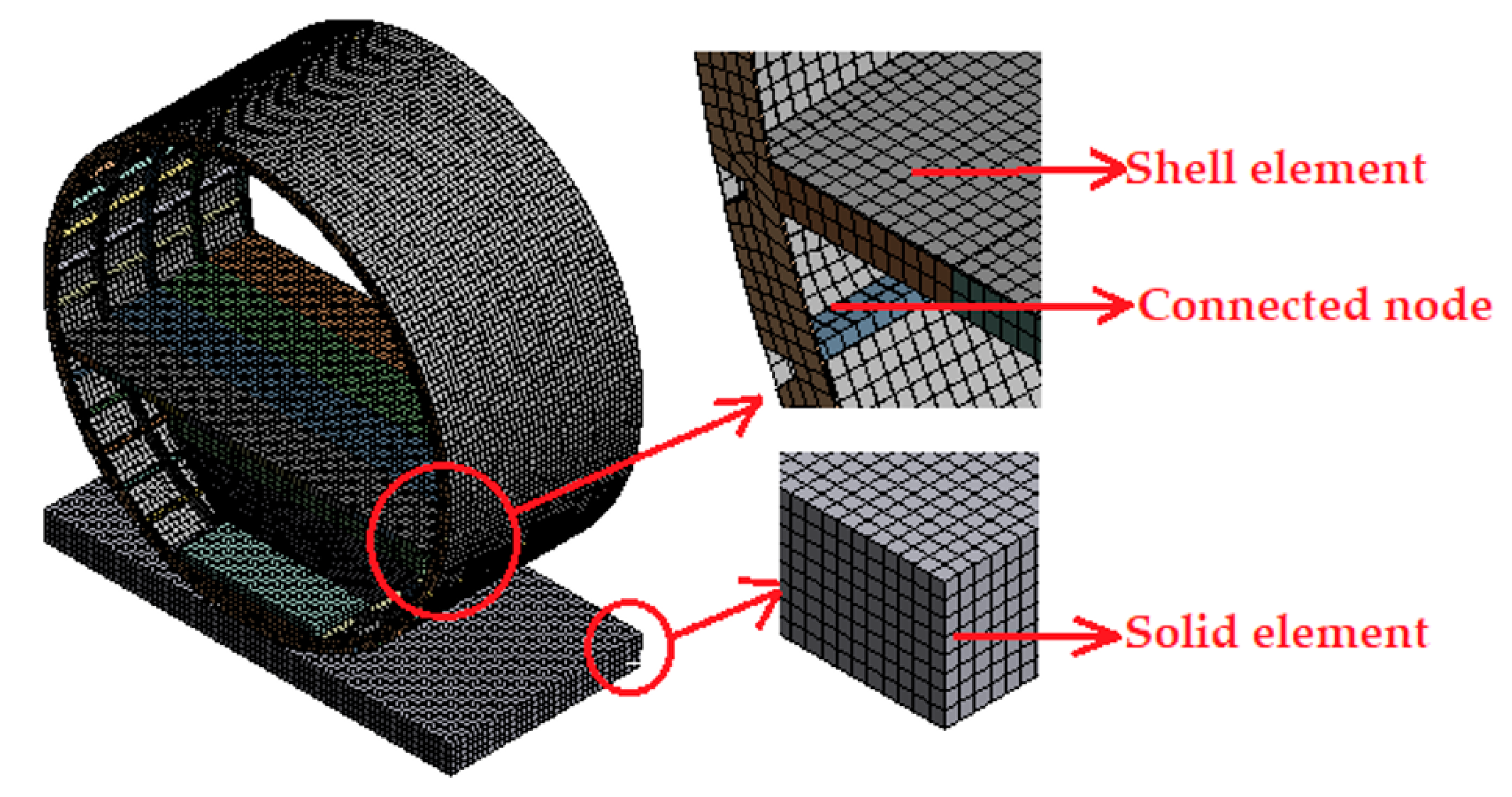
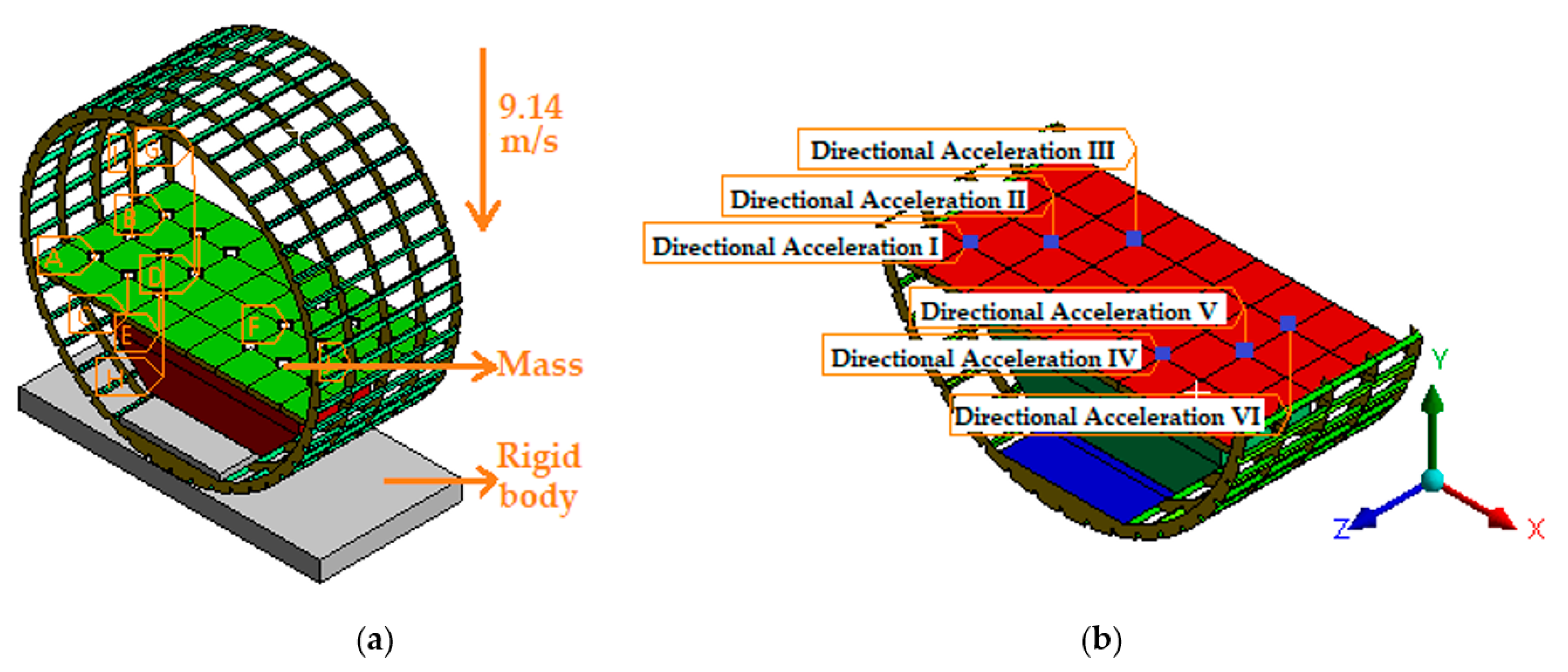
3.2. Mesh Generation and Boundary Condition

For impact case studies of thin-walled sections, quadrilateral shell elements are always preferred over triangular shell and solid elements [36]. Therefore, for the current investigation, all the thin-walled components, such as the fuselage skin, ribs, stringers, fuel tank, etc., were modeled with quadrilateral shell elements with an approximate size of 30 mm, which was found to be optimal for the present investigation. The total number of shell elements for traditional and reinforced fuselage sections were 64,551 and 67,071, respectively. In contrast, the solid bodies, namely, the crash floor, PVC foam block, and fuel were meshed with hexagonal brick elements, totaling the number 104,714. All the joints were properly examined to ensure the bonding of nodes. A complete illustration of the fuselage section with mesh generation is shown in Figure 2.
For the vertical drop test analysis, all the nodes of the fuselage section were assigned the recommended velocity of 9.14 m/s, along with the gravitation force [37]. The motion of the fuselage section was determined by six-degrees of freedom (6DOF), and the concrete crash floor was considered rigid while fixing all DOF. The concentrated mass of each seat and the dummy of 88 kg was distributed on the junction of the cabin floor and seat tracks (floor beam) [38], as shown in Figure 3a. The termination time was set to 0.15 s, which was found to be sufficient to capture the entire crash event until the complete rebound of the fuselage section. Moreover, to measure the acceleration response on the seat tracks, six different locations were chosen, as illustrated in Figure 3b. The acceleration data were filtered with a 48 Hz Butterworth low-pass filter [39].

4. Results and Discussion

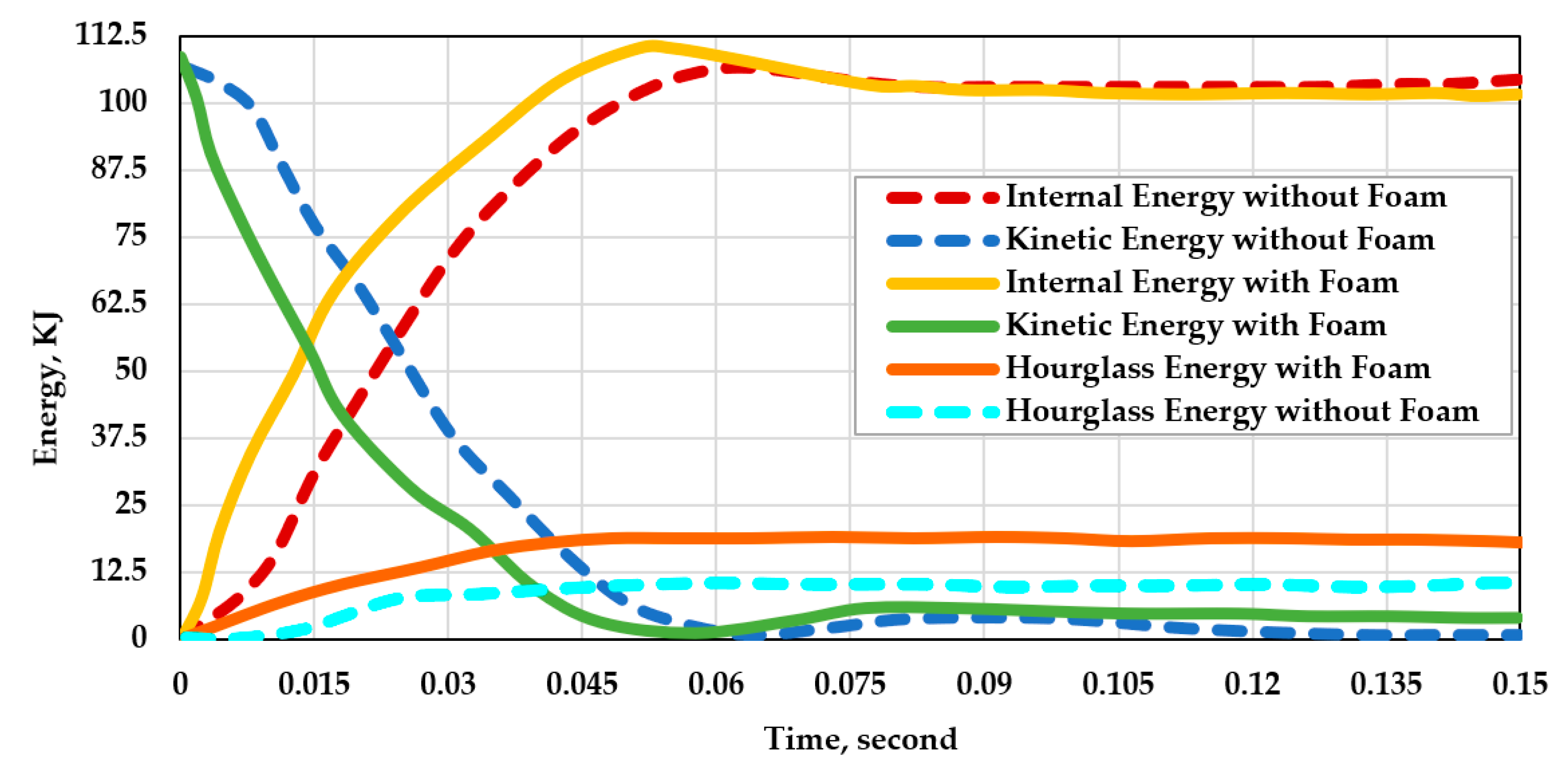
4.1. Energy Balance Graph

At first, the numerical energy balance graph is examined, as shown in Figure 4, which provides the basis for reliable computational outcomes. From the illustration, it is apparent that the hourglass energy for the traditional fuselage section without foam reinforcement is 9.8% of the total internal energy absorbed by the section, which is within the recommended hourglass energy limit of 15% [40]. In the case of foam reinforcement, the hourglass energy is 16.65% of the total internal energy, which exceeds the recommended margin by 1.65%. It is noteworthy that the fuselage section crash test without the presence of fuel and foam structure is highly non-linear and the current investigation includes a large amount of fuel as the Lagrange-based fluid model and foam reinforcement on top of the regular simulation, which makes a numerical drop test much more complex than a typical one. Furthermore, for both drop cases, the kinetic energy is maximum at the beginning of the impact, which is mostly converted to internal energy as the simulations progressed, and a well-balanced energy conversion can be found throughout the impact events. Therefore, it can be concluded that the numerical outcomes are reliable and valid for further discussions.

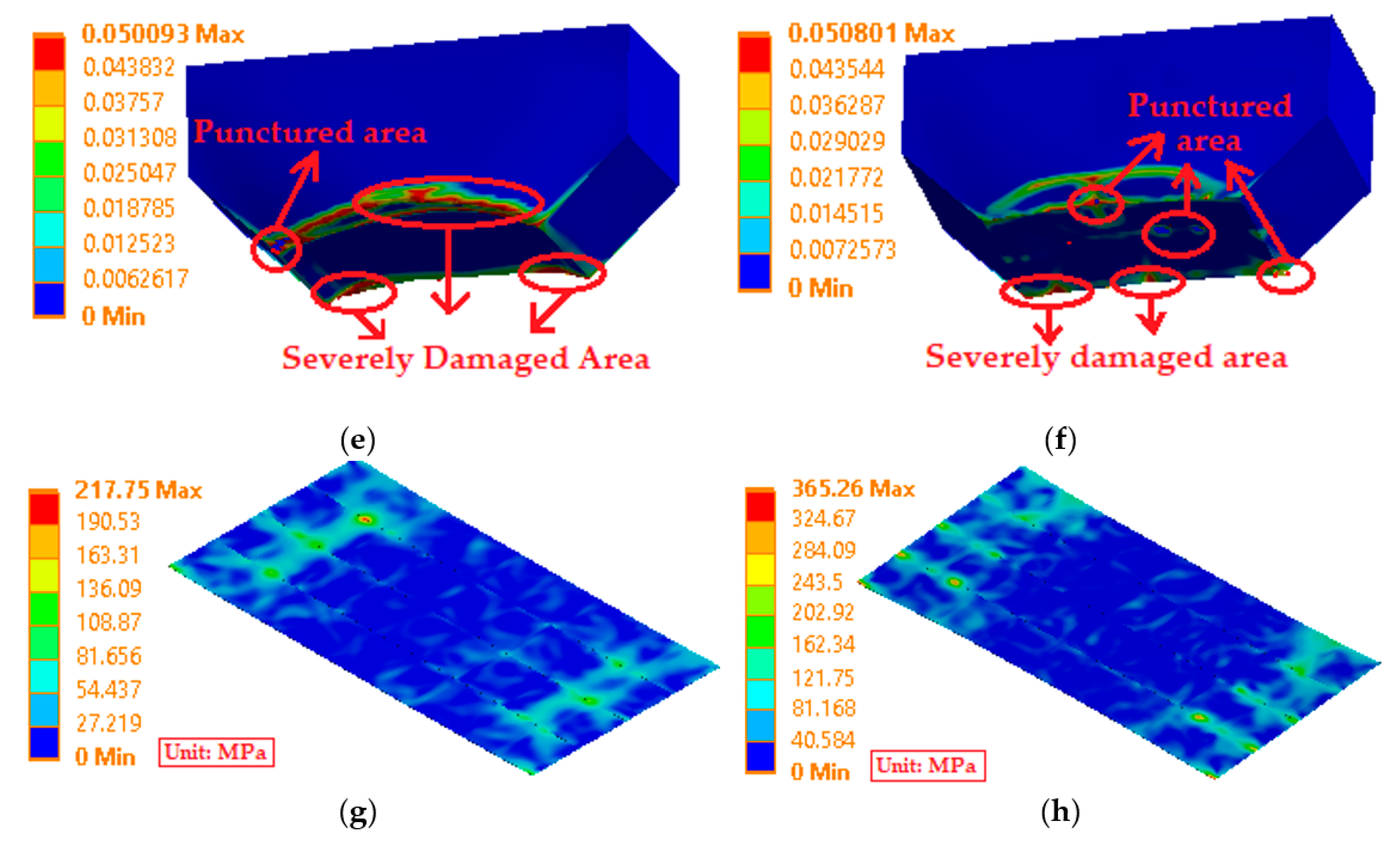
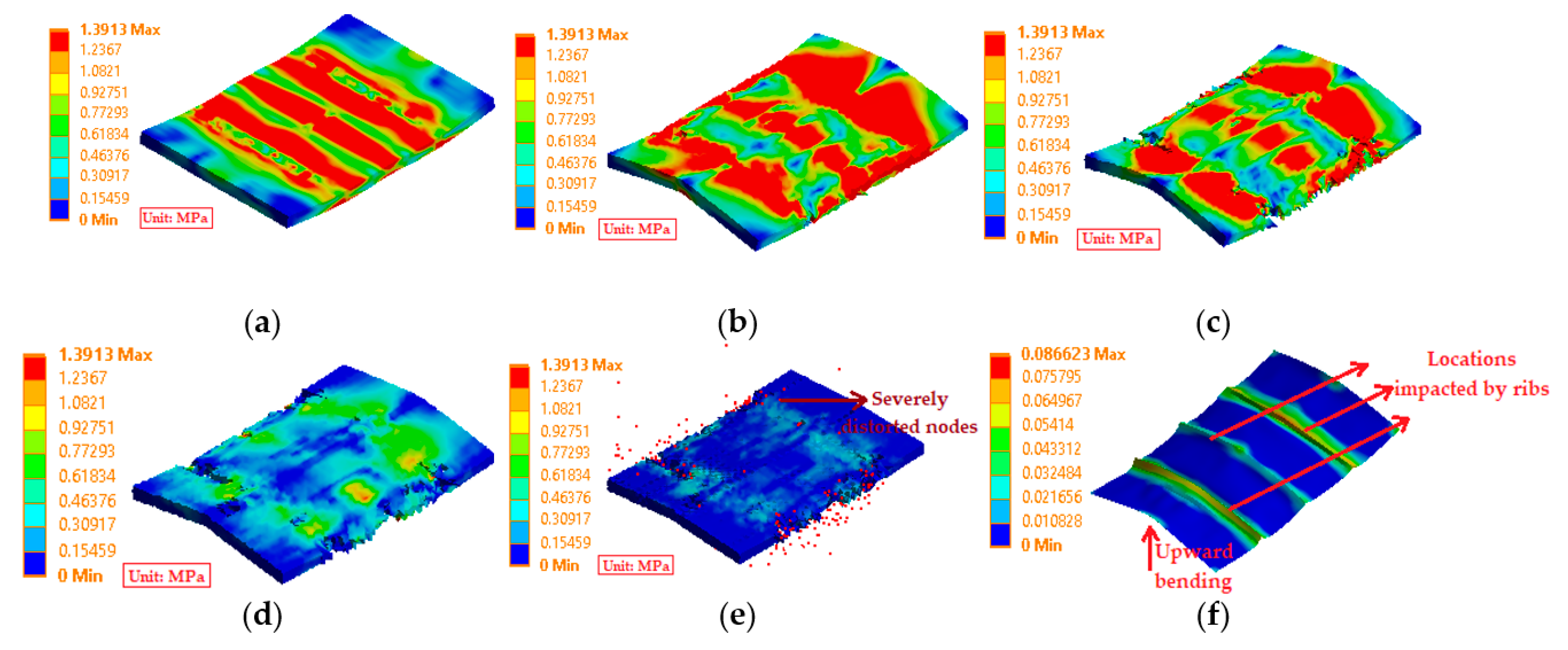
4.2. Energy Absorption and Plastic Deformation

Next, the energy absorption of the fuselage sections and the components, which refers to the amount of kinetic energy dissipated or absorbed during the vertical drop tests, is given in Table 4. From the computation, it is evident that the reinforced fuselage section generates a slightly higher amount of internal energy: to be exact, 3.54% higher than the traditional one. However, component-level energy absorption varies significantly between the two sections. In the case of foam reinforcement, it absorbs a significant portion of energy along with the plate, contributing a sum of 20% internal energy. However, this restricts the airframe to absorb only 36.10 KJ energy in comparison to the traditional fuselage section, where the airframe without reinforcement absorbs around 48% more internal energy. A similar trend is also observed for the fuselage skin. Nonetheless, due to the foam reinforcement, the fuel tank absorbs 41.16 KJ energy, which is 14.3% higher than the traditional one. Finally, in the presence of the reinforcement, the cabin floor needs to absorb a small amount of energy, only 1.12 KJ, whereas no reinforcement leads to an absorption of 4.10 KJ energy, contributing 3.8% of the total internal energy.
In terms of stress generation and damage analysis after plastic deformation, it can be seen that the maximum equivalent stress for the foam-reinforced fuselage section and traditional fuselage section is 406 MPa and 401.6 MPa, respectively, at the beginning of the impact, as illustrated in Figure 5a,b. However, by analyzing the post-crash photographs of effective plastic strain data, as shown in Figure 5c,d, it can be seen that the traditional fuselage section airframe suffers a significant amount of damage on the lower portion of the ribs along with the hinged area, whereas the reinforced one exhibits less damage, and some buckling is also observed. In the case of the fuel tank mounted in the reinforced fuselage section, it suffers severe damage, as well as punctures at the corner, as shown in Figure 5e. In contrast, the fuel tank with the traditional fuselage section experiences punctures at multiple locations, as shown in Figure 5f. However, the severely damaged area is less in contrast to the reinforced one. Finally, the maximum equivalent stress generated on the cabin floor surface can be seen in Figure 5g,h. Due to the reinforcement, the surface experiences only a maximum equivalent stress of 217.75 MPa at 0.06 s, which is approximately 41% lower than the value of the traditional section floor. However, for both sections, no plastic deformation is observed.
Stress generated during the entire impact event of the reinforced foam is illustrated in Figure 6a–e. At the beginning of the impact, the foam experiences the maximum stress at locations where the ribs are located, and, at 0.03 s, the foam bends upward, while the stress wave travels toward the longitudinal ends of the foam. At 0.057 s, the foam starts to tear up at several locations due to excessive compressive loading, and this trend continues before, finally, the foam gets compressed, and several eroded nodes are found in red dots at 0.15 s. These nodes are eroded due to the excessive deformation experienced by the foam and were removed by the solver to stabilize the entire solution process. Figure 6f represents the plastic deformation of the aluminum plate, which is severely deformed at the locations where the ribs impact during the crash test. In addition, it bends upward in the middle, similar to the foam structure.
Finally, the post-crash photographs of the fuselage sections can be seen in Figure 7. Despite having modeling differences, both the reinforced fuselage section and traditional fuselage section have similar plastic-hinged developments in the locations of the experimental test articles of the Boeing 737 fuselage with an onboard auxiliary fuel tank [41]. However, a closer look reveals that the traditional fuselage section is tilted on the right side after the crash, which is identical to the experimental one. In contrast, the crash event is more symmetrical, and no tilted section is observed in the case of the reinforced fuselage section.

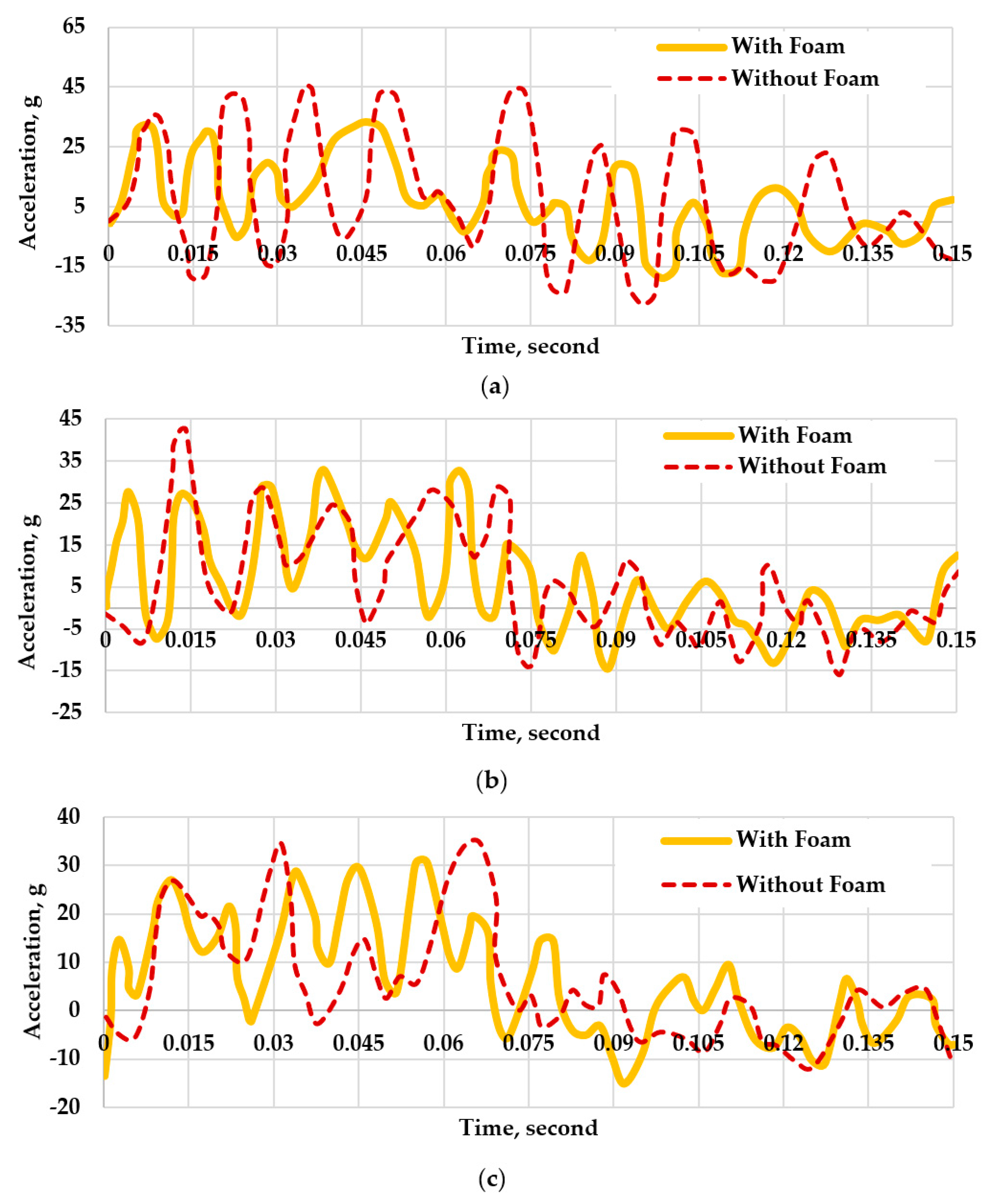
4.3. Acceleration Responses

The recorded acceleration responses on the selected nodes for both traditional and reinforced fuselage sections are illustrated in Figure 8, and the summary of the peak acceleration responses is given in Table 5. For node I [Figure 8a], the reinforcement softens the overall acceleration pulses significantly and reduces the highest peak by 27.08%. For node II, as illustrated in Figure 8b, the first peak acceleration, which is also the highest peak acceleration, experienced by the traditional fuselage is reduced by 35.3% by adopting the foam. However, at approximately 0.4 s, the slightly higher peak value 32.7 g is observed for the foam reinforcement, which remains 23.14% lower than the traditional highest peak response. For node III [Figure 8c], the acceleration peak at the beginning of the impact, at 0.015 s, to be exact, is identical for both fuselage sections. However, as time progresses, the peak values are considerably reduced for the foam-reinforced fuselage section. At 0.03 s, the value is reduced by 16.74%, and, finally, the maximum peak is reduced by around 11%.
In the case of node IV, as illustrated in Figure 8d, it exhibits an initial peak value of 27.20 g at the beginning of the impact due to the foam reinforcement. Nonetheless, at 0.015 s, when the traditional fuselage section experiences the highest peak value of 40.5 g, the foam-reinforced section encounters the highest peak value of 33.62 g, which is 16.9% lower than the traditional one. Despite that, the foam reinforcement suffers another two notable peak accelerations of 31.89 g and 33.61 g at 0.0375 s and 0.0618 s, respectively. Despite having some differences, for nodes V and VI, as illustrated in Figure 8e,f, they exhibit similar patterned acceleration responses for both the fuselage sections. For node V, the highest peak acceleration for foam reinforcement is observed at 0.043 s, which is 31 g, and, for the traditional one, a slightly higher peak acceleration of 33 g is noted at 0.052 s. Finally, for node VI, the highest peak accelerations recorded at around 0.05 s are 44.31 g and 28.33 g for traditional and reinforced sections, respectively. It is noteworthy that foam reinforcement reduced the highest peak value by around 36%.

5. Conclusions

A civil aircraft fuselage section with an auxiliary fuel tank was reinforced with a foam structure to improve the crashworthiness metrics of the fuselage during a vertical drop test. The non-linear explicit code Ansys Autodyn was adopted to run the tests virtually. Based on the numerical outcomes, the major conclusions were outlined as follows:
  • Reinforcement of the foam introduced solid elements to the simulation, and, in addition to the fuel model, the simulation further complicated and generated an hourglass energy of 16.65% of the total internal energy. Despite that, the overall kinetic to internal energy conversion confirmed the validity of the present numerical outcomes.
  • Due to the reinforcement, the overall energy absorption of the traditional fuselage model was improved by a margin of 3.54%. Moreover, the reinforced foam and aluminum plate contributed to a 20% absorption of the kinetic energy.
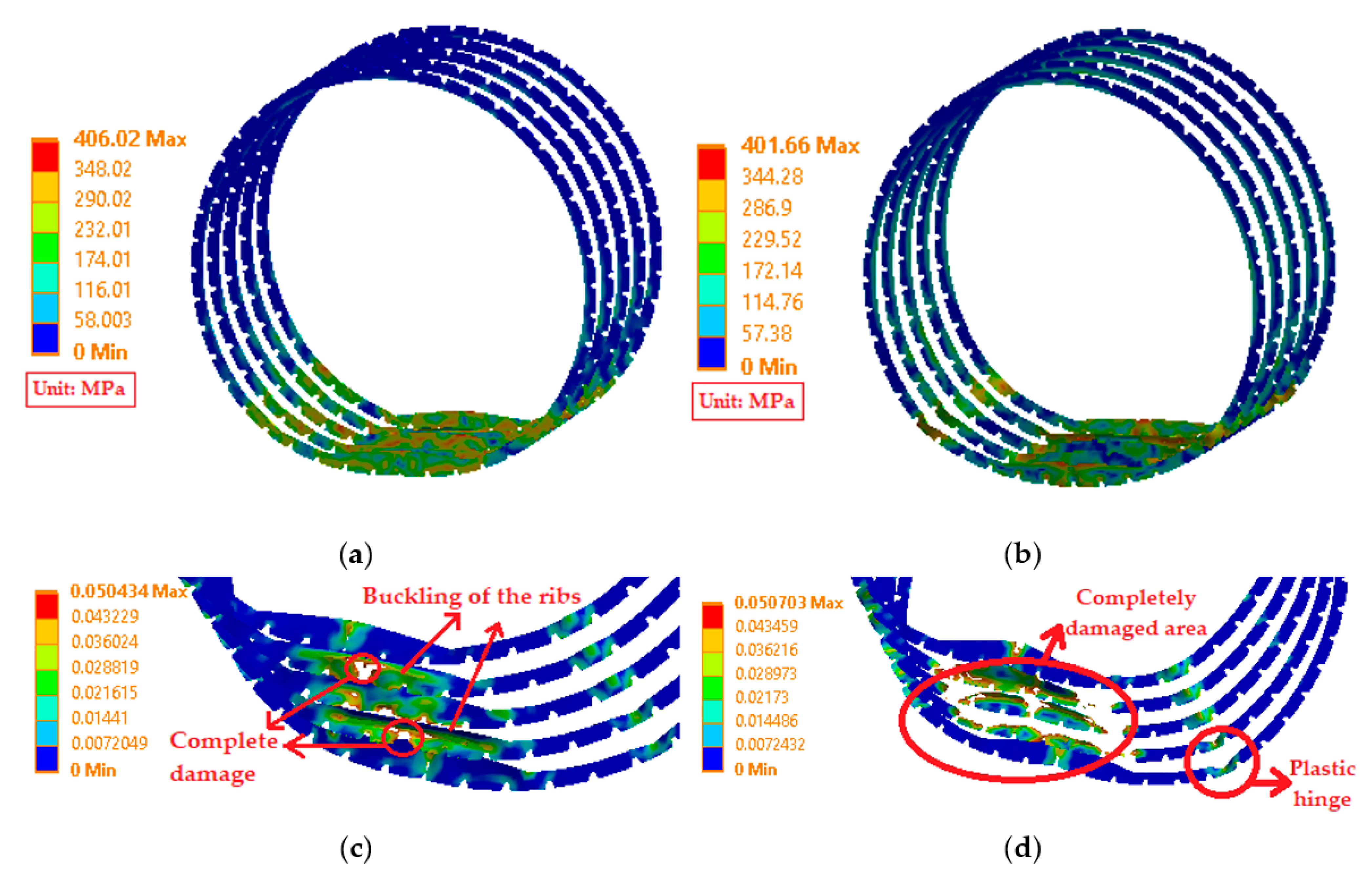
  • The structural damage of the rib section was significantly improved by adding the reinforcement. Nonetheless, this restricted the frame structure to absorb 36.10 KJ kinetic energy, in contrast to 54.60 KJ of the traditional one.
  • For both cases, the fuel tank experienced severe deformations, multiple punctures, and damaged areas. However, the energy absorption capability of the fuel tank mounted in the reinforced section was further increased by 14.3% (from 36.01 KJ to 41.16 KJ).
  • The cabin floor surface experienced a 41% lower maximum stress during the vertical impact in the case of foam reinforcement. More importantly, the seat trail acceleration responses were mitigated significantly, especially in the case of maximum peak acceleration outcomes. For all the locations considered, the highest peak values decreased from 6% to 36%, which suggested lower acceleration pulses experienced by the occupants.
In summary, despite some limitations, the proposed reinforced design had notably improved the crashworthiness of the fuselage section, especially the occupant’s safety, which was the primary concern of the crashworthiness study. Future research based on the composite fuselage and foam material variations is planned with an Eiband Diagram to rate the injury of the occupant.

Author Contributions

Conceptualization, S.B.R. and X.P.; methodology, S.B.R.; software, S.B.R.; validation, S.B.R. and X.P.; formal analysis, S.B.R.; investigation, S.B.R.; writing—original draft preparation, S.B.R.; writing—X.P.; supervision, X.P.; funding acquisition, X.P. All authors have read and agreed to the published version of the manuscript.

Funding

The authors gratefully acknowledge the financial supports from National Natural Science Foundation of China under Grants 12272319 and 12072288.

Data Availability Statement

Computational data were generated at the Impact dynamics lab facility at Northwestern Polytechnical University. Software data supporting the findings of this study are available from the corresponding authors on request.

Conflicts of Interest

The authors declare no conflict of interest.

References

  1. Tay, Y.Y.; Flores, P.; Lankarani, H. Crashworthiness Analysis of an Aircraft Fuselage Section with an Auxiliary Fuel Tank Using a Hybrid Multibody/Plastic Hinge Approach. Int. J. Crashworth. 2019, 25, 95–105. [Google Scholar] [CrossRef]
  2. Jackson, K.E.; Fasanella, E.L. Crash Simulation of Vertical Drop Tests of Two Boeing 737 Fuselage Sections; NASA: Washington, DC, USA, 2002. Available online: https://www.tc.faa.gov/its/worldpac/techrpt/ar02-62.pdf (accessed on 5 January 2023).
  3. Jackson, K.E.; Fasanella, E.L. Crash Simulation of a Vertical Drop Test of a Commuter-Class Aircraft. Int. J. Crashworth. 2005, 10, 173–182. [Google Scholar] [CrossRef] [Green Version]
  4. Kumakura, I.; Minegishi, M.; Iwasaki, K.; Shoji, H.; Miyaki, H.; Yoshimoto, N.; Sashikuma, H.; Katayama, N.; Isoe, A.; Hayashi, T.; et al. Summary of Vertical Drop Tests of YS-11 Transport Fuselage Sections. SAE Trans. 2003, 112, 531–540. [Google Scholar]
  5. Minegishi, M.; Kumakura, I.; Iwasaki, K.; Shoji, H.; Yoshimoto, N.; Terada, H.; Sashikuma, H.; Isoe, A.; Yamaoka, T.; Katayama, N.; et al. Vertical Drop Test of a YS-11 Fuselage Section. J. Jpn. Soc. Aeronaut. Space Sci. 2003, 51, 354–363. (In Japanese) [Google Scholar] [CrossRef]
  6. Perfetto, D.; De Luca, A.; Lamanna, G.; Chiariello, A.; Di Caprio, F.; Di Palma, L.; Caputo, F. Drop Test Simulation and Validation of a Full Composite Fuselage Section of a Regional Aircraft. Procedia Struct. Integr. 2018, 12, 380–391. [Google Scholar] [CrossRef]
  7. Riccio, A.; Saputo, S.; Sellitto, A.; Russo, A.; Di Caprio, F.; Di Palma, L. An Insight on the Crashworthiness Behavior of a Full-Scale Composite Fuselage Section at Different Impact Angles. Aerospace 2019, 6, 72. [Google Scholar] [CrossRef] [Green Version]
  8. Caputo, F.; Lamanna, G.; Perfetto, D.; Chiariello, A.; Di Caprio, F.; Di Palma, L. Experimental and Numerical Crashworthiness Study of a Full-Scale Composite Fuselage Section. AIAA J. 2021, 59, 700–718. [Google Scholar] [CrossRef]
  9. Guida, M.; Marulo, F.; Abrate, S. Advances in Crash Dynamics for Aircraft Safety. Prog. Aerosp. Sci. 2018, 98, 106–123. [Google Scholar] [CrossRef]
  10. Mou, H.; Xie, J.; Feng, Z. Research Status and Future Development of Crashworthiness of Civil Aircraft Fuselage Structures: An Overview. Prog. Aerosp. Sci. 2020, 119, 100644. [Google Scholar] [CrossRef]
  11. Meng, F.X.; Zhou, Q.; Yang, J.L. Improvement of Crashworthiness Behaviour for Simplified Structural Models of Aircraft Fuselage. Int. J. Crashworth. 2009, 14, 83–97. [Google Scholar] [CrossRef]
  12. Schatrow, P.; Waimer, M. Investigation of a Crash Concept for CFRP Transport Aircraft Based on Tension Absorption. Int. J. Crashworth. 2014, 19, 524–539. [Google Scholar] [CrossRef]
  13. Schatrow, P.; Waimer, M. Crash Concept for Composite Transport Aircraft Using Mainly Tensile and Compressive Absorption Mechanisms. CEAS Aeronaut. J. 2016, 7, 471–482. [Google Scholar] [CrossRef]
  14. Ren, Y.; Xiang, J. Improvement of Aircraft Crashworthy Performance Using Inversion Failure Strut System. Aircr. Eng. Aerosp. Technol. 2017, 89, 330–337. [Google Scholar] [CrossRef]
  15. Ren, Y.; Zhang, H.; Xiang, J. A Novel Aircraft Energy Absorption Strut System with Corrugated Composite Plate to Improve Crashworthiness. Int. J. Crashworth. 2017, 23, 1–10. [Google Scholar] [CrossRef]
  16. Mou, H.L.; Zou, T.C.; Feng, Z.Y.; Xie, J. Crashworthiness Analysis and Evaluation of Fuselage Section with Sub-Floor Composite Sinusoidal Specimens. Lat. Am. J. Solids Struct. 2016, 13, 1186–1202. [Google Scholar] [CrossRef] [Green Version]
  17. Ren, Y.; Xiang, J.; Zheng, J.; Luo, Z. Crashworthiness Analysis of Aircraft Fuselage with Sine-Wave Beam Structure. Chin. J. Aeronaut. 2016, 29, 403–410. [Google Scholar] [CrossRef] [Green Version]
  18. Heimbs, S.; Strobl, F.; Middendorf, P.; Guimard, J.M. Composite Crash Absorber for Aircraft Fuselage Applications. Available online: https://www.witpress.com/elibrary/wit-transactions-on-the-built-environment/113/21375 (accessed on 5 January 2023).
  19. Heimbs, S.; Strobl, F.; Middendorf, P. Integration of a Composite Crash Absorber in Aircraft Fuselage Vertical Struts. Int. J. Veh. Struct. Syst. 2011, 3, 87. [Google Scholar] [CrossRef]
  20. Zou, T.; Mou, H.; Feng, Z. Research on Effects of Oblique Struts on Crashworthiness of Composite Fuselage Sections. J. Aircr. 2012, 49, 2059–2063. [Google Scholar] [CrossRef]
  21. Feng, Z.; Mou, H.; Zou, T.; Ren, J. Research on Effects of Composite Skin on Crashworthiness of Composite Fuselage Section. Int. J. Crashworth. 2013, 18, 459–464. [Google Scholar] [CrossRef]
  22. Wang, T.; An, J.; He, H.; Wen, X.; Xi, X. A Novel 3D Impact Energy Absorption Structure with Negative Poisson’s Ratio and Its Application in Aircraft Crashworthiness. Compos. Struct. 2021, 262, 113663. [Google Scholar] [CrossRef]
  23. Heimbs, S. Energy Absorption in Aircraft Structures. 2012. Available online: http://www.heimbs-online.de/Heimbs_2012_IWHEM.pdf (accessed on 5 January 2023).
  24. Li, Q.M.; Mines, R.A.W.; Birch, R.S. The Crush Behaviour of Rohacell-51WF Structural Foam. Int. J. Solids Struct. 2000, 37, 6321–6341. [Google Scholar] [CrossRef]
  25. Jackson, K.E.; Fasanella, E.L.; Kellas, S. Development of a Scale Model Composite Fuselage Concept for Improved Crashworthiness. J. Aircr. 2001, 38, 95–103. [Google Scholar] [CrossRef]
  26. Zheng, J.; Xiang, J.; Luo, Z.; Ren, Y. Crashworthiness Design of Transport Aircraft Subfloor Using Polymer Foams. Int. J. Crashworth. 2011, 16, 375–383. [Google Scholar] [CrossRef]
  27. Ren, Y.; Xiang, J. Energy Absorption Structures Design of Civil Aircraft to Improve Crashworthiness. Aeronaut. J. 2014, 118, 383–398. [Google Scholar] [CrossRef]
  28. Paz, J.; Díaz, J.; Romera, L. Crashworthiness Analysis and Enhancement of Aircraft Structures under Vertical Impact Scenarios. J. Aircr. 2020, 57, 3–12. [Google Scholar] [CrossRef]
  29. Paz Mendez, J.; Díaz Garcia, J.; Romera Rodriguez, L.E.; Teixeira-Dias, F. Crashworthiness Study on Hybrid Energy Absorbers as Vertical Struts in Civil Aircraft Fuselage Designs. Int. J. Crashworth. 2019, 25, 430–446. [Google Scholar] [CrossRef]
  30. Adams, A.; Lankarani, H.M. A Modern Aerospace Modeling Approach for Evaluation of Aircraft Fuselage Crashworthiness. Int. J. Crashworth. 2003, 8, 401–413. [Google Scholar] [CrossRef]
  31. Fasanella, E.; Jackson, K.; Jones, Y.; Frings, G.; Vu, T. Crash Simulation of a Boeing 737 Fuselage Section Vertical Drop Test; NASA: Washington, DC, USA, 2004. Available online: https://ntrs.nasa.gov/citations/20040086069 (accessed on 5 January 2023).
  32. Byar, A. A Crashworthiness Study of a Boeing 737 Fuselage Section. Ph.D. Thesis, Drexel University, Philadelphia, PA, USA, 2003. [Google Scholar]
  33. Jackson, K.E.; Fasanella, E.L. Test-Analysis Correlation of a Crash Simulation of a Vertical Drop Test of a Commuter-Category Aircraft; NASA: Washington, DC, USA, 2004. Available online: https://ntrs.nasa.gov/citations/20040191338 (accessed on 5 January 2023).
  34. Rayhan, S.B.; Pu, X.; Huilong, X. Modeling of Fuel in Aircraft Crashworthiness Study with Auxiliary Fuel Tank. Int. J. Impact Eng. 2023, 173, 104449. [Google Scholar] [CrossRef]
  35. Ansys, Inc. Ansys Material Library; Ansys, Inc.: Canonsburg, PA, USA, 2021. [Google Scholar]
  36. Fasanella, E.; Jackson, K. Best Practices Simulation for Crash Modeling; NASA: Washington, DC, USA, 2002. Available online: https://ntrs.nasa.gov/citations/20020085101 (accessed on 5 January 2023).
  37. Tay, Y.Y.; Bhonge, P.S.; Lankarani, H.M. Crash Simulations of Aircraft Fuselage Section in Water Impact and Comparison with Solid Surface Impact. Int. J. Crashworth. 2015, 20, 464–482. [Google Scholar] [CrossRef]
  38. Mou, H.; Zou, T.; Feng, Z.; Ren, J. Crashworthiness Simulation Research of Fuselage Section with Composite Skin. Procedia Eng. 2014, 80, 59–65. [Google Scholar] [CrossRef] [Green Version]
  39. Hernández, S.; De Wilde, W.P.; Sejnoha, M. High Performance and Optimum Design Structure and Materials IV; Wit Press: Southampton, UK, 2020; pp. 127–138. ISBN 9781784663896. Available online: https://www.witpress.com/books/978-1-78466-389-6 (accessed on 5 January 2023).
  40. Muñoz, G.A. Crash Analysis with RADIOSS. Altair. 2015, pp. 203–205. Available online: https://www.academia.edu/26052761/Crash_Analysis_with_RADIOSS (accessed on 5 January 2023).
  41. Abramowitz, A.; Vu, T.; Smith, T. Vertical Drop Test of a Narrow-Body Transport Fuselage Section with a Conformable Auxiliary Fuel Tank Onboard, FAA. 2000. Available online: https://rosap.ntl.bts.gov/view/dot/42293 (accessed on 5 January 2023).
Figure 1. Geometric model of the fuselage section: (a) Traditional design; (b) Proposed reinforced design; (c) Skeleton view of the proposed model with aluminum plate; (d) Front view of the proposed model.
Aerospace 10 00314 g001
Figure 2. Mesh generation on fuselage section.
Aerospace 10 00314 g002
Figure 3. Numerical setup: (a) Boundary condition; (b) Location to record acceleration response.
Aerospace 10 00314 g003
Figure 4. Numerical energy balance graph.
Aerospace 10 00314 g004
Figure 5. Maximum equivalent stress and damage configuration: (a) Maximum equivalent stress of reinforced airframe at 0.015 s; (b) Maximum equivalent stress of traditional airframe section at 0.015 s, (c) Effective plastic strain of reinforced airframe, (d) Effective plastic strain of traditional airframe, (e) Effective plastic strain of fuel tank (reinforced); (f) Effective plastic strain of fuel tank (traditional); (g) Maximum Equivalent Stress of cabin floor (reinforced); (h) Maximum Equivalent Stress of the cabin floor (traditional).
Aerospace 10 00314 g005aAerospace 10 00314 g005b
Figure 6. Maximum stress and damage configuration: (a) Foam at 0.003 s; (b) Foam at 0.03 s; (c) Foam at 0.057 s; (d) Foam at 0.1 s; (e) Final damage of foam at 0.015 s; (f) Effective plastic strain of Al plate.
Aerospace 10 00314 g006
Figure 7. Post-crash front view of the fuselage sections: (a) Reinforced fuselage; (b) Experimental Boeing 737 fuselage [41] (c) Traditional fuselage for the present study.
Aerospace 10 00314 g007
Figure 8. Acceleration responses on the cabin floor: (a) Node I; (b) Node II; (c) Node III; (d) Node IV; (e) Node V; (f) Node VI.
Aerospace 10 00314 g008aAerospace 10 00314 g008b
Table 1. Mechanical properties of Aluminum Alloy [33].
Alloy VariantDensity,
ρ
(kg·m−3)
Young’s Modulus, E (GPa)Poisson’s Ratio, υYield Stress,
σ y , (MPa)
Tangent Modulus, EH
(MPa)
Failure Strain, εult, %
2024-T3276066.330.33243826.714.63
7075-T6279471.020.333601001.84.49
Table 2. Polynomial EOS of water [35].
Density ,
ρ
(kg·m−3)
A1
(GPa)
A2
(GPa)
A3
(GPa)
B0B1T1 (GPa)T2 (GPa)
10002.29.5414.570.280.282.20
Table 3. Composite PVC Foam material parameters [35].
Density,
ρ
(kg·m−3)
Young’s Modulus, E (MPa)Poisson’s Ratio, υOrthotropic Stress Limit
Tensile Stress, σ x = σ y
(MPa)
Tensile Stress,
σ z
(MPa)
Compressive Stress, σ x = σ y
(MPa)
Compressive Stress,
σ z
(MPa)
Shear Stress,
τ x y = τ y z = τ z x
(MPa)
801020.32.21.5−2.2−1.51.35
Table 4. Energy absorption by the components.
Fuselage TypeTotal Energy, KJFoam, KJAluminum Plate, KJFuselage Skin, KJAirframe, KJFuel Tank with Fuel, KJCabin Floor with Beam, KJ
Reinforced with Foam
Absorption
Percentage
110.1617.1755.0410.5836.1041.161.12
-15.5%4.5%9.6%32.7%37.3%1%
Traditional Fuselage Section
Absorption Percentage
106.39--14.9653.4036.014.10
---13.9%49.7%33.5%3.8%
Table 5. Highest Peak Acceleration Responses.
Node No.Highest Peak Acceleration, g
(Traditional)
Highest Peak Acceleration, g
(Reinforced)
Peak Acceleration IncreasedAerospace 10 00314 i001
/Decreased Aerospace 10 00314 i002 for Reinforcement, %
145.6333.2727.08 Aerospace 10 00314 i002
242.55 32.7023.14 Aerospace 10 00314 i002
334.4730.6511.08 Aerospace 10 00314 i002
440.533.6216.96 Aerospace 10 00314 i002
533316.00 Aerospace 10 00314 i002
644.3128.3336.06 Aerospace 10 00314 i002
Disclaimer/Publisher’s Note: The statements, opinions and data contained in all publications are solely those of the individual author(s) and contributor(s) and not of MDPI and/or the editor(s). MDPI and/or the editor(s) disclaim responsibility for any injury to people or property resulting from any ideas, methods, instructions or products referred to in the content.

