Article

Functional Hazard Assessment of a Modular Re-Configurable Morphing Wing Using Taguchi and Finite Element Methodologies

Department of Aerospace Engineering, Toronto Metropolitan University, Toronto, ON M5B 2K3, Canada
*
Author to whom correspondence should be addressed.
Aerospace 2023, 10(3), 300; https://doi.org/10.3390/aerospace10030300
Submission received: 3 February 2023 / Revised: 10 March 2023 / Accepted: 15 March 2023 / Published: 17 March 2023
(This article belongs to the Special Issue Morphing Aircraft)

Abstract

:
Growing concerns over the CO2 footprint due the exponential demand of the aviation industry, along with the requirements for high aerodynamic performance, cost saving, and manoeuvrability during different phases of a flight, pave the path towards adaptable wing design. Morphing wing design encompasses most, if not all, of the flight condition variations, and can respond interactively. However, functional failure of the morphing wing might bring devastating impacts on the passengers, crew, and/or aircraft. In the present work, the dynamic characteristics of a re-configurable modular morphing wing developed in-house by a research group at the Toronto Metropolitan University, are investigated from the perspective of a functional hazard assessment (FHA). This modular morphing wing, developed based on the idea of a parallel robot, consists of a number of structural elements connected to each other and to the wing ribs through eye-bolt joints. Timoshenko’s bending beam theory, in conjunction with the finite element method (FEM), is exploited to model the structural members. Possible hazards, assumed here to be the structural failure of the beam components, have been identified and their failure conditions are assessed. Numerical simulations have been presented to show the impact of various combinations of the identified hazards on the vibration signature of the morphing wing in unmorphed and morphed configurations. Identification of changes in the wing’s vibration signature is a vital component in the fail-safe structural and aeroelastic design of an aircraft. The present study is geared towards the structural response of the system in the absence of any aerodynamic loads.

1. Introduction

To meet the growing need, while keeping the devastating impact on the environment to minimum, the aviation industry is currently facing a plethora of challenges [1,2]. The research and production of green aircraft [1,3,4] are the logical outcomes and trends in compliance with the IATA legal requirements outlined in the technology roadmap set for future aircraft design [5,6]. Due to the inherent characteristics of reducing fuel consumption, morphing wing technology is regarded as an active research area towards environmentally friendly aircraft. In fact, it has been shown by Barbarino et al. [7] that approximately 3 to 5 percent fuel saving can be achieved through morphing wing aircraft.
Although still in the rudimentary stage, morphing wings offer adaptability during different flight phases and gust conditions. Morphing wings’ adaptability can be classified into two major categories: in-plane transformation (including sweep, span-wise expansion/contraction, and chord length variation) and out-of-plane transformation (dihedral/gull, twist, and span-wise bending). Span-wise morphing and sweep change the wing aspect ratio and thereby change the lift distribution and lift-to-drag ratio. The enhancement of the lift-to-drag ratio improves the range and endurance of the aircraft [8]. Furthermore, the sweep alters the longitudinal and lateral stability of the wing due to the relocation of the aerodynamic and gravity centres [9]. Dihedral morphing alters rolling stability. It can provide better agility, reduction in induced drag, and an improvement in stall characteristics [7]. It is widely accepted and agreed that hinged devices, such as flaps, ailerons, and slats are not considered morphing devices. In addition to the wing morphing described above, there is continuous extensive active research in the area of airfoil morphing. Chen et al. [10] designed and successfully implemented the control laws on a tensegrity morphing airfoil. However, their work is limited to the kinematic analysis and no dynamic analysis was presented. Interested readers are referred to the review papers published by Barbarino et al. [7], Ameduri and Concilio [11], Ajaj et al. [12], and Dhara et al. [13] for the structural and shape-changing morphing concepts applied to both fixed and rotary wing aircraft with special consideration of active systems, challenges and current issues related to morphing wing technology application, aeroelastic stability and control effects on the morphing wings of fixed-wing aircraft, and the evolution of morphing wing concepts, respectively.
It is of prime importance to optimize the morphing wing for conflicting multi-objectives of weight, aerodynamics, structure, and actuation [14]. Morphing imposes a cost on the system with the advantages they bring in. Table 1 below briefly highlights the advantages and challenges in terms of the cost of the system. This cost is generally associated with the morphing skin requirement to adapt the morphing mechanism and aerodynamic force distribution [15].
Most of the work on morphing wings is focused on the application and optimization of controllers and smart materials [16,17,18]. Some aeroelastic analysis has also been performed on a single morphing parameter of the morphing wing [19].
Besides bringing the above-mentioned prospects, due to the increased number of components and, therefore, more degrees of freedom, any hazard, considered here to be the damage to, or failure of beam components could lead to a drastic decline in the expected performance of the morphing wing. In the absence of any specific airworthiness certification standard for the morphing wing, designers need to exert extra effort in identifying the functional and fault hazards and their corresponding failure conditions. Damage in the function and/or components of a morphing wing may lead to drastic changes in the vibration signature of the wing for which the design was conceived and tested during the ground vibration test (GVT) for the airworthiness certification process. This would not only limit the aircraft operation in the vibration environment from aeroelastic perspectives, but could also lead to unavoidable nuisance conditions to the passengers and crew. Very limited work on the functional hazard assessment (FHA) is available on very simple winglet and aircraft design [20,21]. Based on the FHA and quantitative fault tree analysis on an isolated morphing winglet and the subsequent aeroelastic analysis, Noviello et al. [20] concluded that the failure of the actuator was more critical than that of the structural link. Proper damping devices were also suggested by the authors to avoid the aeroelastic instabilities. However, no detailed modal analysis of the wing–winglet system was presented in their work. Slawomir et al. [21] conducted FHA based on the possible failures of the structural health-monitoring system (SHM) of an unmanned aerial vehicle (UAV). Based on their presented FHA, they concluded that the failure of the SHM did not need any qualitative or quantitative analysis. Therefore, they did not present any structural and/or aeroelastic analysis of the system. To the best of authors’ knowledge, no comprehensive work on the FHA of morphing wings with regard to the system’s dynamic characteristics has been reported in the open literature. A considerable variation in the dynamic characteristics of the wing could potentially result in hazardous or even catastrophic failure conditions. Therefore, the probability of failure conditions must be determined qualitatively or quantitatively at the preliminary design stage. The scarcity of literature on FHA applied to morphing wing systems is the motivation behind the current study.
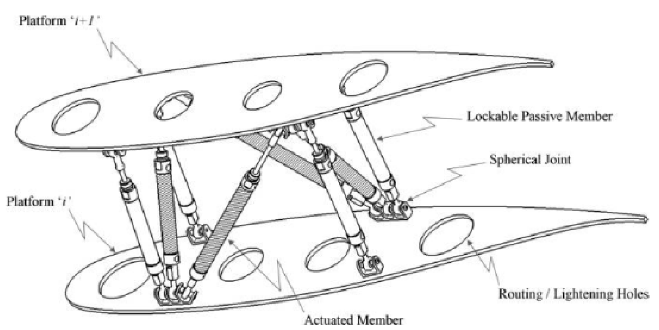
This paper presents a systematic approach to perform FHA on the preliminary design of a morphing wing, with the application to the wing conceived by Finistauri et al. [22], followed by Moosavian et al. [23], at the Toronto Metropolitan University (formerly Ryerson University). They successfully implemented the parallel robot manipulator concept in morphing wing design, which can adapt to span-wise, dihedral, sweep, and twist mechanisms simultaneously per the flight condition requirements. Their base design is modular in nature and the number of modules can be optimized based on mission requirements, which could eliminate the need for tedious tasks of recurring wing redesign. However, their work is limited to the kinematic-based design of the proposed morphing wing omitting any structural and/or aerodynamic analysis. In a more recent publication [24], the authors presented the free vibration analysis of un morphed (original) and morphed configurations of the above-mentioned wing design subjected to span-wise extensions. The results of systems’ free vibration analyses were validated against those obtained from FEM-based analysis and the dynamic stiffness matrix (DSM) method. The effect of various span-wise extensions as well as topology on a system’s natural frequencies were also studied and reported. In the present paper, the authors’ earlier work [24] has been extended to the structural dynamic analysis and qualitative FHA of the defective morphing wing. The defect is assumed to be the structural failure of the beam components and any chord length variations, sweep, out-of-plane transformations, and aerodynamic effects are excluded from the analysis.

2. Theoretical Treatise

2.1. Modular Morphing Wing Mechanism/Function Design

The morphing wing analysed in this study is modular in nature. Each module consists of eight load-bearing structural members and two wing ribs. Four of these load-bearing members are active, controlled by actuators, and the other four are passive. The optimal topological configuration, obtained through kinematic analysis, presented by Finistauri et al. and Moosavian et al. [22,23], are investigated here. Active structural members are connected diagonally to the others, as presented in the prototype and CAD model of the morphing wing (Figure 1). In each module, eight load-bearing structural members are connected to each other and to the wing ribs through spherical (eye-bolt) joints. The four active members, controlled by actuators, along with other four passive members and joints are shown by the mechanism in Figure 2. The spherical joints between members transmit only the linear motion along three coordinate axes. However, these joints do not resist the rotational motion between the members.
With the optimal design shown in Figure 1, various wing-morphing configurations can be achieved, including span-wise extension, dihedral, and sweep motion. A detailed procedure for achieving various morphing configurations has been outlined by Moosavian [25].

2.2. Governing Equations

In the present study, a two-module morphing wing is considered. Each load-bearing structural member in a module is modelled as a beam. Each beam is divided into several Timoshenko beam elements (Equations (1) and (2) with six degrees of freedom per node). The spherical (eye-bolt) joints between wing rib and load-bearing structural members (beams) are modelled as hinged joints in 3D to transmit only the linear motions along three coordinate axes, by suppressing the transfer of rotational motions between the connected structural members, and the following assumptions applied:
  • Wing ribs can be represented by five structural beam elements connecting the other eight beam/bars in each module.
  • Stiffness of the structural members representing wing ribs is assumed to be 1000 of that of the other active and passive structural members of the module.
  • All structural beams are initially straight and unstressed.
  • Plane section remains in-plane during bending, but no longer perpendicular to the neutral axis.
  • All structural elements are perfectly elastic, homogeneous and isotropic.
  • Upon span-wise expansion, the diameter of each structural member can be assumed uniform and computed based on the constant mass of the member.
For a constant cross-sectional area Timoshenko beam section in the x y plane, the differential equations governing the dynamics of the system are written as [26,27,28]:
G A κ s 2 v x 2 ϕ x = ρ A 2 v t 2 q ( x , t )
E I 2 ϕ x 2 + G A κ s v x ϕ = ρ I 2 ϕ t 2
where A, E, G, I, v, ϕ , and κ s are the cross-sectional area, modulus of elasticity, shear modulus, second area moment of inertia, lateral beam deflection in the y direction, flexural bending, and the shear correction factor, respectively. q is the applied load. Moreover, κ s A = A s is the shear area. κ s for the solid circular cross-section is 0.9.
Exploiting the standard finite element methodology (FEM) [29], the flexural stiffness matrix for a 2D Timoshenko beam element of length L can be written as follows:
[ k ] = E I L 3 ( 1 + ψ ) 12 6 L 12 6 L 6 L ( 4 + ψ ) L 2 6 L ( 2 ψ ) L 2 12 6 L 12 6 L 6 L ( 2 ψ L 2 ) 6 L ( 4 + ψ ) L 2
where ψ = 12 E I κ s A G L 2 .
The consistent mass matrix of the element, as also reported by Davis et al. [30], is written as:
m = ρ A [ X ] t [ H ] [ X ] ,
where [ H ] and [ X ] are
[ H ] = L 7 252 + γ ( L 5 20 + L 3 β 3 + L β 2 ) L 6 72 + γ ( L 4 8 + L 2 β 2 ) L 5 20 + γ L 3 3 S y m m e t r i c a l L 5 30 + γ ( L 3 6 + L ) L 4 8 + γ L 2 2 L 3 3 + γ L L 4 24 L 3 6 L 2 2 L ,
[ X ] = E I L 3 ( 1 + ψ ) 0 0 0 1 β 0 1 0 L 3 6 L 2 2 L 1 L 2 2 + β L 1 0 ,
with β = E I κ s A G and γ = I A . By ignoring shear deformation and rotary inertia, Timoshenko beams are reduced to Euler–Bernoulli beams.

2.3. Modal Analysis

Modal analysis is performed using an in-house code written based on the conventional FEM, where the equations of motion are written as:
[ M ] d ¨ + [ K ] d = 0 ,
where d is the displacement vector, with d i for the nodal DOFs written as:
d i = v i ϕ i
[ M ] and [ K ] are the global (assembled) mass and stiffness matrices of the system, respectively. For the sake of simplicity of the presentation, each node is assumed to have two DOF. Considering the following harmonic solutions ((9) and (10)) for governing Equations (1) and (2),
v = v o e i ω t
ϕ = ϕ o e i ω t .
and letting q = 0 , the linear eigenvalue problem (11) of the global assembled system is reached as:
[ K ω 2 M ] d = 0 .
Therefore, the circular natural frequency ω (eigenvalue) and corresponding mode shape (eigenvector) d can be obtained by solving the linear eigenvalue problem of the system (11).

3. Safety Assessment

Safety assessment is a comprehensive and systematic process of identifying hazards, and their classifications, establishing safety requirements, and verifying that these requirements are met to achieve a fail-safe aircraft and its systems’ design. This process runs throughout the development cycle of the aircraft. Safety assessment process is broadly divided into three stages: functional hazard assessment (FHA), preliminary system safety assessment (PSSA), and system safety assessment (SSA). FHA and PSSA are performed during the preliminary design phase of the aircraft, while SSA is executed during the detailed design phase. Therefore, PSSA generally necessitates a qualitative methodology tool, e.g., fault tree analysis (FTA). The morphing system in this work is in the preliminary design phase. Therefore, in what follows, only FHA and PSSA will be discussed further.

3.1. Functional Hazard Assessment, FHA

According to the guidelines and methods for conducting the safety assessment process on civil airborne systems and equipment, SAE-ARP4761 [31], a system is ‘a combination of inter-related items arranged to perform a specific function(s)’. The main purpose of FHA is to identify the hazards and classify their failure conditions. Failure conditions reflect the expected impact on the aircraft system(s), aircraft, passengers, and/or crew during flight phases due to detrimental operational or environmental effects [31]. Failure conditions are classified into four categories on the basis of the degree of their devastating impact on the aircraft safety and level of easiness to cope with them. These failure conditions, in the order of increasing degree of distress, include no safety effect (NSE), minor, major, hazardous and catastrophic. Descriptions of failure condition classifications are given in Table 2.
Qualitative, along with quantitative, probability categories, for the purpose of the aircraft system safety, are defined in Table 3.
According to the equipment, systems, and installation standard of transport category aircraft, 14CFR 25.1309(b) [33], The airplane systems and associated components, considered separately and in relation to other systems, must be designed so that:
  • The occurrence of any failure condition which would prevent the continued safe flight and landing of the airplane is extremely improbable, and
  • The occurrence of any other failure conditions which would reduce the capability of the airplane or the ability of the crew to cope with adverse operating conditions is improbable’.
Therefore, a single failure causing catastrophic failure conditions must be extremely improbable. Essentially, the objectives of 14CFR 25.1309(b) are to keep the probability of the failure conditions such that [32]:
  • The no safety effect has no probability requirement;
  • The minor failure condition may be probable;
  • The major failure condition must be remote;
  • The hazardous failure condition must be extremely remote;
  • The catastrophic failure condition must be extremely improbable.
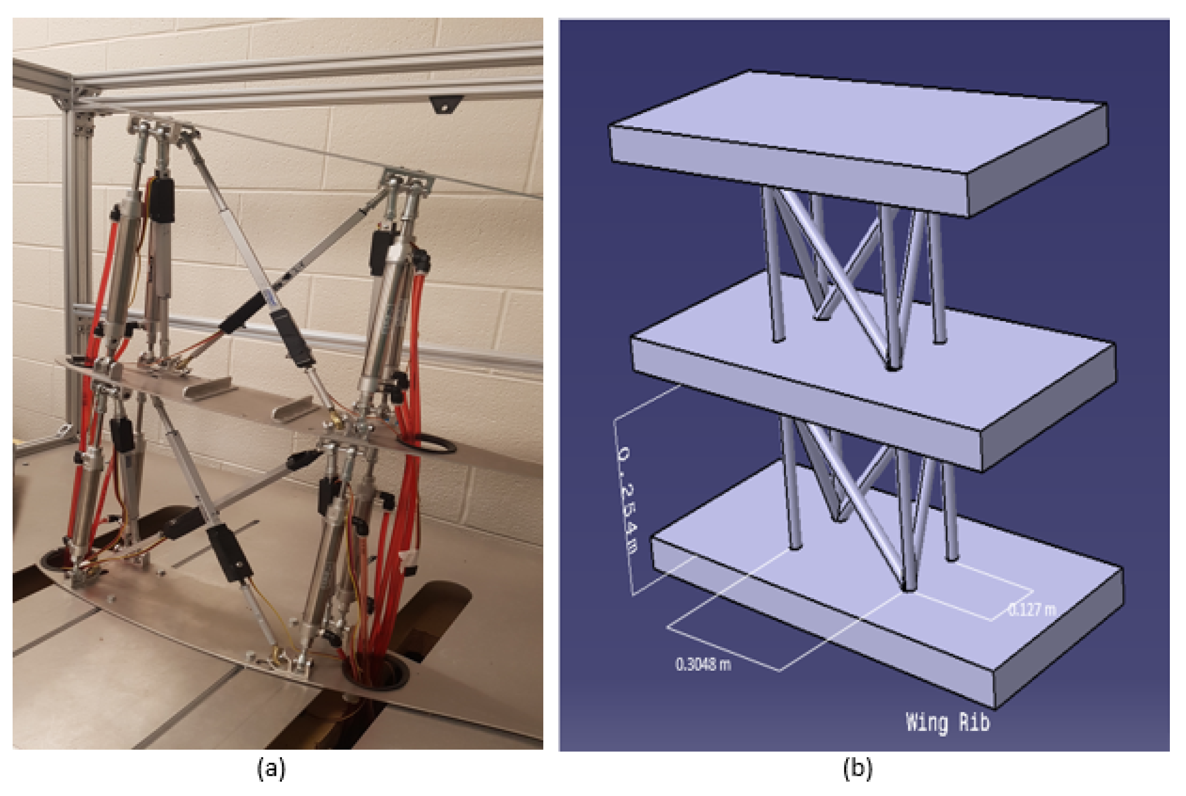
The modular morphing system presented here is a system composed of two re-configurable modules, each consisting of eight structural beams (four active and four passive) and the end ribs, each represented and modelled by a planar frame made of five rigid beams (i.e., 1000 times stiffer than the active and passive beams). Table 4 below presents the identified hazards and their respective failure conditions for the current modular morphing wing system.

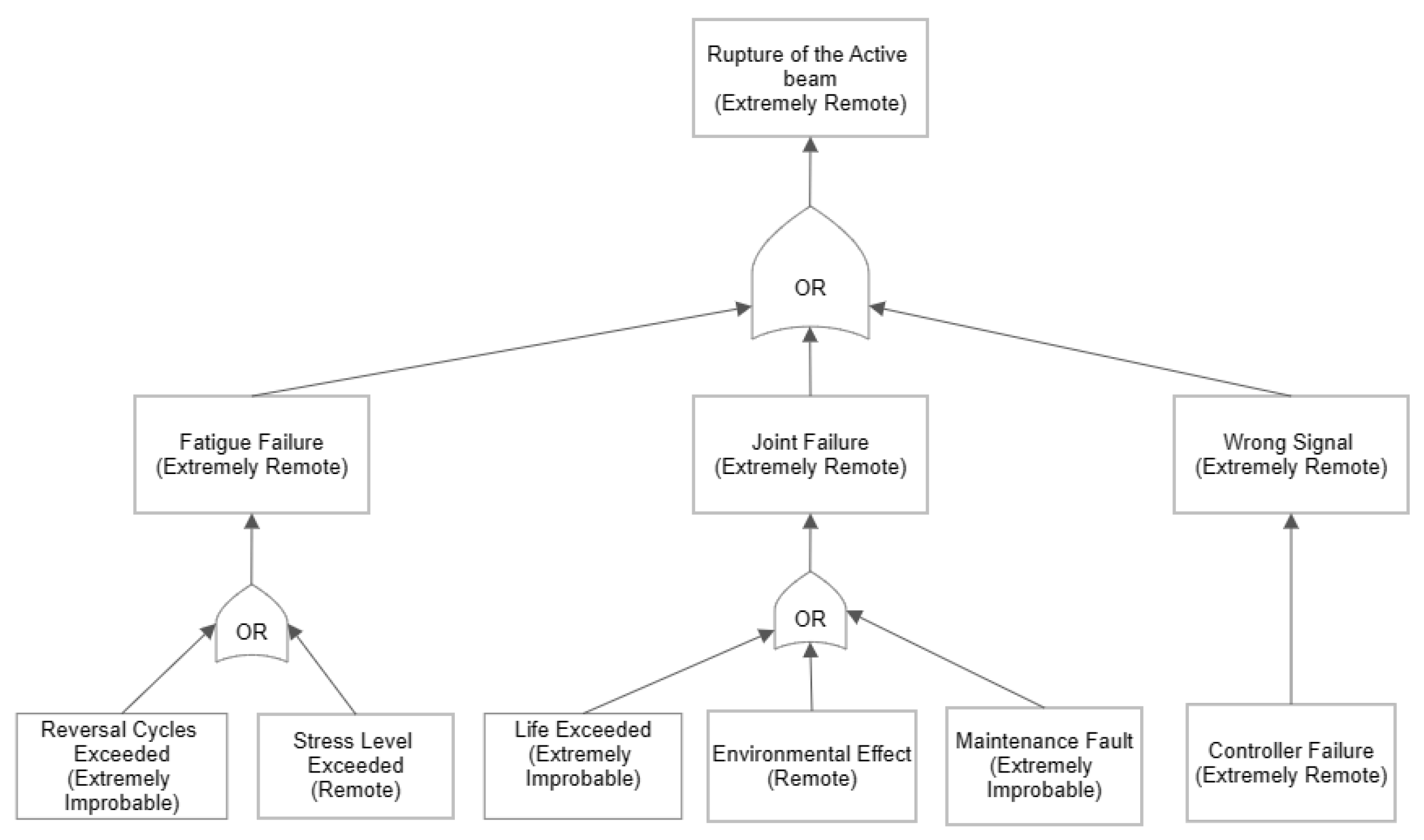
3.2. Qualitative Fault Tree Analysis, FTA

Due to the unavailability of the reliability data of the components used in the preliminary design of the current morphing wing, a qualitative fault tree analysis (FTA) has been deemed sufficient for the PSSA. Based on the results obtained through earlier simulations carried out by the authors and further discussions among the research team, it was deduced that the best suitable FTA can be presented as shown in Figure 3. This FTA clearly shows that the hazardous failure condition (i.e., case 1 in Table 4, active beam rupture) identified in this work is extremely remote, which is in compliance with the guidelines for safety assessment, as stated in SAE-ARP4761 [31].
Despite the fact that the hazardous failure condition (i.e., active beam rupture, in this case) is extremely remote, it is important to investigate the effects of such an unlikely event on the vibration signature of the system at hand. Any changes in the vibration signature could, in turn, potentially make the morphing wing’s response deviate from the intended design parameters, leading to structural damage, and/or hamper control of the system. Therefore, in the following section, the FEM-based simulations and vibration analysis of intact (benchmark) and defective (both unmorphed and span-wise morphed) systems are presented.

4. FEM-Based Numerical Investigation of the Failure Condition

As mentioned earlier in the paper, the wing’s structural members are treated as Timoshenko beams, with hinged joints. The detailed procedure of the FEM-based modal analysis is described in the authors’ earlier work [24] and has been omitted here for brevity.
As also stated before, the wing design consists of two modules: each one composed of eight structural beams and two ribs. Furthermore, each rib is modelled as a planar assembly of five rigid beams, i.e., there are 26 beams in total. Diameter of each beam in the unmorphed (benchmark) configuration is 0.0254 m (1 in). The distance between the two wing ribs, i.e., the unmorphed module length, is 0.254 m (10 in) (refer to Figure 1). Mechanical properties of structural beams (active and passive) are given in Table 5.
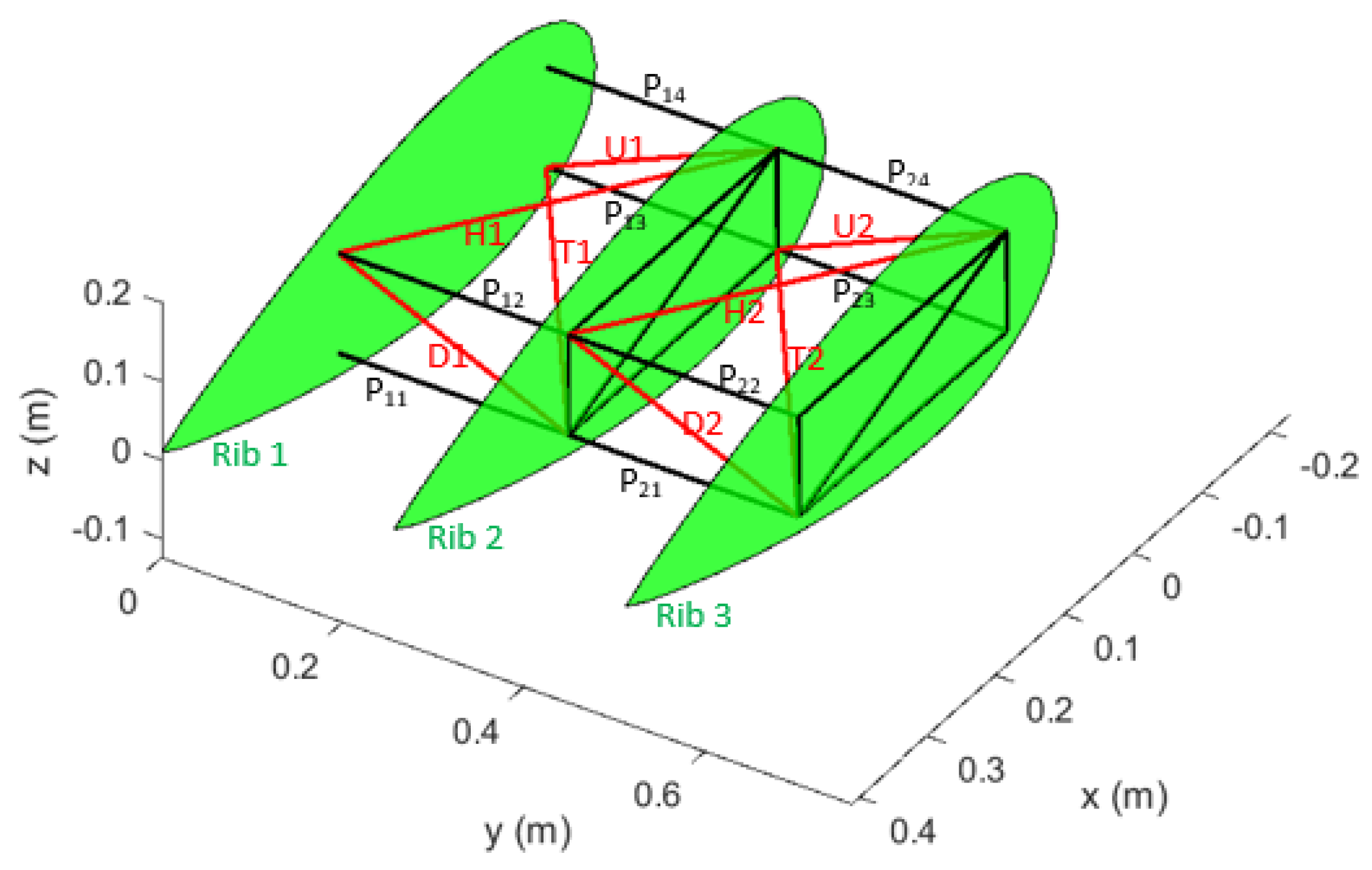
Hazards identified earlier are utilized here to investigate their respective anticipated impacts on the vibration characteristics of the morphing wing system. The four active beams per module, whose failures are identified as hazards, along with their locations are designated by symbols as presented in Table 6, and indicated in red (refer to Figure 4). The four passive members in each module are also depicted in Figure 4 in black, and are designated by symbols P i j . Here i and j represent the module number and the beam number, respectively.
Each active beam, considered as factors, has two levels to represent their functional status, as given in Table 7.
First, the benchmark case, i.e., intact system, with all the beams fully functional, in the unmorphed (original) wing configuration, is simulated for model analysis. The benchmark system’s first ten natural frequencies are given in Table 8.
Numerical simulations and experiments are then performed on the defective wing in its unmorphed (original) configuration to study the hazard assessment. For a complete factorial design of experiments, one needs to run a total of 2 8 = 256 simulations to investigate the effects of various combinations of eight factors, with two levels each. However, by exploiting the Taguchi technique, only 12 experiments were deemed sufficient to serve the purpose and achieve the same results. The details of the Taguchi technique can be found in references [34,35,36] and have been omitted here for brevity. The Taguchi orthogonal array (L12), obtained by using the designation of beams and the level identifiers as given in Table 6 and Table 7, is presented in Table 9.
The resulting first ten natural frequencies, corresponding to the 12 experiments, are given in 
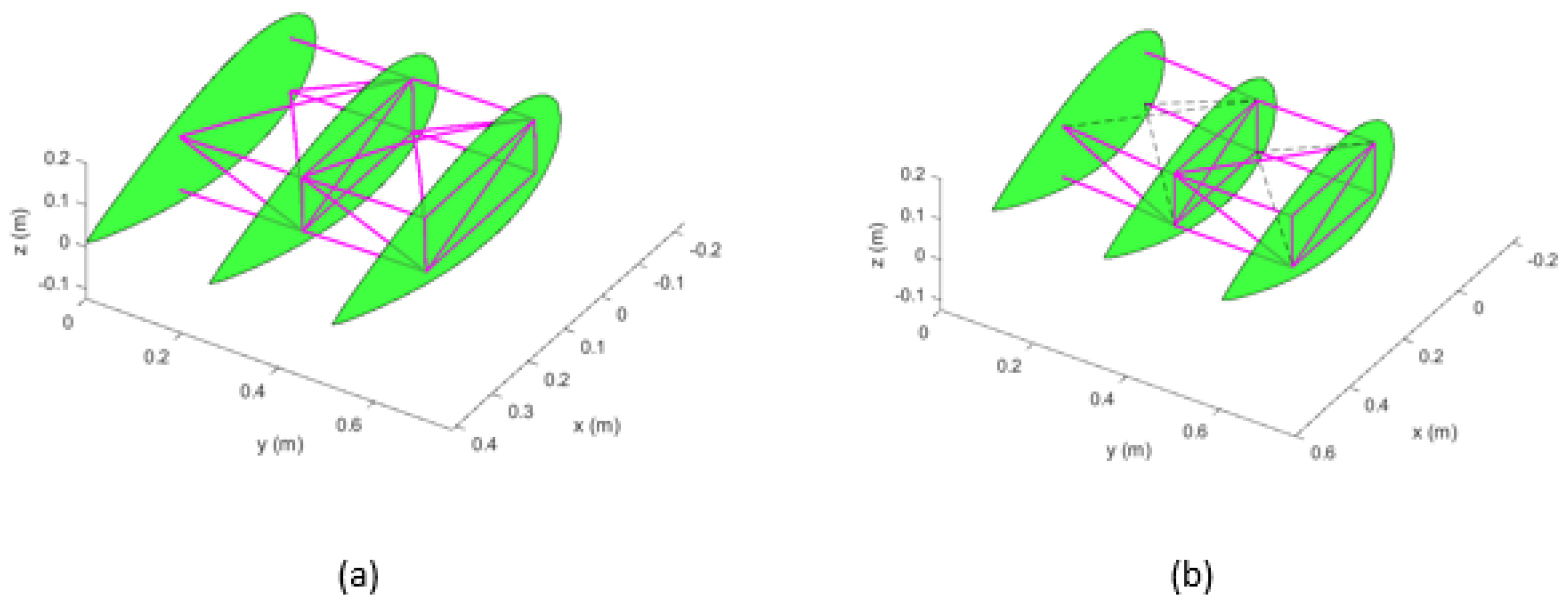
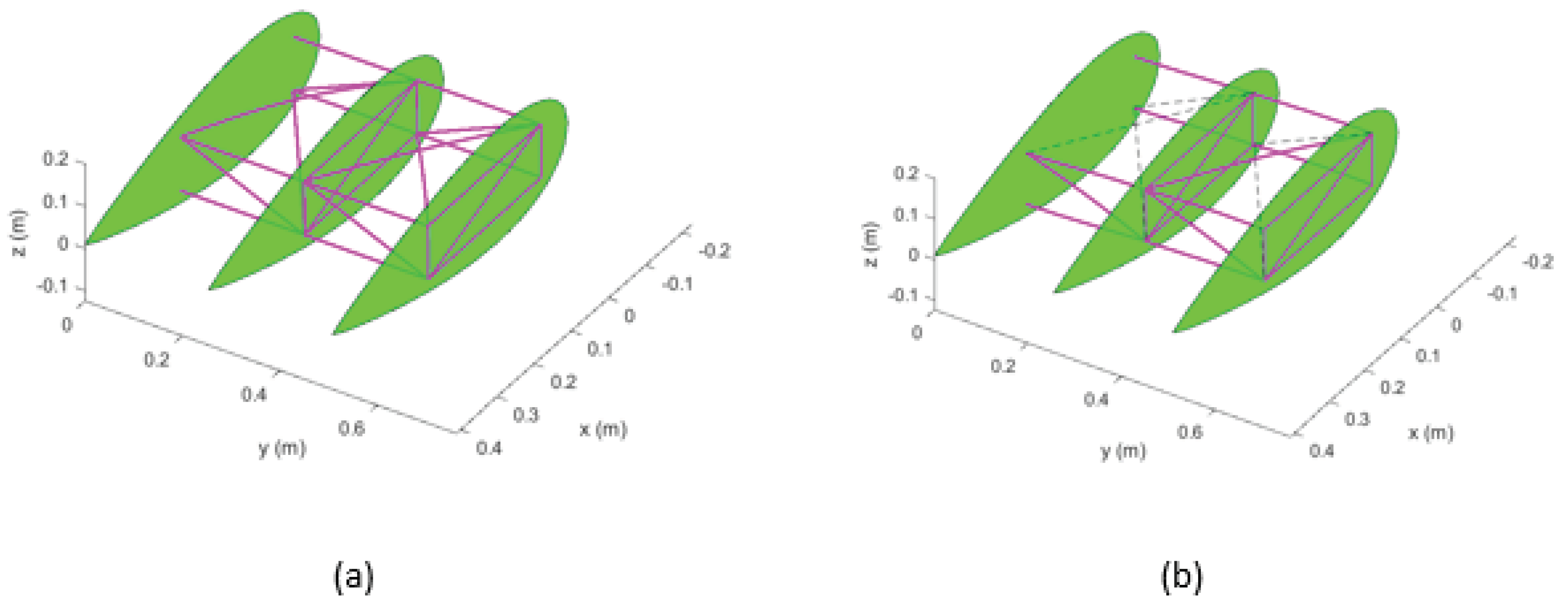
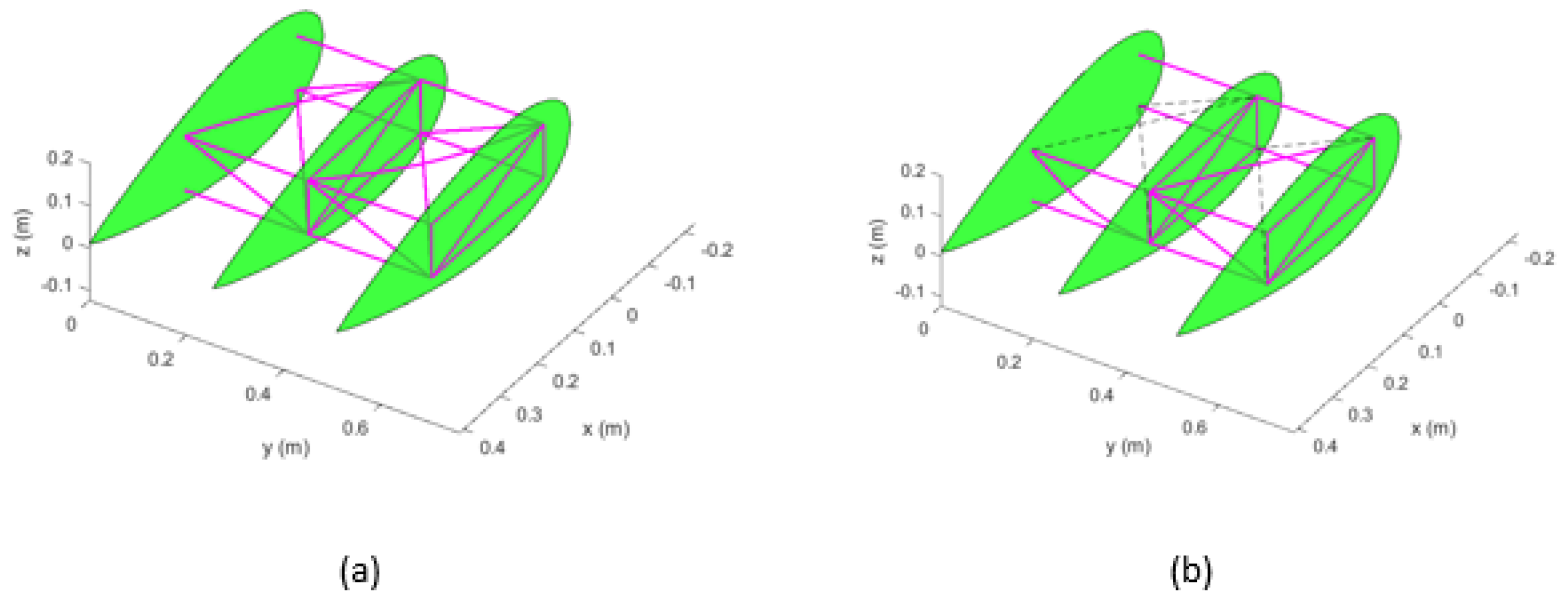
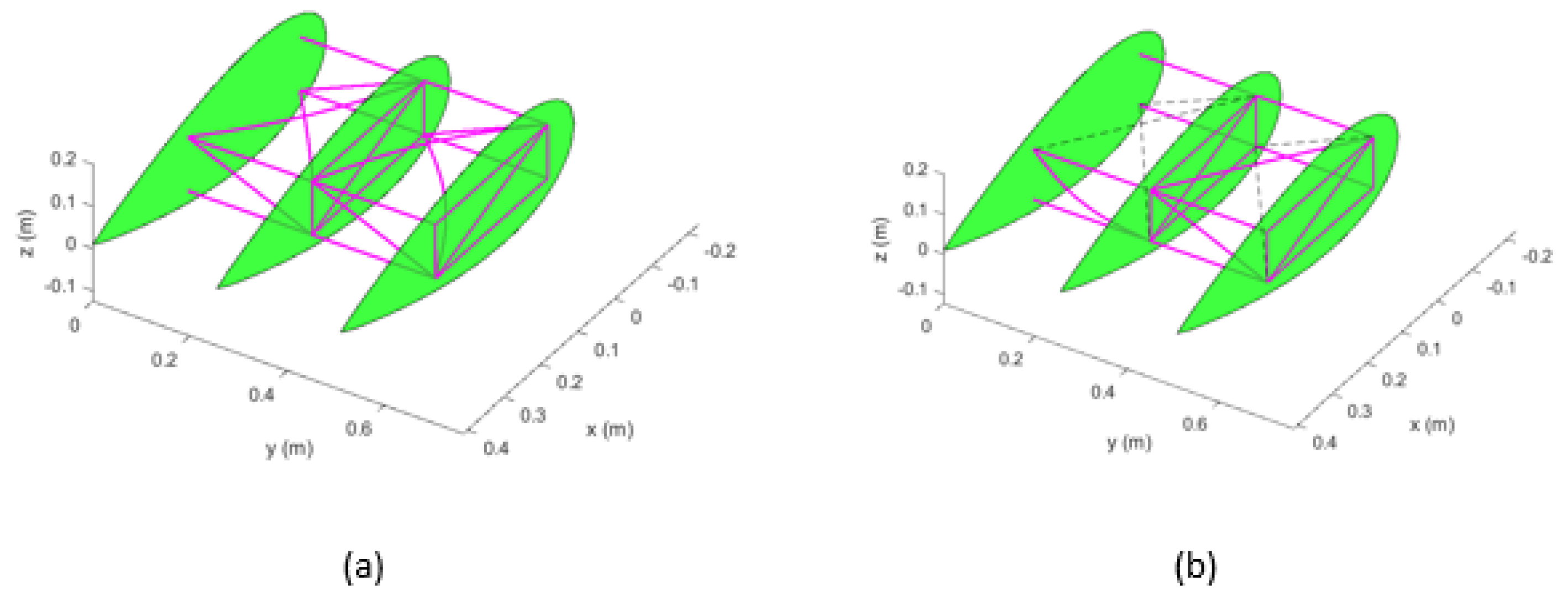
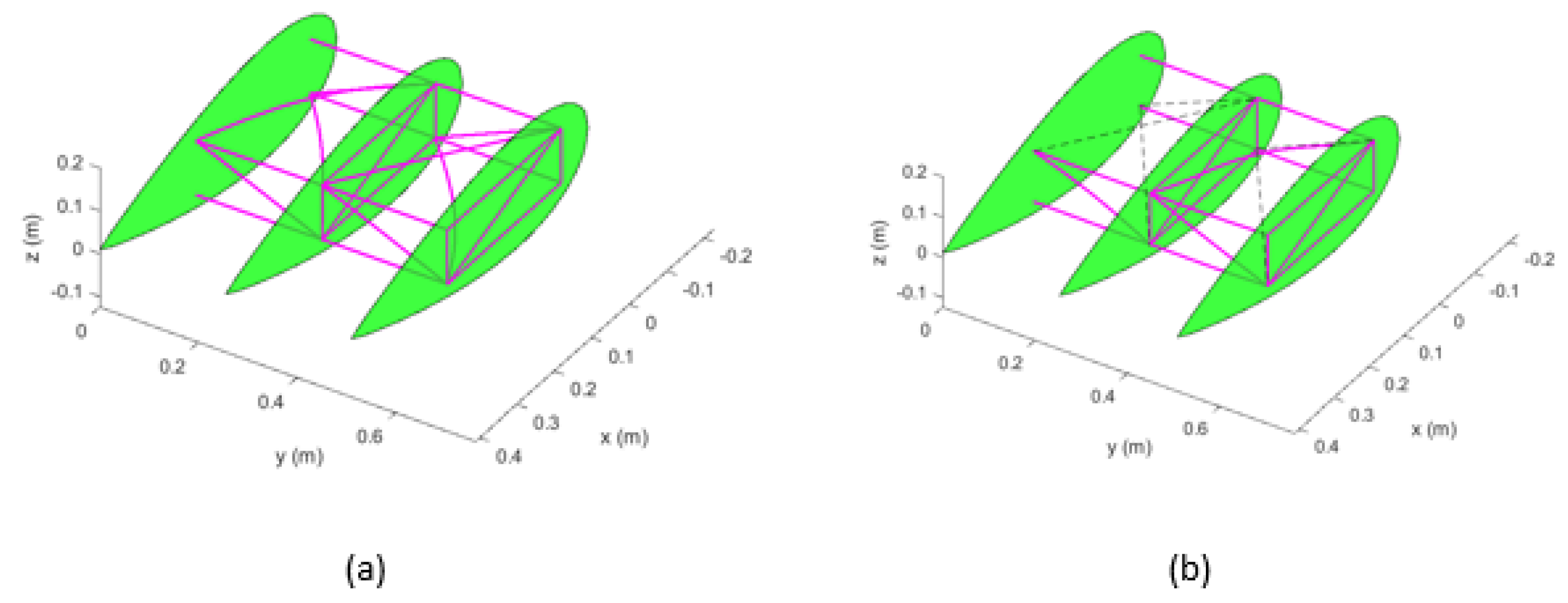
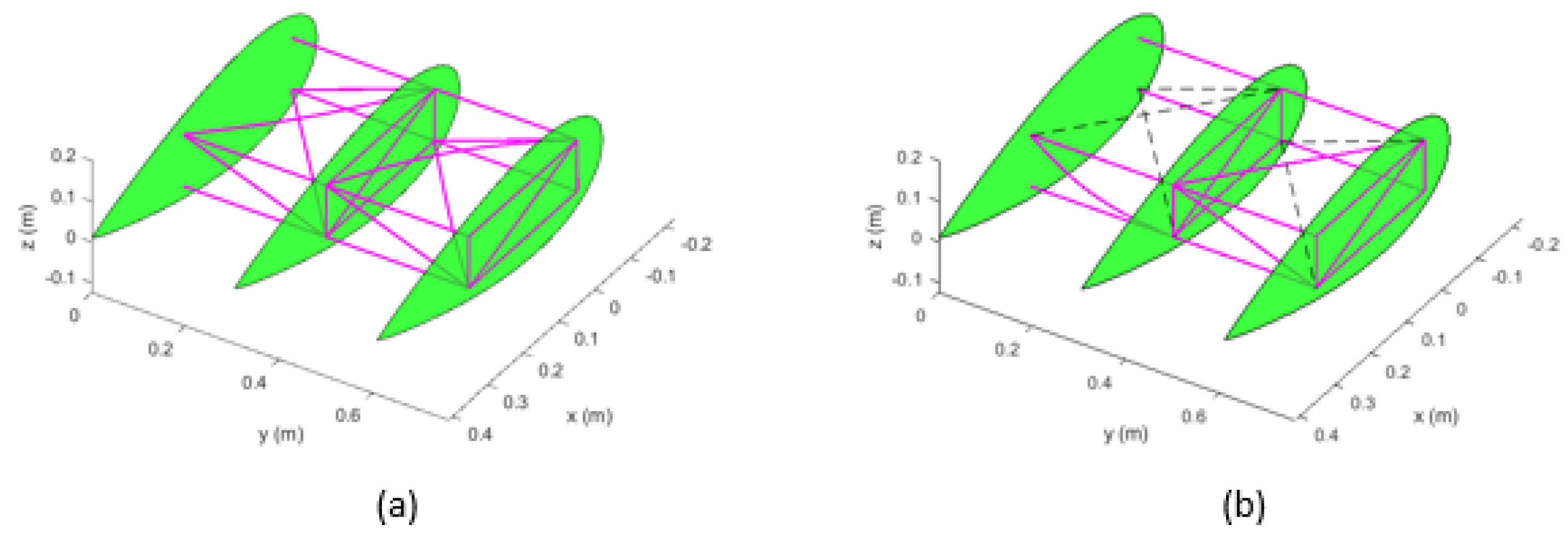
Table 10, and the corresponding mode shapes have been extracted. The first experiment, in essence, represents the fully intact system. For illustration purposes, only the first five mode shapes for experiment six, involving three ruptured active beams in the first module and two in the second one, are presented (Figure 5, Figure 6, Figure 7, Figure 8 and Figure 9). By comparing the fundamental frequency values of the defective and intact unmorphed configurations (see Table 8), it is found that all but the one for experiment two diminish. However, the next nine frequencies tend to exhibit an increase in their values.
It is noteworthy that in the presented simulations, the ruptured beam elements are entirely eliminated from the numerical FEM models. This practice leaves the defective system with a reduced and different mass–stiffness distribution. An increase in the natural frequencies of the defective system could be attributed to the fact that the mass and stiffness properties of the system are not affected to the same extent. In other words, the defective system undergoes more mass reduction compared to its stiffness reduction. In addition, the morphing design topology is statically indeterminate with more necessary elements. Therefore, the rupture of certain active beams may not drastically affect the overall system’s stiffness, while mass would be reduced. As can also be observed from Figure 5, Figure 6, Figure 7, Figure 8 and Figure 9, the corresponding mode shapes change noticeably, compared to their corresponding benchmark cases. Ruptured beams are represented by black dashed lines for illustration purposes (refer to Figure 5, Figure 6, Figure 7, Figure 8 and Figure 9). It is observed that in the case of the first mode, the damaged wing exhibits a more pronounced in-plane motion than the intact one. In the next four modes, however, the intact wing shows considerable flexural bending of the active beams compared to the corresponding mode shapes of the damaged system, see Figure 6, Figure 7, Figure 8 and Figure 9.
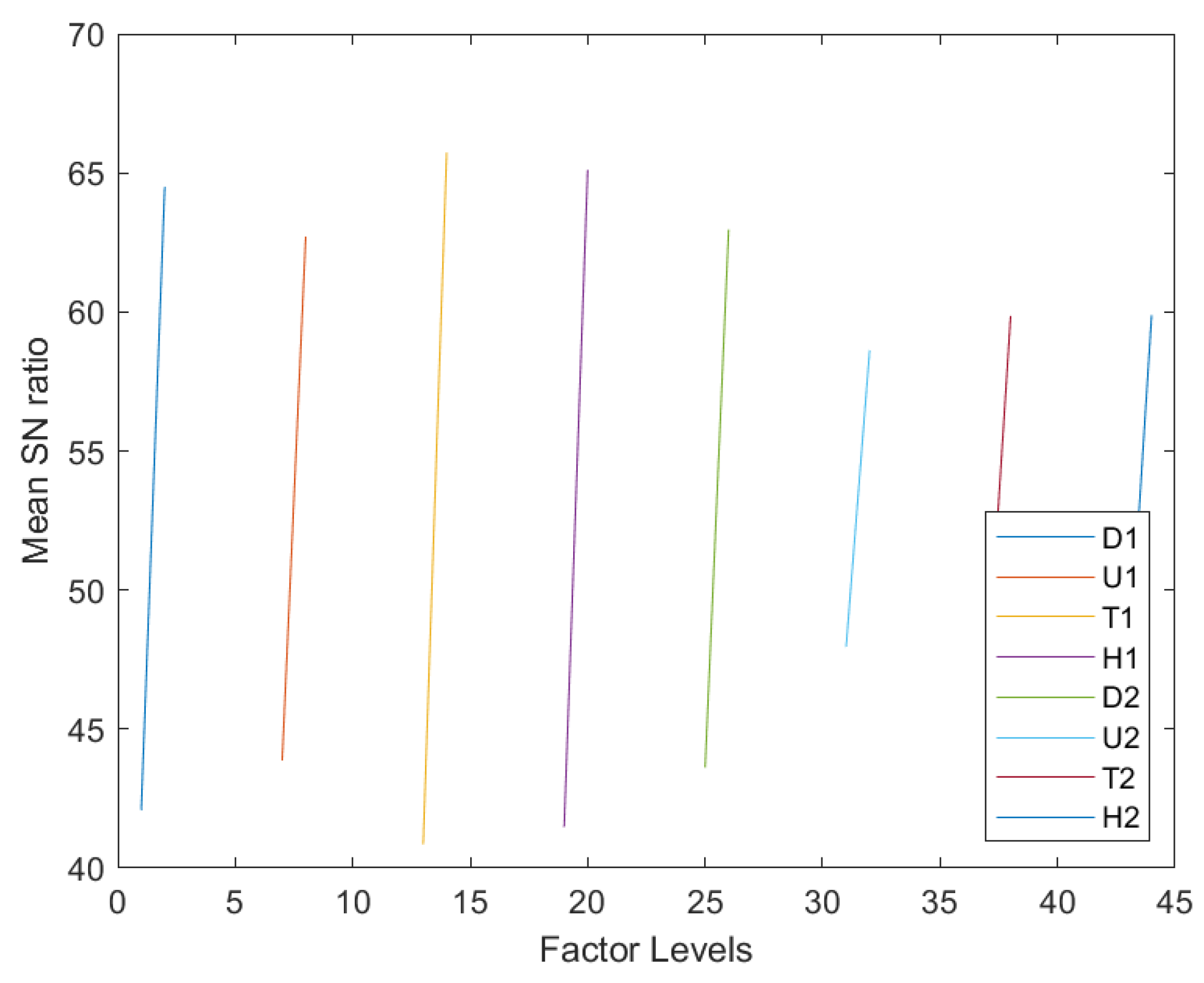
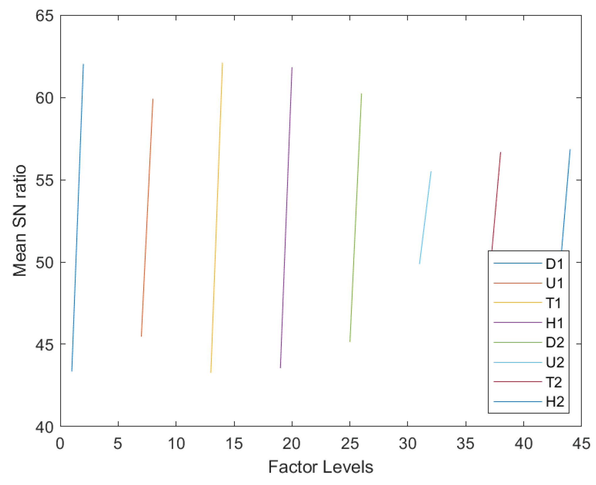
The signal-to-noise ratio (SN) [34,35,36] is computed for each factor’s level to investigate its effect on changing the natural frequencies of the morphing wing compared to the benchmark natural frequencies. Here, the maximum is a better SN ratio used to investigate the difference from the corresponding benchmark natural frequencies. Following the Taguchi technique, the mean SN ratios of the eight factors with two levels each, shifted along the abscissa for visual discernibility, given in Figure 10, for a representative case of the 4th natural frequency. By producing the SN ratios of the eight factors for all other natural frequencies, and comparing the difference between the factors’ highest and lowest mean SN, it is found that the hazards produced by the rupture of D1, T1, and H1 are the most critical governing factors in terms of transforming the vibration signature of the current re-configurable modular morphing wing.
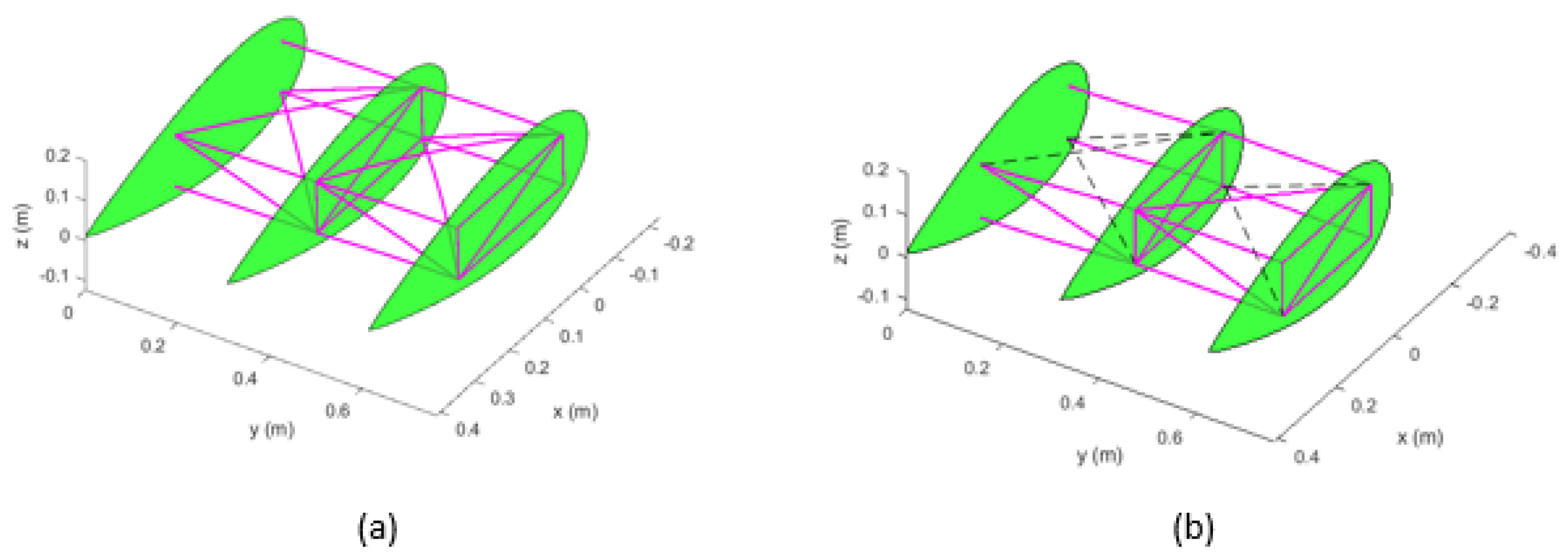
In what follows, the modal analysis is carried out for the intact morphed wing system (expanded span-wise by 20 % of the original wing length), with all the beams fully functional. The first ten natural frequencies are given in Table 11 below. Numerical simulations and experiments are then performed on the defective span-wise-morphed wing to study the hazard assessment. The resulting first ten natural frequencies, corresponding to the 12 experiments, are given in 
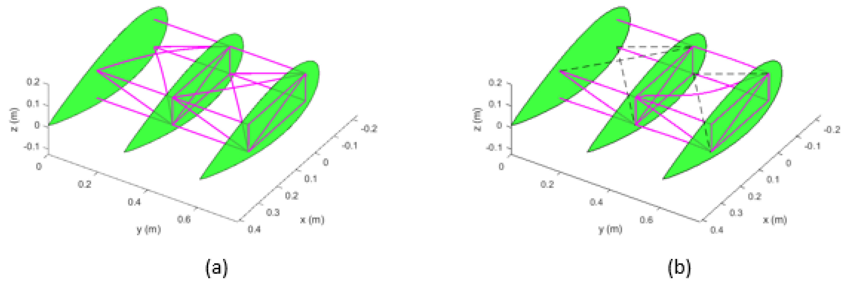
Table 12. Once again, only the first five mode shapes for experiment six, involving five ruptured active beams, are presented for illustration purposes (Figure 11, Figure 12, Figure 13, Figure 14 and Figure 15). As can be observed from the figures, the active beams in the defective wing do not exhibit very distinct flexural motions compared to the intact system. However, in the case of the second mode, the out-of-plane motion of the damaged wing is observed to be considerably higher than that of the intact configuration. By comparing the fundamental frequency values of the defective and intact morphed configurations (see 
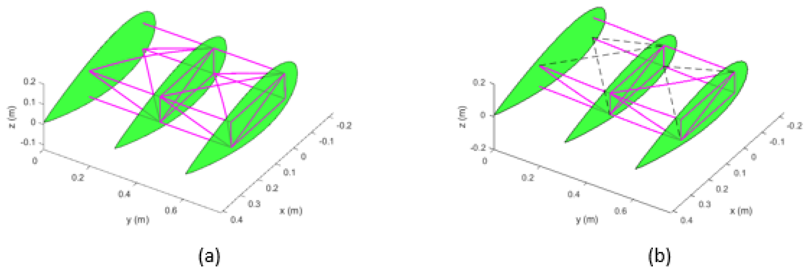
Table 11), one can observe that all but the one for experiment two reduce. Nevertheless, the next nine frequencies exhibit an increase, except the second frequency of experiment two. These trends can be explained using the same arguments as stated earlier in this paper about the unmorphed configurations. Similar to the previous case study, the signal-to-noise ratios (SN) of eight factors with two levels each are also computed here based on the corresponding natural frequencies of the fully intact morphed wing [34,35,36]. Mean SN curves corresponding to each factors’ level are depicted in Figure 16 for a representative case of the 4th natural frequency. By producing the SN ratios of the factors for all other frequencies, not presented here, it is observed that the hazard produced by the rupture of D1, T1 and H1 members are the most devastating factors.
Based on both case studies, these hazards (rupture of D1, T1, and H1) have been assigned the failure condition of ’hazardous’ due to the probable unexpected changes in the vibration signature. However, this could transform to the failure condition of ‘catastrophic’ in the presence of aerodynamic loads. Therefore, the aeroelastic analysis of such functional hazards is strongly recommended as the fluid–structure interaction could lead to the onset of flutter at lower speeds than that conceived during the preliminary design phase.

5. Conclusions

Compared to the fixed-shape counterparts, morphing wings bring prospective improvements in the lift-to-drag ratio, fuel saving, high performance at varying flight conditions, and enhancement of the flight envelope. However, due to the increased degrees-of-freedom and complexity of the structure, a potential failure of the component(s) could result in a drastic decline in the system’s performance or even a catastrophic failure condition. In the absence of airworthiness certification standards specifically outlined for the morphing wing, functional hazard assessment (FHA) becomes very challenging for such a system. In this paper, a re-configurable modular morphing wing design, developed in-house at the Toronto Metropolitan University (formerly Ryerson University), has been studied from the perspective of FHA. Hazards and their associated risks have been identified. A qualitative fault tree analysis (FTA) has been performed. It is shown that the identified hazards present ‘hazardous’ failure conditions from the perspective of the system’s vibration characteristics. However, the probability of such occurrence(s) is ‘extremely remote’, as required by the airworthiness certification. An exhaustive FEM-based modal analysis of systems involving various combinations of the identified hazards, in conjunction with the Taguchi method, revealed that the rupture of the first module’s active beams are the most critical components. On the basis of the presented simulation on the unmorphed and morphed configurations, it is concluded that the rupture of one of the downstream, toe, or head beam in module 1 (designated as D1, H1, and T1, respectively) could drastically affect the vibration signature of the studied morphing system. It is found that D1, H1 and T1 rank, respectively, the first, second and third (i.e., 90, 70, and 60 % of the time), in terms of their effect on the system’s natural frequencies. In the event of a failure, the higher natural frequencies are observed to shift towards lower ones, and some vibration modes disappear. This shift in the system’s natural frequencies could result in the onset of flutter at speeds lower than that conceived during the preliminary design phase. Therefore, a detailed quantitative FTA supplemented by aeroelastic analysis is highly recommended to ensure that a single failure does not cause a catastrophic failure condition, as mandated by the current airworthiness certification. In case of a potential catastrophic failure, safety measures must be implemented to make the design fail-safe.

Author Contributions

This paper presents the results of recent research conducted by the first author (F.M.) under the co-supervision of the second (S.M.H.) and third (H.A.) authors. All authors have read and agreed to the published version of the manuscript.

Funding

This research was partially supported by the Discovery Grant from the Natural Sciences and Engineering Research Council of Canada (NSERC), RGPIN-2017-06868.

Data Availability Statement

All data generated or analysed during this study are included within the article.

Acknowledgments

Support provided by the National Sciences and Engineering Research Council of Canada (NSERC), the Ontario Graduate Scholarship (OGS) program, the Queen Elizabeth II Graduate Scholarship in Science and Technology (QEII-GSST), and Toronto Metropolitan University (formerly Ryerson University), is highly acknowledged.

Conflicts of Interest

The authors declare that there are no conflicts of interest regarding the publication of this paper.

Abbreviations

The following abbreviations are used in this manuscript:
ARPAerospace Recommended Practice
DOFDegrees of Freedom
FEMFinite Element Methodology
FHAFault Hazard Assessment
FTAFault Tree Analysis
PSSAPreliminary System Safety Assessment
SNSignal-to-Noise Ratio
SSASystem Safety Assessment

References

  1. Arena, M.; Amoroso, F.; Pecora, R.; Ameduri, S. Electro-Actuation System Strategy for a Morphing Flap. Aerospace 2019, 6, 1. [Google Scholar] [CrossRef] [Green Version]
  2. International Civil Aviation Organization. Resolution A39-3: Consolidated Statement of Continuing ICAO Policies and Practices Related to Environmental Protection—Global Market-Based Measure (MBM) Scheme; Technical report; International Civil Aviation Organization: Montreal, QC, Canada, 2016. [Google Scholar]
  3. Li, L.; Bai, J.; Qu, F. Multipoint Aerodynamic Shape Optimization of a Truss-Braced-Wing Aircraft. J. Aircr. 2022, 59, 1179–1194. [Google Scholar] [CrossRef]
  4. Nae, C. Advanced Aerodynamic Technologies for Future Green Regional Aircraft. INCAS Bull. 2014, 6, 99–110. [Google Scholar]
  5. ICAO. ICAO: 37th Assembly Working Papers, A37-WP/402; Report of the Executive Committee on Agenda Item 17; Section on Climate Change; Technical report; ICAO: Montreal, QC, Canada, 2010. [Google Scholar]
  6. International Air Transport Association. IATA Technology Roadmap, 4th ed.; International Air Transport Association: Montreal, QC, Canada, 2013; pp. 1–78. [Google Scholar]
  7. Barbarino, S.; Bilgen, O.; Ajaj, R.M.; Friswell, M.I.; Inman, D.J. A Review of Morphing Aircraft. J. Intell. Syst. Struct. 2011, 22, 823–876. [Google Scholar] [CrossRef]
  8. Anderson, J.D. Introduction to Flight, 4th ed.; McGraw Hill Book Company: New York, NY, USA, 2000; pp. 1–78. [Google Scholar]
  9. Kress, R.W. Variable Sweep Wing Design. In Proceedings of the Aircraft Prototype and Technology Demonstrator Symposium, AIAA, Dayton, OH, USA, 23–24 March 1983; p. 1051. [Google Scholar]
  10. Chen, M.; Liu, J.; Skelton, R.E. Design and Control of Tensegrity Morphing Airfoils. Mech. Res. Commun. 2020, 103, 103480. [Google Scholar] [CrossRef]
  11. Ameduri, S.; Concilio, A. Morphing wings review: Aims, challenges, and current open issues of a technology. Proc. Imeche Part J. Mech. Eng. Sci. 2020. [Google Scholar] [CrossRef]
  12. Ajaj, R.; Parancheerivilakkathil, M.; Amoozgarb, M.; Friswellc, M.; Cantwell, W. Recent Developments in the Aeroelasticity of Morphing Aircraft. Prog. Aerosp. Sci. 2021, 120, 100682. [Google Scholar] [CrossRef]
  13. Dhara, A.; Ubhi, K.S.; Kumari, P.; Purewal, R.K.; Kumar, A. A Systematic Review of Morphing Wing in Aviation Industry. J. Emerg. Technol. Innov. Res. 2022, 9, 557–563. [Google Scholar]
  14. Previtali, F.; Arrieta, A.F.; Ermanni, P. Performance of a Three-Dimensional Morphing Wing and Comparison with a Conventional Wing. AIAA J. 2014, 52, 2101–2113. [Google Scholar] [CrossRef]
  15. Finistauri, A.D. Conceptual Design of a Modular Morphing Wing. Ph.D. Thesis, Department of Aerospace Engineering, Ryerson University, Toronto, ON, Canada, 2013. [Google Scholar]
  16. Joo, J.J.; Sanders, B.; Johnson, T.; Frecker, M.I. Optimal actuator location within a morphing wing scissor mechanism configuration. In Proceedings of the SPIE on Smart Structures and Materials: Modeling, Signal Processing, and Control, San Diego, CA, USA, 26 February–2 March 2006. [Google Scholar]
  17. Majji, M. Robust control of redundantly actuated dynamical systems. Master’s Thesis, Texas A&M University, College Station, TX, USA, 2006. [Google Scholar]
  18. Barrett, R. Active aeroelastic tailoring of an adaptive Flexspar stabilator. Smart Mater. Struct. 1996, 5, 723–730. [Google Scholar] [CrossRef]
  19. Hu, W.; Yang, Z.; Gu, Y. Aeroelastic Study for Folding Wing During the Morphing Process. J. Sound Vib. 2016, 365, 216–229. [Google Scholar] [CrossRef]
  20. Noviello, M.C.; Dimino, I.; Concilio, A.; Amoroso, F.; Pecora, R. Aeroelastic Assessments and Functional Hazard Analysis of a Regional Aircraft Equipped with Morphing Winglets. Aerospace 2019, 6, 104. [Google Scholar] [CrossRef] [Green Version]
  21. Klimaszewski, S.; Sajda, K.; Szawlowski, S. Small UAV SHM System Functional Hazard Analysis. J. KONBiN 2021, 51, 33–41. [Google Scholar] [CrossRef]
  22. Finistauri, A.D.; Xi, F.J.; Walsh, P. Discretization Method for the Development of a Modular Morphing Wing. J. Aircr. 2012, 49, 116–125. [Google Scholar] [CrossRef]
  23. Moosavian, A.; Xi, F.; Hashemi, S.M. Design and Motion Control of Fully Variable Morphing Wings. J. Aircr. 2013, 50, 253–264. [Google Scholar] [CrossRef]
  24. Mahmood, F.; Hashemi, S.M.; Alighanbari, H. Free Vibration Analysis of a Reconfigurable Modular Morphing Wing. Aerospace 2022, 9, 532. [Google Scholar] [CrossRef]
  25. Moosavian, A. Variable Geometry Wing-Box: Toward a Robotic Morphing Wing. Ph.D. Thesis, Ryerson University, Toronto, ON, Canada, 2014. [Google Scholar]
  26. Timoshenko, S. Vibration Problems in Engineering, 2nd ed.; D. Van Nostrand Company Inc.: New York, NY, USA, 1937. [Google Scholar]
  27. Zhang, Z.; Chen, F.; Zhang, Z.; Hua, H. Vibration Analysis of Non-uniform Timoshenko Beams Coupled with Flexible Attachments and Multiple Discontinuities. Int. J. Mech. Sci. 2014, 80, 131–143. [Google Scholar] [CrossRef]
  28. Mahmood, F. Transient Response of Varying Thickness Timoshenko Beam under Point Load. Master’s Thesis, Department of Mechanical Engineering, King Fahd University of Petroleum and Minerals, Dhahran, Saudi Arabia, 1999. [Google Scholar]
  29. Logan, D.L. A First Course in the Finite Element Method, 5th ed.; Cengage Learning: Stamford, CT, USA, 2012. [Google Scholar]
  30. Davis, R.; Henshell, R.; Warburton, G. A Timoshenko Beam Element. J. Sound Vib. 1972, 22, 475–487. [Google Scholar] [CrossRef]
  31. Guidelines and Methods for Conducting the Safety Assessment Process on Civil Airborne Systems and Equipment: ARP4761; Technical report; US SAE International: Warrendale, PA, USA, 1996.
  32. U.S. Department of Transportation, Federal Aviation Administration. Advisory Circular: AC No:25.1309-1B; Technical report; U.S. Department of Transportation, Federal Aviation Administration: Washington, DC, USA, 2002.
  33. Code of Federal Regulations. Available online: https://www.ecfr.gov/current/title-14/chapter-I/subchapter-C/part-25/subpart-F/subject-group-ECFR9f24bf451b0d2b1/section-25.1309 (accessed on 2 February 2023).
  34. Mistree, F.; Lautenschlager, U.; Erikstad, S.O.; Allen, J.K. Simulation Reduction Using the Taguchi Method; Technical report; NASA Report 4542; Systems Design Laboratory Department of Mechanical Engineering University of Houston: Houston, TX, USA, 1993. [Google Scholar]
  35. Tambolkar, P.; Ponkshe, A.; Mulay, V.; Bewoor, A. Use of Taguchi DOE for CFD Simulation to maximize the Reusability of Working Fluids of Centrifugal Filter. Procedia Manuf. 2020, 46, 608–614. [Google Scholar] [CrossRef]
  36. Krishnaiah, K.; Shahabudeen, P. Applied Design of Experiments and Taguchi Methods; PHI Learing Pvt Ltd.: New Delhi, India, 2012. [Google Scholar]
Figure 1. Configuration of structural element connections in the morphing wing; (a) the actual prototype, and (b) CAD model.
Aerospace 10 00300 g001
Figure 2. Mechanism design of the re-configurable morphing wing [23].
Aerospace 10 00300 g002
Figure 3. Qualitative fault tree for the active beam rupture.
Aerospace 10 00300 g003
Figure 4. Unmorphed wing in original (un-deformed) configuration.
Aerospace 10 00300 g004
Figure 5. First mode shape for the system in the unmorphed configuration, (a) intact, and (b) ruptured beams (experiment six).
Aerospace 10 00300 g005
Figure 6. Second mode shape for the system in the unmorphed configuration, (a) intact and (b) ruptured beams (experiment six).
Aerospace 10 00300 g006
Figure 7. Third mode shape for the system in the unmorphed configuration, (a) intact and (b) ruptured beams (experiment six).
Aerospace 10 00300 g007
Figure 8. Fourth mode shape for the system in the unmorphed configuration, (a) intact and (b) ruptured beams (experiment six).
Aerospace 10 00300 g008
Figure 9. Fifth mode shape for the system in the unmorphed configuration, (a) intact and (b) ruptured beams (experiment six).
Aerospace 10 00300 g009
Figure 10. SN ratio for the FHA of the unmorphed wing.
Aerospace 10 00300 g010
Figure 11. First mode shape for the system in a 20 % span-wise expansion configuration, (a) intact and (b) ruptured beams (experiment six).
Aerospace 10 00300 g011
Figure 12. Second mode shape for the system in a 20 % span-wise expansion configuration, (a) intact and (b) ruptured beams (experiment six).
Aerospace 10 00300 g012
Figure 13. Third mode shape for the system in a 20 % span-wise expansion configuration, (a) intact and (b) ruptured beams (experiment six).
Aerospace 10 00300 g013
Figure 14. Fourth mode shape for the system in a 20 % span-wise expansion configuration, (a) intact and (b) ruptured beams (experiment six).
Aerospace 10 00300 g014
Figure 15. Fifth mode shape for the system in a 20 % span-wise expansion configuration, (a) intact and (b) ruptured beams (experiment six).
Aerospace 10 00300 g015
Figure 16. SN ratio for the parametric design analysis.
Aerospace 10 00300 g016
Table 1. Benefits and challenges of wing morphing [15].
Morphing TypePerformance EffectsBenefitCost
SpanAspect Ratio, Wing loadingShorter span maneuverabilityIncrease in wing root moment
SweepDrag-divergence, Mach numberManeuvers, high-speed flightLower lift coefficient, higher weight
ChordAspect Ratio, Wing loadingimprovement in lift-to-drag ratioIncrease in induced drag
DihedralLateral stabilityIncrease in roll (lateral) stabilityDecrease in maneuverability
TwistLift, DragAerodynamic force controlLower wing torsional rigidity
Table 2. Classifications of failure conditions [32].
Failure ConditionDefinition
No Safety EffectNo effect on the operational capability of the aircraft (A/C), no discomfort to passengers and crew, no increase in workload on the crew.
MinorSlight reduction in safety margins or functional capabilities, slight increase in workload on the crew, or some physical discomfort to passengers.
MajorSignificant reduction in safety margins or functional capabilities, significant increase in workload on the flight crew, or some injuries to passengers or flight attendants.
HazardousLarge reduction in safety margins or functional capabilities, excessive and unmanageable workload on the flight crew, or fatal injuries to some passengers, but not to the flight crew.
CatastrophicMultiple fatalities with the loss of the aircraft.
Table 3. Qualitative probability classification [32].
Probability ClassificationQuantitative Probability (P) Per Flight HourRationale
Probable P > 10 5 Anticipated to occur one or more times during the entire operational life of each aeroplane of a given type.
Remote 10 7 < P < 10 5 Not anticipated to occur to each aeroplane of a given type during its entire operational life, but which may occur several times during the total operational life of a number of aeroplanes of a given type.
Extremely Remote 10 9 < P < 10 7 Not anticipated to occur to each aeroplane during its entire operational life, but which may occur a few times during the total operational life of all aeroplanes of a given type.
Extremely Improbable P < 10 9 Not anticipated to occur during the total operational life of all aeroplanes of a given type.
Table 4. Fault Hazard Assessment of the Modular Morphing Wing.
No.FunctionPhaseHazardFailure ConditionImpactProbability RequirementDetection
1Load ControlAllBeam RuptureHazardousWing and A/C Structural DamageExtremely RemoteAdverse Vibration
2Load ControlAllController FailureMajorUncontrolled PerformanceRemoteWarning Signal
3Load ControlAllBeam JamMajorUncontrolled PerformanceRemoteWarning Signal
Table 5. Material properties of structural members (excluding ribs).
MaterialDensityModulus of ElasticityPoisson RatioShear Modulus
kg/m3Pa Pa
Low-Carbon Steel7750.41.8616 × 10 11 0.37.16 × 10 10
Table 6. Designation of beams identified as hazards for FHA.
DesignationD1U1T1H1D2U2T2H2
Beam LocationDownstream Module 1Upstream Module 1Toe Module 1Head Module 1Downstream Module 2Upstream Module 2Toe Module 2Head Module 2
Table 7. Two levels of beam functionality.
Level IdentifierBeam Status
1Fully Functional
2Ruptured
Table 8. Benchmark case (unmorphed) natural frequencies, ω (rad/s) of the wing.
Mode12345678910
1528.91915.71927.21932.41937.71967.61974.51975.42462.62862.4
Table 9. Taguchi orthogonal array for simulations.
ExperimentFactor Levels
D1U1T1H1D2U2T2H2
111111111
211111222
311222111
412122122
512212212
612221221
721221122
821212221
921122212
1022211112
1122121211
1222112121
Table 10. Taguchi-based natural frequencies of the defective unmorphed wing.
ExperimentNatural  Frequencies ω (rad/s)
12345678910
11528.91915.71927.21932.41937.71967.61974.51975.42462.62862.4
21896.41926.31932.41974.91977.72727.23600.03749.93856.23909.2
31012.12521.93137.43420.93771.73811.83919.73982.74532.54853.8
41521.82502.43050.63148.33813.23859.15989.16938.07206.67247.0
51241.12938.23043.03479.53593.23991.94412.64670.34872.17206.8
6899.42341.53776.33945.44520.04669.36541.07205.37234.87242.7
7943.32602.92831.87002.37205.07234.97242.87247.07643.07646.1
81242.62942.93045.33519.34234.74713.84742.67206.77247.07301.8
91242.22882.63016.43548.84214.24705.14730.97206.77247.07298.9
10840.72966.63064.23331.34567.64579.17007.27232.27496.07523.2
11830.42879.22998.23068.43218.23535.54631.34665.96239.57232.2
121090.72981.62992.43012.93068.83072.33334.14603.16592.87603.8
Table 11. Natural frequencies, ω (rad/s) of the morphed wing with a span-wise expansion of 20 % without damage.
Mode12345678910
1135.41553.91562.81567.31573.641595.71601.21601.91871.22106.7
Table 12. Taguchi-based natural frequencies of morphed wing with a span-wise expansion of 20 % for the functional hazard assessment.
ExperimentNatural Frequencies ω (rad/s)
12345678910
1135.41553.91562.91567.31573.61595.71601.21602.01871.22106.7
1253.21532.01565.51597.11601.51962.02504.12582.92638.22662.1
645.81915.62538.52550.12596.82667.32735.72804.43680.93804.8
1013.61816.72469.52505.32637.02644.64432.94567.04632.64644.2
841.32322.92457.52537.62600.42896.43239.43724.53760.14632.6
574.11696.32608.82690.73666.43711.84378.84632.24639.04641.6
615.61868.41868.74547.74632.24639.04641.64644.24811.34812.1
842.22353.82466.22764.33117.83729.73767.74632.64644.24693.8
842.02279.62436.52804.93116.43727.23766.64632.64644.24691.7
540.22393.72491.72689.23702.23711.04557.04638.34775.54812.0
535.12320.02439.02491.42610.82867.83729.43785.44309.14638.3
707.42413.92429.42455.32491.12494.12689.63634.54577.25090.3
Disclaimer/Publisher’s Note: The statements, opinions and data contained in all publications are solely those of the individual author(s) and contributor(s) and not of MDPI and/or the editor(s). MDPI and/or the editor(s) disclaim responsibility for any injury to people or property resulting from any ideas, methods, instructions or products referred to in the content.

