Article

Design of Large-Scale Space Lattice Structure with Near-Zero Thermal Expansion Metamaterials

1
School of Aeronautics and Astronautics, University of Chinese Academy of Sciences, Beijing 100049, China
2
Key Laboratory of Space Utilization, Technology and Engineering Center for Space Utilization, Chinese Academy of Sciences, Beijing 100094, China
*
Author to whom correspondence should be addressed.
Aerospace 2023, 10(3), 294; https://doi.org/10.3390/aerospace10030294
Submission received: 16 January 2023 / Revised: 8 March 2023 / Accepted: 11 March 2023 / Published: 16 March 2023
(This article belongs to the Special Issue Advanced Spacecraft/Satellite Technologies)

Abstract

:
Thermal expansion is inevitable for space structures under the alternating temperature of outer space around the earth. This may lead to the thermal stress and deformation due to the mismatch of the coefficient of thermal expansion. Near-zero thermal expansion (Near-ZTE) is a vitally essential demand for large-scale space telescopes or antennas to preserve their spatial precision and resolution. Recently, mechanical metamaterials with superior and tailorable properties have attracted significant interest with regard to developing negative materials or ultra-property materials. In this paper, the near-ZTE space structure architected by a dual-hourglass bi-material lattice is achieved by the structural optimization method with the gradient-based algorithm. First, an hourglass lattice with adjustable structural parameters is optimized to seek the design of effective negative thermal expansion (NTE) in the thickness direction. Then, two building blocks with both NTE and legacy positive thermal expansion (PTE) are combined as a dual-layered lattice to obtain the near-ZTE. Finally, a structure with near-ZTE of about ~10−9 m/(m·K) is obtained. Furthermore, the various lattice configurations, such as the hexagonal pyramid and triangle pyramid, are investigated in detail. Finally, the natural frequencies of two near-ZTE lattices are calculated by the modal analysis method, and the stiffness is discussed for the optimal solution of space applications. This work demonstrates that the near-ZTE structure can be achieved by utilizing the negative metamaterial and structural optimization method. It provides a novel solution to design the large-scale space structures with the near-zero thermal induced deformation, and may be constructed and assembled by the on-orbit fabrication technology.

1. Introduction

The heat absorption from solar radiation and heat dissipation from cosmic background radiation supply an alternative temperature field for spacecraft operating in outer space around the Earth [1,2,3,4]. Large-scale space structures such as space telescopes and reflector antennas [5,6] are typically of more sensitive to the mismatch of coefficient thermal expansion (CTE). To deal with the effects, the thermomechanical metamaterials with near-ZTE properties have attracted favorable interest in terms of stabilizing the thermal deformation of the space structures.
There are various methods of designing metamaterials with programmable CTE, such as bending-dominated [7,8,9,10,11], stretching-dominated [12,13,14,15,16], and representative topology optimized types [17,18,19]. Timoshenko [7] found a general theory for the bending of a bi-metal strip subjected to a uniform heating and developed a thermostat utilizing this mechanism. And utilizing this method, Lakes et al. [8] designed a lattice structure with programmable CTE properties. Wu et al. [9] designed a metamaterial with an isotropic and tunable negative thermal expansion on any scale. Yu et al. [10] composed a tunable 2D homogeneous thermal expansion metamaterial underlying the conversion of thermal-induced deflection of bilayer beams. Jefferson et al. [11], based on the internal cell bending deformation, designed a bi-material nested planar hexagonal lattice with the effect of zero thermal expansion.
According to the sketching-dominated deformation and rotation, Steeves et al. [20,21] designed a family of triangular planar lattices which have low thermal expansion and high structural stiffness, both theoretically and experimentally. Hopkins et al. [22] designed a re-entrant polygon microstructure with superior thermal expansion properties. Parsons et al. [23] developed a special lattice with NTE attributes though a negative Poisson ratio and bi-material design. Inspired by the crystallography, Wei et al. [12,24,25,26] constructed two classes of planar metamaterials with the isotropic CTEs and verified the theorical design through experimentation. Wang et al. [13] devised a programmable CTE structure constituting a bi-material pyramid unit cell through the matrix transformation method. Peng [14] et al. devised a class of 3D metamaterial by using an exclusive geometrical methodology. Xu et al. [15] developed a bi-material hourglass-lattice metastructure and reached ZTE performance in thickness direction by stacking the NTE and PTE layers. He et al. [16] designed a cellular structure for coupling the tailorable coefficient of thermal expansion and tunable Poisson’s ratio properties.
Combining the topology optimization method and additive manufacturing technology, Takezawa et al. [17,27] developed a design methodology for porous composites with tunable thermal expansion. Hirtoa et al. [18] used a topology optimization method to design a planar periodic metastructure with NTE attributes. Yang et al. [19] proposed a novel dual-constituent lattice sandwich panel with optimal in-plane thermal expansion and stiffness properties.
At present, there are a few methods which have been developed for optimization problems. The gradient descent method [28,29] considers the negative gradient as a searching direction because of the fastest descent being at the current position. It has the advantages of being the most widely used and simplest realization, but the convergence pace will be noticeably slow when approaching the minimum. Newton’s method [30,31] uses the Taylor series approximation to obtain the solution of the functions. Owing to the second-order convergence, the method has faster pace but with high sophistication to calculate the Hessian matrix. Subsequently, the conjugate gradient method [32,33] combined the advantages of fast convergence rate and low calculation cost, but involves a more sophisticated theory derivation above all.
In the previous research, scholars have demonstrated that the engineered lattice configuration could lead to extraordinary thermal and mechanical behaviors. However, the investigations on the tunable CTE design field are mostly under a line array configuration, which is not appropriate for structures such as a space telescope. Moreover, the scales of legacy metastructures are not suitable for the utilization of large structures on orbit fabrication. This paper devised a novel design method for a bi-material hourglass lattice in circular array conditions. It enables the carrying out of near-ZTE performance combining the stretch-dominated concept and structural parameter optimization. A general design method of a ZTE metastructure is proposed to adapt to a varisized in-space construction index, and to establish a preliminary guideline of a low-cost large-scale design method. Firstly, the theoretical analysis of stretching-dominated type hourglass-lattice and structural optimization with the gradient-based algorithm is devised. Secondly, the conceptual design of the lattice structure and thermomechanical finite element method (FEM) is introduced. Next, to demonstrate the feasibility of the hourglass lattice design and adapt the construction technique, the ZTE attributes with regard to the condition of diverse types of unit cells are investigated. Furthermore, the modal analysis is performed to determine the rationality of the natural frequency under the unconstrained state in space. Finally, the discussion and conclusions are provided.
The novelty of this paper is mainly threefold: (1) The bi-material dual-layer hourglass metamaterial design of hexagonal type and triangular type are proposed with the near-ZTE capacity by a structural optimization scheme; (2) Metastructures with different circular arrays of lattices are established and constructed, with an overall ZTE performance; (3) The natural frequency behaviors of the circular array structures are analyzed, and an optimal cell array layout is obtained.
The structure of the paper is organized as follows: first, the construction of bi-material hourglass lattice metamaterials is introduced. Second, the topological optimization procedure is discussed. The numerical investigation of NTE lattices and ZTE lattices are then described. The configurations of both hexagonal and triangular types are discussed. Finally, the modal analysis and stiffness behaviors are discussed in detail.

2. Bi-Material Hourglass Lattice Metamaterials

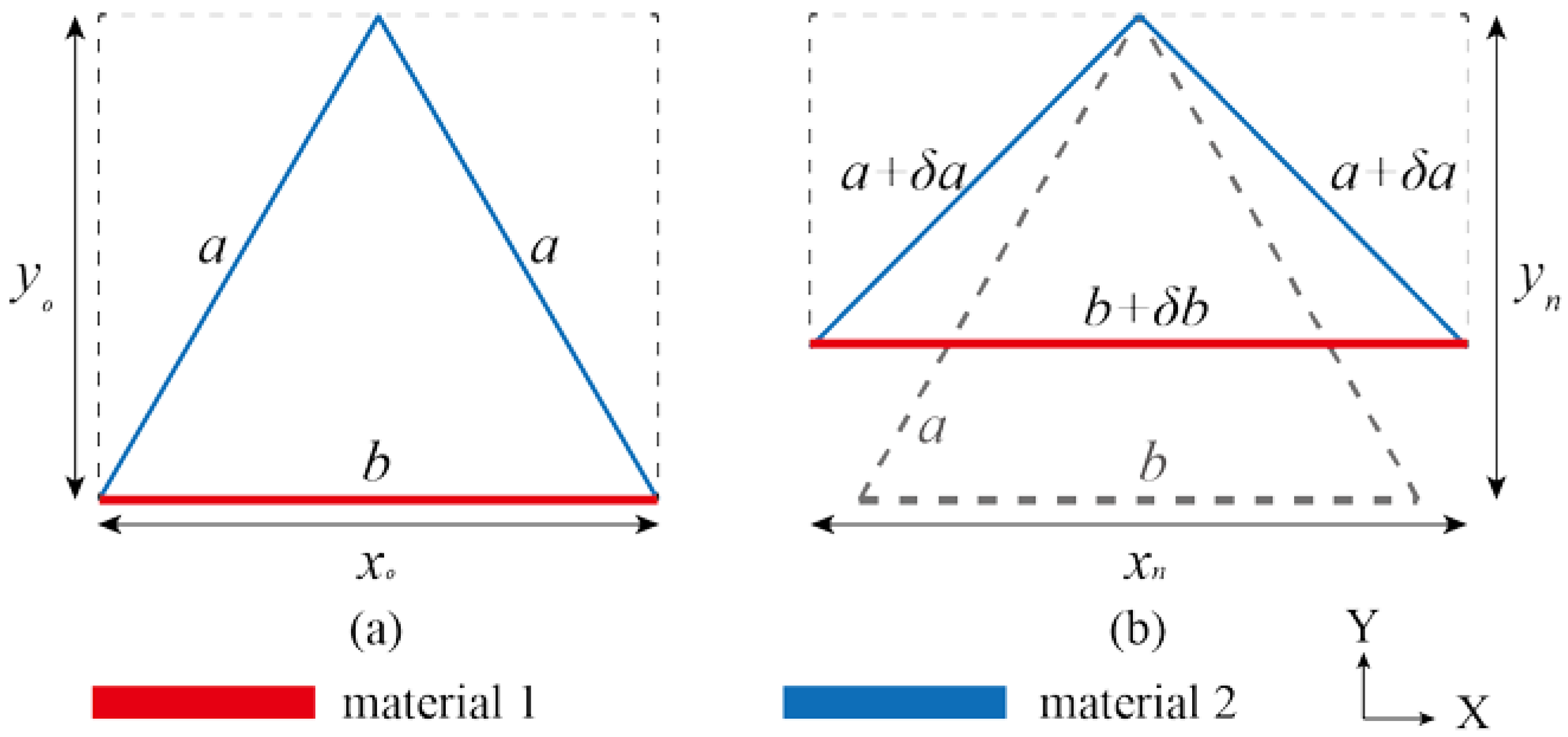
2.1. Theoretical Analysis for Triangular Cell

It is known that the triangle configuration is the simplest hinged structure that is free to deform upon temperature change [34,35]. An isosceles triangle structure is considered here. Two equal-length beams are constituted with one material and the base beam is constituted with another material. The shape before and after heat transformation are shown in Figure 1.
Assume that the CTE of two materials are α1 and α2, respectively. The origin length of the hypotenuse is a, and that of the brace is b. According to the Pythagorean theorem and the thermal expansivity of the triangle configuration, we can get that,
α x = α 2
y 0 2 = a 2 b 2 2
( y 0 + δ y ) 2 = ( a + δ a ) 2 b + δ b 2 2
And in general:
α y = δ y y 0 · Δ T
Thus, the effective CTE in y-direction is,
α y = 4 a 2 α 1 b 2 α 2 4 a 2 b 2
In the real alternative thermal condition, the overall CTE in the y-direction is related to the section area, the second moment of area, the beam length, etc. Thus, the discretized mesh of each cross-section of the beam in FEM is uniform. The local stiffness matrix of a beam element [36] in the 3D coordinate system is expressed as Equation (6):
k e ( 12 × 12 ) = E A L 0 0 0 0 0 E A L 0 0 0 0 0 0 12 E I z L 3 0 0 0 6 E I z L 2 0 12 E I z L 3 0 0 0 6 E I z L 2 0 0 12 E I y L 3 0 6 E I y L 2 0 0 0 12 E I y L 3 0 6 E I y L 2 0 0 0 0 G J L 0 0 0 0 0 G J L 0 0 0 0 6 E I y L 2 0 4 E I y L 0 0 0 6 E I y L 2 0 2 E I y L 0 0 6 E I z L 2 0 0 0 4 E I z L 0 6 E I z L 2 0 0 0 2 E I z L E A L 0 0 0 0 0 E A L 0 0 0 0 0 0 12 E I z L 3 0 0 0 6 E I z L 2 0 12 E I z L 3 0 0 0 6 E I z L 2 0 0 12 E I y L 3 0 6 E I y L 2 0 0 0 12 E I y L 3 0 6 E I y L 2 0 0 0 0 G J L 0 0 0 0 0 G J L 0 0 0 0 6 E I y L 2 0 2 E I y L 0 0 0 6 E I y L 2 0 4 E I y L 0 0 6 E I z L 2 0 0 0 2 E I z L 0 6 E I z L 2 0 0 0 4 E I z L
The thermal load of the element is
f e ( 12 × 1 ) = α · Δ T · E · A · B T · L
where the thermal gradient vector is:
B ( 1 × 12 ) = 1 0 0 0 0 0 1 0 0 0 0 0 / L
In general, the mechanical variables are transformed from the local coordinate system to the global one,
  k e ¯ ( 12 × 12 ) = T T k e T   f e ¯ ( 12 × 1 ) = T T f e
The transformation matrix of 2D element T is given by:
T ( 12 × 12 ) = λ ( 3 × 3 ) 0 ( 3 × 3 ) 0 ( 3 × 3 ) 0 ( 3 × 3 ) 0 ( 3 × 3 ) λ ( 3 × 3 ) 0 ( 3 × 3 ) 0 ( 3 × 3 ) 0 ( 3 × 3 ) 0 ( 3 × 3 ) λ ( 3 × 3 ) 0 ( 3 × 3 ) 0 ( 3 × 3 ) 0 ( 3 × 3 ) 0 ( 3 × 3 ) λ ( 3 × 3 )
where the coordinate projection matrix of 2D element [λ] is given by:
λ ( 3 × 3 ) = cos ( x , x ¯ ) cos ( x , y ¯ ) cos ( x , z ¯ ) cos ( y , x ¯ ) cos ( y , y ¯ ) cos ( y , z ¯ ) cos ( z , x ¯ ) cos ( z , y ¯ ) cos ( z , z ¯ )
As shown in the above equations, the thermal deformation is related to the section area, profile type, beam length, etc. It was proven that the above variables are influencing the CTE though this theoretical analysis. Thus, considering these parameters’ effects, the stretching-dominated unit cells or meta-units with a programmable CTE are proposed.

2.2. Bi-Material Design of Metametarials

Two basic configurations are proposed to seek the ZTE design. They are the hexagonal hourglass type and the triangle hourglass type. The schematic illustration of two types of single layer hourglass unit cells is shown in Figure 2. It is composed of two materials. The top and bottom braces are chosen to be nylon, and the hypotenuses are CFRP-nylon in this analysis [15]. The mechanical and thermal properties of the two different materials are listed in Table 1. Under the background of in-space fabrication, the length of braces is set as L = 6 m, and that of the hypotenuses vary with the height.
The materials listed in Table 1 are only used for demonstration purposes. This design optimization methodology is also suitable to other material pairs if their CTEs have a high contrast and are 3D printable by the additive manufacturing technology, such as with thermoplastics [37].
In this paper, this hourglass shape is set as the baseline in seeking the configuration of NTE. According to the effective medium theory [38], the ZTE or near-ZTE goal can be achieved by combining both the PTE and NTE lattices. The PTE hourglass lattice is easily obtained by using the same configuration of NTE lattice with a single material. Then, stacking both NTE and PTE lattices in the thickness direction will reach the goal, as depicted in Figure 3. Each layer height of the dual-hourglass lattice is considered as H1 and H2, respectively.
The large-scale space lattice structure is constructed by the way of arranging the dual-layer unit cells into a circular array. The array number N represents the number of circular layers of the unit cells that are around the centered unit cell (N = 0). The circular array method is shown schematically in Figure 4. This type of configuration is widely used in the design of space telescopes and antennas, such as the James Webb space telescope [39]. The lattice structures in various array conditions have all satisfied the rule of the circumferentially dense accumulation. The beams are connected to a whole through the coincident nodes from each other. Two types of circular array are shown in Figure 5. All the beams in the dual construction have a tunable section radius, which is the sensitive parameter for optimizing the ZTE design.

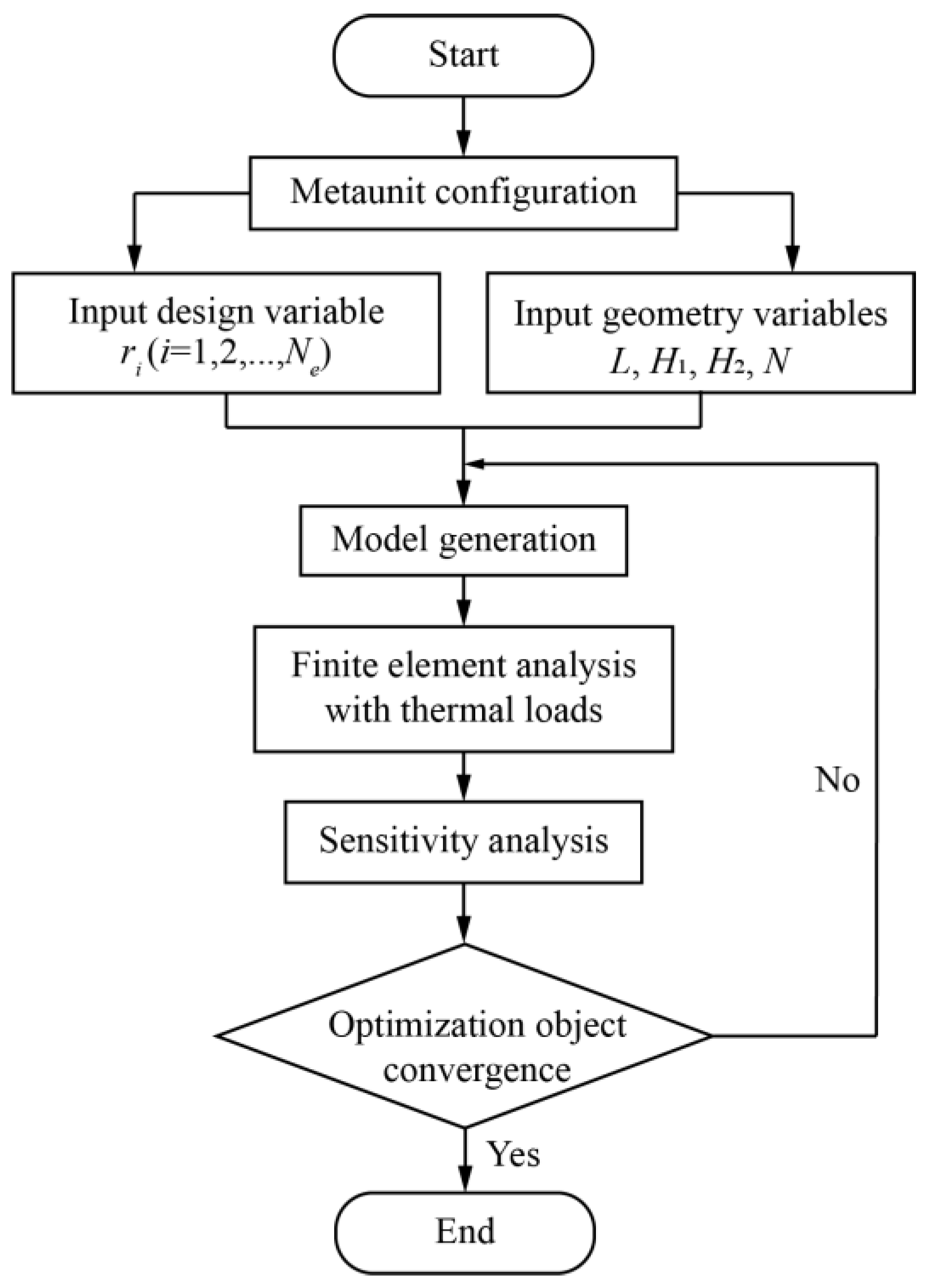
3. Structural Optimization Algorithm

3.1. Formulation of Optimization Problems

As shown in Figure 5, the metamaterial is assumed to be constructed with a circular beam. The inertial moment Iz and Iy, the polar moment of inertia J, and section area A are all corresponding to the beam radius ri (I = 1, …, Ne):
A r 2 ,   I y ,   I z r 4 ,   J r 4
Thus, ri is selected as the design variable in the optimization problems. Ne represents the total number of elements. The geometric constraints are also taken into consideration in the optimization problem. The nodes on the top and bottom surface are reinforced to maintain the flatness through constraining the variance of the thermal displacements. Assume the thermal displacements are uzk (k = 1, …, Np), and thus their variance D(uz) is expressed as:
D ( u z ) = 1 N p k = 1 N p u z k u ¯ z 2
where Np represents the number of nodes at the upper and lower surfaces, and u z represents the average value of uz.
Here, the optimization problem of minimizing effective ZTE in the thickness direction is formulated. The optimization formulation can be expressed as Equation (14):
f i n d :   r i , i = 1 , , N e M i n i m i z e :   u ¯ z s . t . KU = F D ( u z ) < ε r _ r i r ¯
The variance D(uz) is limited by a small number: ε = 1 × 10⁻⁴. The convergence criterion is set to be 0.01% of the objective function variation. u represents nodal displacement vector, and K, F represent the global stiffness matrix and global thermal force vector, i.e. the total global element stiffness matrix and force vector,
K = k ¯ e , F = f ¯ e

3.2. Sensitivity Analysis

In this paper, the Globally Convergent Method of Moving Asymptotes (GCMMA) [40] is adopted to solve the optimization problems. The gradient-based optimization solver needs to take the analytical sensitivity into consideration. The sensitivities of objective function u z and constraints D(uz) are deduced as:
u ¯ z r i = 1 N p k = 1 N p u z k r i
D ( u z ) r i = 1 N p k = 1 N p 2 u z k u ¯ z · u z k r i u ¯ z r i
Considering the FEM equilibrium equation, the sensitivities of displacement vector equals:
K r i U + K U r i = F r i U r i = K 1 F r i K r i U
Afterwards, the sensitivities of stiffness matrix K and load vector F are deduced. In each individual element, their sensitivities equal:
k e ¯ r i = T T k e r i T
f e ¯ r i = T T f e r i
Thus, the global sensitivities are simply an assembly of element sensitivities. The last step is to deduce the sensitivities of ke, fe and coordinate transformation matrix T:
k e r i = k e A A r i + k e I z I z r i + k e I y I y r i + k e I t J r i
f e r i = f e A A r i
After deducing the analytical sensitivities, the optimization procedure is performed as depicted in Figure 6. The absolute value of thermal displacement is considered as the objective function. As mentioned above, the initial variables are fed into the FEM calculation. The resultant parameters given by the FEM are then calculated to obtain the gradients in the sensitivity analysis step. The objective function can develop along the descending direction based on its gradients during the iteration until obtaining a converged result, i.e., the optimized objective function.

4. Results and Discussion

4.1. Meta-Units with NTE

In this section, several numerical examples are conducted to evaluate the performance of NTE in the thickness direction by the structural optimization method with the gradient-based algorithm. The initial temperature is set as T0 = 273.15 K, and then a temperature change of ∆T = T1T0 = 100 K is applied to the whole model. To calculate the free expansion in the thickness direction during the temperature change, the horizontal displacement freedom is constrained at the bottom. Each beam is divided into three elements, and the radius of the beam element is set as the variable in the optimization algorithm. The radius change range is 0.05 m ≤ ri ≤ 0.2 m. As depicted in Figure 7, the NTE performance of the unit cell is achieved by the optimization algorithm. The NTE of final optimized lattices in the thickness direction are −8.586 × 10⁻⁵ m/(m·K) for that of the hexagonal type and −5.576 × 10⁻⁵ m/(m·K) for that of the triangular type.

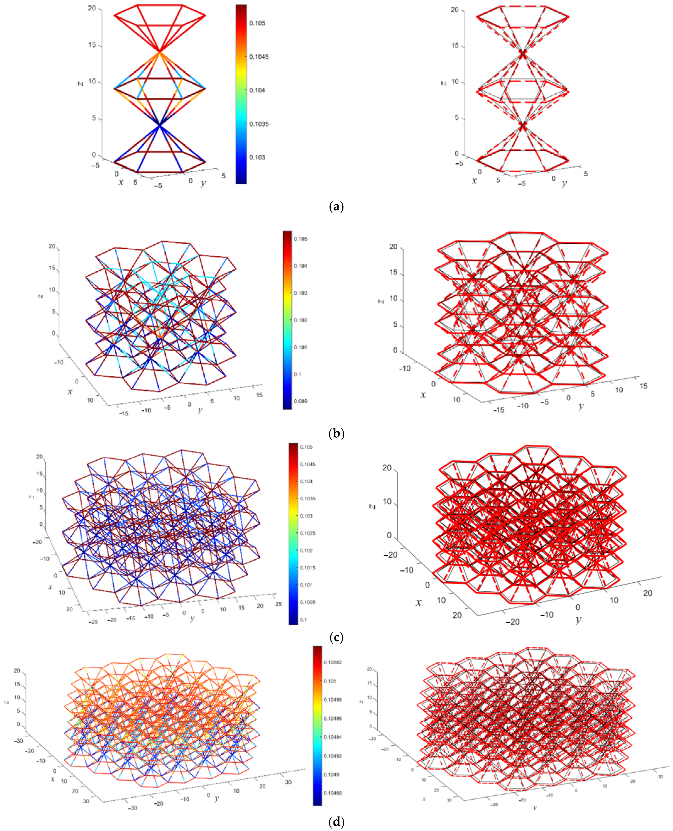
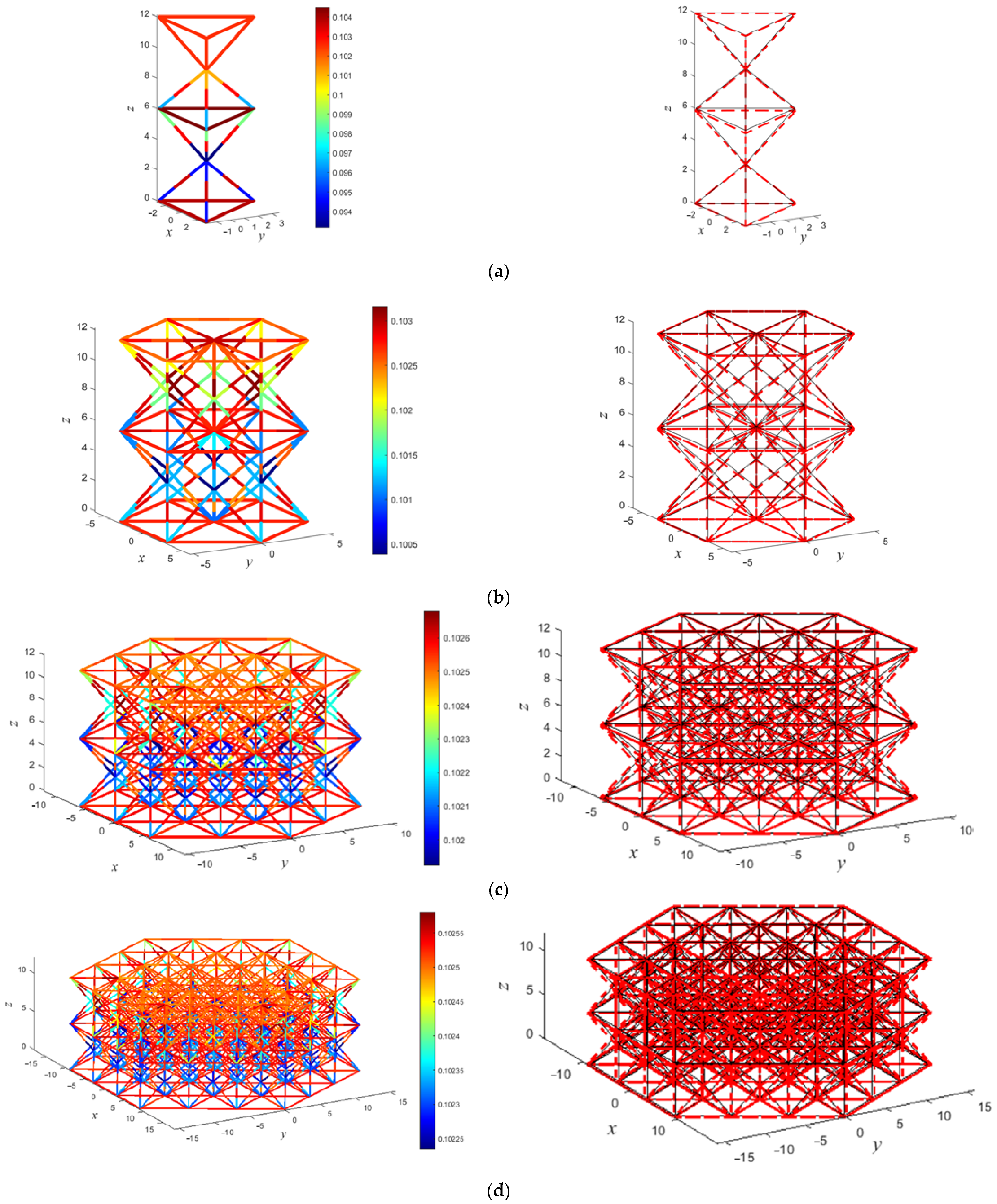
4.2. Near-ZTE Metamaterials

As mentioned in Section 2.2, the ZTE structure can be constructed by the way of stacking the PTE and NTE unit cells, as illustrated in Figure 3 and Figure 4. From the thermal-displacement Equation (12) in Section 3.1, the radius of beams is one of the key parameters which influenced the effective CTE attribution in the thickness direction. In this section, the beam radius is set as the design variable to optimize the lattices with near-ZTE. Not only the unit cells but also the corresponding circular array metamaterials are investigated. The convergence of the algorithm behaves well during the structure optimization process, as depicted in Figure 8.
Several optimization examples with different circular array numbers N are conducted by the numerical analysis procedure. N = 0 refers to the optimization result of a centered unit cell. One or more arrays of the metaunit are under the N control, in which the total scale increases as the number N increases. From the following cases shown in Figure 9 and Figure 10, the metastructure possessing extremely near-ZTE values around the order of 10−7 m/(m·K) are obtained. Furthermore, in comparison with each other, the unit cells have already reached at least a local optimum value. The results of the lattice with a larger scale have negligible changes, i.e., the results of the lattice array replicate the metaunit results.
The near-ZTE results are listed in Table 2. The comparison of results shows that the effective CTEs of the triangular lattice are higher than those of the hexagonal lattice. Recalling that the performance of the NTE triangle unit is weaker than that of the hexagonal unit (Section 4.1), the dual-layer structure enlarges their difference. The source of this difference can be traced back to the connection and topology of the lattice structure. Fortunately, the ZTE performance can be further improved by tuning the heights of different layers. This will be discussed in the next section.

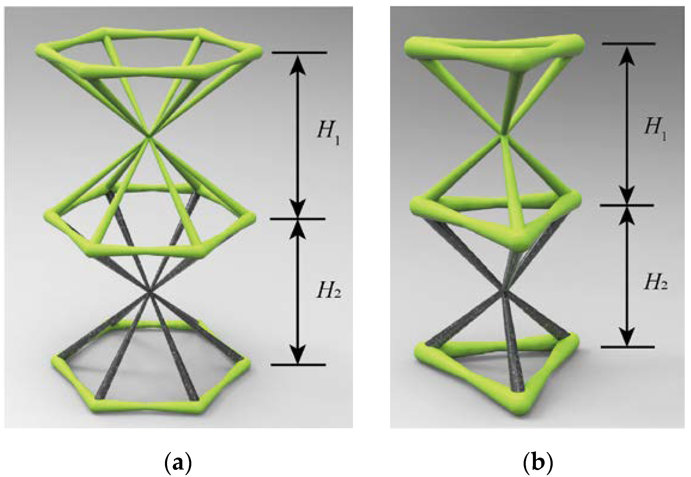
4.3. Height Optimization to Achieve a ZTE Metamaterial

The height of the unit cells is an obviously critical geometry parameter during the ZTE design. In order to intuitively sketch the influence, the simplest model of a triangle with all DOF constraints at the top node is studied, which is shown in Figure 1. The CFRP-nylon and nylon mentioned in Table 1 are given to the hypotenuse and the brace, respectively. The height of the triangle can be solved by the Pythagorean theorem. Consequently, according to Equation (5), the CTE curve with respect to the geometry height is illustrated in Figure 11. It is obvious that the height parameter can lead PTE and NTE attributes in different values. Based on this finding, the design space of a near-ZTE structure can be found.
Using the structural optimization method, the PTE lattice height H1 and NTE lattice height H2 are adjusted, as shown in Figure 3, at the reasonable boundaries to calculate the effective thermal displacement in the thickness direction. As shown in Figure 12, the thermal displacement in the thickness direction with variable height parameters is drawn. When a ZTE plane is inserted into the plot, a ZTE curve can be obtained by corresponding to different height parameters, as depicted in Figure 13. Table 3 lists several height-dominated optimization results with the different height ratios. Compared to Table 2, the effective CTE is further reduced to the order of about 10−9 by considering the optimal height ratio.
In addition, as the array number increases, the local bending caused by geometry constraints and bi-material composition becomes more and more apparent theoretically. The effective thermal displacement of the metamaterials with various array numbers under different ratios of H1 and H2 are investigated, and the trend map is depicted in Figure 14. The numerical results show that the array number does not affect the height ratio to ZTE very much. This result shows that a unit-cell level optimization may provide sufficient information to seek a ZTE metamaterial.

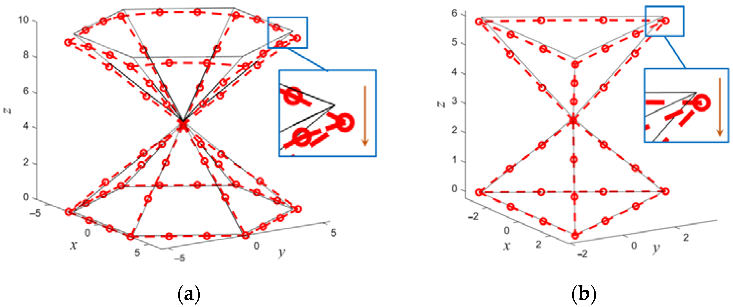
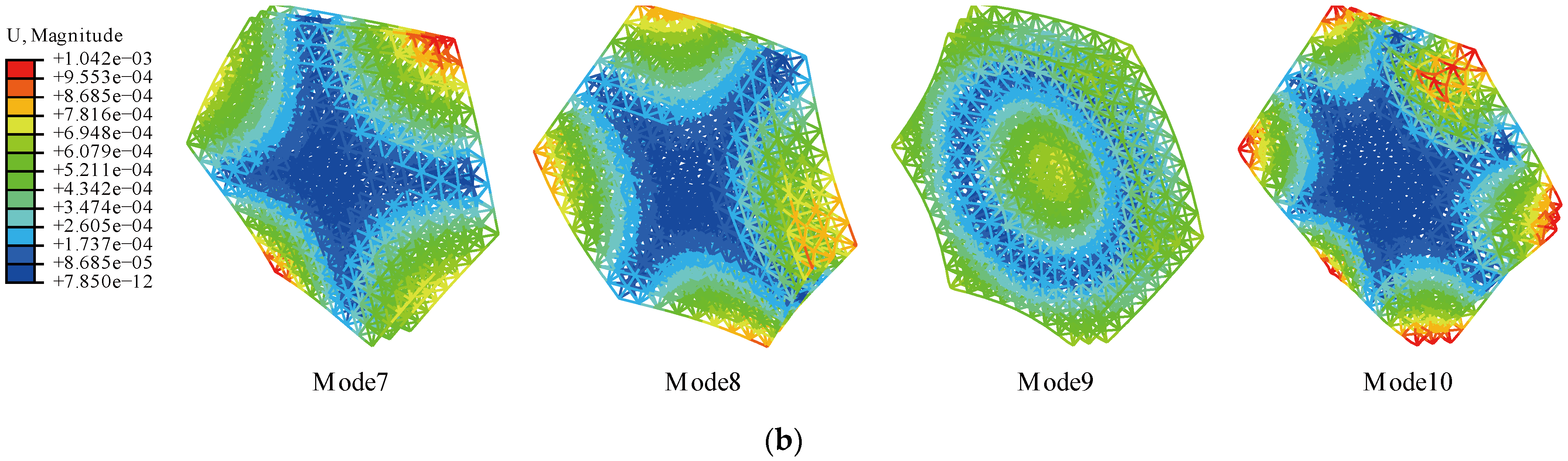
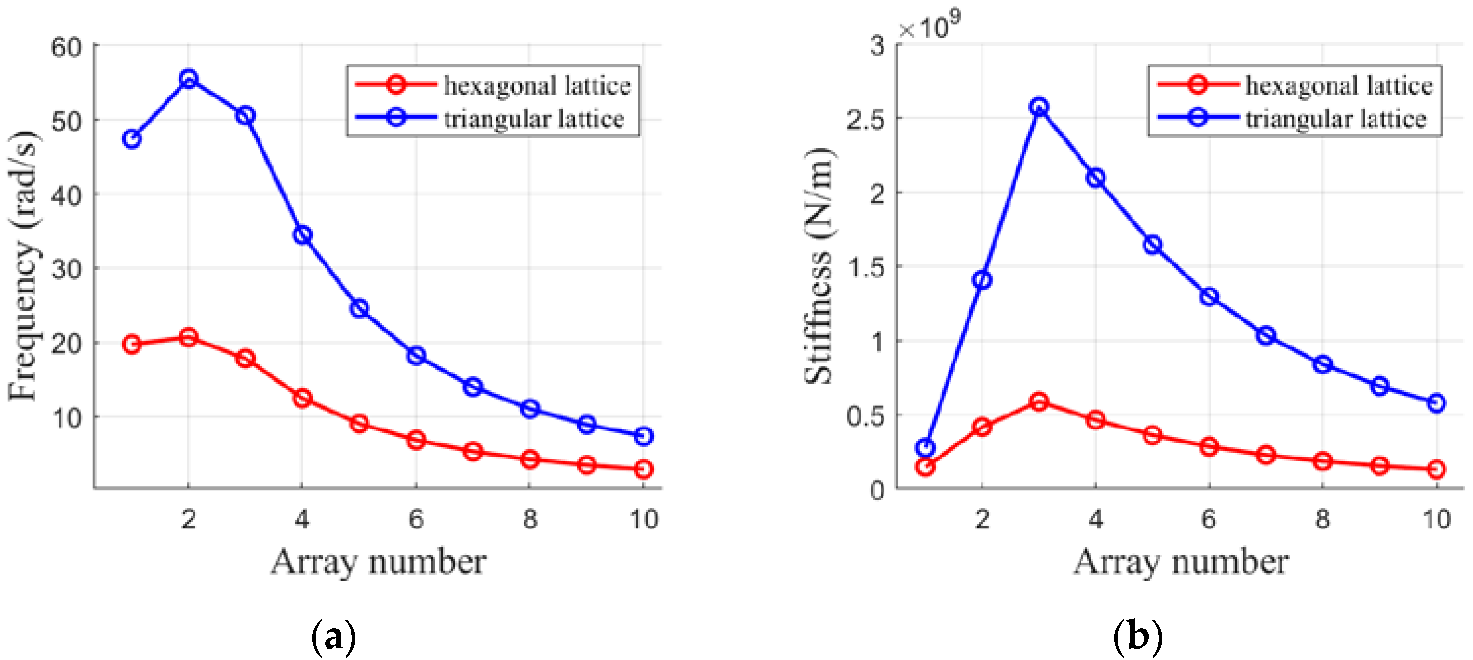
4.4. Modal Analysis of ZTE Lattices with Free Boundary Condition

A structure modal analysis is performed under a free boundary condition to obtain the natural frequencies and mode shapes of the metastructure. The FEM procedure is used for the modal analysis. In consideration of the space operation environment, there is no displacement constraint or inertial force applied to it. Next, the Lanczos method is adopted to solve eigenvalues to calculate the natural frequencies [41]. Because of the boundary condition, the first six eigenmodes represent the rigid body motion and are disregarded. The seventh to tenth eigenmodes are shown in Figure 15. The seventh eigenfrequency represents the natural frequency of the structure. Its relation corresponding to the array number is investigated, as shown in Figure 16. It shows that the frequency increases first and then drops as the array number N increases, as depicted in Figure 16a. The natural frequency is a crucial factor for orbit and attitude control [42]. Furthermore, the effective stiffness is plotted in Figure 16b. The effective stiffness is actually calculated by the scaling of 2 π f = K / m . The structural stiffness starts to drop as the circular array layer number N moves beyond 3 and the structure becomes large and flexible.

5. Conclusions

A novel near-ZTE metastructure design composed of bi-material hourglass unit cells is proposed by the structural optimization method with a gradient-based algorithm. The thermomechanical performances of the structures with different sensitive parameters and configurations are carried out. The conclusions are as follows:
(1)
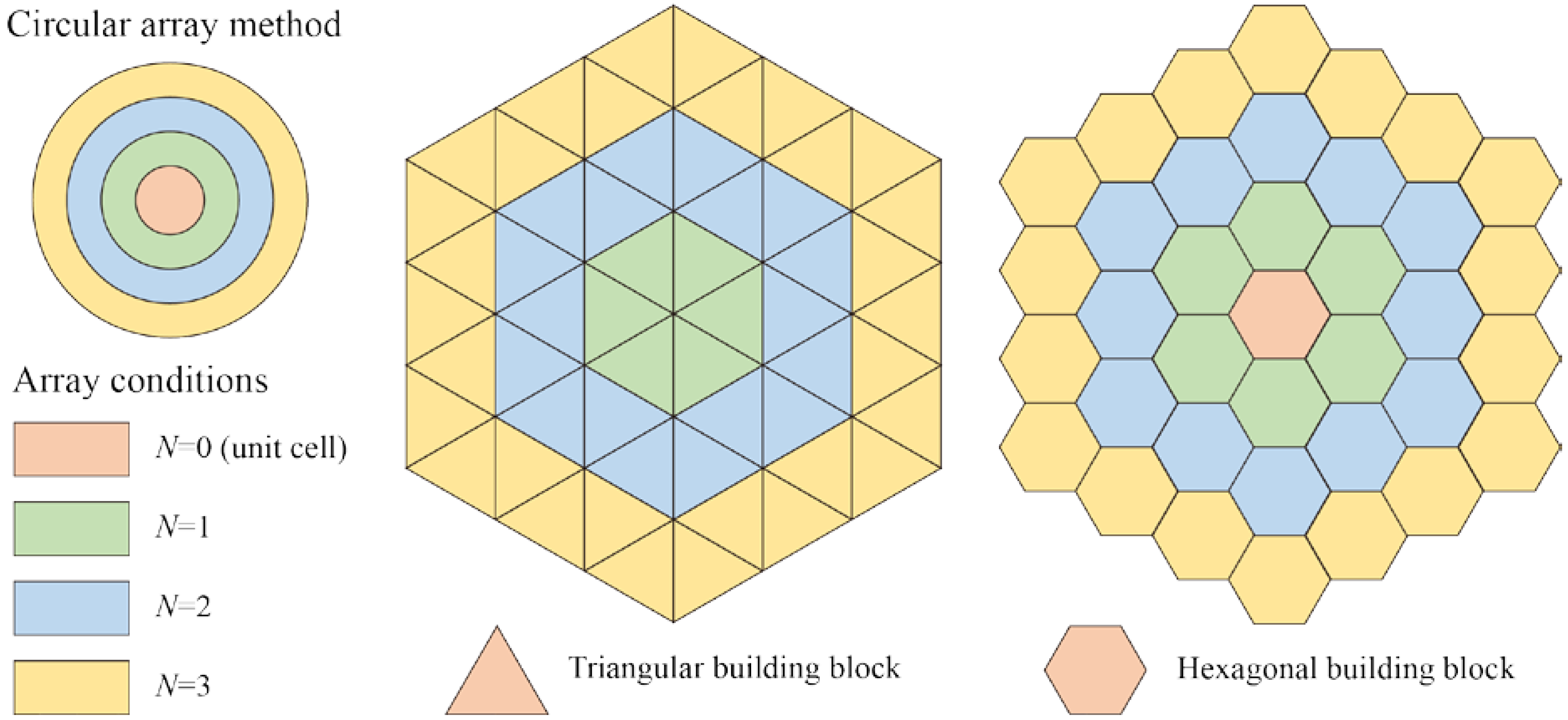
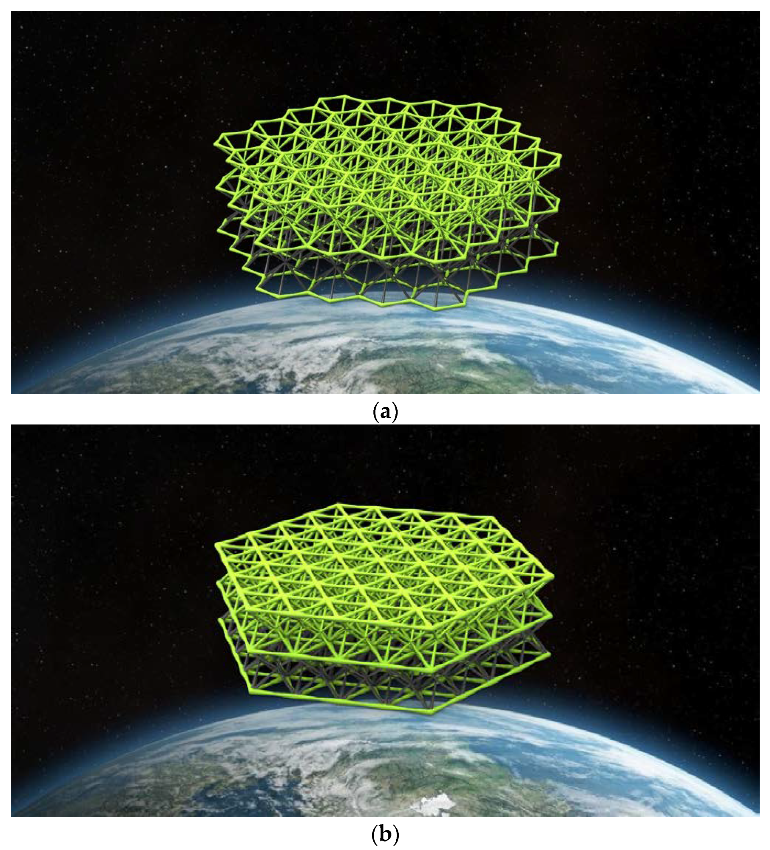
To satisfy the utilization requirement for structures such as a space telescope and apertures, the circular array condition is considered for the metastructure construction. The hexagonal and triangular configurations built from triangle units is considered as the building blocks.
(2)
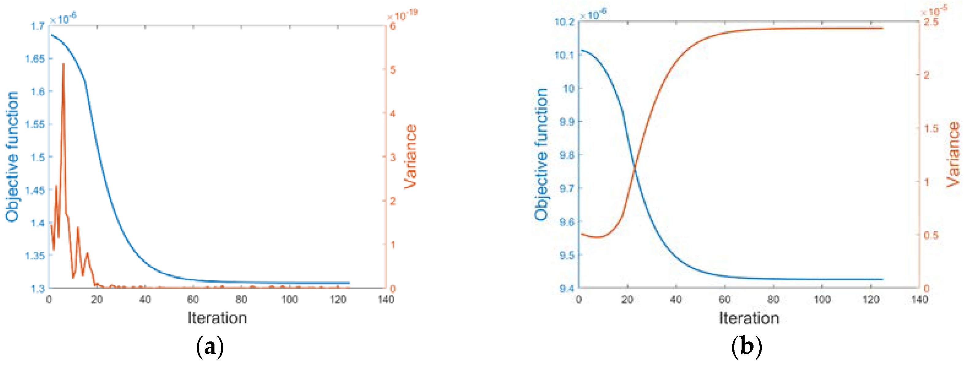
By analyzing the thermomechanical macroscopic properties, the beam radius and layer height ratio are selected as sensitive parameters during the optimization calculation. The optimization results show an excellent near-ZTE capacity in the thickness direction, with the magnitudes of about 10−9 m/(m·K).
(3)
The CTE of metastructures with diverse array numbers are investigated in a specific temperature change. A replication behavior is found in two configurations, i.e., the divergence due to the array number is insensitive to the structural thermal expansion. Therefore, a preliminary ZTE optimal result for a large-scale structure design can be conducted at the unit cell scale at a relatively low cost.
(4)
Focusing on orbit and attitude control, the natural frequencies are obtained by modal analysis. It is shown that the larger the size, the more flexible the structure behaves.
This study aims to provide a novel design composed of a dual-layer bi-material hourglass lattice metamaterial with near-ZTE behaviors in the thickness direction. It shows great potential in maintaining the optimal precision demands of space architectures under a harsh thermal environment. The design provides a novel solution for the design of large-scale space structures, such as RF apertures, reflector antennas, and space telescopes. In particular, this type of space structure can be fabricated by the additive manufacturing technology directly on orbit in the near future [43].

Author Contributions

Conceptualization, B.Y. and H.Z.; methodology, B.Y. and Z.X.; software, B.Y.; validation, B.Y., Z.X. and R.M.; formal analysis, B.Y. and H.Z.; investigation B.Y., Z.X. and R.M.; resources, H.Z. and A.W.; data curation, B.Y.; writing—original draft preparation, B.Y.; writing—review and editing, H.Z., A.W. and Z.X.; visualization, B.Y.; supervision, H.Z.; project administration, H.Z.; funding acquisition, H.Z. All authors have read and agreed to the published version of the manuscript.

Funding

H.F. Zhao acknowledges the support of the China Manned Space Engineering Program and the Innovative Research Fund of the Chinese Academy of Sciences through Grant No. JCPYJJ-22002. R.N. Mu acknowledges the support from the Innovative Research Fund of the Key Laboratory of Space Utilization, Chinese Academy of Sciences, under Grant No. CSU-JJKT-2020-5.

Institutional Review Board Statement

Not applicable.

Informed Consent Statement

Not applicable.

Data Availability Statement

The datasets generated that support the findings of this article are available from the corresponding author upon request.

Conflicts of Interest

The authors declare that they have no conflicts of interest.

References

  1. Anderson, B.; Justus, C.; Batts, G. Guidelines for the Selection of Near-Earth Thermal Environment Parameters for Spacecraft Design. (No. NASA/TM-2001-211221). 2001. Available online: https://ntrs.nasa.gov/citations/20020004360 (accessed on 2 January 2023).
  2. Justus, C.G.; Batts, G.W.; Anderson, B.J.; James, B.F. Simple Thermal Environment Model (STEM) User’s Guide. (No. NAS 1.15: 211222). 2001. Available online: https://ntrs.nasa.gov/citations/20020001443 (accessed on 2 January 2023).
  3. Ghidini, T. Materials for space exploration and settlement. Nat. Mater. 2018, 17, 846–850. [Google Scholar] [CrossRef] [PubMed]
  4. Iqbal, M. An Introduction to Solar Radiation; Academic Press: Cambridge, MA, USA, 1983. [Google Scholar] [CrossRef]
  5. Lu, G.-Y.; Zhou, J.-Y.; Cai, G.-P.; Fang, G.-Q.; Lv, L.-L.; Peng, F.-J. Studies of thermal deformation and shape control of a space planar phased array antenna. Aerosp. Sci. Technol. 2019, 93, 105311. [Google Scholar] [CrossRef]
  6. Bhundiya, H.G.; Royer, F.; Cordero, Z. Engineering Framework for Assessing Materials and Processes for In-Space Manufacturing. J. Mater. Eng. Perform. 2022, 31, 6045–6059. [Google Scholar] [CrossRef]
  7. Timoshenko, S. Analysis of Bi-Metal Thermostats. J. Opt. Soc. Am. 1925, 11, 233–255. [Google Scholar] [CrossRef]
  8. Lakes, R. Cellular solids with tunable positive or negative thermal expansion of unbounded magnitude. Appl. Phys. Lett. 2007, 90, 221905. [Google Scholar] [CrossRef] [Green Version]
  9. Wu, L.; Li, B.; Zhou, J. Isotropic Negative Thermal Expansion Metamaterials. ACS Appl. Mater. Interfaces 2016, 8, 17721–17727. [Google Scholar] [CrossRef] [Green Version]
  10. Yu, H.; Liang, B.; Zhao, Z.; Liu, P.; Lei, H.; Song, W.; Chen, M.; Guo, X. Metamaterials with a controllable thermal-mechanical stability: Mechanical designs, theoretical predictions and experimental demonstrations. Compos. Sci. Technol. 2021, 207, 108694. [Google Scholar] [CrossRef]
  11. Jefferson, G.; Parthasarathy, T.A.; Kerans, R.J. Tailorable thermal expansion hybrid structures. Int. J. Solids Struct. 2009, 46, 2372–2387. [Google Scholar] [CrossRef]
  12. Wei, K.; Peng, Y.; Wen, W.; Pei, Y.; Fang, D. Tailorable Thermal Expansion of Lightweight and Robust Dual-Constituent Triangular Lattice Material. J. Appl. Mech. 2017, 84, 101006. [Google Scholar] [CrossRef]
  13. Wang, K.; Chen, J.; Han, Z.; Wei, K.; Yang, X.; Wang, Z.; Fang, D. Synergistically program thermal expansional and mechanical performances in 3D metamaterials: Design-Architecture-Performance. J. Mech. Phys. Solids 2022, 169, R713–R715. [Google Scholar] [CrossRef]
  14. Peng, Y.; Wei, K.; Mei, M.; Yang, X.; Fang, D. Simultaneously program thermal expansion and Poisson’s ratio in three dimensional mechanical metamaterial. Compos. Struct. 2020, 262, 113365. [Google Scholar] [CrossRef]
  15. Xu, Z.; Zhao, H.; Wang, K. Design of hourglass-lattice metastructure with near-zero thermal expansion using structural optimization method. Eng. Struct. 2023, 277, 115374. [Google Scholar] [CrossRef]
  16. He, X.; Yu, J.; Xie, Y. Bi-Material Re-Entrant Triangle Cellular Structures Incorporating Tailorable Thermal Expansion and Tunable Poisson’s Ratio. J. Mech. Robot. 2019, 11. [Google Scholar] [CrossRef]
  17. Takezawa, A.; Kobashi, M.; Kitamura, M. Porous composite with negative thermal expansion obtained by photopolymer additive manufacturing. APL Mater. 2015, 3, 076103. [Google Scholar] [CrossRef]
  18. Hirota, M.; Kanno, Y. Optimal design of periodic frame structures with negative thermal expansion via mixed integer programming. Optim. Eng. 2015, 16, 767–809. [Google Scholar] [CrossRef]
  19. Yang, Z.; Zhang, Y.; Liu, S.; Wu, Z. Design and analysis of dual-constituent lattice sandwich panel with in-plane zero thermal expansion and high structural stiffness. Mech. Adv. Mater. Struct. 2019, 28, 1743–1754. [Google Scholar] [CrossRef]
  20. Steeves, C.A.; Lucato, S.L.D.S.E.; He, M.; Antinucci, E.; Hutchinson, J.W.; Evans, A.G. Concepts for structurally robust materials that combine low thermal expansion with high stiffness. J. Mech. Phys. Solids 2007, 55, 1803–1822. [Google Scholar] [CrossRef] [Green Version]
  21. Steeves, C.A.; Mercer, C.; Antinucci, E.; He, M.Y.; Evans, A.G. Experimental investigation of the thermal properties of tailored expansion lattices. Int. J. Mech. Mater. Des. 2009, 5, 195–202. [Google Scholar] [CrossRef] [Green Version]
  22. Hopkins, J.B.; Lange, K.J.; Spadaccini, C.M. Synthesizing the Compliant Microstructure of Thermally Actuated Materials Using Freedom, Actuation, and Constraint Topologies. In International Design Engineering Technical Conferences and Computers and Information in Engineering Conference; American Society of Mechanical Engineers: Chicago, IL, USA, 2012. [Google Scholar]
  23. Parsons, E.M. Lightweight cellular metal composites with zero and tunable thermal expansion enabled by ultrasonic additive manufacturing: Modeling, manufacturing, and testing. Compos. Struct. 2019, 223, 110656. [Google Scholar] [CrossRef]
  24. Wei, K.; Chen, H.; Pei, Y.; Fang, D. Planar lattices with tailorable coefficient of thermal expansion and high stiffness based on dual-material triangle unit. J. Mech. Phys. Solids 2016, 86, 173–191. [Google Scholar] [CrossRef]
  25. Wei, K.; Xiao, X.; Xu, W.; Han, Z.; Wu, Y.; Wang, Z. Large programmable coefficient of thermal expansion in additively manufactured bi-material mechanical metamaterial. Virtual Phys. Prototyp. 2021, 16, S53–S65. [Google Scholar] [CrossRef]
  26. Wei, K.; Peng, Y.; Wang, K.; Duan, S.; Yang, X.; Wen, W. Three dimensional lightweight lattice structures with large positive, zero and negative thermal expansion. Compos. Struct. 2018, 188, 287–296. [Google Scholar] [CrossRef]
  27. Takezawa, A.; Kobashi, M. Design methodology for porous composites with tunable thermal expansion produced by multi-material topology optimization and additive manufacturing. Compos. Part B Eng. 2017, 131, 21–29. [Google Scholar] [CrossRef]
  28. Ruder, S. An overview of gradient descent optimization algorithms. arXiv 2016, arXiv:1609.04747. [Google Scholar]
  29. Haji, S.H.; Abdulazeez, A. Comparison of optimization techniques based on gradient descent algorithm: A review. PalArch’s J. Archaeol. Egypt/Egyptol. 2021, 18, 2715–2743. [Google Scholar]
  30. Galántai, A. The theory of Newton’s method. J. Comput. Appl. Math. 2000, 124, 25–44. [Google Scholar] [CrossRef] [Green Version]
  31. Polyak, B.T. Newton’s method and its use in optimization. Eur. J. Oper. Res. 2007, 181, 1086–1096. [Google Scholar] [CrossRef]
  32. Shewchuk, J.R. An introduction to the Conjugate Gradient Method without the Agonizing Pain; Department of Computer Science Pittsburgh, Carnegie-Mellon University: Pittsburgh, PA, USA, 1994. [Google Scholar]
  33. Nocedal, J.; Wright, S.J. Conjugate Gradient Methods; Springer: New York, NY, USA, 2006; pp. 101–134. [Google Scholar]
  34. Miller, W.; MacKenzie, D.S.; Smith, C.W.; Evans, K.E. A generalised scale-independent mechanism for tailoring of thermal expansivity: Positive and negative. Mech. Mater. 2008, 40, 351–361. [Google Scholar] [CrossRef]
  35. Miller, W.; Smith, C.W.; MacKenzie, D.S.; Evans, K.E. Negative thermal expansion: A review. J. Mater. Sci. 2009, 44, 5441–5451. [Google Scholar] [CrossRef]
  36. Zienkiewicz, O.C.; Taylor, R.L. The Finite Element Method for Solid and Structural Mechanics, 6th ed.; Butterworth-Heinemann: Oxford, UK, 2005. [Google Scholar]
  37. Pérès, P.; Dupillier, J.M.; Defoort, B. Thermoplastic Composite Structures for Space Applications: Manufacturing Process Simulation. In Proceedings of the ECCM16-16th European Conference on Composite Materials, Seville, Spain, 22–26 June 2014. [Google Scholar]
  38. Milton, G.W. The Theory of Composites; Cambridge University Press: Cambridge, UK, 2002. [Google Scholar]
  39. Gardner, J.P.; Mather, J.C.; Clampin, M.; Doyon, R.; Greenhouse, M.A.; Hammel, H.B.; Hutchings, J.B.; Jakobsen, P.; Lilly, S.J.; Long, K.S.; et al. The james webb space telescope. Space Sci. Rev. 2006, 123, 485–606. [Google Scholar] [CrossRef] [Green Version]
  40. Zhang, W.H.; Fleury, C.; Duysinx, P.; Nguyen, V.H.; Laschet, I. A generalized method of moving asymptotes (GMMA) including equality constraints. Struct. Multidiscip. Optim. 1996, 12, 143–146. [Google Scholar] [CrossRef]
  41. Paige, C.C. Computational Variants of the Lanczos Method for the Eigenproblem. IMA J. Appl. Math. 1972, 10, 373–381. [Google Scholar] [CrossRef]
  42. Rajasingh, C.; Shrivastava, S.K. Orbit and attitude control of a geostationary inertially oriented large flexible plate-like spacecraft. Acta Astronaut. 1987, 15, 823–832. [Google Scholar] [CrossRef]
  43. Hoyt, R.P. SpiderFab: An Architecture for Self-Fabricating Space Systems; American Institute of Aeronautics and Astronautics: Reston, VA, USA, 2013. [Google Scholar] [CrossRef] [Green Version]
Figure 1. Schematic illustration of the thermal expansion deformation of a triangle cell: (a) initial shape (b) shape after heating.
Aerospace 10 00294 g001
Figure 2. Schematic illustration of the bi-material single-layer hourglass unit cell: (a) hexagon type; (b) triangle type.
Aerospace 10 00294 g002
Figure 3. Schematic illustration of the dual-layer unit cell (a) hexagon type; (b) triangle type.
Aerospace 10 00294 g003
Figure 4. Lattice structure constructed with the circular array method. (Note: the triangle type does not have the centered cell of N = 0.).
Aerospace 10 00294 g004
Figure 5. Schematic illustration of bi-material dual-layer hourglass under the circular array; (a) hexagon type; (b) triangle type.
Aerospace 10 00294 g005
Figure 6. Flowchart of optimization procedure.
Aerospace 10 00294 g006
Figure 7. Optimization result of hourglass unit cell with a negative thermal deformation: (a) hexagonal type; (b) triangular type. Note: the circular dot represents the FEM nodes of a beam element.
Aerospace 10 00294 g007
Figure 8. Convergence curve of the objective function and variance constraint of the (a) hexagonal type; and (b) triangular type.
Aerospace 10 00294 g008
Figure 9. Schematic illustration of optimized results and thermal deformation of the hexagonal hourglass lattice: (a) N = 0, CTE = 5.727 × 10⁻⁷ m/(m·K); (b) N = 1, CTE = 5.457 × 10⁻⁷ m/(m·K); (c) N = 2, CTE = 5.433 × 10⁻⁷ m/(m·K); (d) N = 3, CTE = 5.202 × 10⁻⁷ m/(m·K).
Aerospace 10 00294 g009
Figure 10. Thermal deformation of triangular hourglass lattice: (a) N = 0, CTE = 2.582 × 10⁻⁶ m/(m·K); (b) N = 1, CTE = 2.566 × 10⁻⁶ m/(m·K); (c) N = 2, CTE = 2.559 × 10⁻⁶ m/(m·K); (d) N = 3, CTE = 2.558 × 10⁻⁶ m/(m·K).
Aerospace 10 00294 g010
Figure 11. CTE variance with respect to the geometry design.
Aerospace 10 00294 g011
Figure 12. Thermal displacement with variable H1 and H2 in (a) a hexagonal hourglass lattice; and (b) a triangular hourglass lattice.
Aerospace 10 00294 g012
Figure 13. ZTE curve with variable H1 and H2.
Aerospace 10 00294 g013
Figure 14. Trend map of height optimization result: (a) hexagonal hourglass lattice (b) triangular hourglass lattice.
Aerospace 10 00294 g014
Figure 15. Modal analysis and the mode shapes of a space structure in freedom (a) hexagonal hourglass lattice (b) triangle hourglass lattice.
Aerospace 10 00294 g015aAerospace 10 00294 g015b
Figure 16. Natural frequency variation with respect to array numbers (a) frequency curve (b) stiffness curve.
Aerospace 10 00294 g016
Table 1. Mechanical and thermal properties of the materials.
MaterialElastic Modulus
(GPa)
Poisson’s RadioDensity
(kg/m3)
CTE
(m/m·K)
Nylon4.90.3813004.4 × 10−5
CFRP-Nylon15.90.3311607.4 × 10−6
Table 2. Results of effective CTE in the thickness direction under different circular arrays.
Metamaterial
Type
Array
Number
Overall Diameter
(m)
Max Radius
(m)
Min Radius
(m)
Effective CTE
(m/m·K)
Hexagonal
dual-layer
hourglass lattice
010.3920.20.055.727 × 10−7
131.1770.20.055.457 × 10−7
251.9610.20.055.433 × 10−7
372.7460.20.055.202 × 10−7
Triangular
dual-layer
hourglass lattice
03.4640.20.052.582 × 10−6
112.0000.20.052.566 × 10−6
224.0000.20.052.559 × 10−6
336.0000.20.052.558 × 10−6
Table 3. Results of effective CTE in thickness direction in several height parameters.
Metamaterial TypeH1 (m)H2 (m)Effective CTE (m/m·K)
Hexagonal dual-layer
hourglass lattice
6.5013.471.814 × 10−8
9.9210.087.115 × 10−9
14.617.271.374 × 10−8
Triangular dual-layer
hourglass lattice
3.388.148.069 × 10−9
6.045.402.250 × 10−8
10.083.242.049 × 10−9
Disclaimer/Publisher’s Note: The statements, opinions and data contained in all publications are solely those of the individual author(s) and contributor(s) and not of MDPI and/or the editor(s). MDPI and/or the editor(s) disclaim responsibility for any injury to people or property resulting from any ideas, methods, instructions or products referred to in the content.

