The following section presents the results of optimising the interface designs for improved energy absorption and structural integrity.
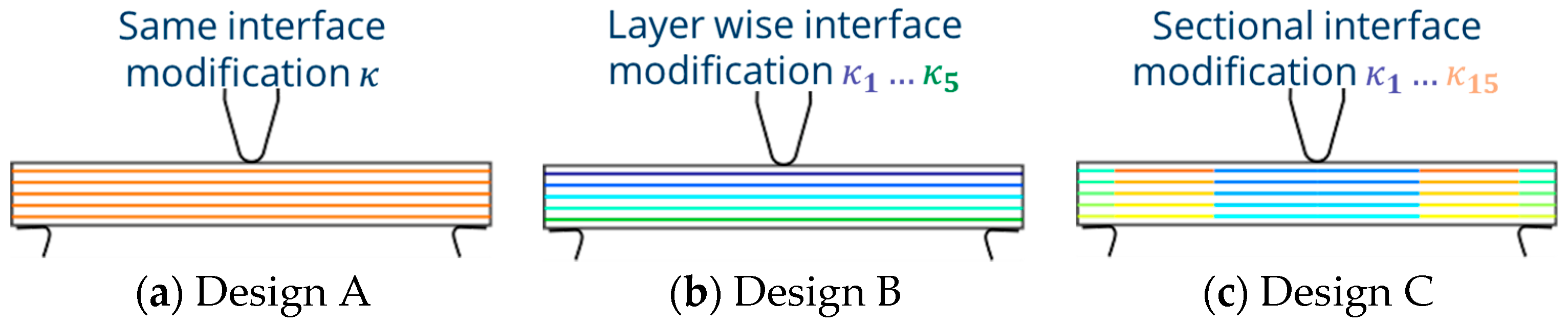
3.2.1. Design A (Same Layer-by-layer Interface Modification Concept—Figure 6a)
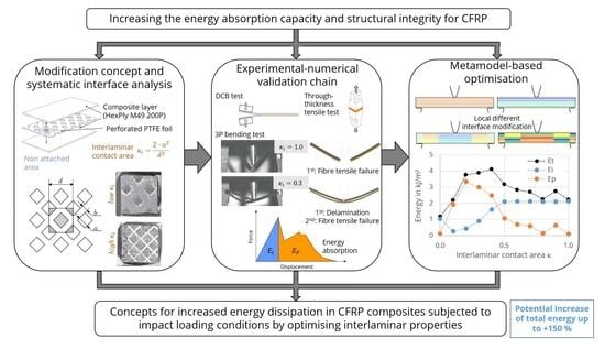
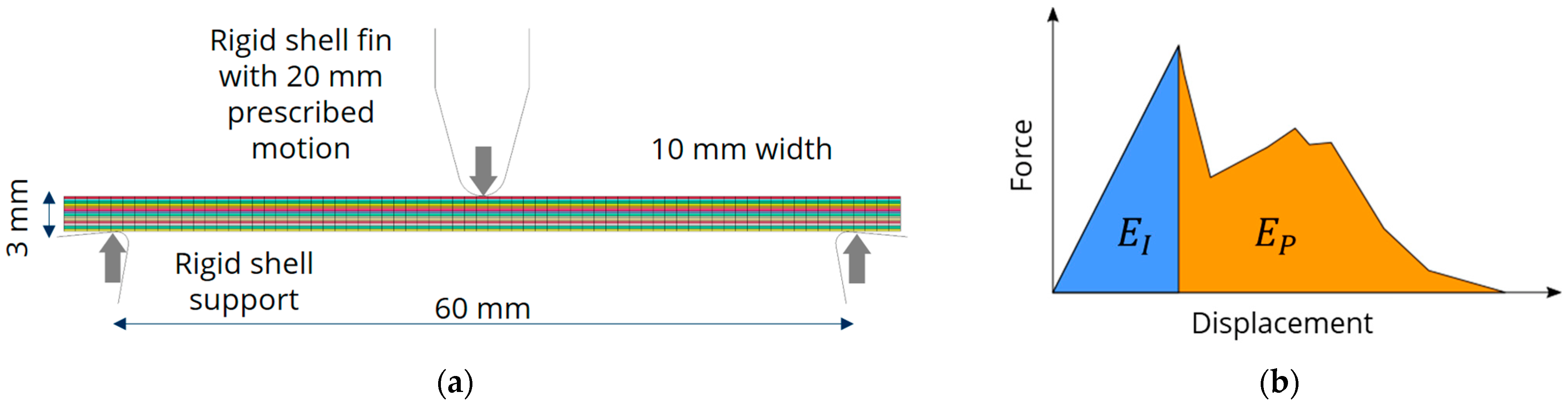
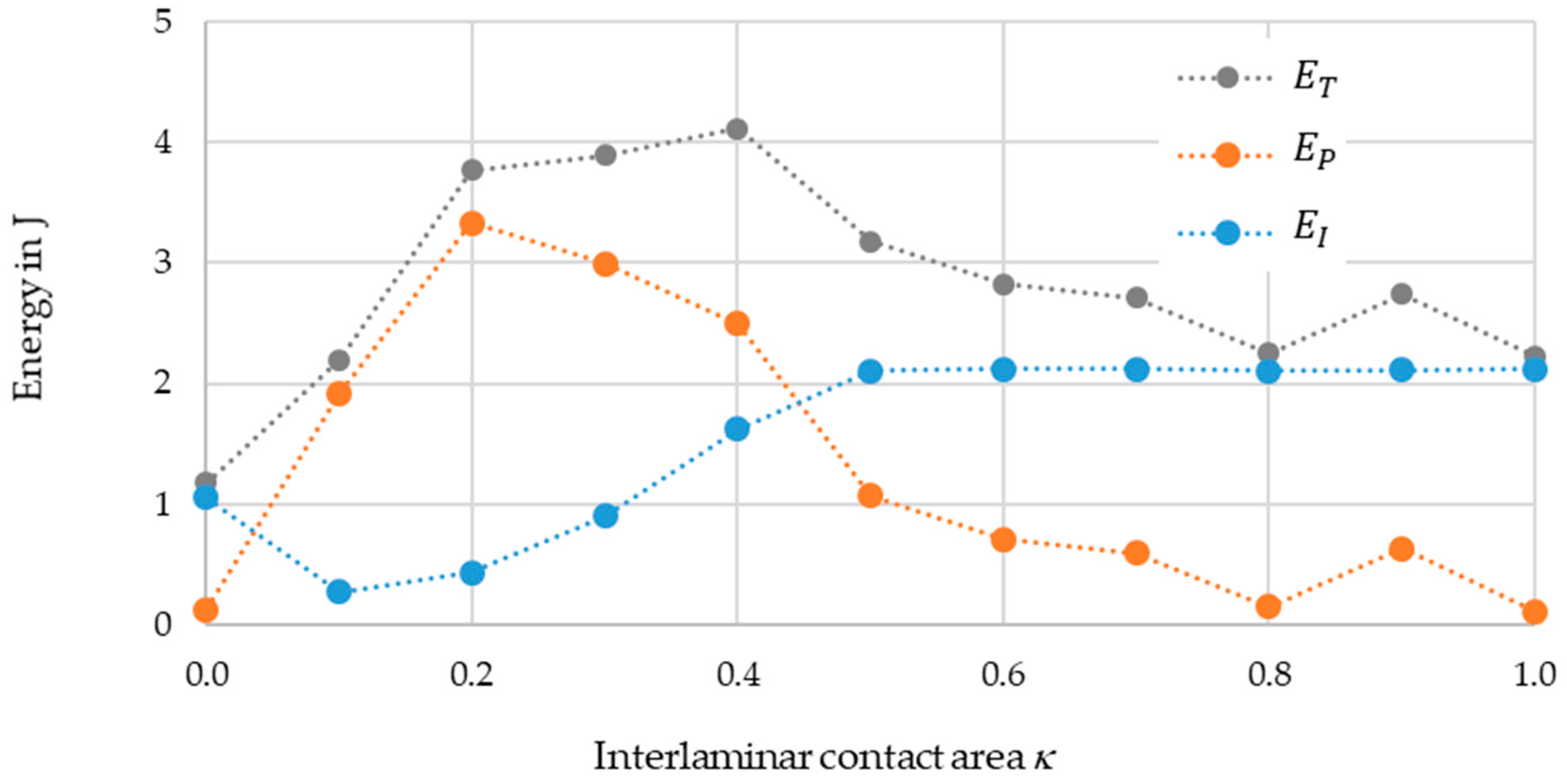
Figure 9 shows the energy absorption of the impact-loaded CFRP beam with different interlaminar contact areas
.
Figure 5b displays the various energies as functions of contact area. The total energy
ET is the sum of the initiation
EI and propagation energy
EP.
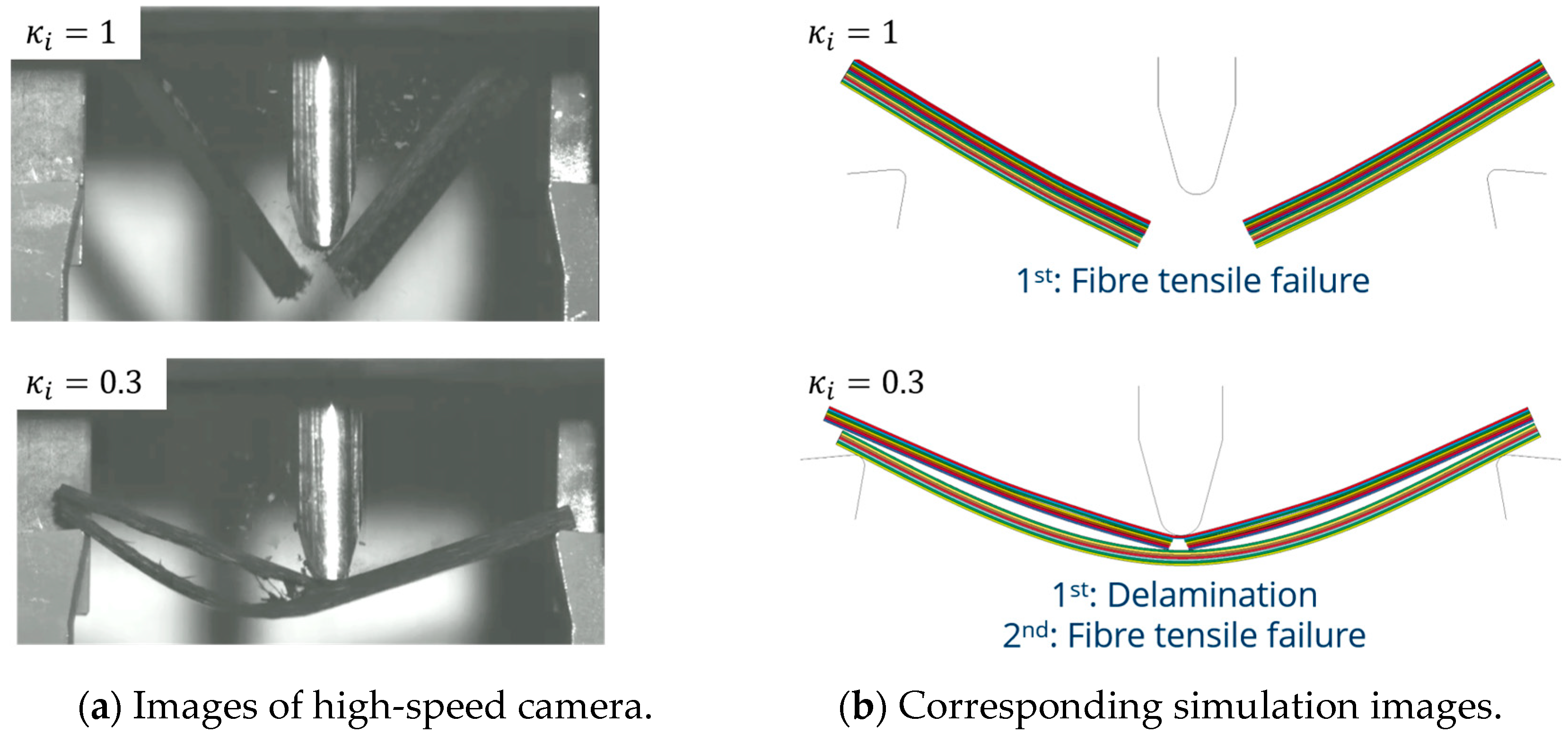
The simulation with a contact area ( shows a very compliant structural response, as the whole specimen is already delaminated in the simulation. It also shows no in-plane failure until the specimen slips through the support, and the force signal increases continuously from this point on. After the slippage, there is still some force transfer due to inertia and friction from the contact of the indenter with the specimen. However, these effects are neglectable; therefore, the energy absorption capacity of this interface modification is largely determined by the initiation energy.
From a κ of 0.1, EI increases as the force rises more steeply due to a higher initial stiffness. Compared to the case κ = 0.0, EI is lower for κ = 0.1. Although the maximum force is much higher, the displacement at maximum force is lower due to the much higher stiffness, resulting in lower EI. Since the interlaminar properties of strengths (t and s) and critical energy release rates (gic and giic) are very low, extensive delamination occurs in all five interfaces from the time the maximum force is reached. As a result, EP is significantly higher than EI. In general, this indicates that an increasing contact area leads to an increased EI due to the higher force maxima caused by increasing interlaminar strengths. However, at contact areas of 0.5 and above, the initial failure is no longer dominated by delamination failure, but by fibre failure. This is why the initiation energy remains almost constant from this interface modification onwards.
EP decreases starting from = 0.2. Due to increasing interface strengths, not all five modified interfaces delaminate and dissipate energy accordingly. Reduced delamination occurs since the initial failure is determined by the in-plane failure. This trend intensifies above a of 0.5. EP decreases with increasing interlaminar contact area and approaches zero. The small increase in the propagation energy at = 0.9 results from a subsequent force effect on the indenter due to a collision with the refracted beam arms and thus represents a numerical artefact.
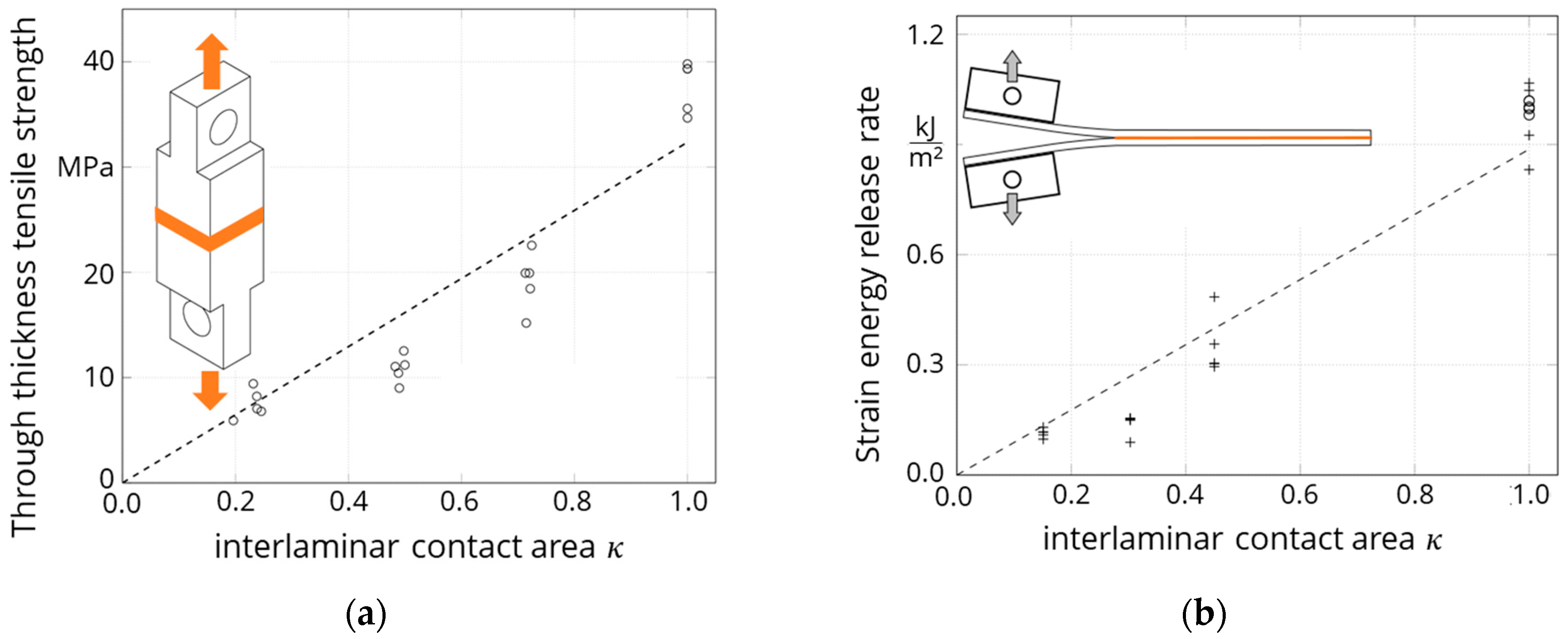
In reference [
10], the amounts for the interlaminar contact area are given as nominal values. For comparison with the simulations presented here, it is necessary to use the precise values for the specimens resulting from the manufacturing process.
Table 3 contains these values, and
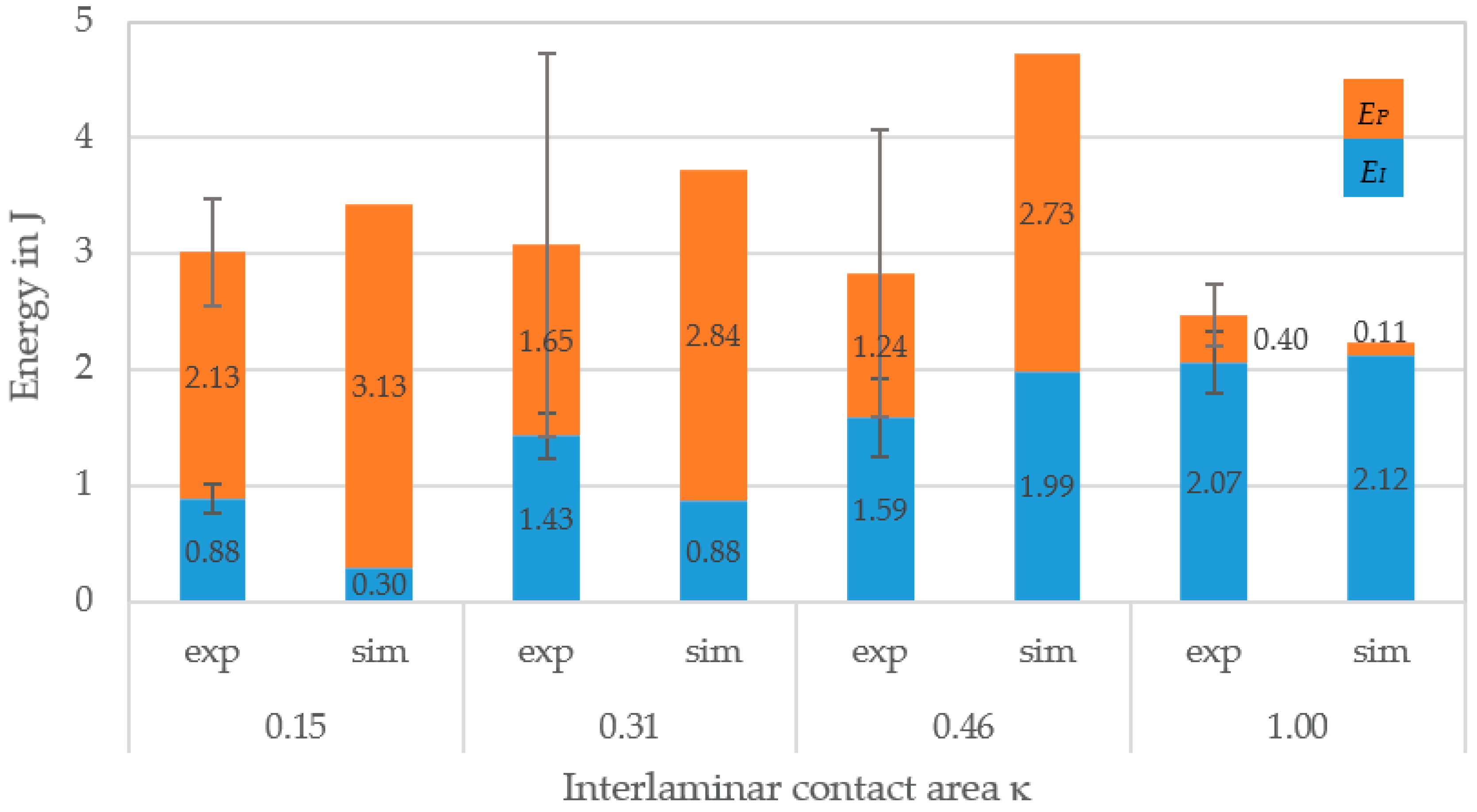
Figure 10 compares the results from [
10] with the simulation results based on the methods used here.
Generally, the numerical model is capable of reproducing the complex deformation and failure behaviour of the impact-loaded CFRP beams. The simulations significantly underestimate the initial energy for a small contact area
. The experimentally determined force–displacement curve is clearly nonlinear until the maximum force is reached. This rather gradual failure is explained by smaller delamination processes [
10]. In contrast, the simulations predict a strongly linear force–displacement curve until a sudden large-scale delamination failure, which leads to an abrupt drop in force and the corresponding lower
EI. For the case of
,
EI is overestimated by the simulation as delamination failure is predicted at a higher force. The model of a fully interlaminar contact area predicts
EI with very good agreement with the experimental values.
All simulations overestimate EP with the exception of the models with a of 1.0. This is caused by the symmetrical formation of delaminations. Nevertheless, ET as the sum of Ei and EP is predicted sufficiently well by the simulation models within the standard deviation of the experimental results, except for the results of . Due to the moderate interface properties, the energy absorption in this case is higher due to overestimated delaminations than in the simulation with smaller .
The inserted foil increases the mass of the tested samples by 6–8% according to the chosen interlaminar contact area. This is negligible compared to the scattering of the energies. The mass is not varied in the simulation because the thickness and density of the cohesive elements are not varied with .
The numerically derived data are used to calibrate the FNN metamodel. The accuracy of the metamodel for Design A’s concept is determined by the coefficient of determination
:
where
p is the number of data sets,
is the predicted total energy,
is the mean of the analysed total energy, and
is analysed total energy with respect to the parameter set
. The metamodel is then used to determine a parameter set
in which
is maximised. Mathematically, the task can be formulated as follows:
where no further constraints for
have to be fulfilled. An interlaminar contact area of 0.45 would result in the largest energy absorption of 4.9 J according to the metamodel predictions. This is an increase of about 120% compared to the reference model. Even if this value appears somewhat too optimistic due to the overestimated delamination energy, the simulation models and the applied metamodel-based optimisation confirm the results of the experimental investigations. The energy absorption can be significantly increased by the specific adjustment of the interlaminar properties and the resulting delamination behaviour.
3.2.3. Design C (Sectional Interface Modification—Figure 6c)
In the sectional interface modification, the five interfaces of the layer-wise concept are each divided into three sections, taking symmetry into account. For the creation of the metamodel, 205 parameter sets (
p) for the 15 interlaminar contact areas
with
are analysed. The developed metamodel has an accuracy
of 0.689. The driving assumption of design C is the identification of the influence of specific locations for interface modifications on the global energy dissipation. Therefore, the influence of
on the structural response of the three-point bending test is determined using a variance-based sensitivity analysis [
21]. A global sensitivity analysis (GSA) index is determined for each
, which describes the influence of the parameter on
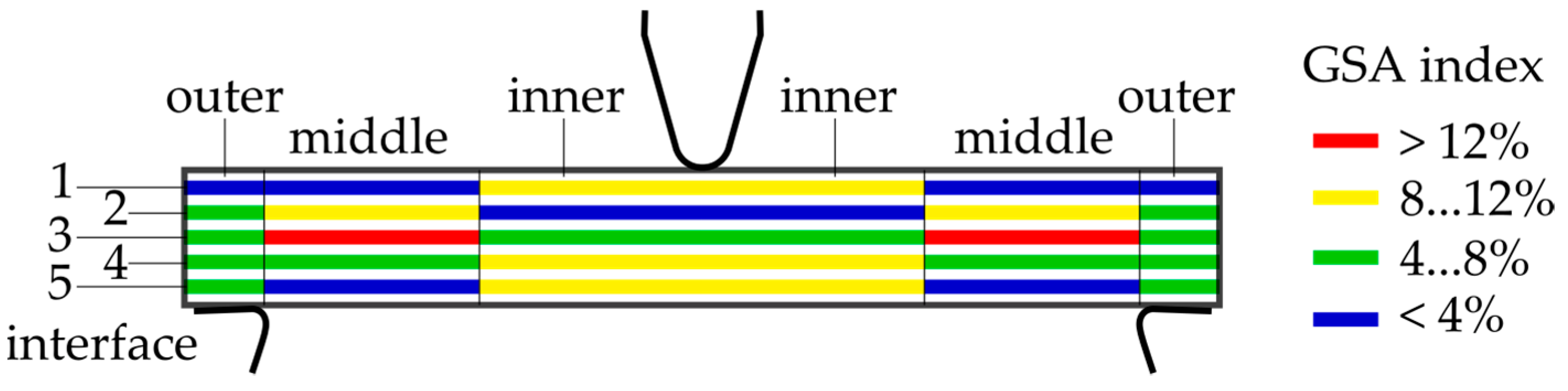
. The sum of the indexes is normalised to 1.
Figure 11 shows the GSA index of the 15 interfaces. This shows that interface 3 has the greatest influence on energy absorption. Interfaces 2 and 4 are of secondary importance, and interfaces 1 and 5 are almost negligible. The inner interfaces seem to have a slightly greater influence on the structural behaviour than the middle interfaces, with the exception of interface 3. The inner interfaces in interface 1 are important because of the bulging effect, which describes delamination initiation due to local buckling of the upper plies under the compressive load. The outer interfaces have no significant influence on the structural behaviour.
It can therefore be assumed that the out-of-plane regions subjected to shear stress are especially responsible for the delamination initiation and propagation because the three-point bending induces shear stress and it is not an edge effect. Otherwise, the outer interface design would have a greater GSA index.

 ,
, 


