
Mission Performance Analysis of Hybrid-Electric Regional Aircraft


Abstract
:1. Introduction
2. Hybrid-Electric Aircraft Design
2.1. Hybrid-Electric Aircraft Requirements
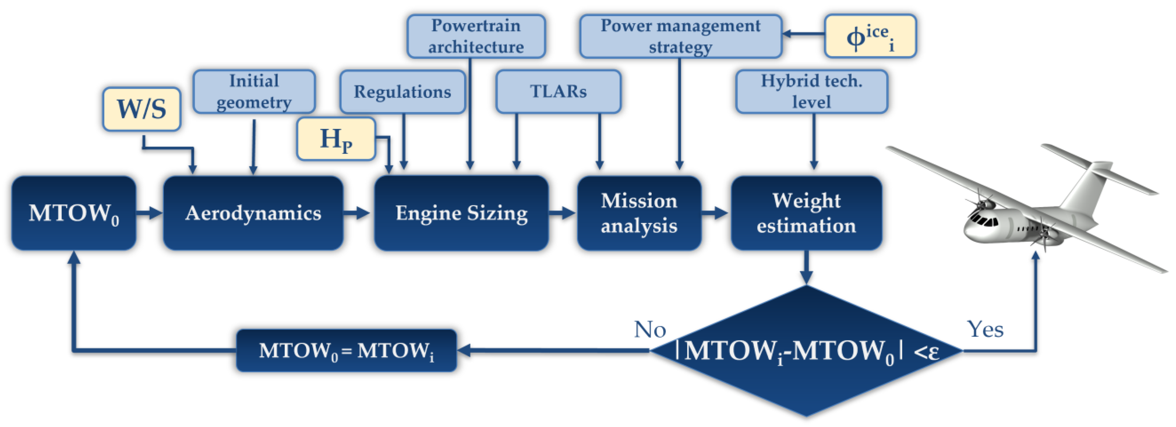
2.2. Conceptual Design Methodology
2.3. Mission Simulation and Performance Analysis
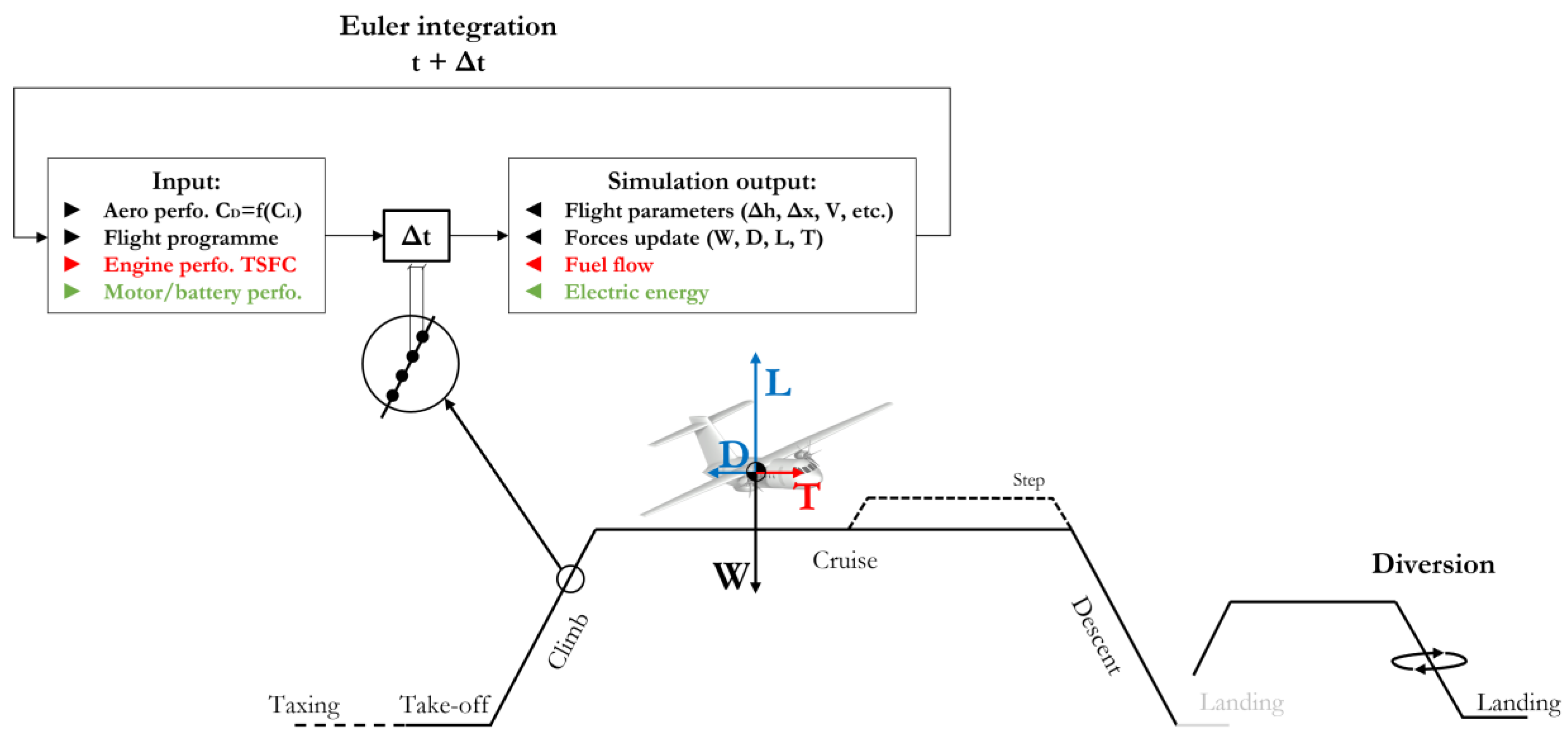
2.3.1. Overview
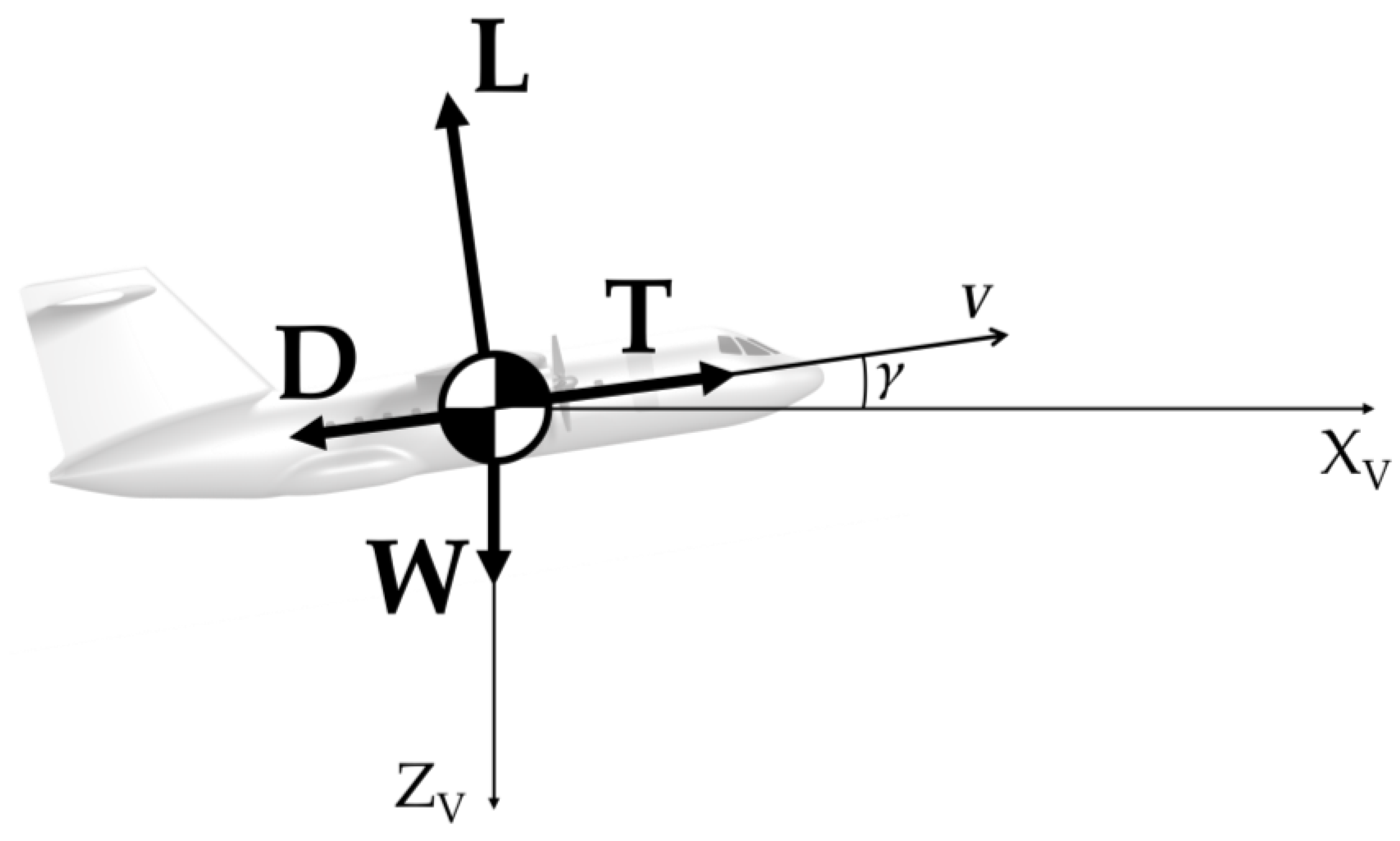
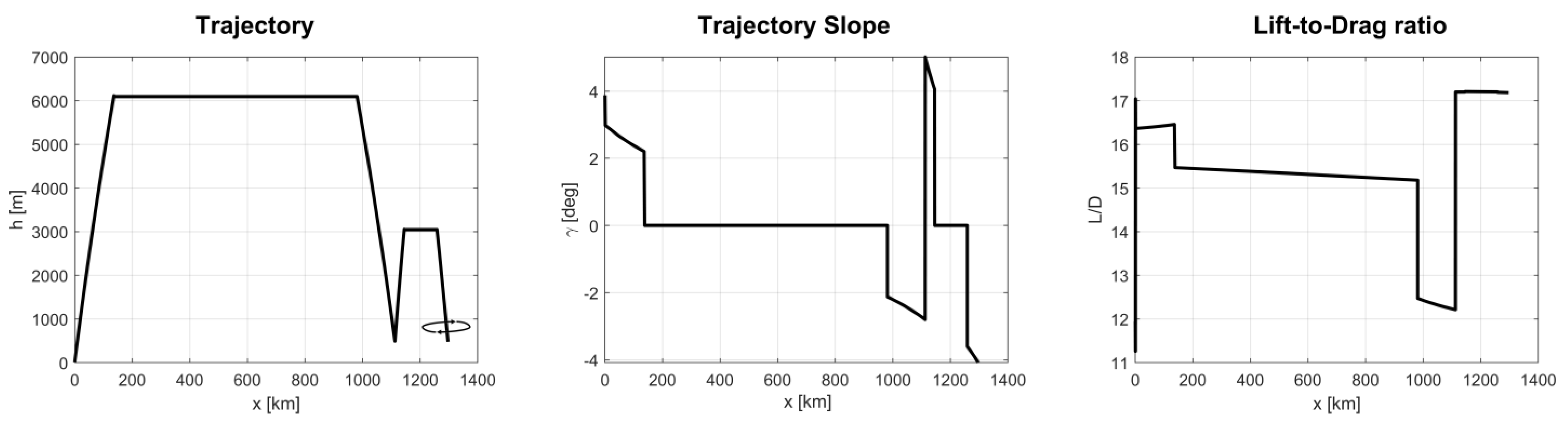
2.3.2. Mission Simulation: Aeromechanics
- Taxi-out: ground manoeuvring with constant power supply for 240 s;
- Take-off: full-power supply for 45 s;
- Climb: constant indicated air speed (IAS) and rate of climb (RoC);
- Cruise: constant speed and altitude;
- Descent: constant indicated air speed (IAS) and rate of descent (RoD);
- Loiter: 30 min of level flight at maximum L/D;
- Approach: constant RoD;
- Landing: neglected;
- Taxi-in: ground manoeuvring with constant power supply for 240 s.
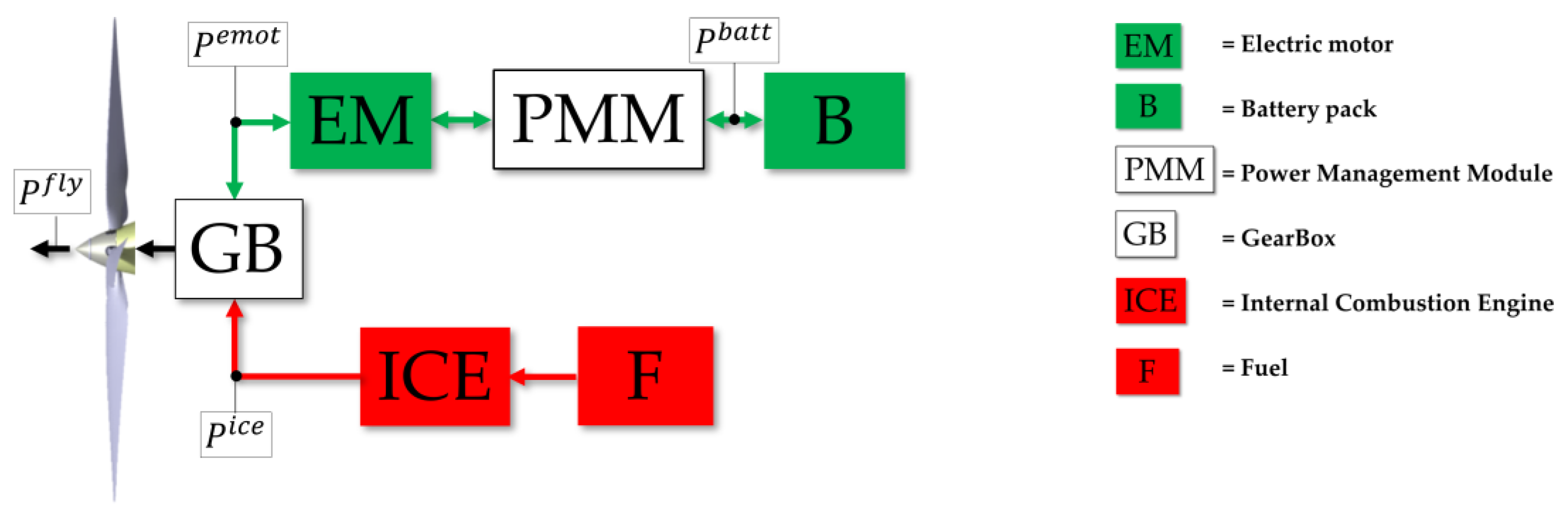
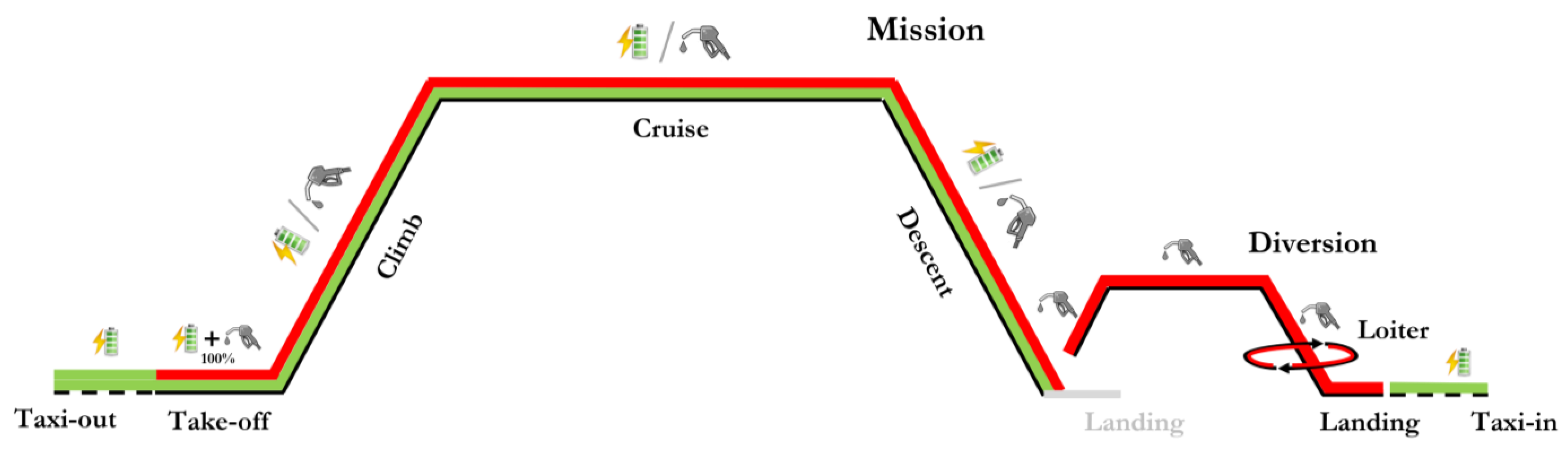
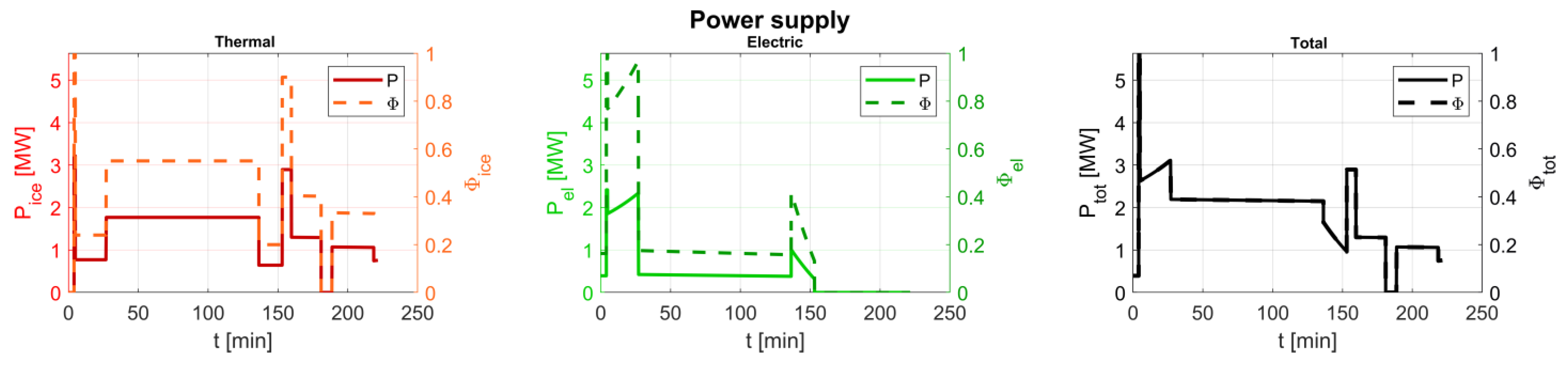
2.3.3. Mission Simulation: Power Supply
- Taxi-out/Taxi-in: taxiing is performed with only electrical power supply, in order to suppress all air-polluting emissions on the ground;
- Take-off: all the available power on board, both electrical and thermal, is supplied;
- Climb, Cruise, Descent: for each phase, electrical and thermal power are supplied in different quotas to match the total power required for the flight, according to a strategy set by the designer/operator.
3. Hybrid-Electric Aircraft Performance Analysis
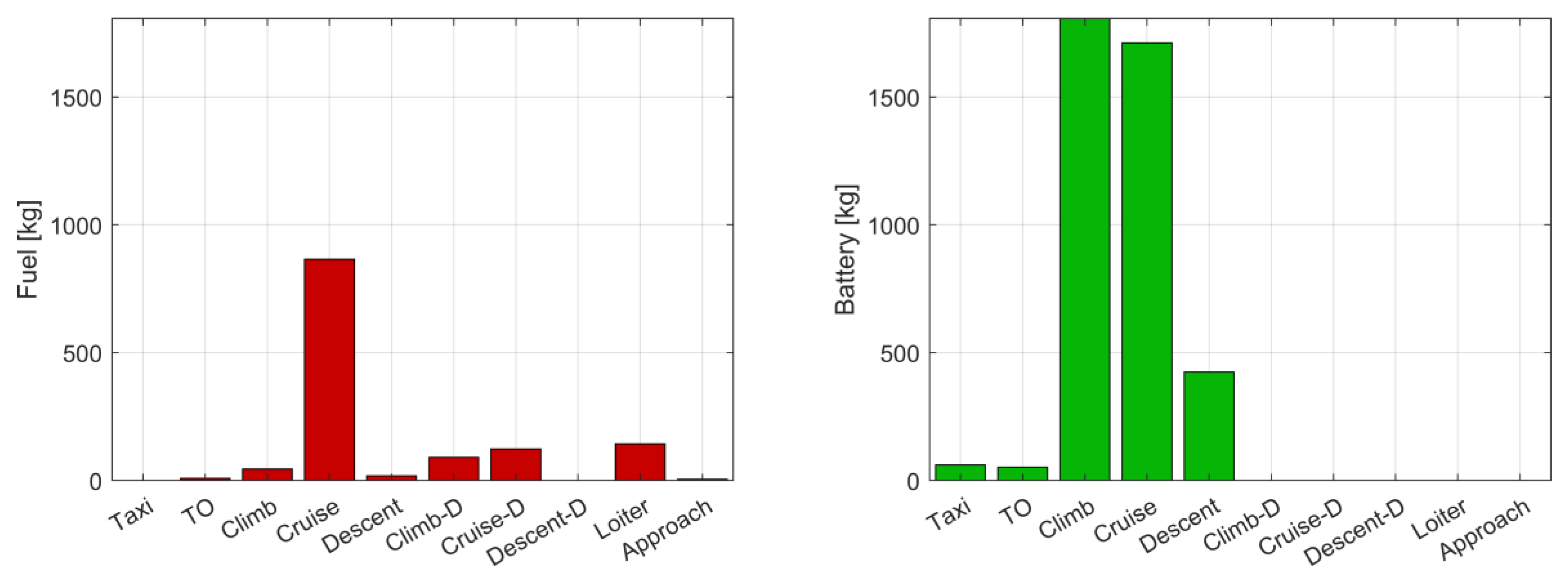
3.1. Analysis of the Design Mission Performance
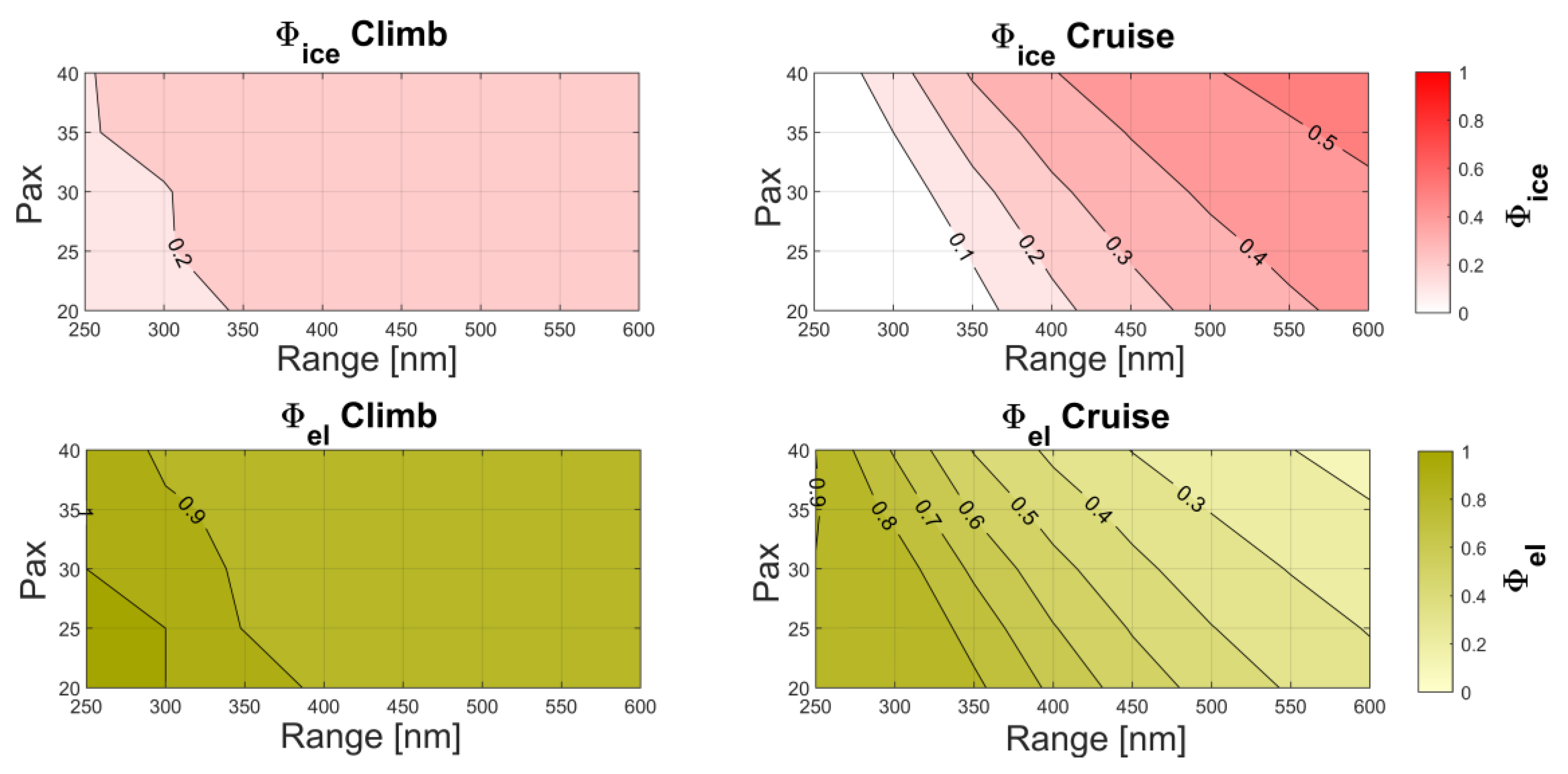
3.2. Analysis of the Off-Design Mission Performance
4. Beyond the Design Point: Payload–Range Diagram Analysis
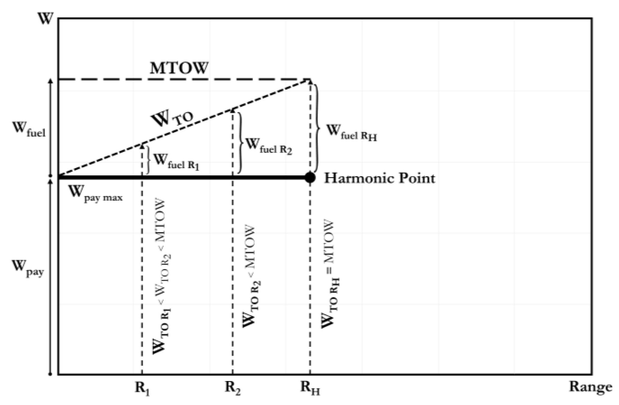
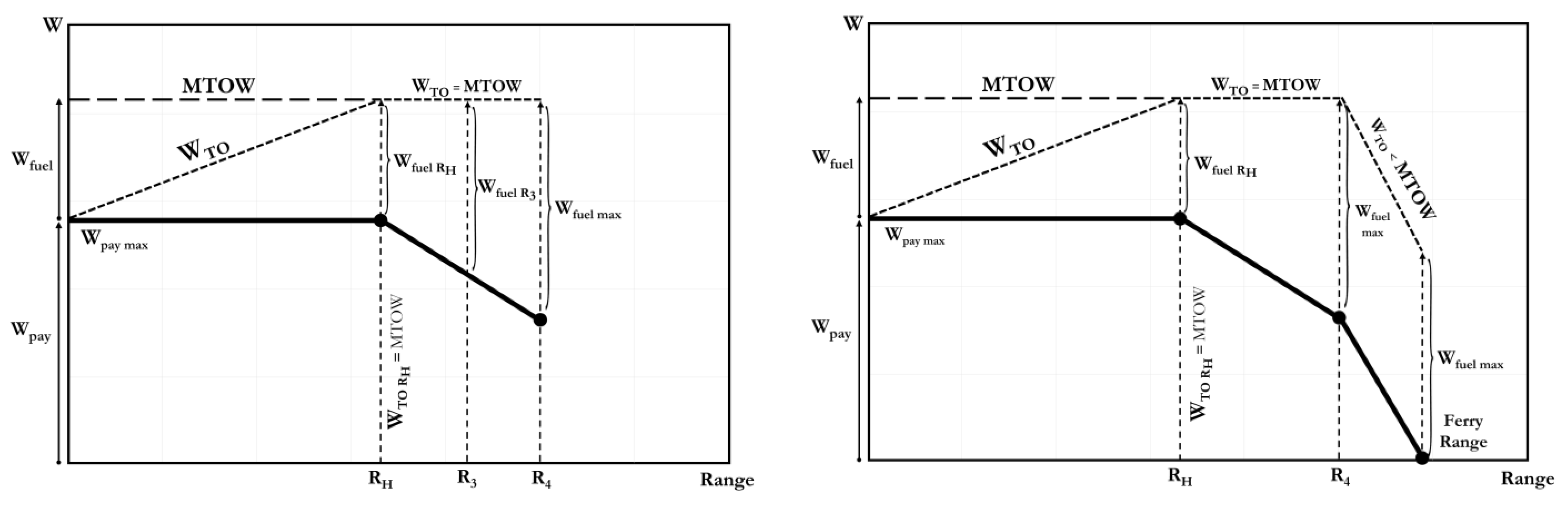
4.1. Payload–Range Diagram for Aircraft with Thermal Propulsion
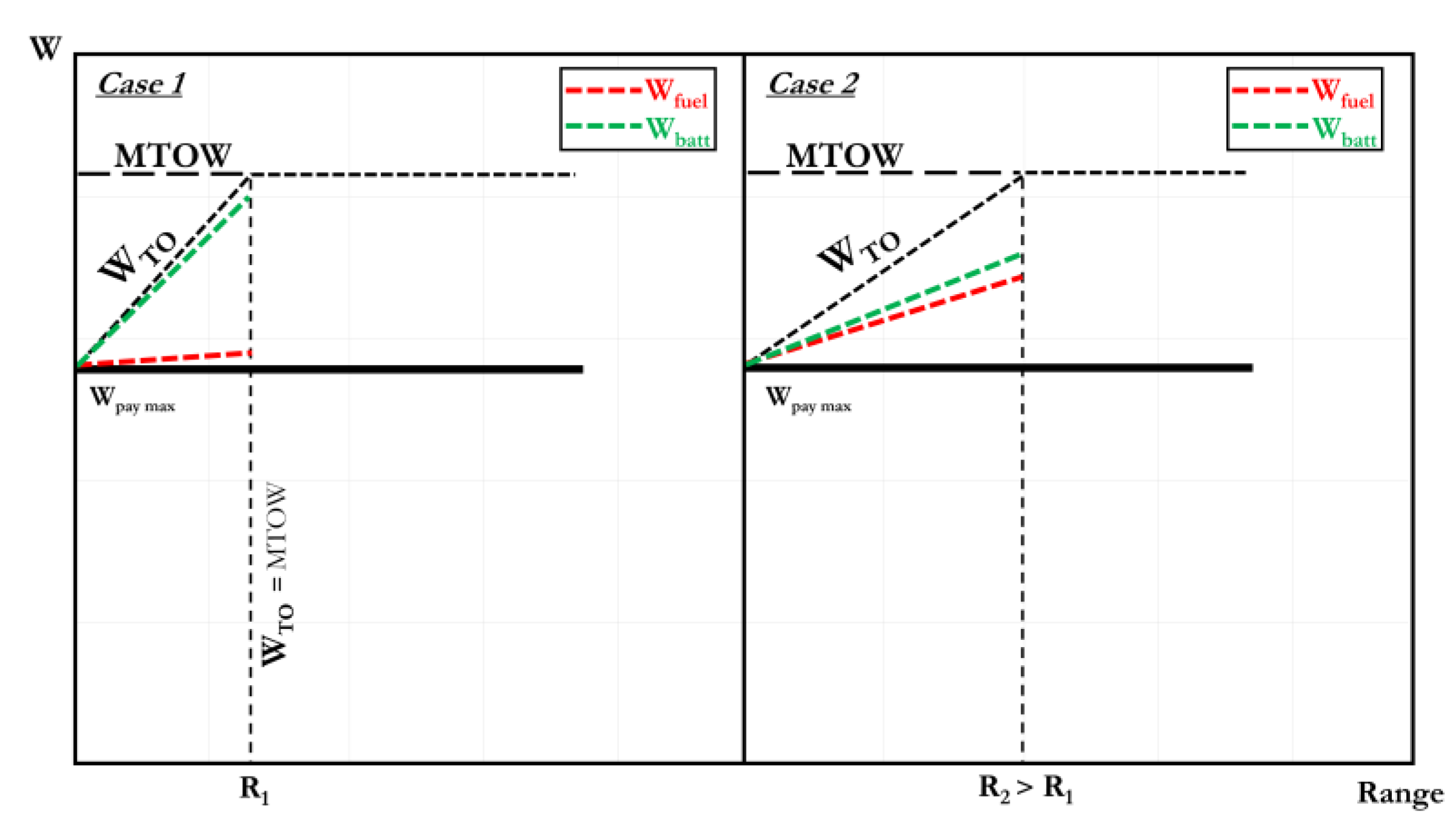
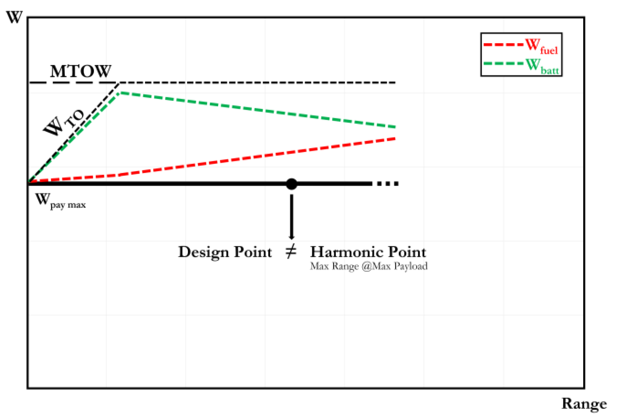
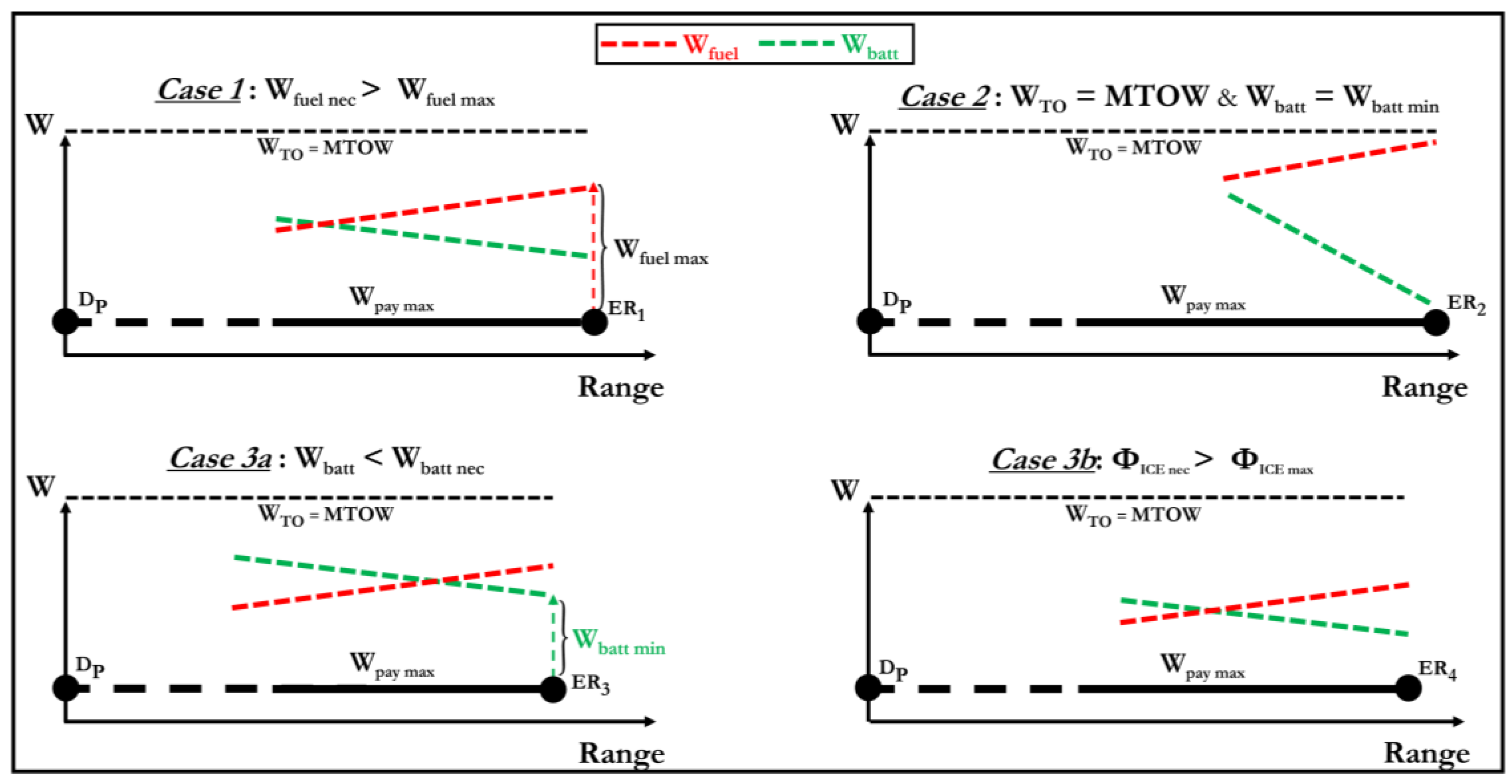
4.2. Payload–Range Diagram for Aircraft with Hybrid-Electric Propulsion
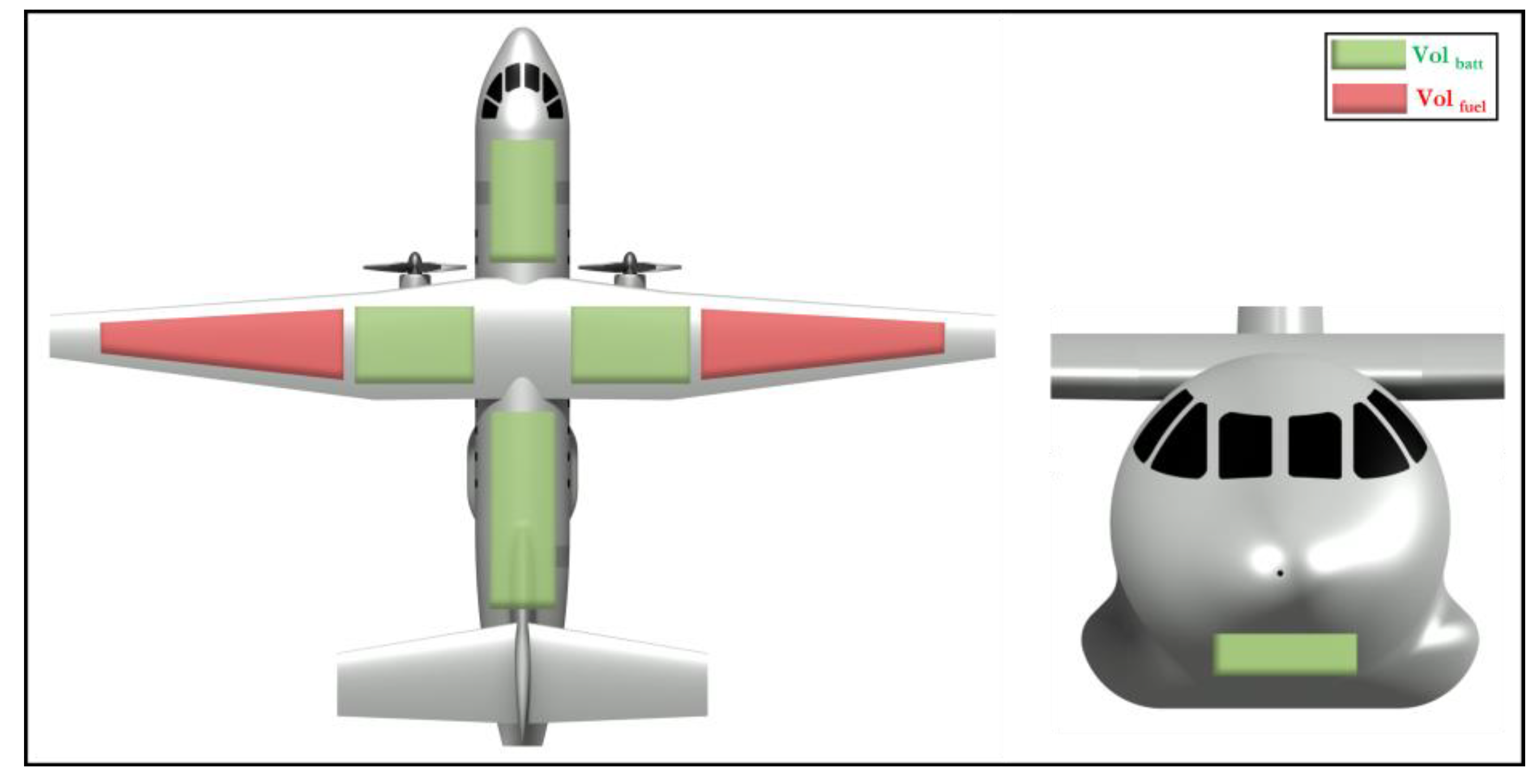
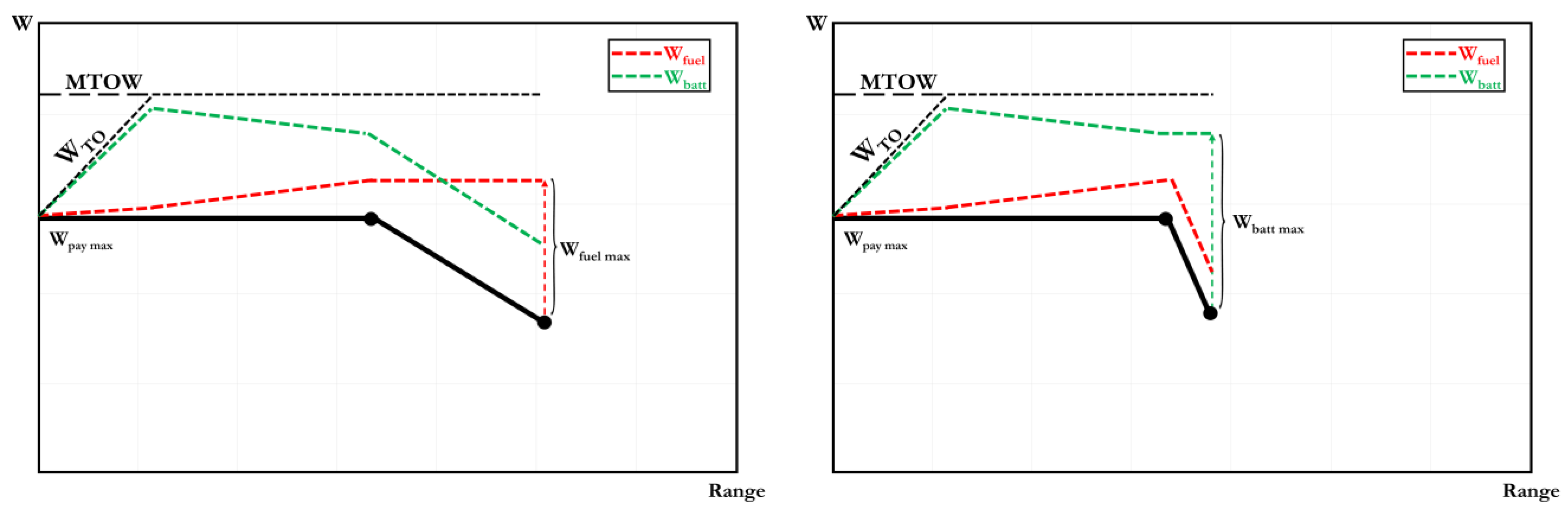
- Case 1: the extended range is limited by the saturation of the maximum volume available for fuel; this depends on the design of the aircraft, in particular on the allocation of internal volumes for fuel and/or batteries.
- Case 2: the extended range is limited because the MTOW is reached, no further battery–fuel mass swap is possible, hence it is necessary to start reducing the payload.
- Case 3: the extended range is limited by the lack of available energy or power, which depends on the sizing of the propulsion system and in particular on the hybridisation factor. Two subcases are possible:
- ◯
- 3a: electrical energy is not sufficient to accomplish one or more stages of the mission;
- ◯
- 3b: the power provided by the thermal engine is not sufficient to accomplish one or more mission stages.
5. Conclusions
Author Contributions
Funding
Data Availability Statement
Conflicts of Interest
References
- Lee, D.S.; Fahey, D.W.; Forster, P.M.; Newton, P.J.; Wit, R.C.N.; Lim, L.L.; Owen, B.; Sausen, R. Aviation and global climate change in the 21st century. Atmos. Environ. 2009, 43, 3520–3537. [Google Scholar] [CrossRef] [PubMed] [Green Version]
- Parker, R. From blue skies to green skies: Engine technology to reduce the climate-change impacts of aviation. Technol. Anal. Strat. Manag. 2009, 21, 61–78. [Google Scholar] [CrossRef]
- Brooker, P. Civil aircraft design priorities: Air quality? Climate change? Noise? Aeronaut. J. 2006, 110, 517–532. [Google Scholar] [CrossRef]
- European Commission. Reducing Emissions from Aviation; on-line documentation; European Commission: Brussels, Belgium, 2021; Available online: https://ec.europa.eu/clima/eu-action/transport-emissions/reducing-emissions-aviation_en (accessed on 15 January 2023).
- Abbas, A.; de Vicente, J.; Valero, E. Aerodynamic technologies to improve aircraft performance. Aerosp. Sci. Technol. 2013, 28, 100–132. [Google Scholar] [CrossRef]
- Cavallaro, R.; Demasi, L. Challenges, Ideas, and Innovations of Joined-Wing Configurations: A Concept from the Past, an Opportunity for the Future. Prog. Aerosp. Sci. 2016, 87, 1–93. [Google Scholar] [CrossRef]
- Bravo-Mosquera, P.D.; Catalano, F.M.; Zingg, D.W. Unconventional aircraft for civil aviation: A review of concepts and design methodologies. Prog. Aerosp. Sci. 2022, 131, 100813. [Google Scholar] [CrossRef]
- Okonkwo, P.; Smith, H. Review of evolving trends in blended wing body aircraft design. Prog. Aerosp. Sci. 2016, 82, 1–23. [Google Scholar] [CrossRef]
- Abu Salem, K.; Cipolla, V.; Palaia, G.; Binante, V.; Zanetti, D. A physics-based multidisciplinary approach for the preliminary design and performance analysis of a medium range aircraft with box-wing architecture. Aerospace 2021, 8, 292. [Google Scholar] [CrossRef]
- Bravo-Mosquera, P.D.; Cerón-Muñoz, H.D.; Catalano, F.M. Design, aerodynamic analysis and optimization of a next-generation commercial airliner. J. Braz. Soc. Mech. Sci. Eng. 2022, 44, 609. [Google Scholar] [CrossRef]
- Khandelwal, B.; Karakurt, A.; Sekaran, P.R.; Sethi, V.; Singh, R. Hydrogen powered aircraft: The future of air transport. Prog. Aerosp. Sci. 2013, 60, 45–59. [Google Scholar] [CrossRef]
- Rao, A.G.; Yin, F.; Werij, H.G. Energy Transition in Aviation: The Role of Cryogenic Fuels. Aerospace 2020, 7, 181. [Google Scholar] [CrossRef]
- Chiaramonti, D. Sustainable Aviation Fuels: The challenge of decarbonization. Energy Procedia 2019, 158, 1202–1207. [Google Scholar] [CrossRef]
- Magrini, A.; Benini, E.; Yao, H.-D.; Postma, J.; Sheaf, C. A review of installation effects of ultra-high bypass ratio engines. Prog. Aerosp. Sci. 2020, 119, 100680. [Google Scholar] [CrossRef]
- Hendricks, E.; Tong, M. Performance and weight estimates for an advanced open rotor engine. In Proceedings of the 48th AIAA/ASME/SAE/ASEE Joint Propulsion Conference & Exhibit, Atlanta, GA, USA, 30 July–1 August 2012. [Google Scholar] [CrossRef] [Green Version]
- Brelje, B.J.; Martins, J.R. Electric, hybrid, and turboelectric fixed-wing aircraft: A review of concepts, models, and design approaches. Prog. Aerosp. Sci. 2018, 104, 1–19. [Google Scholar] [CrossRef]
- Sahoo, S.; Zhao, X.; Kyprianidis, K. A Review of Concepts, Benefits, and Challenges for Future Electrical Propulsion-Based Aircraft. Aerospace 2020, 7, 44. [Google Scholar] [CrossRef] [Green Version]
- Schäfer, A.W.; Barrett, S.R.H.; Doyme, K.; Dray, L.M.; Gnadt, A.R.; Self, R.; O’Sullivan, A.; Synodinos, A.P.; Torija, A.J. Technological, economic and environmental prospects of all-electric aircraft. Nat. Energy 2019, 4, 160–166. [Google Scholar] [CrossRef] [Green Version]
- Geiß, I.; Voit-Nitschmann, R. Sizing of the energy storage system of hybrid-electric aircraft in general aviation. CEAS Aeronaut. J. 2017, 8, 53–65. [Google Scholar] [CrossRef]
- Riboldi, C.; Gualdoni, F. An integrated approach to the preliminary weight sizing of small electric aircraft. Aerosp. Sci. Technol. 2016, 58, 134–149. [Google Scholar] [CrossRef]
- Hospodka, J.; Bínová, H.; Pleninger, S. Assessment of All-Electric General Aviation Aircraft. Energies 2020, 13, 6206. [Google Scholar] [CrossRef]
- Salucci, F.; Trainelli, L.; Bruglieri, M.; Riboldi, C.E.; Rolando, A.L.; García González, G. Capturing the Demand for an Electric-Powered Short-Haul Air Transportation Network. In Proceedings of the AIAA SciTech Forum, Nashville, TN, USA, 11–15 January 2021. [Google Scholar] [CrossRef]
- Orefice, F.; Marciello, V.; Nicolosi, F.; Zhang, Q.; Wortmann, G.; Menu, J.; Cusati, V. Design of Hybrid-Electric Small Air Transports. IOP Conf. Ser. Mater. Sci. Eng. 2022, 1226, 012075. [Google Scholar] [CrossRef]
- Orefice, F.; Nicolosi, F.; Della Vecchia, P.; Ciliberti, D. Aircraft conceptual design of commuter aircraft including distributed electric propulsion. In Proceedings of the AIAA Aviation Forum, Virtual, 15–19 June 2020. [Google Scholar] [CrossRef]
- Rolando, A.; Salucci, F.; Trainelli, L.; Riboldi, C.E.; Khan, Y.M. On the Design of an Electric-Powered Micro-Feeder Aircraft. In Proceedings of the 1st Aerospace Europe Conference (AEC), Bordeaux, France, 25–28 February 2020. [Google Scholar]
- Isikveren, A.T.; Fefermann, Y.; Maury, C.; Level, C.; Zarati, K.; Salanne, J.-P.; Pornet, C.; Thoraval, B. Pre-design of a commuter transport utilising Voltaic-Joule/Brayton motive power systems. Aeronaut. J. 2018, 122, 205–237. [Google Scholar] [CrossRef]
- Ciliberti, D.; Della Vecchia, P.; Memmolo, V.; Nicolosi, F.; Wortmann, G.; Ricci, F. The Enabling Technologies for a Quasi-Zero Emissions Commuter Aircraft. Aerospace 2022, 9, 319. [Google Scholar] [CrossRef]
- Donateo, T.; Ficarella, A. A Methodology for the Comparative Analysis of Hybrid Electric and All-Electric Power Systems for Urban Air Mobility. Energies 2022, 15, 638. [Google Scholar] [CrossRef]
- Bacchini, A.; Cestino, E. Electric VTOL Configurations Comparison. Aerospace 2019, 6, 26. [Google Scholar] [CrossRef] [Green Version]
- Palaia, G.; Abu Salem, K.; Cipolla, V.; Binante, V.; Zanetti, D. A Conceptual Design Methodology for e-VTOL Aircraft for Urban Air Mobility. Appl. Sci. 2021, 11, 10815. [Google Scholar] [CrossRef]
- Finger, D.F.; Götten, F.; Braun, C.; Bil, C. Initial sizing for a family of hybrid-electric VTOL general aviation aircraft. Deutsche Ges. Luft-Raumfahrt 2018. [Google Scholar] [CrossRef]
- Graver, B.; Zhang, K.; Rutherford, D. CO2 Emissions From Commercial Aviation; ICCT, The International Council on Clean Transportation: Washington, DC, USA, 2018; Available online: https://theicct.org/publications/co2-emissions-commercial-aviation-2018 (accessed on 15 January 2023).
- Pornet, C.; Gologan, C.; Vratny, P.C.; Seitz, A.; Schmitz, O.; Isikveren, A.T.; Hornung, M. Methodology for Sizing and Performance Assessment of Hybrid Energy Aircraft. J. Aircr. 2015, 52, 341–352. [Google Scholar] [CrossRef]
- Pornet, C.; Isikveren, A. Conceptual design of hybrid-electric transport aircraft. Prog. Aerosp. Sci. 2015, 79, 114–135. [Google Scholar] [CrossRef]
- Ang, A.W.X.; Rao, A.G.; Kanakis, T.; Lammen, W. Performance analysis of an electrically assisted propulsion system for a short-range civil aircraft. Proc. Inst. Mech. Eng. Part G J. Aerosp. Eng. 2018, 233, 1490–1502. [Google Scholar] [CrossRef] [Green Version]
- Gnadt, A.R.; Speth, R.L.; Sabnis, J.S.; Barrett, S.R. Technical and environmental assessment of all-electric 180-passenger commercial aircraft. Prog. Aerosp. Sci. 2018, 105, 1–30. [Google Scholar] [CrossRef] [Green Version]
- Sgueglia, A.; Schmollgruber, P.; Bartoli, N.; Benard, E.; Morlier, J.; Jasa, J.; Martins, J.R.R.A.; Hwang, J.T.; Gray, J.S. Multidisciplinary Design Optimization Framework with Coupled Derivative Computation for Hybrid Aircraft. J. Aircr. 2020, 57, 715–729. [Google Scholar] [CrossRef]
- de Vries, R.; Brown, M.; Vos, R. Preliminary Sizing Method for Hybrid-Electric Distributed-Propulsion Aircraft. J. Aircr. 2019, 56, 2172–2188. [Google Scholar] [CrossRef]
- Karpuk, S.; Elham, A. Influence of Novel Airframe Technologies on the Feasibility of Fully-Electric Regional Aviation. Aerospace 2021, 8, 163. [Google Scholar] [CrossRef]
- Voskuijl, M.; van Bogaert, J.; Rao, A.G. Analysis and design of hybrid electric regional turboprop aircraft. CEAS Aeronaut. J. 2017, 9, 15–25. [Google Scholar] [CrossRef] [Green Version]
- Finger, F.; Braun, C.; Bil, C. Comparative Assessment of Parallel-Hybrid-Electric Propulsion Systems for Four Different Aircraft. J. Aircr. 2020, 57, 843–853. [Google Scholar] [CrossRef]
- Hoelzen, J.; Liu, Y.; Bensmann, B.; Winnefeld, C.; Elham, A.; Friedrichs, J.; Hanke-Rauschenbach, R. Conceptual Design of Operation Strategies for Hybrid Electric Aircraft. Energies 2018, 11, 217. [Google Scholar] [CrossRef] [Green Version]
- Masson, P.J.; Brown, G.V.; Soban, D.S.; Luongo, C.A. HTS machines as enabling technology for all-electric airborne vehicles. Supercond. Sci. Technol. 2007, 20, 748–756. [Google Scholar] [CrossRef]
- Ganev, E. Selecting the Best Electric Machines for Electrical Power-Generation Systems: High-performance solutions for aerospace More electric architectures. IEEE Electrif. Mag. 2014, 2, 13–22. [Google Scholar] [CrossRef]
- Bugga, R.; Krause, C.; Smart, M.; West, W.; Brandon, E. Battery for electric aviation. In Proceedings of the NAATBatt Annual Meeting & Conference, Pasadena, CA, USA, 10–13 February 2020; Available online: https://trs.jpl.nasa.gov/handle/2014/52585 (accessed on 15 January 2023).
- Adu-Gyamfi, B.A.; Good, C. Electric aviation: A review of concepts and enabling technologies. Transp. Eng. 2022, 9, 100134. [Google Scholar] [CrossRef]
- Vratny, P.; Gologan, C.; Pornet, C.; Isikveren, A.; Hornung, M. Battery Pack Modeling Methods for Universally-Electric Aircraft. In Proceedings of the 4th CEAS Air & Space Conference, Linköping, Sweden, 17–19 September 2013. [Google Scholar]
- Vegh, J.M.; MacDonald, T.; Wendorff, A.; Alonso, J.J. Sizing Methods for Aircraft of Variable Propulsion System Complexity. In Proceedings of the 55th AIAA Aerospace Sciences Meeting, Grapevine, TX, USA, 9–13 January 2017. [Google Scholar] [CrossRef] [Green Version]
- Ugwueze, O.; Statheros, T.; Horri, N.; Innocente, M.; Bromfield, M. Investigation of a Mission-based Sizing Method for Electric VTOL Aircraft Preliminary Design. In Proceedings of the AIAA SciTech Forum, San Diego, CA, USA, 3–7 January 2022. [Google Scholar] [CrossRef]
- Eisenhut, D.; Moebs, N.; Windels, E.; Bergmann, D.; Geiß, I.; Reis, R.; Strohmayer, A. Aircraft Requirements for Sustainable Regional Aviation. Aerospace 2021, 8, 61. [Google Scholar] [CrossRef]
- Palaia, G.; Zanetti, D.; Abu Salem, K.; Cipolla, V.; Binante, V. THEA-CODE: A design tool for the conceptual design of hybrid-electric aircraft with conventional or unconventional airframe configurations. Mech. Ind. 2021, 22, 19. [Google Scholar] [CrossRef]
- Palaia, G. Design and Performance Assessment Methodologies for Box-Wing Hybrid-Electric Aircraft from Urban to Regional Transport Applications. Ph.D. Thesis, University of Pisa, Pisa, Italy, 2022. to be published. [Google Scholar]
- Drela, M.; Youngren, H. AVL 3.36 User Primer, Online Software Manual. 2017. Available online: https://perma.cc/R35R-W29F (accessed on 15 January 2023).
- Raymer, P. Aircraft Design: A Conceptual Approach; AIAA Education Series; American Institute of Aeronautics and Astronautics, Inc.: Washington, DC, USA, 1992; ISBN 0-930403-51-7. [Google Scholar]
- Mattingly, J.D.; Heiser, W.H.; Daley, D.H. Aircraft Engine Design, 3rd ed.; American Institute of Aeronautics and Astronautics: Washington, DC, USA, 2018; Available online: https://arc.aiaa.org/doi/book/10.2514/4.105173 (accessed on 15 January 2023).
- Sforza, P.M. Commercial Airplane Design Principles, 1st ed.; Butterworth–Heinemann: Oxford, UK, 2014; Available online: https://www.sciencedirect.com/book/9780124199538/commercial-airplane-design-principles (accessed on 15 February 2023).
- Federal Aviation Administration, FAR 25, Airworthiness Standards: Transport Category Airplanes, 1980.
- Wells, D.P.; Horvath, B.L.; McCullers, L.A. The Flight Optimization System Weights Estimation Method. NASA Tech. Rep. 2017. Available online: https://ntrs.nasa.gov/citations/20170005851 (accessed on 15 January 2023).
- Cipolla, V.; Abu Salem, K.; Palaia, G.; Binante, V.; Zanetti, D. A DoE-based approach for the implementation of structural surrogate models in the early stage design of box-wing aircraft. Aerosp. Sci. Technol. 2021, 117, 106968. [Google Scholar] [CrossRef]
- Dever, T.P.; Duffy, K.P.; Provenza, A.J.; Loyselle, P.L.; Choi, B.B.; Morrison, C.R.; Lowe, A.M. Assessment of Technologies for Noncryogenic Hybrid Electric Propulsion. Rep. NASA 2015, TP-2015-216588. [Google Scholar]
- Pornet, C.; Kaiser, S.; Gologan, C. Cost-based flight technique optimization for hybrid energy aircraft. Aircr. Eng. Aerosp. Technol. 2014, 86, 591–598. [Google Scholar] [CrossRef]
- Casarosa, C. Meccanica del Volo; Pisa University Press: Pisa, Italy, 2013; ISBN 978-8867410163. [Google Scholar]
- Garza, F.; Morelli, E. A Collection of Nonlinear Aircraft Simulations in MatLab. Tech. Memo 2003. NASA/TM-2003-212145. Available online: https://ntrs.nasa.gov/citations/20030013626 (accessed on 15 January 2023).
- Stevens, B.; Lewis, F.; Johnson, E. Aircraft Control and Simulation: Dynamics, Controls Design, and Autonomous Systems; John Wiley & Sons: Hoboken, NJ, USA, 2015; ISBN 978-1-118-87098-3. [Google Scholar]
- Yu, Y.; Yao, H.; Liu, Y. Aircraft dynamics simulation using a novel physics-based learning method. Aerosp. Sci. Technol. 2019, 87, 254–264. [Google Scholar] [CrossRef]
- Howe, R. An improved numerical integration method for flight simulation. In Proceedings of the AIAA Flight Simulation Technologies Conference and Exhibit, Boston, MA, USA, 14–16 August 1989. [Google Scholar] [CrossRef] [Green Version]
- Torres, S. Evaluation of Numerical Methods for Aircraft Trajectory Computation. In Proceedings of the IEEE/AIAA 37th Digital Avionics Systems Conference (DASC), London, UK, 23–27 September 2018; pp. 1–10. [Google Scholar] [CrossRef]
- De Marco, A.; Trifari, V.; Nicolosi, F.; Ruocco, M. A Simulation-Based Performance Analysis Tool for Aircraft Design Workflows. Aerospace 2020, 7, 155. [Google Scholar] [CrossRef]
- Trifari, V.; Ruocco, M.; Cusati, V.; Nicolosi, F.; De Marco, A. Java framework for parametric aircraft design—Ground performance. Aircr. Eng. Aerosp. Technol. 2017, 89, 599–608. [Google Scholar] [CrossRef] [Green Version]
- Nicolosi, F.; De Marco, A.; Attanasio, L.; Della Vecchia, P. Development of a Java-based framework for aircraft preliminary design and optimization. J. Aerosp. Inf. Syst. 2016, 13, 234–242. [Google Scholar] [CrossRef] [Green Version]
- De Marco, A.; Cusati, V.; Trifari, V.; Ruocco, M.; Nicolosi, F.; Della Vecchia, P. A java toolchain of programs for aircraft design. In Proceedings of the 6th CEAS Conference, Bucharest, Romania, 16–20 October 2017; Available online: https://www.iris.unina.it/retrieve/handle/11588/696606/156026/CEAS2017_Paper_ID214.pdf (accessed on 15 February 2023).
- De Marco, A.; Di Stasio, M.; Della Vecchia, P.; Trifari, V.; Nicolosi, F. Automatic modeling of aircraft external geometries for preliminary design workflows. Aerosp. Sci. Technol. 2020, 98, 105667. [Google Scholar] [CrossRef]
- Abu Salem, K.; Palaia, G.; Bianchi, M.; Zanetti, D.; Cipolla, V.; Binante, V. Preliminary Take-Off Analysis and Simulation of PrandtlPlane Commercial Aircraft. Aerotec. Missili Spaz. 2020, 99, 203–216. [Google Scholar] [CrossRef]
- de Wringer, S.; Varriale, C.; Oliviero, F. A Generalized Approach to Operational, Globally Optimal Aircraft Mission Performance Evaluation, with Application to Direct Lift Control. Aerospace 2020, 7, 134. [Google Scholar] [CrossRef]
- Kim, D.; Seth, A.; Liem, R.P. Data-enhanced dynamic flight simulations for flight performance analysis. Aerosp. Sci. Technol. 2022, 121, 107357. [Google Scholar] [CrossRef]
- Yanto, J.; Liem, R.P. Aircraft fuel burn performance study: A data-enhanced modeling approach. Transp. Res. Part D Transp. Environ. 2018, 65, 574–595. [Google Scholar] [CrossRef]
- Schmollgruber, P. Enhancement of the Conceptual Aircraft Design Process through Certification Constraints Management and Full Mission Simulations. Ph.D. Thesis, Doctorat de l’Université de Toulouse délivré par l’Institut Supérieur de l’Aéronautique et de l’Espace, ISAE, Toulouse, France, 2018. Available online: https://hal.science/tel-02146110/ (accessed on 15 February 2023).
- Schulz, S.; Ossmann, D.; Milz, D.; Kier, T.; Looye, G. Aircraft Mission Simulation Framework for Loads Analysis. In Proceedings of the AIAA Scitech Forum, Orlando, FL, USA, 6–10 January 2020. [Google Scholar] [CrossRef]
- Gong, A.; Palmer, J.L.; Brian, G.; Harvey, J.R.; Verstraete, D. Performance of a hybrid, fuel-cell-based power system during simulated small unmanned aircraft missions. Int. J. Hydrogen Energy 2016, 41, 11418–11426. [Google Scholar] [CrossRef]
- Liscouët-Hanke, S.; Pufe, S.; Maré, J.-C. A simulation framework for aircraft power management. Proc. Inst. Mech. Eng. Part G J. Aerosp. Eng. 2008, 222, 749–756. [Google Scholar] [CrossRef]
- Liscouët-Hanke, S.; Maré, J.-C.; Pufe, S. Simulation framework for aircraft power system architecting. J. Aircr. 2009, 46, 1375–1380. [Google Scholar] [CrossRef]
- Valdivia-Guerrero, V.; Foley, R.; Riverso, S.; Govindaraju, P.; Elsheikh, A.; Mangeruca, L.; Burgio, G.; Ferrari, A.; Gottschall, M.; Blochwitz, T.; et al. Modelling and Simulation Tools for Systems Integration on Aircraft. SAE Tech. Pap. 2016. [Google Scholar] [CrossRef]
- Abu Salem, K.; Giuseppe, P.; Vittorio, C.; Vincenzo, B.; Davide, Z.; Mario, C. Tools and methodologies for box-wing aircraft conceptual aerodynamic design and aeromechanic analysis. Mech. Ind. 2021, 22, 39. [Google Scholar] [CrossRef]
- Hanlon, P. Global Airlines. Competition in a Transnational Industry, 3rd ed.; Routledge: New York, NY, USA, 2007. [Google Scholar] [CrossRef]
- Husemann, M.; Schäfer, K.; Stumpf, E. Flexibility within flight operations as an evaluation criterion for preliminary aircraft design. J. Air Transp. Manag. 2018, 71, 201–214. [Google Scholar] [CrossRef]
- Torenbeek, E. Advanced Aircraft Design: Conceptual Design, Analysis and Optimization of Subsonic Civil Airplanes; John Wiley & Sons: Hoboken, NJ, USA, 2013. [Google Scholar]


| TLARs | |
|---|---|
| Number of seats | 40 |
| Cruise Mach | 0.4 |
| Cruise altitude | 20,000 ft |
| Design mission range | 600 nm |
| Balanced field length | 1100 m |
| Landing distance available | 1100 m |
| Mission | Diversion | |
|---|---|---|
| Climb | IAS = 170 kt RoC = 900 ft/min | IAS = 150 kt RoC = 600 ft/min |
| Cruise | Mach = 0.4 h = 6100 m | Mach = 0.27 h = 3050 m |
| Descent | IAS = 220 kt RoD = −1100 ft/min | IAS = 150 kt RoD = −1100 ft/min |
| Thermal Power Fraction | Electric Power Fraction | ||
|---|---|---|---|
| Mission | Taxi-out/in | (t) = 0 | (t) = 0.07 |
| Take-off | (t) = 1 | (t) = 1 | |
| Climb | (t) = const. = | (t) = f() | |
| Cruise | (t) = const. = | (t) = f() | |
| Descent | (t) = const. = | (t) = f() | |
| Diversion | Climbdiv | (t) = | (t) = 0 |
| Cruisediv | (t) = | (t) = 0 | |
| Descentdiv | (t) = | (t) = 0 | |
| Number of Passengers | 40 |
| Design range | 600 nm |
| MTOW | 22,935 kg |
| OEW | 17,879 kg |
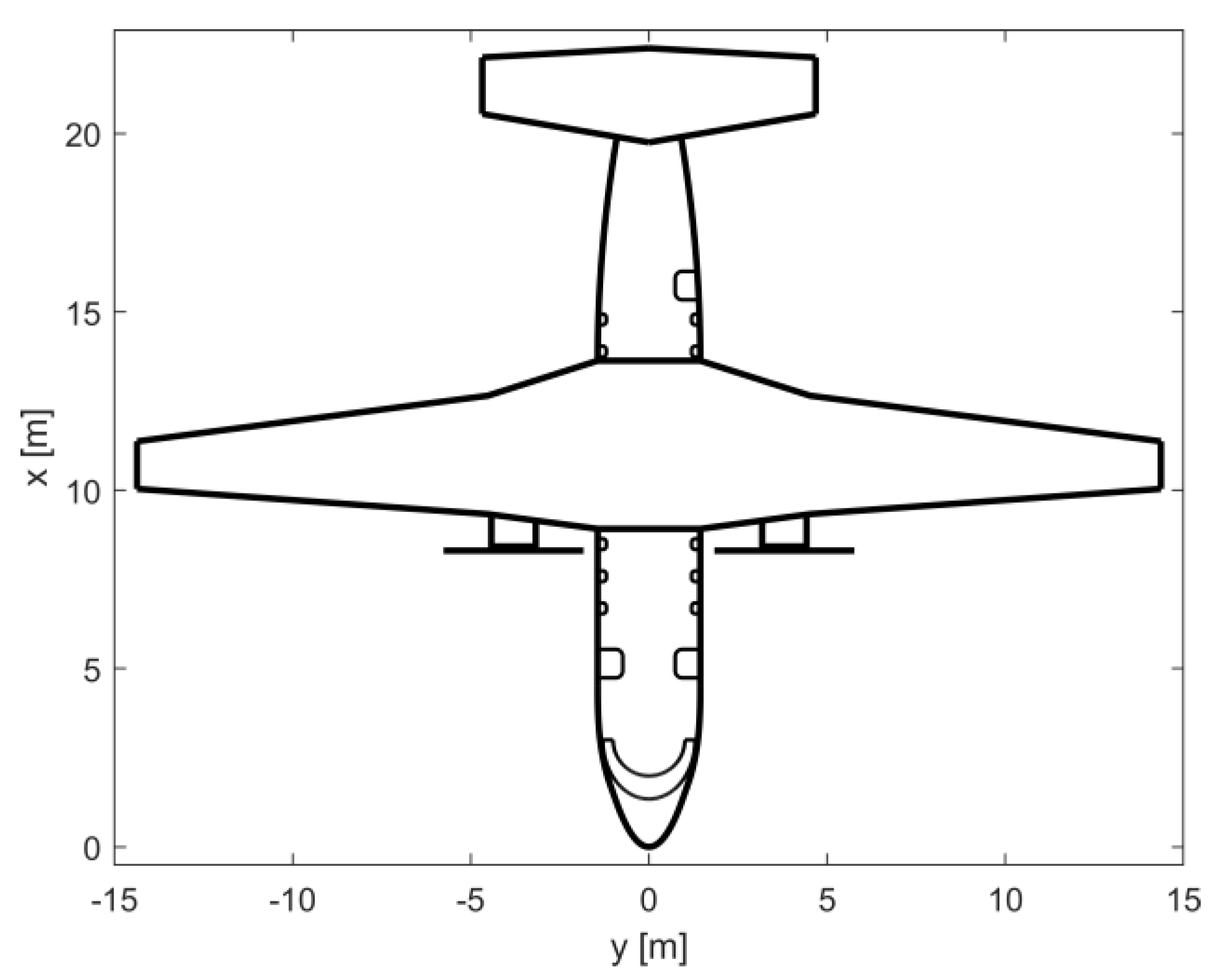
| Wing surface | 70.6 m2 |
| Wingspan | 28.7 m |
| Fuselage length | 21.9 m |
| Fuselage diameter | 2.88 m |
| Installed thermal power | 3.21 MW |
| Installed electric power | 2.49 MW |
| HP | 0.43 |
| Block fuel mass | 937 kg |
| Battery mass | 4054 kg |
| Design Point Features | Φice Limited | Swap Limited |
|---|---|---|
| HP | 0.43 | 0.27 |
| 0.28 | 0.37 | |
| 0.55 | 0.33 | |
| 0.20 | 0.53 | |
| MTOW | 22,935 kg | 22,960 kg |
| Installed thermal power | 3.21 MW | 4.39 MW |
| Installed electric power | 2.49 MW | 1.67 MW |
| Block fuel mass | 937 kg | 1041 kg |
| Battery mass | 4054 kg | 4065 kg |
Disclaimer/Publisher’s Note: The statements, opinions and data contained in all publications are solely those of the individual author(s) and contributor(s) and not of MDPI and/or the editor(s). MDPI and/or the editor(s) disclaim responsibility for any injury to people or property resulting from any ideas, methods, instructions or products referred to in the content. |
© 2023 by the authors. Licensee MDPI, Basel, Switzerland. This article is an open access article distributed under the terms and conditions of the Creative Commons Attribution (CC BY) license (https://creativecommons.org/licenses/by/4.0/).
Share and Cite
Palaia, G.; Abu Salem, K. Mission Performance Analysis of Hybrid-Electric Regional Aircraft. Aerospace 2023, 10, 246. https://doi.org/10.3390/aerospace10030246
Palaia G, Abu Salem K. Mission Performance Analysis of Hybrid-Electric Regional Aircraft. Aerospace. 2023; 10(3):246. https://doi.org/10.3390/aerospace10030246
Chicago/Turabian StylePalaia, Giuseppe, and Karim Abu Salem. 2023. "Mission Performance Analysis of Hybrid-Electric Regional Aircraft" Aerospace 10, no. 3: 246. https://doi.org/10.3390/aerospace10030246