Article

Aerodynamic Exploration of Corrugated Airfoil Based on NACA0030 for Inflatable Wing Structure

1
Beijing Zhonghangzhi Technology Co., Ltd., Beijing 100176, China
2
Institute of Optics and Electronics, Chinese Academy of Sciences, Chengdu 610209, China
3
Key Laboratory of Optical Engineering, Chinese Academy of Sciences, Chengdu 610209, China
*
Author to whom correspondence should be addressed.
Aerospace 2023, 10(2), 174; https://doi.org/10.3390/aerospace10020174
Submission received: 23 November 2022 / Revised: 7 February 2023 / Accepted: 8 February 2023 / Published: 13 February 2023
(This article belongs to the Special Issue Aerodynamics Design)

Abstract

:
The flow structures and surface pressure distributions on corrugated airfoils significantly differed from those on a conventional, smooth airfoil. An unsteady, two-dimensional computational simulation was carried out to investigate the flow behavior and associated aerodynamic performance of a group of corrugated airfoils with different levels of waviness at angles of attack from 0° to 20° with an interval of 2° at a low Reynolds number regime (Re = 1.2 × 10⁵) and were quantitatively compared with those of its smooth counterpart. Time-averaged aerodynamic coefficients demonstrated that the corrugated airfoils have a lower lift and higher drag because of trapped vortices in the corrugations. The pressure drag of the corrugated airfoils was greater than that of the smooth airfoil. In contrast, the viscous drag of the corrugated airfoils was smaller than that of the smooth airfoil because the recirculation generated in the corrugation could reduce the viscous drag. The averaged velocity gradient in the boundary layer showed that the thickness of the boundary layer increased significantly for the corrugated airfoils because of recirculating flow caused by the small-standing vortices trapped in the valley of corrugations. The smoother the corrugated surface, the closer the aerodynamic characteristics are to those of the smooth airfoil.

1. Introduction

With the continuous development and advancement of flexible materials, inflatable structures have recently attracted more and more attention in several fields, such as civil, naval, and aerospace engineering, and architecture, because of their lightweight and foldable structural features [1,2,3,4,5,6]. For example, different inflatable airplanes have been developed and tested in flight in the aeronautical field [3,4]. Furthermore, inflatable reentry vehicles have been extensively investigated in the astronautical field for deceleration and thermal protection in space explorations [5,6].
For an inflatable wing structure, the wing surface cannot be as smooth as a conventional rigid wing made of metal because of the structural load-bearing characteristics of flexible material. Thus, the surface of an inflatable wing is generally corrugated with a certain level of waviness as illustrated in Figure 1 [7,8]. Two typical structures of existing inflatable wings are shown in Figure 1. The first is a multi-beam wing and the second is a multi-tube wing. For the multi-beam wing, the upper and lower skins are constrained by the middle brace, so its integrity and load-bearing ability are strong. For the multi-tube wing, the inner structure contains several cylindrical inflatable tubes covered by an outer skin to main the geometric shape. Because the flexible structure comprises two layers, the wing has good sealing performance and strong damage resistance. It should be noted that both wings have corrugated surfaces because of the flexibility of the inflatable material.
Much like the corrugated wings manufactured for inflatable structures, some flying insects in nature, such as dragonflies and locusts, also have corrugated wings and not wings resembling smooth airfoil shapes [9,10]. Extensive experimental [9,10,11] and computational [12,13,14,15,16,17,18] investigations have been carried out to demonstrate that these corrugations significantly impact these insects’ aerodynamic performance.
Enlightened by observing these corrugated wing structures both in the engineering industry and in natural flyers, our research team has conducted some wind tunnel experiments and numerical simulations [7,8] to investigate the aerodynamic features of corrugated airfoils. Other institutions have also carried out experimental and computational works to explore the properties of non-smooth wings [9,10,11,12,13,14,15,16,17,18,19,20,21]. In our work in Ref [7], three-dimensional tandem-corrugated wings were tested computationally and experimentally, and final analyses demonstrated that at the computed range of the angle of attack, tandem-wing configuration could delay, or even suppress the trailing edge separation and then increase the aerodynamic efficiency significantly. Thus, it is concluded that the aerodynamic configuration is attractive and promising to use with UAVs or airships with flexible structures in the near future. Then, in our work in Ref [8], a group of wavy airfoils with different geometric shapes modified from NACA0030 were designed and then unsteady numerical simulations were carried out, in detail, to investigate the effect of waviness on the vortical structure in the flow field and overall aerodynamic characteristics in the low Reynolds number (Re = 1.2 × 10⁵) regime. The final results showed that compared with the smooth airfoil the separation flow for the wavy airfoil was more obvious, and the lift and its slope decreased significantly, although stalling was delayed. The smoother the wavy surface is, the closer the aerodynamic characteristics are to the smooth airfoil. Although the pressure drag of the wavy wing is greater than that of the smooth airfoil, the recirculation generated in the corrugation may reduce the viscous drag. However, because of the limitations of angle of attack, we have not yet investigated the aerodynamic results at angles of attack greater than 16°. In Ref [9,10,11,12,13,14,15,16,17,18,19,20,21], corrugated airfoils similar to dragonfly wings were studied. Because of the complicacy of the flow field, no agreement has been reached concerning the aerodynamic efficiency of the corrugations.
Although most existing literature focuses on the aerodynamic comparison between dragonfly-like corrugated wings and smooth wings or flat plates, no studies have been found that explore the effect of waviness, i.e., the level of corrugation, on the aerodynamic performance of inflatable corrugated wings, especially at angles of attack greater than 16°. Therefore, in this study, a group of corrugated airfoils with different levels of geometric waviness was designed based on NACA0030 to explore the aerodynamic effect of corrugation computationally. Furthermore, a detailed flow field was provided to quantify the evolution of the unsteady vortex and turbulent structures around the tested airfoils. In addition, since the corrugated airfoil and smooth-surfaced airfoil studied have precisely the same airfoil thickness, ambiguities due to the effects of airfoil thickness on the aerodynamic performances of the tested airfoils are eliminated, hopefully providing some technical support for the development of future inflatable airplanes.

2. Computational Method & Validation Case

Two-dimensional numerical studies have been carried out [22,23,24], and have found no intrinsic three-dimensional effects at low Reynolds numbers 105, further suggesting the suitability of two-dimensional studies. Only internal spars and the flexible outer skin of an aircraft with inflatable wing structures help maintain its aerodynamic shape and structural integrity after inflating. The stiffness and strength of inflatable structures mainly depend on the profile of the wing cross-section and the pressure difference between the internal air and the outer atmosphere. Therefore, a thick airfoil is an obvious design choice that provides structural integrity as well as loading space. However, compared with thin airfoils, the aerodynamic performance of a thick airfoil is less efficient for thick profiles. Therefore, earlier investigations [4,8] show that thicker airfoils are preferred for inflatable structures at a low Reynolds flow to compromise between aerodynamic performance and the benefits of an inflatable structure. Thus, the NACA0030 airfoil was selected as a baseline. To clarify the effect of these corrugations on aerodynamic characteristics, a group of corrugated airfoils with different levels of corrugation were constructed based on NACA0030 to quantitatively explore the flow features caused by these corrugations. As depicted in Figure 2, three corrugated airfoils, named Corrugated 14, Corrugated 21, and Corrugated 34, were designed. The number in each name indicates the inscribed circles for the profile, respectively. For example, for the Corrugated 14 airfoil, there are an entire 14 arcs that are tangential to the profile of baseline NACA0030 with their centers located on the chord to form the upper surface, and the lower surface was designed in the same way. Thus, the greater the number of arcs, the smoother the airfoil surface; it is also closer to the contour of the baseline NACA0030 airfoil. It can be seen in the subfigure that the Corrugated 34 airfoil nearly coincides with the baseline.
In this study, the numerical tool was determined to be accurate enough to capture the flow structures in the valley of corrugations or at the trailing edge at high angles of attack. Thus, ANSYS Fluent 19.5 was selected to solve the flow field, considering its accuracy and robustness. All the computational work was carried out in the Gekko Cluster in the High-Performance Computing Centre at Nanyang Technological University. First, two-dimensional, unsteady numerical simulations based on the Spalart–Allmaras (SA) one-equation turbulence model were conducted at angles of attack ranging from 0° to 20° with an interval of 2° for the baseline airfoil and three other levels of corrugated airfoils. For all the computations, results were assumed to converge when all the residuals appeared as less than 10−5.
Figure 3 shows the computational flow domain and boundary layer around these four airfoils. The chord length of each airfoil was C = 0.1 m and the far field was a circle with a diameter of 50C where the airfoils were situated right in the middle of the domain. The chord coincided with the X-axis, and the leading edge was the origin of the geometric coordinate system. The flow domain meshed with the hybrid grid, including the quadrilateral elements in the boundary layer and triangular elements generated by the advancing front method in other regions. In earlier computational work, we use hybrid grid to make a compromise between computational efficiency and accuracy [25,26]. As can be seen in Figure 3b,c, an inflation layer was used to generate a denser grid to capture the flow features in the vicinity close to the airfoil. The first layer height off the wall was 1.0 × 10⁻⁵ to achieve a y+ value of 1.0, and the inflation had a growth rate of 1.08 with a total of 41 layers. The airfoil surfaces were nonslip, and adiabatic walls and the outer circles were pressure far-field conditions. For all the models, the free stream condition was the same as in our wind tunnel experiments carried out previously, so all the numerical simulations were conducted at a free stream velocity V = 20 m/s. In contrast, the pressure and temperature of the free stream were 95.19 KPa and 300.65 K, respectively, and the chord-based Reynolds number was Re = 1.2 × 10⁵. Because the reference time scale was τ = C/V = 0.005 s, the unsteady time step was taken as 0.0001 s, and the number of internal iterations was 40 with 2000 time steps.
To validate the accuracy and reliability of the numerical tool employed in this study, a comparison of the SD7003 airfoil lift and drag coefficients at an angle of attack of 4° was performed between ANSYS Fluent and the method in Ref. [27], as shown in Table 1. It can be seen that computational results based on the fully SA turbulence model were in better agreement with the experimental results when the lift and drag were considered simultaneously. Considering the slight difference between these two methods, ANSYS Fluent was concluded to be reliable for simulating flow fields in low Reynolds numbers. From Figure 4, there was no visible difference between the results of y+ = 1.0, 0.2 and 0.02. Thus, it is concluded that y+ = 1.0 is accurate enough to capture a low Reynolds flow structure.

3. Results and Discussion

In this section, the aerodynamic effects of corrugated airfoils compared with the smooth NACA0030 airfoil are presented quantitatively in terms of aerodynamic coefficients, boundary layer development, flow streamlines, and surface pressure distribution at angles of attack from 0° to 20° at a chord-based Reynolds number of 1.2 × 10⁵.

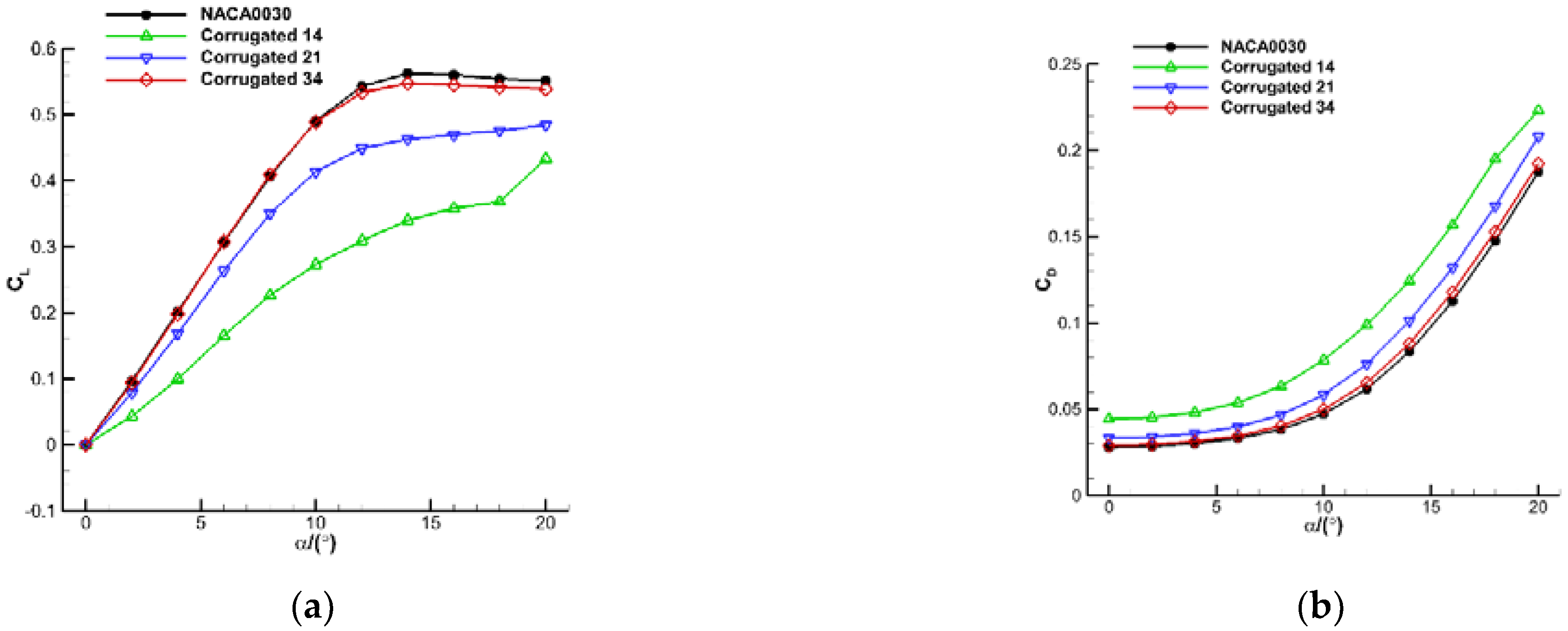
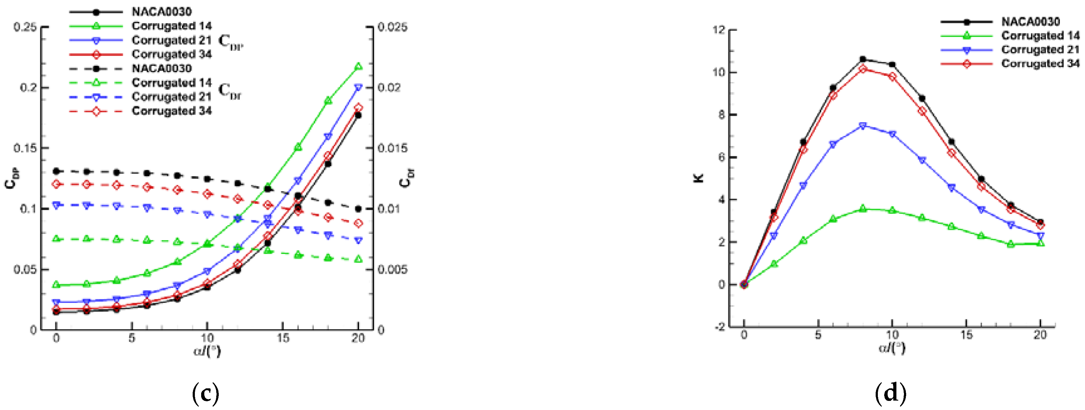
3.1. Comparisons of Overall Aerodynamic Characteristics

Figure 5 generally compares time-averaged aerodynamic coefficients with increasing angle of attack. The four sub-figures correspond to the lift coefficient CL, drag coefficient CD, drag components (pressure drag CDP and viscous drag CDf), and the ratio of lift to drag K, respectively. It should be noted that the reference area in calculating lift and drag coefficients was 0.1 m2. For the lift coefficient, it could be found that the higher the smoothness of the corrugated airfoil, the higher the lift was. Moreover, these four airfoils showed similar tendencies at low angles of attack. They all increased linearly when the angle of attack was lower than 10°, and then the increasing rate began to slow down. After that, the lift of the NACA0030 began to decrease after achieving its maximum value at 14°. Because the Corrugated 34 airfoil is closest to the baseline airfoil, its lift is close to the NACA0030, only slightly smaller. However, for the two corrugated airfoils, Corrugated 14 and Corrugated 21, although the lift coefficients are much smaller than the baseline, their values continued to increase until 20°.
In terms of the total drag coefficient, for the baseline airfoil, the coefficient increased slowly at the lower angle of attack, and after that, the coefficient increased rapidly. For the three corrugated airfoils, the drag was reduced as the smoothness of the airfoil improved. Therefore, the Corrugated 34 airfoil appears close to the baseline, the Corrugated 21 is greater, and the Corrugated 14 is most significantly different compared with the baseline.
In terms of viscous drag, with the increase of angle of attack, the values for all four airfoils decreased slowly, and the higher the smoothness of the airfoil, the higher the viscous drag was. For example, the viscous drag for Corrugated 14 airfoil was 60% of the smooth airfoil, and for Corrugated 21 and Corrugated 34, the percentage was 70% and 90%, respectively. Furthermore, the reason is that the trapped vortex of the corrugations and separated flow at higher angles of attack reverse the local flow direction so that friction decreases compared with the flow field without any vortex. This is displayed later in following sections. The pressure drag for all four airfoils increased slowly at lower angles of attack and rapidly after 8°. The most corrugated airfoil (Corrugated 14) had the biggest pressure drag. Because the pressure drag is about one order of magnitude larger than the viscous drag, the changing tendency of total drag was similar to pressure drag.
As can be seen from the lift-to-drag ratio, the aerodynamic efficiency of a corrugated airfoil is less than that of a smooth airfoil because of smaller lift and greater drag. However, it should be noted that for the first corrugated airfoil, the decreasing rate of aerodynamic efficiency was significantly lower than that of the smooth NACA0030 airfoil.

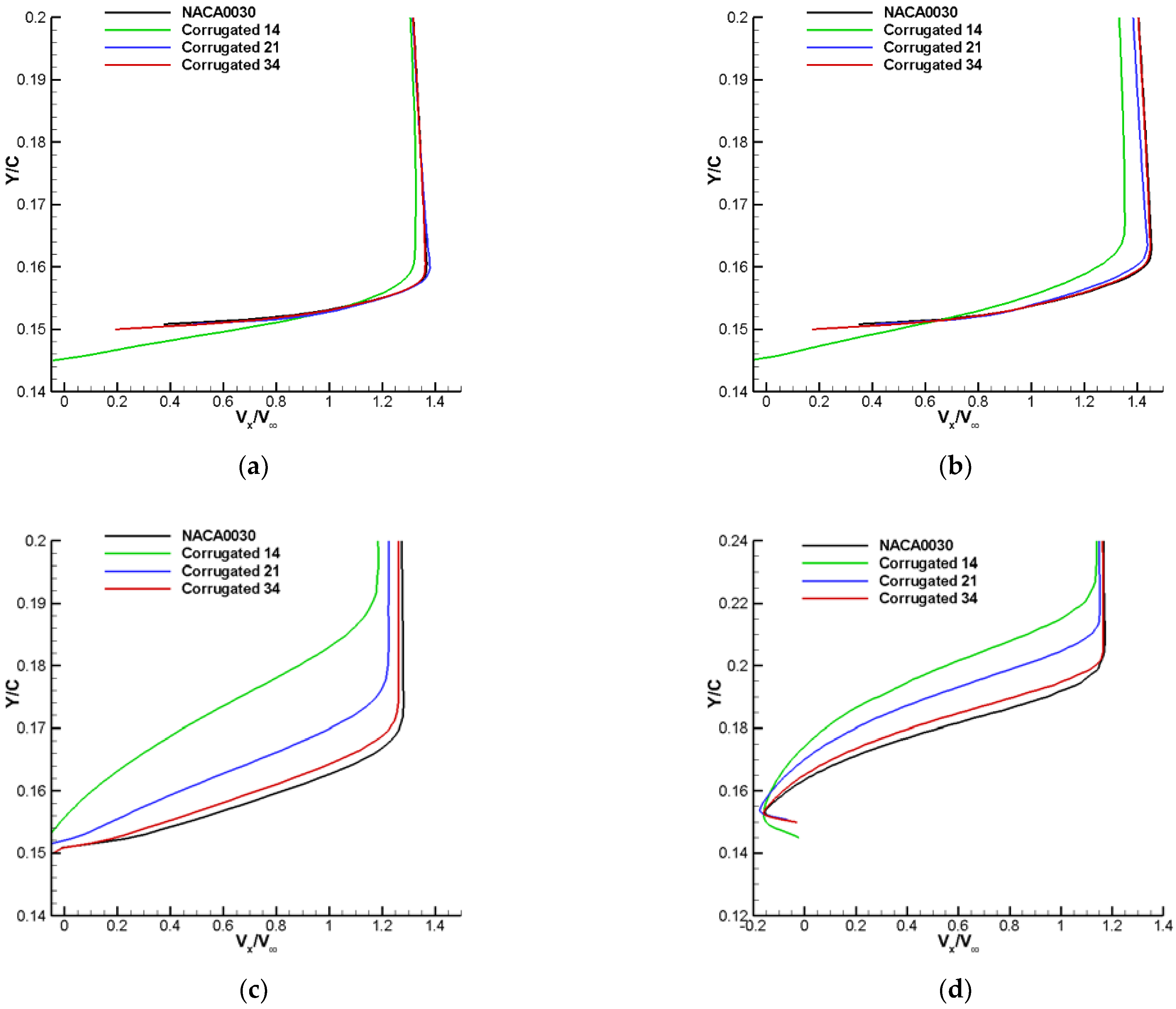
3.2. Comparisons of Boundary Layer Development

Figure 6 displays the stream-wise velocity distributions in the boundary layers for these four airfoils at the upper surface at a 30% chord-wise position at four different selected angles of attack. It should be noted here that for the NACA0030 airfoil, the maximum thickness was located at a 30% chord. As depicted in Figure 2, the position of the upper surface of the Corrugated 14 airfoil was at a valley of corrugations while the other two were nearly at the peak of corrugations. Thus, it can be determined that the stream-wise velocity was negative for the Corrugated 14 airfoil even at small angles of attack because of the recirculating flow caused by the trapped vortex in the valley. At 0°, Corrugated 14 had the greatest velocity gradient variation and thickness for the boundary layer, while the other three airfoils behaved nearly in the same way. At 8°, the boundary flow for Corrugated 21 and Corrugated 34 increased its velocity gradient and boundary thickness. At 16°, the velocity gradient variations of Corrugated 21 and Corrugated 34 were slightly bigger than the baseline NACA0030 airfoil and had a tendency to behave in a laminar way. However, the boundary layer for Corrugated 14 behaved more turbulently and with a much greater velocity gradient and boundary thickness. At 20°, because of the effect of large, separated flow at the trailing edge, all the flow directions closest to the wall were negative. Therefore, the Corrugated 14 airfoil showed the boundary layer’s most apparent velocity gradient and thickness. In general, the boundary layer of a corrugated airfoil was characterized by turbulent flow while that of the baseline airfoil was laminar.

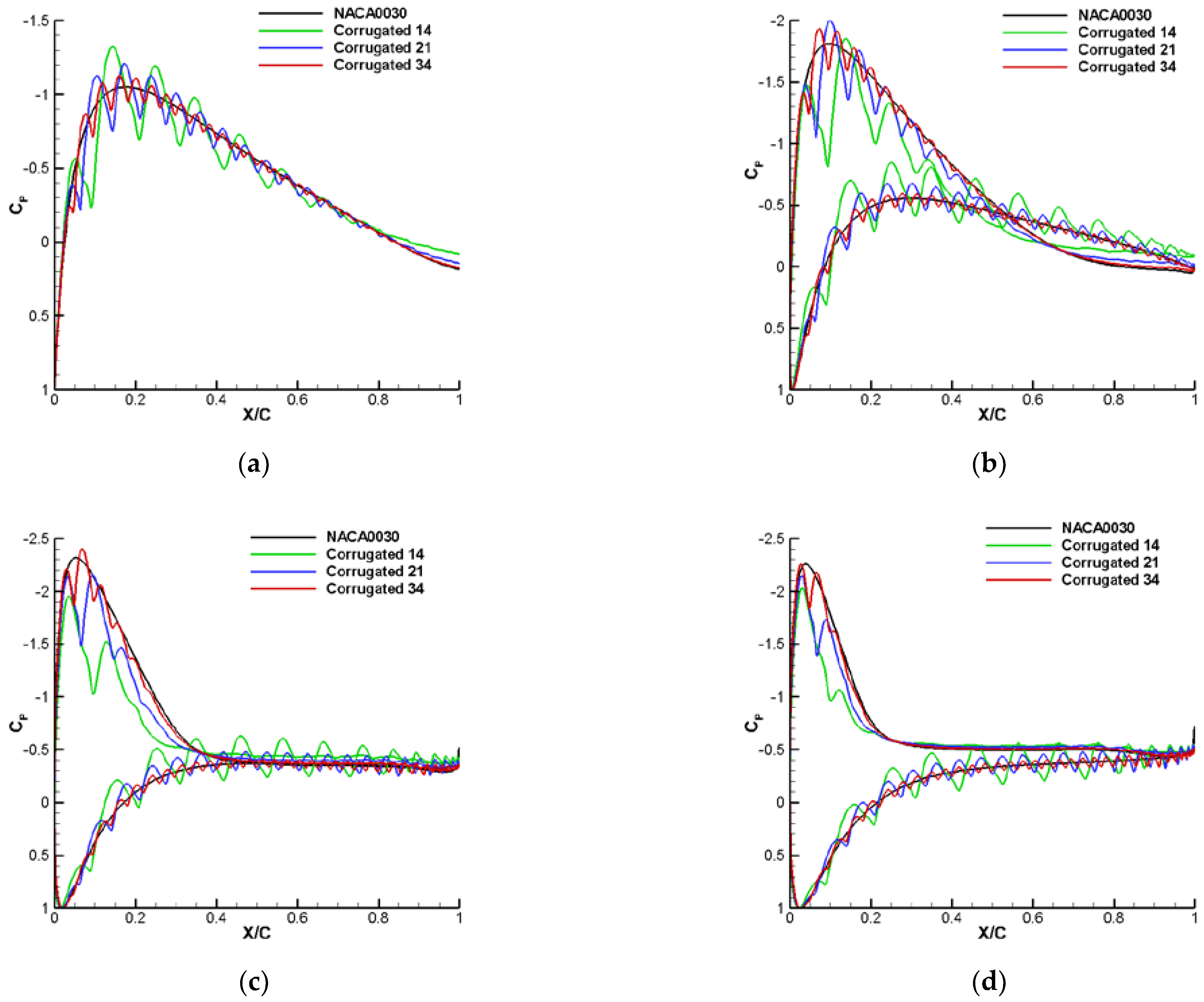
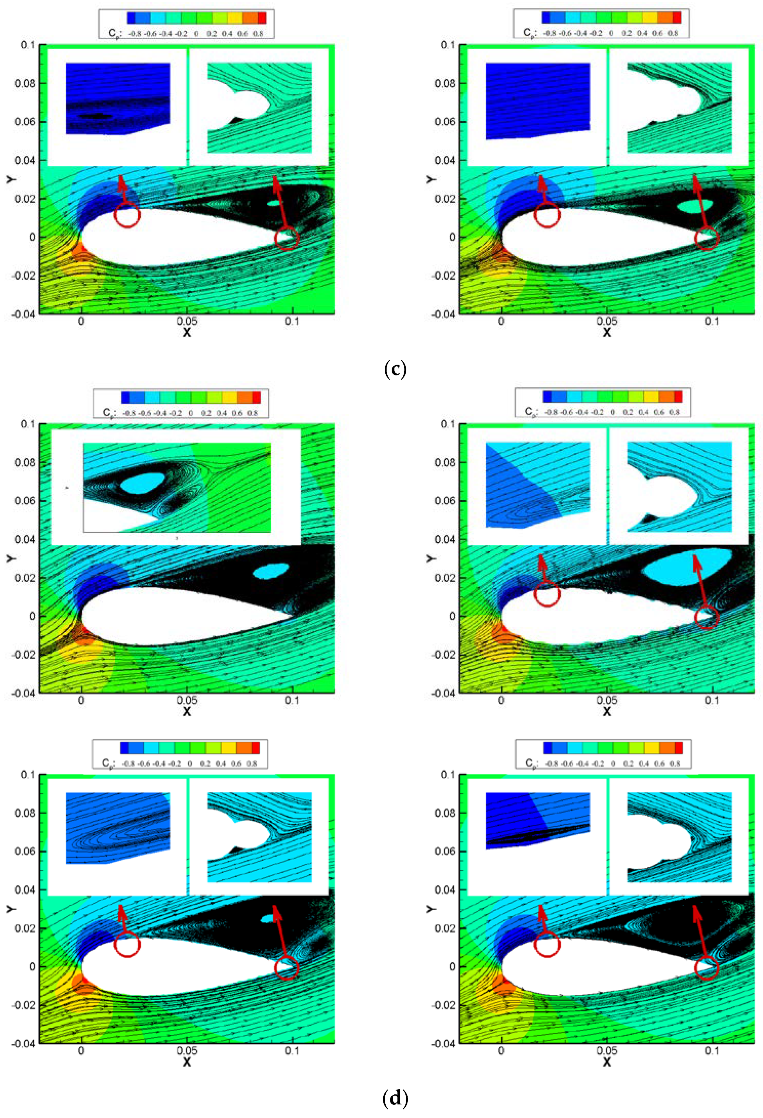
3.3. Comparisons of Streamlines and Pressure Distributions

Because pressure differentials between the upper and lower surfaces directly determine the aerodynamic coefficients, the detailed surface pressure distributions, flow streamlines, and flow field structures at selected angles of attack from 0° to 20° are presented in Figure 7 and Figure 8, respectively, to elucidate the underlying physics of the aerodynamic effects of airfoils with different levels of corrugation at low Reynolds numbers.
At 0°, pressure distributions and streamlines at the upper and lower surfaces of all four airfoils were coincident because of geometric symmetry. Moreover, for the corrugated airfoils, the pressure distribution oscillated because of the corrugated surface. Besides, there was no visible, separated vortex (only a long bubble) at the trailing edge of the baseline airfoil. However, for the corrugated airfoils, the vortex in the corrugations close to the trailing edge merged into a separate vortex. In addition, for Corrugated 14 and Corrugated 21, the flow trapped in the corrugation at maximum thickness showed a clear vortex structure. In contrast, for Corrugated 34, the flow at this position was laminar, so the former two corrugated airfoils had a smaller viscous drag because of these reversed flows in corrugations, as illustrated in Figure 5c.
As the angle of attack increased to 8°, there was an evident separation flow on the upper surface at the trailing edge for the baseline airfoil, so the pressure on the upper surface was higher than the lower surface at these vortex zones. However, because of the increased angle of attack, the upper pressure at maximum thickness had a significant decrement, and the lower surface had a noticeable increment, so the lift at 8° showed a prominent increment compared with the lift at 0°. Similarly, the lift increased for the corrugated airfoils because of a greater vortex merged with trapped vortices in corrugations at the trailing edge’s upper surfaces. The pressure distribution here was smoothly distributed, while at other positions, it was still oscillating. As a result, the vortex size at the trailing edge was greater than 0°, the separated vortex for Corrugated 14 was more significant, the separation point for Corrugated 14 was closer to the leading edge compared with other airfoils, and the aerodynamic characteristics of Corrugated 34 were almost the same as the baseline airfoil.
When the angle of attack increased to 16°, the separated vortex flow continued to grow and move forward. Moreover, for the baseline airfoil, at the separated zone, the upper and lower surface pressure distributions were nearly the same. However, because the separated zone increased, the lower surface zone before the separated flow on the upper surface slightly reduced, so the lift was reduced compared with 8°. For the corrugated airfoil, the corrugations produced consistently lower pressure at upper surfaces greater than 8°, so their lifts were still increasing. It should be noted that there was still no vortex in the corrugation at the maximum thickness of the Corrugated 34 airfoil, so the aerodynamic characteristics of Corrugated 34 were almost the same as the baseline airfoil.
When the angle of attack increased to 20°, the separated vortex flow continued to grow and move forward. Furthermore, for the baseline airfoil, at the separated zone, pressure distributions of the upper surface were lower than those of the lower surface. However, because the separated zone increased, the lower surface zones before the separated flow on the upper surface was reduced, so the lift was reduced compared with 16°. For the corrugated airfoil, the corrugations produce consistently lower pressure at upper surfaces greater than 16°, so their lifts were still increasing. Finally, it should be noted that a visible vortex existed in the corrugation at the maximum thickness for the Corrugated 34 airfoil.
In conclusion, the corrugation peaks acted as vortex generators to promote the transition of the boundary layer from laminar to turbulent while keeping attached to the surface because of the high-speed outer flow. In addition, the valleys of the corrugations trapped unsteady vortex structures and helped the boundary layer become more energetic and stay attached by pulling high-speed flow into near-wall lower-pressure regions. By these two processes, the corrugated airfoil can provide sufficient kinetic energy within the boundary layer flow to overcome the adverse pressure gradient, thus suppressing large-scale flow separation and delaying airfoil stalling at a higher angle of attack.

4. Conclusions

To improve our understanding of the underlying physics of corrugation features found in insect wings or inflatable wings at low Reynolds number flight, and to explore the potential applications of non-traditional, bio-inspired corrugated airfoils for inflatable wing applications, a detailed computational study was carried out by ANSYS Fluent to investigate the aerodynamic characteristics and flow field features around a group of corrugated airfoils compared with a traditional smooth-surfaced NACA0030 airfoil at chord-based Reynolds number 1.2 × 10⁵. As far as we know, this work is the first computational study comparing the aerodynamic effect of corrugated airfoils with different levels of corrugation. After a thorough analysis of these computational results, the following conclusions could be obtained:
(1)
For corrugated airfoil used for inflatable wing structures, the aerodynamic efficiency was reduced compared with smooth baseline airfoils with the same thickness because of lower lift and higher pressure drag. However, the viscous drag decreased because of small recirculating vortices generated in the valley of corrugations—the more corrugated the airfoil, the worse the aerodynamic efficiency.
(2)
For corrugated airfoil, the stall characteristics could be improved because of the corrugations. Furthermore, at a higher angle of attack, the increase in the lift is because of the negative pressure produced at the valleys of the corrugated airfoil.
(3)
For corrugated airfoils, the flow field and development of boundary layers around the airfoils behaved in a more complicated and unsteady way than for the smooth airfoil because of trapped vortices in corrugations. These vortices move outwardly at an increasing angle of attack and eventually merge into the separated flow at the trailing edge at a higher angle of attack.
Our work investigated the aerodynamic characteristics of several corrugated airfoils in a low Reynolds number regime. However, the gust response and stability must be validated before corrugated wings can be applied extensively in inflatable flight vehicles.

Author Contributions

Q.Z.: Computational investigations, data analysis, writing—original draft preparation, R.X.: writing—review and editing, funding acquisition. All authors have read and agreed to the published version of the manuscript.

Funding

This research was funded by the National Natural Science Foundation of China (Grant Nos. 62175243, 12202331), Guangdong Basic and Applied Basic Research Foundation (Grant No. 2021A1515110002), Natural Science Basic Research Program of Shaanxi (Grant No. 2022JQ–028).

Data Availability Statement

The datasets generated or analyzed during this study are available from the corresponding author on reasonable request.

Acknowledgments

The computational work was carried out in the Gekko Cluster in High Performance Computing Centre in Nanyang Technological University, and the work in this paper could not be accomplished successfully without the technical support from School of Mechanical & Aerospace Engineering, Nanyang Technological University.

Conflicts of Interest

The authors declare that they have no known competing financial interests or personal relationships that could have appeared to influence the work reported in this paper.

References

  1. Ortega, E.; Flores, R.; Cuartero, E.; Oñate, E. Efficient aeroelastic analysis of inflatable structures using enhanced potential flow aerodynamics. J. Fluids Struct. 2019, 90, 230–245. [Google Scholar] [CrossRef]
  2. Haight, A.E.H.; Jacob, J.D.; Scarborough, S.E.; Gleeson, D. Hybrid inflatable rigidizable wings for high altitude applications. In Proceedings of the 50th AIAA/ASME/ASCE/AHS/ASC Structures, Structural Dynamics, and Materials Conference, AIAA, Palm Springs, CA, USA, 4–7 May 2009; pp. 2009–2148. [Google Scholar]
  3. Norris, R.K.; Pulliam, W.J. Historical perspective on inflatable wing structures. In Proceedings of the 50th AIAA/ASME/ASCE/AHS/ASC Structures, Structural Dynamics, and Materials Conference, AIAA, Palm Springs, CA, USA, 4–7 May 2009; pp. 2009–2145. [Google Scholar]
  4. Zhao, B.; Hu, J.; Chen, W.; Chen, J.; Qiu, Z.; Jing, Z. Computational method for in-situ finite element modeling of inflatable membrane structures based on geometrical shape measurement using photogrammetry. Comput. Struct. 2019, 224, 106105. [Google Scholar] [CrossRef]
  5. Grover, M.R.; Cichy, B.D.; Desai, P.N. Overview of the Phoenix entry, descent, and landing system architecture. J. Spacecr. Rocket. 2011, 48, 706–712. [Google Scholar] [CrossRef]
  6. Li, S.; Jiang, X.Q. Review and prospect of guidance and control for mars atmospheric entry. Prog. Aerosp. Sci. 2019, 69, 40–57. [Google Scholar] [CrossRef]
  7. Zhang, Q.; Ye, Z.Y. Computational investigations for aerodynamic characteristic analysis of low Reynolds number doubly-tandem wing configurations. Eng. Mech. 2019, 36, 244–256. (in Chinese). [Google Scholar]
  8. Zhang, Q.; Ye, Z.Y. Aerodynamic exploration for wavy airfoil based on NACA0030. J. Beijing Uni. Aeron. Astron. 2021, 47, 1138–1144. (in Chinese). [Google Scholar]
  9. Hu, H.; Tamai, M. Bioinspired corrugated airfoil at low Reynolds numbers. J. Aircr. 2008, 45, 2068–2077. [Google Scholar] [CrossRef]
  10. Murphy, J.T.; Hu, H. An experimental study of a bio-inspired corrugated airfoil for micro air vehicle applications. Exp. Fluids 2000, 49, 531–546. [Google Scholar] [CrossRef]
  11. Yokozeki, T.; Sugiura, A.; Hirano, Y. Development of variable camber morphing airfoil using corrugated structure. J. Aircr. 2000, 51, 1023–1029. [Google Scholar] [CrossRef]
  12. Meng, X.G.; Sun, M. Aerodynamic effects of wing corrugation at gliding flight at low Reynolds numbers. Phys. Fluids 2000, 25, 071975. [Google Scholar] [CrossRef]
  13. Hord, K.; Liang, Y. Numerical investigation of the aerodynamic and structural characteristics of a corrugated airfoil. J. Aircr. 2000, 49, 749–757. [Google Scholar] [CrossRef]
  14. Flint, T.J.; Jermy, M.C.; New, T.H.; Ho, W.H. Computational study of a pitching bio-inspired corrugated airfoil. Int. J. Heat Fluid Flow 2000, 65, 328–341. [Google Scholar] [CrossRef]
  15. Tang, H.; Lei, Y.L.; Li, X.Z.; Fu, Y. Numerical investigation of the aerodynamic characteristics and attitude stability of a bio-inspired corrugated airfoil for MAV or UAV applications. Energies 2000, 12, 4021. [Google Scholar] [CrossRef]
  16. Barnes, C.J.; Visbal, M.R. Numerical exploration of the origin of aerodynamic enhancements in low-Reynolds number corrugated airfoils. Phys. Fluids 2000, 25, 115106. [Google Scholar] [CrossRef]
  17. Shi, X.; Huang, X.W.; Zheng, Y.; Zhao, S.S. Effects of cambers on gliding and hovering performance of corrugated dragonfly airfoils. Int. J. Numer. Methods Heat Fluid Flow 2000, 26, 1092–1120. [Google Scholar] [CrossRef]
  18. Jain, S.; Bhatt, V.D.; Mittal, S. Shape optimization of corrugated airfoils. Comput. Mech. 2015, 56, 917–930. [Google Scholar] [CrossRef]
  19. Levy, D.E.; Seifert, A. Simplified dragonfly airfoil aerodynamics at Reynolds numbers below 8000. Phys. Fluids 2009, 21, 071901. [Google Scholar] [CrossRef]
  20. Kesel, A.B. Aerodynamic characteristics of dragonfly wing sections compared with technical aerofoils. J. Exp. Biol. 2000, 203, 3125–3135. [Google Scholar] [CrossRef]
  21. Okamoto, M.; Yasuda, K.; Azuma, A. Aerodynamic characteristics of the wings and body of a dragonfly. J. Exp. Biol. 2000, 199, 281–294. [Google Scholar] [CrossRef]
  22. Zhang, Z.; Yin, Y.; Zhong, Z.; Zhao, H. Aerodynamic performance of dragonfly wing with well-designed corrugated section in gliding flight. Comp. Model. Eng.Sci. 2015, 109, 285–302. [Google Scholar]
  23. Vargas, A.; Mittal, R.; Dong, H. A computational study of the aerodynamic performance of a dragonfly wing section in gliding flight. Bioinspir. Biomim. 2008, 3, 026004. [Google Scholar] [CrossRef] [PubMed]
  24. Ho, W.H.; New, T.H. Unsteady numerical investigation of two different corrugated airfoils. Proc. Inst. Mech. Eng. Part G J. Aerosp. Eng. 2017, 231, 2423–2437. [Google Scholar] [CrossRef]
  25. Zhang, Q.; Ye, Z.Y. Novel method based on inflatable bump for vertical tail buffeting suppression. J. Aircr. 2015, 52, 367–371. [Google Scholar] [CrossRef]
  26. Zhang, Q.; Hua, R.H.; Ye, Z.Y. Experimental and computational investigation of novel vertical tail buffet suppression method for high sweep delta wing. Sci. China Technol. Sci. 2015, 58, 147–157. [Google Scholar] [CrossRef]
  27. Lian, Y.S.; Shyy, W. Laminar-turbulent transition of a low Reynolds number rigid or flexible airfoil. AIAA J. 2007, 45, 1501–1513. [Google Scholar] [CrossRef] [Green Version]
Figure 1. Sketch of the airfoil for an inflatable wing. (a) Multi-beam wing section. (b) Multi-tube wing section.
Aerospace 10 00174 g001
Figure 2. Comparison of the corrugated airfoil.
Aerospace 10 00174 g002
Figure 3. Computational grid distribution at different positions: (a) Far-field, (b) Boundary layer of NACA0030, and (c) Boundary layer of a corrugated airfoil (Corrugated 14).
Aerospace 10 00174 g003
Figure 4. Comparison of pressure coefficients for SD 7003 at an angle of attack 4°.
Aerospace 10 00174 g004
Figure 5. Time-averaged aerodynamic coefficients for corrugated airfoils and smooth airfoils: (a) Lift coefficient CL, (b) Drag coefficient CD, (c) Coefficients of pressure drag CDP and viscous drag CDf, (d) Lift-to-drag ratio K.
Aerospace 10 00174 g005aAerospace 10 00174 g005b
Figure 6. Time-averaged stream-wise velocity profile at the upper surface with x/c = 30% chord-wise position: (a) 0°, (b) 8°, (c) 16°, and (d) 20°.
Aerospace 10 00174 g006
Figure 7. Comparisons of wall pressure coefficient at different angles of attack: (a) 0°, (b) 8°, (c) 16°, and (d) 20°.
Aerospace 10 00174 g007
Figure 8. Comparisons of pressure field and streamlines for NACA0030 and the three corrugated airfoils at different angles of attack: (a) 0°, (b) 8°, (c) 16°, and (d) 20°.
Aerospace 10 00174 g008aAerospace 10 00174 g008bAerospace 10 00174 g008c
Table 1. Comparison of lift and drag coefficients by different computational methods.
MethodCL (Relative Error)CD (Relative Error)
Ref. [27]0.5610.021
inviscid0.6541 (16.60%)0.0025 (−88.10%)
S–A0.5561 (−0.87%)0.0219 (4.29%)
γ–Reθ transition0.5654 (0.78%)0.0223 (6.19%)
Disclaimer/Publisher’s Note: The statements, opinions and data contained in all publications are solely those of the individual author(s) and contributor(s) and not of MDPI and/or the editor(s). MDPI and/or the editor(s) disclaim responsibility for any injury to people or property resulting from any ideas, methods, instructions or products referred to in the content.

