Article

Design Exploration for Sustainable Regional Hybrid-Electric Aircraft: A Study Based on Technology Forecasts

1
Department of Industrial Engineering, University of Naples “Federico II”, 80125 Naples, Italy
2
SmartUp Engineering S.r.l., 80123 Naples, Italy
3
Department of Electrical Engineering, Institute of Power Electronics, Friedrich-Alexander-Universität Erlangen-Nürnberg, 90429 Nuremberg, Germany
4
School of Engineering and Computer Science, BFH Energy Storage Research Centre, Bern University of Applied Sciences, 3001 Bern, Switzerland
*
Author to whom correspondence should be addressed.
Aerospace 2023, 10(2), 165; https://doi.org/10.3390/aerospace10020165
Submission received: 30 December 2022 / Revised: 3 February 2023 / Accepted: 7 February 2023 / Published: 10 February 2023
(This article belongs to the Special Issue Turboprop Aircraft Design and Optimization)

Abstract

:
The environmental impact of aviation in terms of noise and pollutant emissions has gained public attention in the last few years. In addition, the foreseen financial benefits of an increased energy efficiency have motivated the transport industry to invest in propulsion alternatives. This work is collocated within the Clean Sky 2 project GENESIS, focused on the environmental sustainability of 50-passenger hybrid-electric aircraft from a life-cycle-based perspective to support the development of a technology roadmap for transitioning towards sustainable and competitive electric aircraft systems. While several studies have already focused on the definition of possible aircraft designs combining several propulsion systems, the novelty of the present work is to consider technology forecasts and more comprehensive indicators in the design phase. These include the performance and emissions on a 200 nmi typical mission, which reflects the most economically attractive range for aircraft in the regional class. The work proposes a complete exploration of three major technology streams for energy storage: batteries, fuel cells, and turbine internal combustion engine generators, also including possible combinations of those technologies. The exploration was carried out through the execution of several designs of experiments aiming at the identification of the most promising solutions in terms of aircraft configuration for three different time horizons: short-term, 2025–2035; medium-term, 2035–2045; and long-term, 2045–2050+. As a result, in the short-term scenario, fuel energy consumption is estimated to be reduced by around 24% with respect to conventional aircraft with the same entry-into-service year thanks to the use of hybrid propulsive systems with lithium batteries. Fuel saving increases to 45% in the medium-term horizon due to the improvement in the energy density of storage systems. By the year 2050, when hydrogen fuel cells are estimated to be mature enough to completely replace kerosene-based engines, the forthcoming hybrid-electric aircraft promise no NOx and CO2 direct emissions, while being approximately 50% heavier than conventional ones.

1. Introduction

This paper is framed in the context of the GENESIS Project (Gauging the ENvironmEntal Sustainability of electrIc and hybrid aircraft Systems), which complies with the European Union topic JTI-CS2-2020-CFP11-THT-13 (Sustainability of Hybrid-Electric Aircraft System Architectures) as part of the Clean Sky 2 programme for Horizon 2020 (project website: https://www.genesis-cleansky.eu/, accessed on 7 February 2023). The GENESIS project will gauge the environmental sustainability of electric aircraft from a life-cycle-based foresight perspective to support the development of a technology roadmap for transitioning towards sustainable and competitive electric aircraft systems. The focus is on the regional class 50-passenger (PAX) aircraft to identify, design, and prospectively assess the best energy storage and transmission topology. This work was carried out within the first work package of the project, aiming at the definition of scenarios and requirements for future hybrid electrical propulsion.
Global emissions from transport have greatly increased over the past half-century. However, 74.5% of transport emissions come from road vehicles and the global aviation industry produces around 2% of all human-induced Carbon Dioxide (CO2) emissions, and is responsible for 12% of CO2 emissions from all transport sources. Since the entire transport sector accounts for 21% of total emissions, road transport accounts for 15% of total CO2 emissions. Aircraft contribution represented 2.5% of total CO2 emissions in 2018 and 11.6% of transport [1]. However, the increasing perception of the environmental impact due to technological progress drives new demands that the scientific community should face. In the aviation industry, the efficient use of existing technologies and the introduction of new technologies are critical elements of corporate strategy.
One of the main strategies used to limit in-flight emissions of pollutants is to increase the use of electrical energy for propulsive purposes, leading to concepts based on all-electric or hybrid-electric propulsive architectures. Hybrid-electric architectures are one of the rising technological innovations, promising a fuel-efficient future aviation and reducing emissions both in terms of polluting gases and noise footprint. Several studies and research projects on the design of hybrid electric aircraft were carried out in recent years [2,3,4,5,6,7,8,9,10,11,12]. Past works have already shown the effects of hybridization at the aircraft level, highlighting that the correct choice of the reference technological level is a crucial step to evaluate the real benefits and feasibility of electric aircraft. Voskuijl et al. [6] conducted parametric studies on the degree of hybridization and on the specific energy of the electric storage systems, demonstrating that the feasibility of hybrid-electric concepts is often compromised depending on the technological level of batteries. In the work of Zamboni et al. [8], focused on the design of a 2035 TurboProp (TP) regional aircraft, it was shown that conservative assumptions for the batteries and electrical components lead to a maximum fuel saving of around 5%, corresponding to a weight penalty of 25%, which would not seem to justify the higher level of complexity introduced. More optimistic hypotheses lead to fuel savings of up to 28% instead, with a 24% higher take-off mass. As a conclusion, it is essential that the characteristics of the technologies involved are estimated through accurate foresight analyses rather than conveniently assumed. To fill this gap, the specialized partners of the GENESIS consortium carried out technology performance forecasts on both storage systems and power electronics. The forecasting was based on current trends, historical data, and expert opinions, as well as the theoretical limit of current technologies, to extrapolate their performance for three different Entry Into Service (EIS) years. The data served as the input for the present work, being implemented to design the optimal system in terms of the weight and fuel consumption that will allow for a reduction in emissions. It is important to note that technology performance forecasting is a complex process that involves a combination of data analysis, expert judgment, and scenario-based thinking. Therefore, as technologies are constantly evolving, the process is inherently uncertain.
The hybrid-electric aircraft design problem introduces new coupling between previously distinct disciplines, such as aerodynamics and propulsion, which may only become apparent with multidisciplinary, physics-based analysis [11,12]. Several drawbacks must also be taken into account for a fair assessment of the real benefits of electrification. One important example is given by the weight penalties linked to the energy storage devices and, in general, to the entire generator set [4]. At the same time, the enhanced design flexibility of hybrid-electric configurations enables innovative design solutions such as wingtip propeller installations and Distributed Electric Propulsion (DEP) [13], which gives the possibility of improving the aerodynamics and mitigating weight penalties thanks to the aero-propulsive interaction effects on the wing lift capability [14,15,16,17,18,19,20]. The introduction of electrical components also raises new concerns in terms of safety. While, for this new type of aircraft, certification specifications have not been defined yet, several key hazards have already been identified [4,21], which also contribute to redefining the impact of a failure on the aircraft airworthiness [22]. In light of this complex and multidisciplinary nature of the hybrid-electric aircraft design, a holistic approach is needed that is capable of combining different fields, including structure, aerodynamics, propulsion, mission, and performance analysis, in an optimal synergy. Efforts in this direction have already been spent in the past [7,9,18], forming the basis for the methodologies adopted for the purposes of this work. The authors will briefly present the approach used for the aircraft design, which evaluates the performance, fuel consumption, and emissions of the aircraft through an approach based on the simulation of the flight mission [17,18,19,20,22,23,24]. It is worth noting that the adopted approach does not consist of a detailed real-time simulation of the flight, but rather an evaluation of the energy and power requirements of the aircraft for each time step into which the mission is divided. This physics-based analysis combines a relatively low computational burden with the advantages of a more precise estimation of the real benefits of aircraft hybridization, especially in terms of direct emissions and energy consumption.
The direct environmental impact of hybrid-electric solutions is generally lower than conventional aircraft, but the evaluation of their real sustainability cannot disregard the assessment of indirect impacts, mainly related to the aircraft production and disposal phases, and the production and distribution of alternative energy sources [3]. In addition, the economic attractiveness for potential operators cannot be neglected, combined with the uncertainty of future market demands. One of the main drivers for the exploration of hybrid-electric aircraft is the potential for significant improvements in energy efficiency and reductions in emissions and noise. This is particularly important for regional-class aircraft, which are operated on short-haul routes. A recent and comprehensive review of the state of the art and the main technological areas of electric aviation is provided by Adu-Gyamfi et al. [5], with a particular focus on battery technologies, electric machines, airframe, and propulsion architectures. Their work offers a complete overview of where the technologies currently stand, their future projections, and their challenges. The article also addresses some of the main factors to identify the constraints of technological advancement and regulatory frameworks that could impede the realization and time to market of the proposed electric airplanes. These aspects contribute to making it desirable to study the potential benefits of hybridization from a life-cycle perspective, which represents the ultimate goal of the GENESIS project in which this work fits. Although the scope of the present paper is limited to the assessment of aircraft performance at mission level, it is crucial to lay the foundations for subsequent life-cycle analyses since the early design stages by evaluating comprehensive indicators that directly refer to the expected operational life of the aircraft. In this sense, after having designed the aircraft on the basis of an assigned design mission, its performance was also evaluated on a typical mission, which reflects the most economically attractive range for aircraft in the regional class.
In the present paper, the hybrid design was achieved by exploring the potential of Internal Combustion Engines (ICEs), batteries, and hydrogen-powered Fuel Cell (FC) systems, considering their performance in three different time horizons: short-term, (2025–2035), medium-term, (2035–2045), and long-term, (2045–2050+). The expected improvement in terms of the energy and power density, together with the possibility of combining the technologies, should enable us to overcome their flaws and combine their strengths to make a feasible and performing hybrid-electric regional aircraft. In Section 2, the design chain is described, as well as the MATLAB®-based tool used during the entire process. The starting point for the analyses performed in this work was the definition of Top Level Aircraft Requirements (TLARs), briefly presented in Section 3.1. The set of TLARs was previously determined by performing a detailed market study of the most relevant regional aircraft, both equipped with TP and jet engines. The overall key factor that guided the definition of TLARs was to make the new 50-passenger regional aircraft economically attractive by paying attention to current and future routes. A general overview on the scenarios selected for each of the three time horizons considered in GENESIS is reported in Section 3.2. The purpose was to explore the major technology streams for energy storage, also including possible combinations of them, through the execution of several Design of Experiments (DOEs), aiming at the identification of the most promising solutions in terms of aircraft configurations for the three different time horizons. In Section 3.3, the main performance indicators are reported for each of the key technologies considered. Finally, in Section 4, the results of the design explorations carried out for the three above-mentioned time horizons are presented.

2. Methodology

2.1. HEAD: Hybrid-Electric Aircraft Designer Tool

The growing sensitivity towards environmental sustainability drives the demand for a revolution in the aerospace propulsion sector, requiring a reduction in carbon emissions that cannot avoid the involvement of disruptive technologies and the use of alternative energy sources. The design of new concepts that employ hybrid-electric propulsion architectures represents the most promising solution to the problem, as long as the energy sources considered are renewable. The main innovation of the in-house aircraft design software developed by the University of Naples Federico II (UNINA), named HEAD (an acronym for Hybrid-Electric Aircraft Designer), is the ability to deal with complex propulsive architectures, including more than one propulsion source and DEP, while checking the compliance with respect to aeronautical regulations and design objectives [18]. Introducing a hybrid powertrain within the aircraft architecture demands appropriate design tools to evaluate the effect of several configuration possibilities in a parametric investigation. Although the development of hybrid-electric or full-electric propulsion has led to the proliferation of many concepts over the past decade, due to the absence of industrial data supporting the research, there is still today a lack of conceptual design methods capable of grasping the effects of new propulsive technologies.
HEAD generalizes the classic design chains for conventional aircraft, allowing us to model hybrid-electric architectures, secondary energy sources, fuel cells based on Hydrogen (H2), and distributed electric propulsion. Furthermore, in order to model a wide range of propulsive architectures, a very flexible mathematical definition of the powertrain is incorporated, enabling HEAD to analyze several variants of the logic schemes of an electric propulsion system [7,17,18,25]. A simplistic representation of a general, hybrid series/parallel electric powertrain is given in Figure 1. The presented diagram refers to the case of two energy sources, where the thermal power source is marked as primary ( 1 ° ) source and the electric energy storage as a secondary ( 2 ° ) source. Figure 1 generally corresponds to the serial/parallel hybrid-electric concept, but can also degenerate into several simpler architectures, representative of turbo-electric, serial hybrid-electric, parallel-hybrid electric, and all-electric architectures. In this sense, the flexibility of this model allows for a better optimization of the mission strategy, even allowing us to reverse the operating mode of the elements, with the primary electric machine capable of eventually reversing the direction of the energy flow as needed, working as a motor or generator depending on the flight segment. To better manage all possible combinations, it is feasible to define up to nine different combinations of the direction of the incoming and outgoing powers in the different elements of the propulsive scheme. These so-called operating modes describe all of the possible combinations of using propellers, electric storage, and primary electric machines [7]. Each operating mode can be treated separately by proper systems of linear algebraic equations, generally referred to as powertrain equations. These equations also include the effect of the degree of hybridization and the efficiencies of the individual components of the powertrain at varying operating conditions [24]. In case hydrogen-based Solid Oxide Fuel Cells (SOFCs) or polymer electrolyte membrane fuel cells (PEMFCs) are used instead of kerosene as the primary energy source, fuel cells are considered to be arranged in parallel with the electric-storage devices, as they both supply the electricity in the form of direct current. The architecture model adopted for hydrogen-fuelled concepts is reported in Figure 2.
In order to quantify the degree of hybridization of a hybrid-electric propulsive scheme, two parameters are typically used. The first one is the so-called supplied power ratio, Φ , which is defined as the ratio between the electric power and the total power supplied. In the case of hybrid-electric concepts based on hydrocarbon fuel (Figure 1), the supplied power ratio is defined as [7]
Φ = P E ST P Fuel + P E ST
where P Fuel is the energy extracted from the burnt fuel over time, and P E ST is the power delivered by the battery. In the case of hybrid-electric configurations based on hydrogen fuel cells (Figure 2), the definition of the supplied power ratio is adapted as follows:
Φ = P E ST P H 2 + P E ST
The second key figure of merit used to describe the hybrid architecture is the shaft power ratio, φ , as called in literature [7], which is the ratio of the shaft power provided by the secondary propulsive line with respect to the total shaft power of the propulsive system:
φ = P S 2 P S 1 + P S 2
The secondary propulsion line is used by the authors to model distributed electric propulsion. It is essential to underline that, differently from conventional aircraft, the aero-propulsive interactions of an innovative aircraft featuring DEP cannot be preliminarily determined. Their determination requires the simulation of the flight mission and the querying of an appropriate engine deck to calculate the thrust provided by the propellers, and thus the effect on the aerodynamics of the aircraft in terms of lift and drag [14,15,19]. HEAD can provide a coupling between aerodynamics and the aircraft engine deck and perform a medium-fidelity analysis of the mission profile, measuring the aircraft performance and energetic requirements. Aero-propulsive effects are estimated based on the original approach proposed by Patterson et al. [14,15], which recalls the principles of the momentum theory of propellers. The method allows for an estimation of the increases in the lift and drag coefficients of the wing as a function of the geometry and distribution of propellers, and the thrust provided in the specific condition analyzed.
The architecture model described above is the basis of the design and analysis workflow implemented in HEAD. This tool consists of three separate modules, corresponding to three possibly subsequent activities:
  • The pre-design module, which initializes the aircraft starting from the TLAR on a purely statistical basis [18].
  • The sizing module, where the required powers and energies are initially estimated, allowing the aircraft to be sized [22].
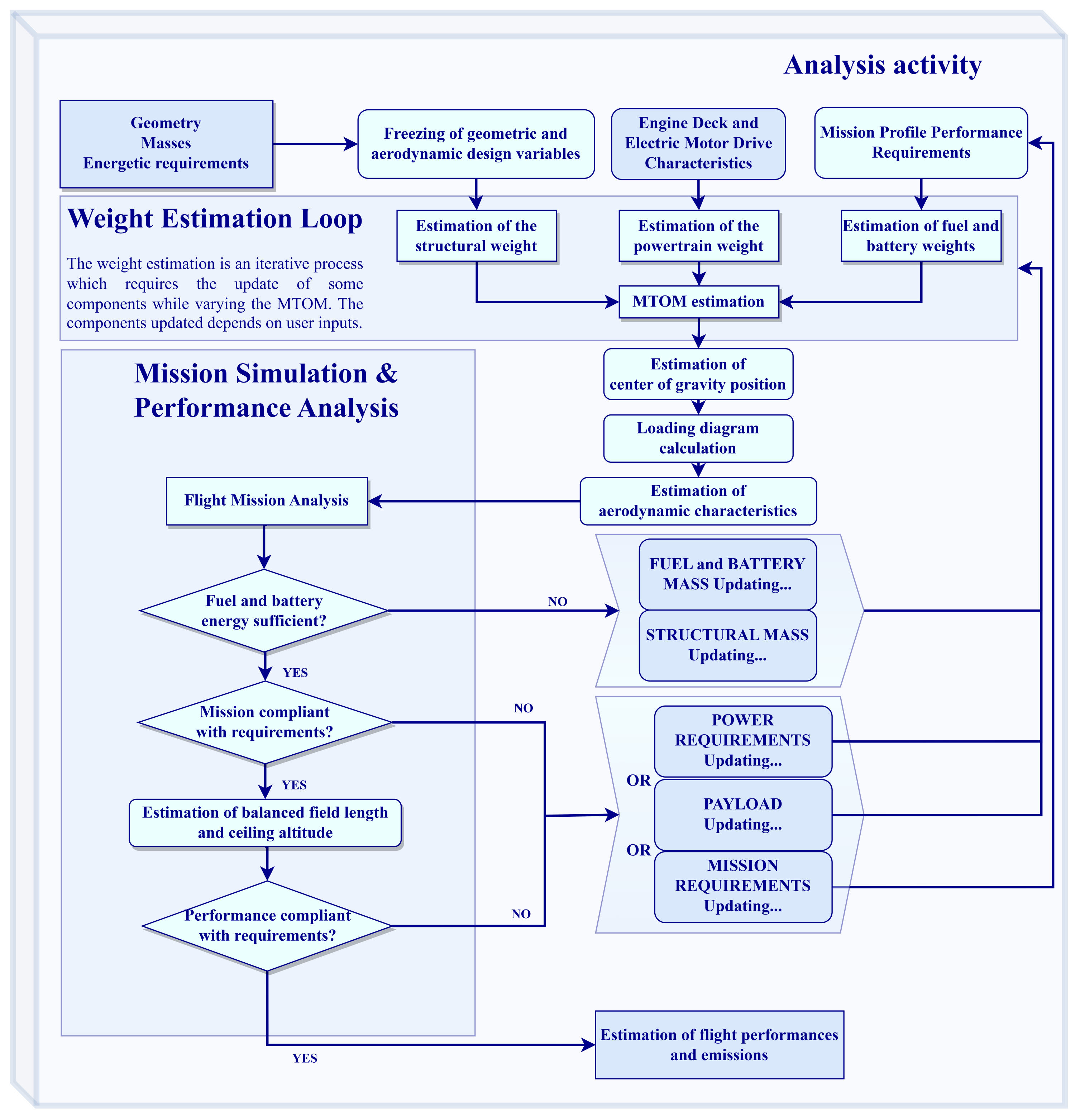
  • Finally, the analysis module, where the aircraft is refined based on the iterated simulation-based analysis of the reference mission [23].
It is anticipated here that, for the particular purposes of the project, it was decided to start from a reference baseline, described in Section 4.1. Thus, the pre-design phase was completely bypassed, and the sizing was incorporated into the mission simulation. More details about the workflow adopted for this work are given in Section 2.2. The analysis activity, described in the flowchart in Figure 3, is an iterative process that aims at estimating the aircraft performance after geometric and aerodynamic characteristics are determined during a previous step of the design loop. The analysis process presented in Figure 3 can be used for investigating the flight performance or designing a platform that would better fulfill mission and performance requirements. To perform a detailed simulation-based mission analysis, it is fundamental to estimate the impact of hybrid-electric propulsion on aircraft flight mission parameters. A simulation-based analysis can be realized only by characterizing every single step of the whole flight mission of an aircraft by its aerodynamic and propulsive features. Therefore, all of the aspects defining the aircraft state at each step, such as the Mach number, altitude, throttle setting, acceleration, rate of climb, etc., must be determined to simulate the flight history. In HEAD, an approach based on a flight simulation is implemented to be able to correctly evaluate the effect of masses and efficiencies in all of the design phases, also integrating weight estimation models that account for masses not typically included in the aircraft pre-design phase. In the context of the GENESIS project, this was useful in order to correctly grasp the effects of the new technologies, modeling both their advantages and disadvantages through the integration of several surrogate models developed by the project partners. This has been possible thanks to a deep interaction between all of the consortium partners, each of which is an expert in a particular field. The surrogate models provided by the partners were integrated into the workflow thanks also to the software architecture of HEAD, composed of several interconnected modules. The integration of surrogate models will be better clarified in Section 2.2. Depending on the flight segment, the three phases of the algorithm are performed at each time step, in an order that depends on the specific flight phase:
  • Starting from flight conditions at the beginning of the flight segment, the aerodynamic characteristics are computed.
  • At the prescribed airspeed and altitude, the power distribution along the propulsive system is determined.
  • Having calculated aerodynamic and propulsive forces, the new flight conditions can be determined.
Here, it is explicitly remarked that, in the case of aero-propulsive interactions, the first and the second steps are chained in an iterative process [20].

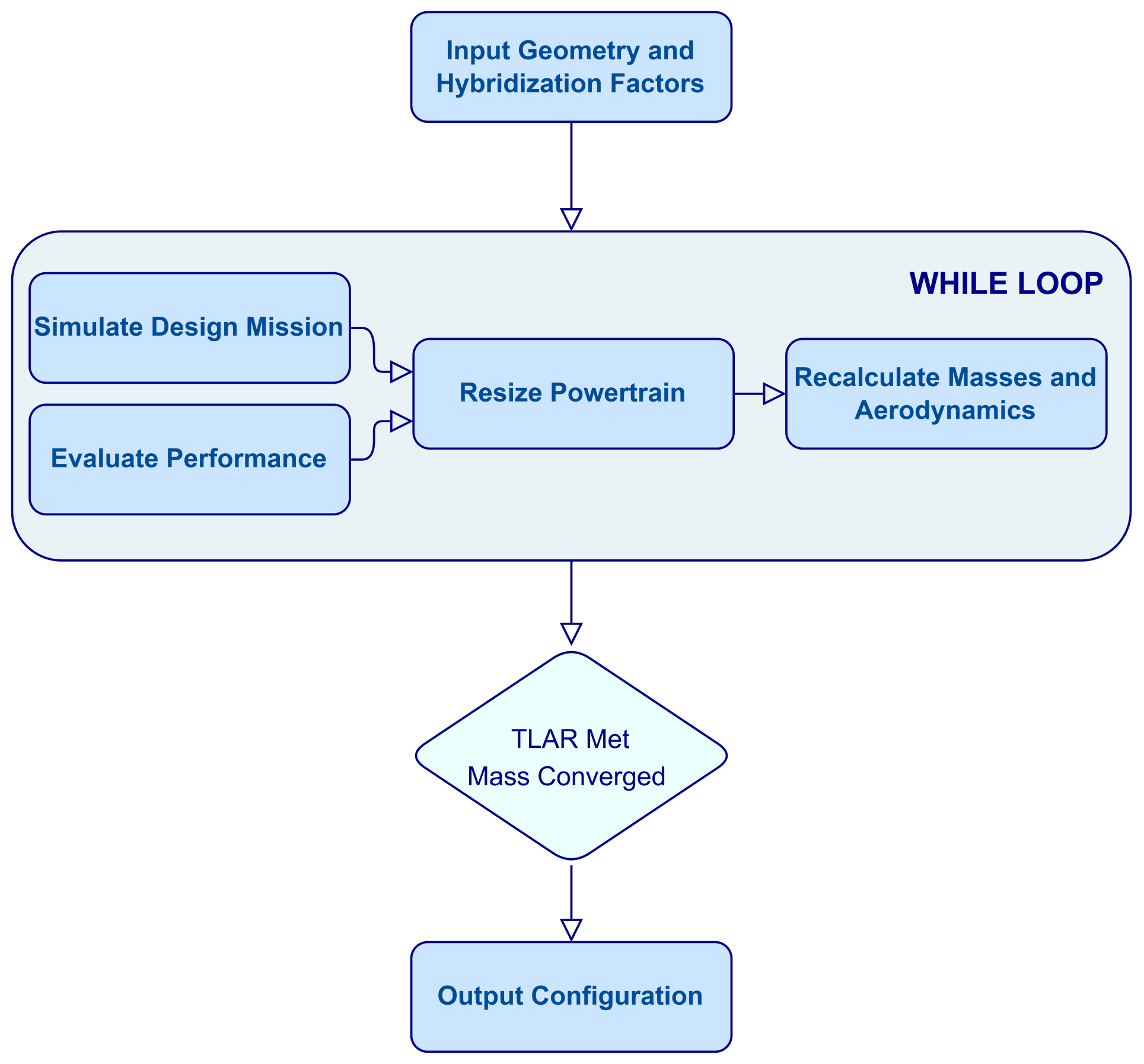
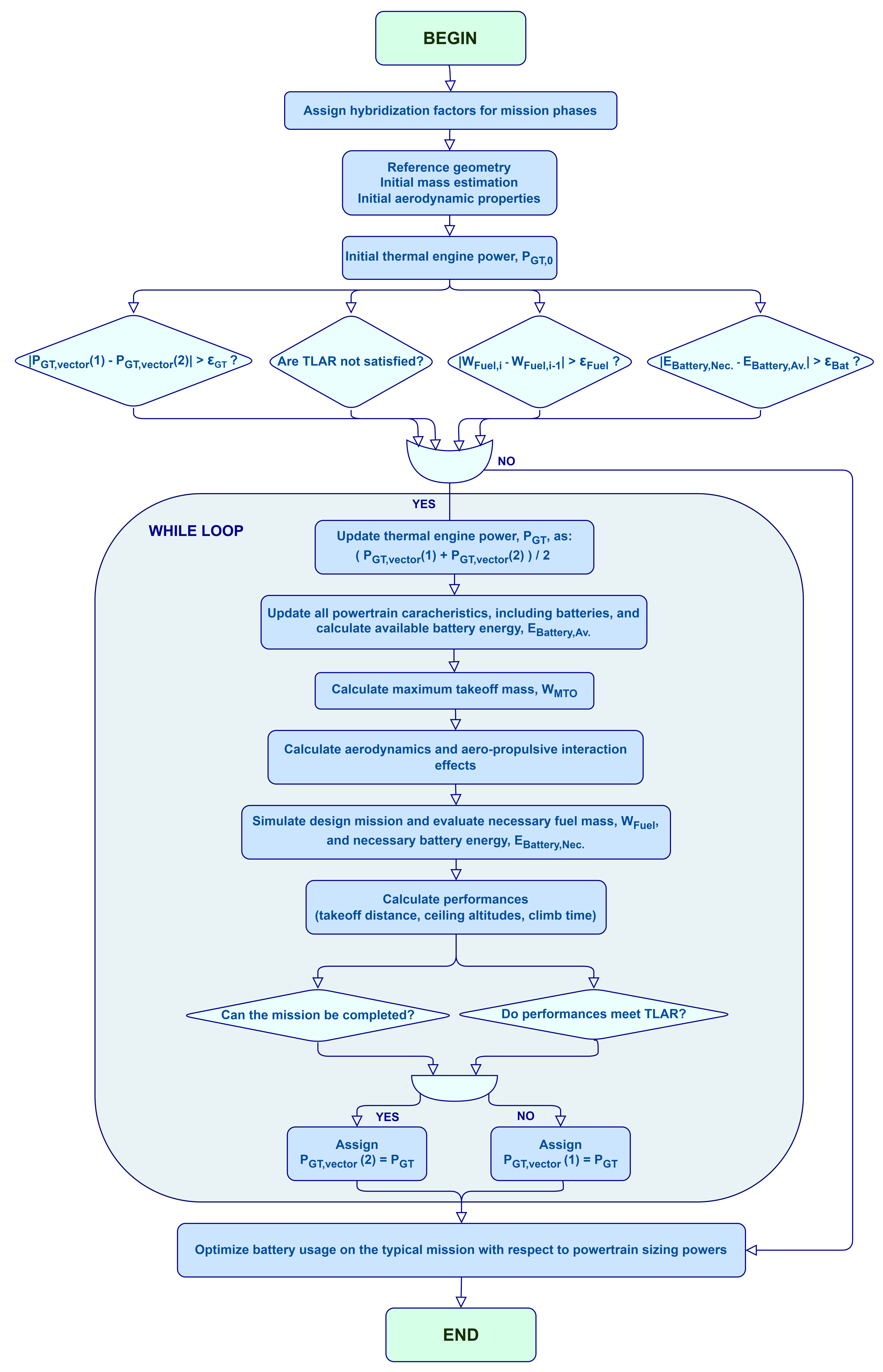
2.2. Design Workflow

The study of hybrid-electric concepts introduces a variety of new design parameters, especially when multiple unconventional power sources are involved. The use of distributed electric propellers suggests the choice of partial serial/parallel hybrid architectures due to the need to manage two independent propulsion lines depending on the flight phase. In the present context, the secondary line is representative of DEP, which is aimed at providing benefits to the aircraft lifting capability during the ground phases. At cruise, in light of the lower efficiency of distributed propellers, it is preferable to deliver all of the shaft power through the primary line, redirecting the energy from the electric storage. The generality of this complex architecture can be managed using the shaft power ratio, which can assume different values between 0 and 1 depending on the flight phase. From the designer’s point of view, the value of the shaft power ratio at take-off is crucial since it not only determines the magnitude of the aero-propulsive effects but also influences the sizing power values for the electrical components of the powertrain (i.e., electric motors and generators). In addition to the management of two propulsive lines, the difficulty that characterizes the design of any electric or hybrid-electric platform is given by the mass of the battery, together with all of the mass penalties collateral to hybridization. The higher the degree of hybridization (i.e., the supplied power ratio in the individual flight phases), the greater the mass of the aircraft. Therefore, for the specific aircraft category under analysis, it is not possible a priori to establish the best degree of hybridization that maximizes the difference between the electrical energy available and the energy necessary for the mission, the latter increasing with the weight of the aircraft itself. This optimum point, which corresponds to the maximum fuel reduction, also depends on the battery use strategy during the flight mission. Using batteries during the longer phases directly reduces the energy extracted from the thermal source. At the same time, the use of the electric power supplied by the battery to the electric motors, in aid of the primary power, compensates for the weight increase of the aircraft itself, avoiding an oversizing of the thermal engines while guaranteeing the same performance. In light of these preliminary considerations, it would not be possible to select the optimal set of hybridization parameters without a careful analysis of the positive and negative effects of each combination. Therefore, the need emerges for a workflow capable of precisely modeling and evaluating all of the effects of hybridization ratios on the performance and fuel consumption. The adopted aircraft design workflow is simply described in Figure 4.
Typically, the conceptual sizing of an aircraft is carried out using a more methodological approach, which can be translated with some modifications to a hybrid-electric airplane, as described by Orefice et al. [18]. However, the application of such a methodological approach may lead to remarkable differences between the performances expected from the sizing and the results deriving from a detailed mission analysis. These differences depend, for example, on assuming constant values for the efficiencies of several powerplant components for the methodological approach. On the other hand, the simulation of the whole mission, involving the interrogation of lookup tables for the efficiencies of gas turbine engines, propellers, and the other powertrain components, can certainly lead to more precise results and to a more consistent design approach. For this reason, as described by Figure 4, the design process was founded in this case on detailed simulation-based mission analyses. A simulation-based analysis is realized by characterizing every single step of the whole flight mission of an aircraft through its aerodynamics, weights, and propulsive features. Therefore, all of the aspects defining the aircraft state at each step, such as the Mach number, altitude, throttle setting, acceleration, rate of climb, etc., must be determined to simulate the flight history. First, the primary geometric characteristics of the aircraft are initialized starting from a baseline aircraft, possibly varying key parameters such as the size of the lifting surfaces. At the same time, hybridization factors are selected for each flight phase. Subsequently, the design mission, modeled on the basis of the assigned set of TLARs, is simulated with time steps of approximately one minute for most of the flight phases. Other parameters, such as the take-off balanced field length and the service ceiling, are also evaluated. If the installed powers are insufficient for completing all the phases of the mission, or for compliance with one or more TLAR, they are adapted contextually. Similarly, powers are reduced when these are exuberant compared to the requirement. The masses of all components and the aerodynamic characteristics (including aero-propulsive effects) are updated accordingly before starting a new mission simulation. The process is also described in more detail in Figure 5. Here, the control variable for convergence is the power of the thermal engine, on whose basis the sizing powers of the other elements (i.e., electric machines, power electronics, battery, fuel cells) are updated.
During the conceptual design phase of a hybrid-electric aircraft, several levels of hybridization are typically investigated based on technological assumptions and future trends for the performance of batteries and fuel cells. The requirement in terms of the gas turbine shaft power at this point is still not precisely set, but it is adjusted during parametric analyses in order to detect the best promising combinations between conventional and advanced propulsive solutions. In order to have more accurate results, a systematic approach, including physics-based considerations derived from actual gas turbine performance models, has been pursued. This approach consisted of implementing a rubber gas turbine engine model into the aircraft design framework adopted for GENESIS, allowing us to easily perform the preliminary sizing of a new ICE by requiring a minimum amount of input information, including the necessary power and supposed level of technology. More information on this scalable engine model is provided in Section 3.2. In the case of concepts based on hydrogen FC, the characteristics of the FC system are remodeled starting from the new power value, including losses linked to the different operating conditions, and the power of the thermal engine is replaced with the power of the FC system as the control variable. In general, this process ensures the aircraft’s ability to complete the mission in compliance with all TLARs, and guarantees a correct and accurate assessment of the aircraft total mass and the fuel required for the flight mission. Moreover, this process ensures that the battery is correctly sized based on the maximum power required during the mission or the total electric energy required, whichever is the most demanding criterion.
The whole design process is based on the simulation of the design mission. However, once the design is completed, a typical off-design mission can also be simulated, with the intent of optimizing the fuel consumption through the best usage profile of the battery, having the sizing powers of individual elements of the powertrain to which the battery is connected as constraints. The described aircraft design workflow allows for designing a new aircraft from scratch, needing only the geometry, propulsive architecture, and degree of hybridization desired for each mission phase as the input. The estimation of masses and efficiencies of structural parts and powertrain components (including batteries, electric machines, and power electronics) takes place in the loop through semi-empirical or surrogate methods provided by the consortium partners, who are experts in the field, thanks to an in-depth exchange of information during the project.
Since the best combination of degrees of hybridization and geometry cannot be known from the beginning, a DOE was carried out for each GENESIS scenario to identify the best combination of these parameters, aiming to minimize emissions. The reason for performing a DOE instead of applying a methodological approach [18] was essentially linked to the intent of the authors to perform the conceptual design by means of refined physics-based methods that size the aircraft on the basis of the real requirements coming from the design mission simulation.
The whole workflow starts with fixing a specific powertrain architecture and choosing a specific set of geometric and hybridization parameters. As mentioned, these critical parameters are not known early in the design process. For this reason, the described workflow was used to create a DOE aimed at exploring a large number of possible combinations of these parameters. For each time horizon, approximately one thousand different aircraft were generated using Latin hypercube sampling, giving up more refined full-factorial explorations to reduce computational costs. Each aircraft was analyzed and sized according to the described process.
The hybridization degrees of freedom chosen for the explorations were reduced to the following, considered the most relevant ones:
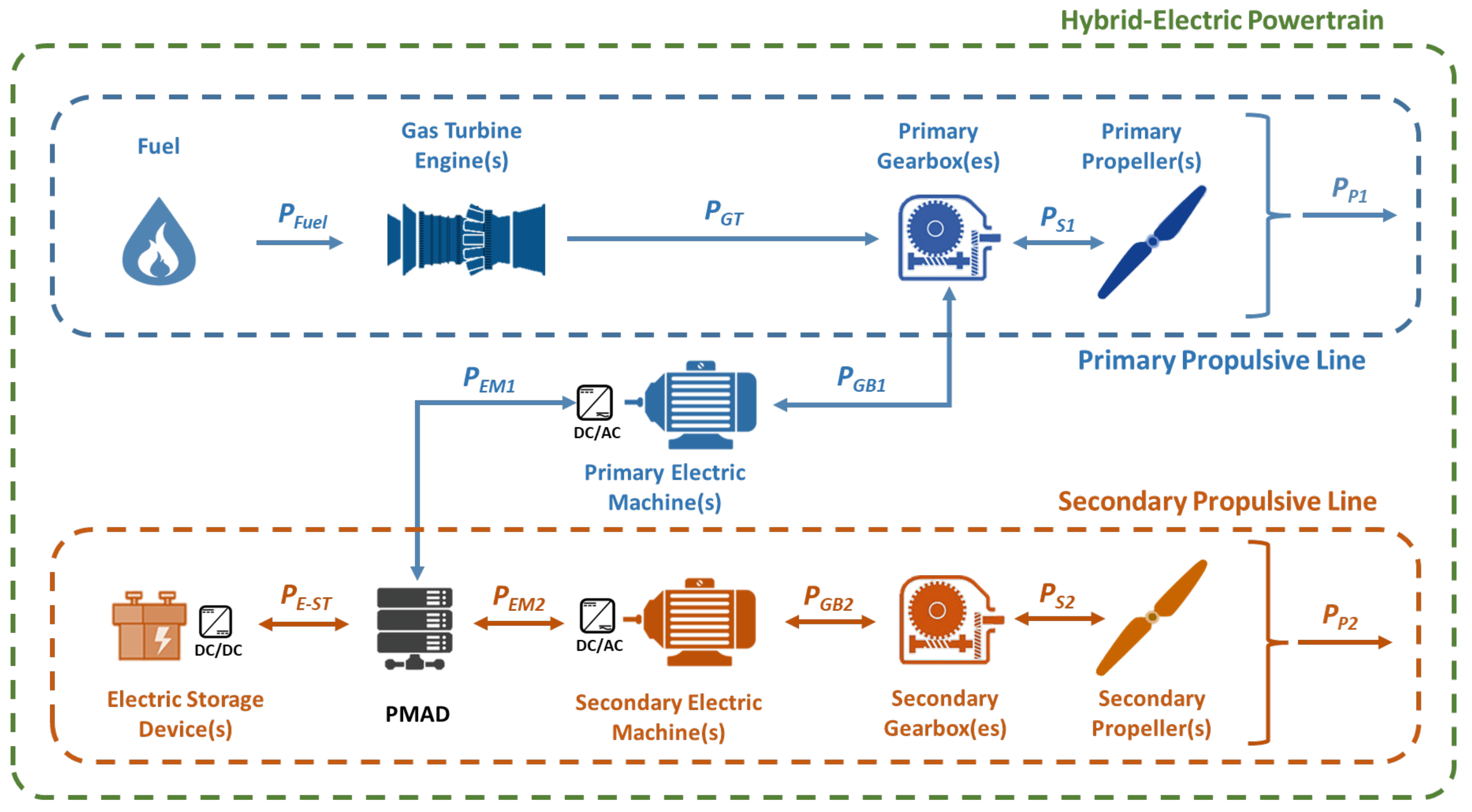
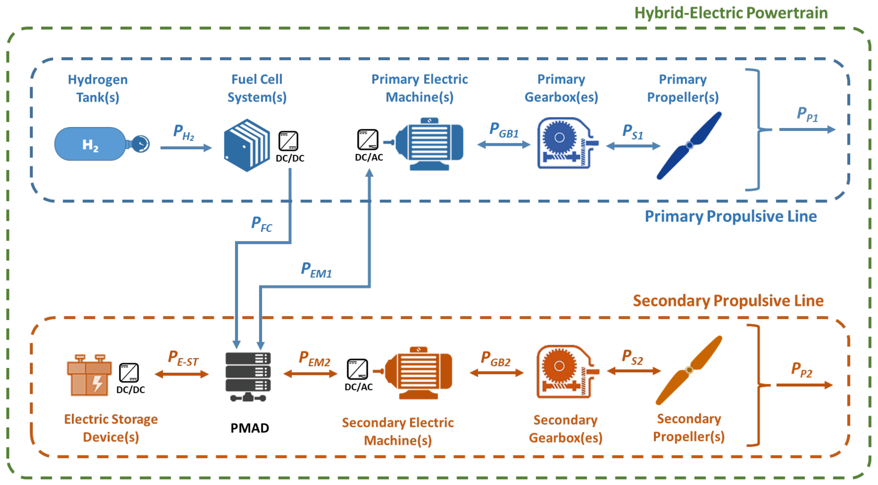
  • Shaft power ratio at take-off, representing the shaft power delivered by the secondary propulsive line with respect to the total shaft power (primary plus secondary line).
  • Supplied power ratio at take-off, representing the fraction of power supplied by the battery system, with respect to the total source power (fuel/hydrogen plus battery), in nominal take-off conditions.
  • Supplied power ratio at climb, representing the fraction of power supplied by the battery system, with respect to the total source power (fuel/hydrogen plus battery), in nominal climb conditions.
  • Supplied power ratio at cruise, representing the fraction of power supplied by the battery system, with respect to the total source power (fuel/hydrogen plus battery), in nominal cruise conditions.
It was assumed that no battery is used during descent, landing, and taxi phases, as well as for the alternate and holding phases. DEP is mainly used in the take-off phase, on the basis of which it is sized. Although it is also used in landing to maximize the lift capabilities of the wing, the effect is small due to the reduced propulsive power. During the cruise phase, the secondary propellers are folded. In addition to hybridization parameters, the most important geometric parameters of the aircraft were also included among the set of DOE variables:
  • Wing planform surface, which impacts the wing wetted area, and thus the lift force and the take-off and landing performance of the airplane, as well as drag characteristics.
  • Wing aspect ratio, which represents the ratio between the square of the wing total span and the wing planform surface, and affects the drag of the airplane.
A strategy was elaborated and implemented to deal with the consistent update of the wing and airplane general geometry when changing the abovementioned wing geometry parameters. When wing parameters are changed with respect to the baseline aircraft wing, original spanwise chord ratios are maintained. First, the wing span is updated based on the new area and aspect ratio. Hence, the chords are lengthened or shortened consistently with the new wing surface and total span values. Finally, the horizontal and vertical tailplanes are also resized to guarantee the same volumetric ratios of the starting baseline aircraft geometry [26]. Although fuselage dimensions are not included in the set of DOE variables, an automatic update of the fuselage length takes place for hydrogen-based configurations to ensure enough space for the hydrogen tanks. The installation of hydrogen tanks was supposed to take place in the rear portion of the fuselage, after the rear bulkhead. Since it is necessary to leave sufficient room in the fuselage tailcone for the installation of an Auxiliary Power Unit (APU) and the controls of tail movables (i.e., elevator and rudder), it is necessary to stretch the cylindrical central portion of the fuselage to allow for the installation of gaseous or cryogenic hydrogen tanks. When the fuselage is stretched, the wing longitudinal position in the body reference frame is automatically updated to keep the original wing attachment relative position with respect to the fuselage of the baseline aircraft. Moreover, horizontal and vertical tail characteristics are accordingly updated by keeping their volumetric ratios constant with respect to baseline values.

3. Definition of Scenarios

3.1. Top-Level Aircraft Requirements

The conceptual design is an iterative process that aims at choosing a single aircraft configuration, which suits the TLARs and aviation regulations requirements. The starting point of the analysis was the market forecast and operational scenarios analysis for a 50-passenger regional aircraft [27]. This has defined a technical benchmark useful for identifying the driving parameters of further analyses. Thanks to this preliminary phase, a complete set of TLARs was defined, as reported in Table 1. This set of parameters represents the boundary conditions for aircraft design and optimization. Two different missions were considered: a 600 nmi design mission, on the basis of which the energy reserves of the aircraft will be sized, and a 200 nmi off-design typical mission on which fuel consumption and polluting emissions will be evaluated. The cruise phase of both missions takes place at Flight Level (FL) 200, at a True Air Speed of 295 knots (KTAS). The climb time before reaching cruise altitude should not exceed 13 min. The Maximum Take-Off Mass (MTOM), and consequently the Maximum Landing Mass (MLM), should be limited in such a way as to guarantee the operability of the aircraft from runways whose length does not exceed 1200 m at Sea Level (SL) and under International Standard Atmosphere (ISA) conditions. For this reason, it is recommended not to exceed 24 tons of MTOM for the short-term scenario, and 27 tons for the medium-term and long-term hydrogen-based scenarios.

3.2. Technology Roadmap

Different major technologies for energy storage were considered for this work, including batteries, hydrogen-based fuel cells, and ICE generators. The introduction of hybrid-electric architectures, with electric storage devices as a secondary energy source, leads to significant weight penalties compared to conventional configurations, which make it impossible to certify the new aircraft within the same MTOM limits as conventional aircraft when the same set of TLARs is assumed. In order to compensate for the increased mass, DEP was also included in all hybrid-electric concepts, both based on hydrocarbon fuel and hydrogen. Distributing the secondary propellers spanwise and upstream of the wing can increase the dynamic pressure, allowing for increased design wing loading [14,15,17]. Considering possible combinations of all of these technologies, the present work focuses on three time horizons: short term (2025–2035), medium term (2035–2045), and long term (2045–2050+). For each time horizon, different scenarios were analyzed. First, conventional configurations were considered for each scenario, featuring gas turbine engine technologies evolving over the next decades. These configurations also represent a basis for comparing the environmental performance of more complex architectures. Based on the technology readiness levels forecast by the consortium partners, the inclusion of hydrogen as an alternative primary energy source was reasonably limited to the medium-term and long-term scenarios. For these configurations, energy is extracted from hydrogen through fuel cell systems and transformed into electric current, which powers electrically driven propellers. The medium-term scenario is seen as the moment of transition from the paradigm based on hydrocarbon fuels to one based on hydrogen, which promises to theoretically reduce direct pollutant emissions to zero except for water vapor. For this reason, two different hybrid configurations were considered for the medium-term: one based on ICE and battery, and one based on FC and battery. For the short-term, only the hybrid-electric configuration based on ICE and battery was considered, since the readiness level of fuel cells is currently insufficient for aeronautical applications, as clarified in the next subsection. Finally, for the long-term, the hybrid-electric configurations with ICE and battery were ditched in favor of those based on hydrogen, which benefit from general improvements in terms of the mass and efficiency of the fuel cells and tanks.
For all of the hybrid-electric configurations with gas turbine engines as primary power sources, a configuration with eight distributed propellers was considered. The number of propellers was pre-selected as a compromise between the effectiveness of the aero-propulsive effects and the need to contain the complexity and cost of the powerplant. Concerning batteries, they were qualitatively located in the lower deck of the fuselage and in front of the cabin. A schematic representation of this configuration is given in Figure 6.
This representation is purely qualitative and aims to provide a feasible solution for the positioning of the elements of a hybrid-electric powertrain, compliant with both accommodation requirements and aircraft stability constraints. As can be seen in the figure, bigger primary propellers, directly driven by internal combustion engines, are installed on the inner portion of the wing, with four secondary electrically powered propellers per half-wing covering the remaining wing frontal area. A simpler distribution was considered for the hybrid-electric aircraft concepts based on hydrogen fuel cells, with five identical electrically driven propellers uniformly distributed along the wing semispan, as shown in Figure 7. With reference to the diagram of Figure 2, in this case, the 10 electric motors are all modeled as secondary electric machines. For scenarios based on hydrogen, the fuel cell systems were placed inside the wing structure. The tanks were allocated in the rear part of the fuselage, suitably stretched to guarantee enough space behind the passenger seats. For all of the aircraft concepts designed and analyzed, it was decided to split the mass of gaseous/liquid hydrogen required to complete the design mission in four identical, equally spaced, longitudinally placed pressurized/cryogenic tanks, as shown in Figure 7. Although a detailed analysis of the mass distribution on board was not performed, it was assumed that the presence of sufficient room for the batteries in front of the wing can guarantee that it is possible to keep the center of gravity of the airplane in the vicinity of 25% of the mean aerodynamic chord of the wing. This strategy should ensure a sufficient aircraft static stability margin. In all scenarios, the outermost propeller was placed at the wing tip to provide a beneficial effect in terms of the induced drag reduction.
In Section 3.3, the characteristics of the main technological building blocks employed for each scenario are characterized in detail. The results of this design activity, reported in Section 4, which is the next section, are aimed at forming the basis for the evaluation of the evolution of the environmental impact of aviation in the next decades.

3.3. Technology Assumptions

The workflow implemented within the software HEAD allows for dealing with complex propulsive architectures, including more than one propulsion source and distributed electric propulsion, different fuels, and different component materials and settings. Table 2 summarizes the main technology assumptions implemented for all of the conceptual models presented later in this work. The different technology assumptions and models were implemented by UNINA and SmartUp Engineering s.r.l. (SMARTUP) thanks to a deep interaction between consortium partners. The models adopted partially reflect the results of the foresight technology analyses already performed in the context of the project [28,29]. The models adopted for this study take advantage of the latest findings of GENESIS partners, which are going to be documented in the upcoming deliverables 2.3–2.7 [30,31,32,33,34].
The last input parameter automatically sets the polytropic efficiencies of the turbomachineries, as well as the turbine materials and the cooling technology. The output generated through several parametric studies performed with this rubber engine was used to produce regression models for the main variables of interest, such as the Specific Fuel Consumption (SFC) and the pollutant emissions, allowing us to build a surrogate engine model and integrate it into the aircraft design framework described in Section 2.2. This surrogate model was enriched with several semi-empirical methods and equations, retrieved from the literature or re-elaborated for the purpose of GENESIS, allowing for the characterization of a new engine in terms of masses, as well as the overall size and cost. Moreover, several thermal and mechanical constraints were included in the surrogate engine model integrated into HEAD to enforce the feasibility of each engine designed with this approach. Depending on the specific time frame under examination, SFC reductions comprising between 20% and 30% with respect to today’s reference engine (selected as the PW127 engine installed on the ATR 42) can be obtained. With regard to the results presented in this paper, kerosene was assumed as the only energy source for conventional aircraft, whereas 100% Sustainable Aviation Fuel (SAF) was used for hybrid-electric configurations based on ICE. In particular, Hydroprocessed Esters and Fatty Acids Synthetic Paraffinic Kerosene (HEFA-SPK) was assumed. The possible impact of this biofuel on aircraft direct emissions was accounted for by building a model based on actual data provided in [35,36,37]. Work on ICE and fuel modeling was carried out by UNINA and SMARTUP.
The performance of new turboprop engines was evaluated thanks to a rubber gas turbine engine model implemented in GasTurb (GasTurb website: https://www.gasturb.de/software.html, accessed on 7 February 2023), allowing us to carry out a preliminary sizing of new engines based on a limited and selected set of input variables, including parameters defining the technology level [38]. Input variables include the rated power, the burner exit temperature, the Overall Pressure Ratio (OPR), and the expected EIS.
For the evaluation of the structural mass, a simple aluminum (Al) structure was considered for the conventional scenarios. For all future scenarios, innovative composite materials were considered. In particular, for the long-term scenario, a completely re-processable material was used. In the presence of concentrated masses, as in the case of distributed electric propulsion, a model provided by Delft University of Technology (TUD) allows for an estimation of the wing structural mass, taking into account whirl flutter considerations [39].
As for the energy storage systems and electric components, the GENESIS experts provided expected values for the specific powers of the main components, laying the foundations for an in-loop evaluation of the masses of the powerplant components and their snowball effect on the aircraft performance. However, it is important to note that the weight of various components in a system can only be determined through simulations, designs, testing at the intended flight altitude, and certification processes. This can result in some uncertainty, with estimates for the electrical machines and power electronics being around 10–15%. However, for the battery, fuel cell systems, and hydrogen storage, the uncertainty is much higher. This is due to the fact that these technologies are still in the early stages of development and have been predicted based on a literature review, theoretical limitations, and current advancements in the field. As a result, an uncertainty of 30–40% should be expected.
The model for the preliminary evaluation of the mass and nominal efficiency of electric machines was provided by the Institute of Power Electronics of the Friedrich-Alexander-Universität Erlangen-Nürnberg (FAU-LEE). Permanent Magnet Synchronous Machines (PMSMs) were considered both in the case of electric motors and generators. Replacing rotor windings with permanent magnets reduces the weight of PMSMs, resulting in a better power density. Moreover, the excellent efficiency, high torque-to-inertia ratio, and high torque-to-volume ratio of PMSMs have led to their wide application in the aerospace industry. Although PMSMs offer these advantages, they still need to be designed with existing technology to meet the requirements of a hybrid-electric aircraft. Machines for aircraft applications require a very high performance, and, at the same time, their weight must be kept as low as possible. In fact, for a hybrid or all-electric aircraft application, the machine efficiency and power density, which minimize the machine weight, are more important than the cost. These requirements necessitate changing the machine structure, combining new materials and better cooling techniques. Current optimization solutions for the structure of the electrical machine, such as a Halbach array and slotless machines, increase the performance of the electrical machine by improving the air gap flux density or the current coating. A Halbach magnet arrangement and directly cooled stator windings are proposed for the medium and long-term horizons. Table 3 provides an insight on the technology levels considered for all of the scenarios of GENESIS. It should be noted that the electric machines installed on some vehicles of the medium term and on all of the airplanes designed for the long term feature a specific power that is almost double that of the short term. The efficiency of all of the electric machines is around 95%.
Indications on the cables were also provided by FAU-LEE, assuming a linear density of 1.455 kg/m. The length of the cables is calculated by defining the relative position of battery packs, fuel cells, and electrical machines on board.
Power electronics are also becoming an increasingly important component in the energy transition. Due to the high efficiencies that power electronic converters can achieve, it has recently also become more promising for the aviation industry to enable the transition to electric and sustainable aviation. Aviation has very high-power requirements, for which, power electronics will play a central role as an onboard energy distributor. Power electronics function as a link between the individual energy-producing and energy-consuming components and serve to distribute energy on board. The mass of power electronics is calculated from the power that they exchange. The specific power and efficiency values of these components are shown in Table 4. The use of Gallium-Nitride (GaN) devices was assumed for the long-term horizon only, while Silicon-Carbide (SiC) converters were adopted for both the short and medium-term scenarios. A mass penalty connected to the Thermal Management System (TMS) of power electronics was also evaluated. In particular, a mass-to-power ratio of 2.0 kg/kW was assumed for the short term and a value of 0.75 kg/kW for the medium term and long term. In this case, the sizing power is given by the produced heat, which is the product of the exchanged power and the complement to the unity of the efficiencies given in Table 4.
Fundamental information for the sizing of the electric storage was provided by the Bern University of Applied Sciences (BFH). For the short-term scenario, only lithium-ion technology ( L i I o n ) was considered as the technology is mature and widely available. For the medium-term, two technologies were considered: lithium-sulfur batteries ( L i S ) and Solid-State Batteries (SSBs). The specific energy and energy density values reported in Table 5 include the TMS and the casing. Regarding the medium-term scenario, L i S batteries have a slightly higher specific energy value than SSBs, but they cannot withstand high C-rates. Therefore, the obtainable power per unit of mass is much lower for L i S batteries compared to SSBs. Nevertheless, they are limited by their nominal C-rate value; therefore, the obtainable power per unit of mass is much lower for L i S batteries compared to SSBs (1012.5 W/kg versus 2340 W/kg). The selection of the battery technology strongly depends on whether the sizing criteria lean on the power or energy demand. In light of these considerations, for the medium-term analyses, both battery models were integrated within HEAD, and the best choice was made according to the specific hybridization strategy under evaluation. With regard to the long term, L i O 2 batteries are expected to be widely available according to information provided by BFH. A system specific energy of 945 Wh/kg was assumed, as well as a system energy density of 945 Wh/L and a nominal C-rate of 2.0 1/h.
Concerning fuel cells, SOFC and PEMFC are considered as promising candidates. Table 6 reports the gravimetric and volumetric density values at system level (i.e., fuel cell plant) for these two types of fuel cells. SOFC technology was assessed by BFH, whereas PEMFC technology was investigated by Proton Motor Fuel Cell GmbH (PMFC). Forecasts were provided by observing recent technological developments in cells, such as the increase in surface power density and on system levels. These improvements should make fuel cells a viable option for mobility applications.
Although PEMFCs are characterized by a lower electrical efficiency (between 40 and 50%) than SOFCs (up to 60%), they feature higher power densities and TRL. Therefore, PEMFCs are more likely to be available in the medium-term.
A model for the assessment of the mass and size of pressurized and cryogenic hydrogen storage was built. Pressurized tanks were favored to be implemented for the medium term, whereas cryogenic tanks were considered for the long term as they are still in the early stage of development. The data provided for pressurized tanks were used to build a surrogate model giving the hydrogen tank mass (not including the hydrogen contribution) and the total length as a function of the hydrogen mass to be stored and tank internal pressure. This surrogate model applies for a constant external diameter of the tanks. Cryogenic tanks were instead supposed to reach a sufficient Technology Readiness Level (TRL) for the long-term scenario of GENESIS. Starting from the data delivered by a partner, a model was generated, providing the hydrogen tank mass and total length as a function of the hydrogen mass to be stored inside. This surrogate model applies for 5% of the boil-off ratio of the hydrogen, perlite-vacuum insulation, and an outside diameter of 0.9 m. With these assumptions, the medium-term tanks would have, on average, a gravimetric index comprising between 10% and 13%, whereas cryogenic tanks would allow us to reach gravimetric ratios approximately four times higher (40–41%).

4. Results

4.1. Reference Aircraft

The analysis of future scenarios started with the modeling of three different conventional aircraft for each of the three time horizons of GENESIS. These conventional aircraft concepts were modeled and analyzed to allow for comparisons in terms of the environmental performance and sustainability with respect to the new advanced concepts with novel powerplant solutions installed that were designed for the project. The aircraft used as a baseline to derive the three above-mentioned reference models was the ATR 42-600 [40,41,42,43].
The three new conventional aircraft were obtained by redesigning the baseline on the basis of GENESIS TLARs, which are slightly different from those of the ATR 42. New gas turbine engines, different for each GENESIS scenario, were installed on these aircraft. The performance and the characteristics in terms of the mass and size of these engines were evaluated thanks to the previously described surrogate ICE model integrated into HEAD. The engines designed with this approach simulated a progressive improvement in terms of SFC and an increased power-to-weight ratio thanks to technological assumptions implemented by the engine surrogate model (e.g., improved efficiencies of the turbomachineries, a higher turbine operating temperature, improved cooling technology). All of these improvements allowed us to design more efficient conventional concept vehicles than the baseline.
Table 7 provides an overview on the block fuel (i.e., the fuel used to accomplish the nominal mission, including taxi-out, take-off, climb, cruise, descent, landing, and taxi-in phases) consumed by the baseline airplane and by the three conventional concepts. The performance of the baseline airplane was also simulated with HEAD on the 600 nmi (design) and 200 nmi (typical) missions selected for the aircraft designed for GENESIS. Depending on the specific time frame considered, block fuel reductions of up to 34% for the 600 nmi mission and 31% for the 200 nmi mission were obtained with respect to the ATR-42-like airplane modeled with HEAD. It is worth mentioning that the only substantial update performed on the conventional future aircraft with respect to the baseline consisted of the installation of more efficient and lighter gas turbine engines. Moreover, the conventional concept aircraft could benefit from a lower MTOM with respect to the baseline due to a different assumption on the design mission (600 rather than 726 nmi).

4.2. Design of Experiments

For the hybrid-electric configurations investigated in GENESIS, the best possible combination of hybridization factors in terms of fuel consumed was researched through DOE activities. As already explained in Section 2.2, these DOE studies also involved, in most of the cases, wing planform parameters in order to fulfill the entire set of TLARs possible even for particularly high increments in the aircraft mass dictated by innovative propulsion technologies, or to eventually reduce the wing surface in light of the beneficial effect provided by the DEP in terms of the lifting capability of the airplane.
Figure 8a provides the results of the DOE performed for the ICE + Battery airplane designed for the short-term scenario. Being, in this case, interested in the feasibility study of a hybrid-electric regional concept with a relatively close EIS, it was decided to freeze the geometry to that of the baseline aircraft. For this reason, the wing area and the wing aspect ratio were not manipulated in the design exploration. Approximately 1500 DOE points, each representing a different hybridization strategy, were analyzed for the short term. In Figure 8a, the main results of the exploration are reported in terms of the block fuel mass (excluding the contribution of the taxi phases) and MTOM. It is possible to see from this figure that most of the points analyzed did not converge due to the high take-off mass and the impossibility of meeting the given set of TLARs. In particular, the landing requirement proved to be particularly demanding since no modifications were applied to the baseline wing geometry in this case. This is also the reason why it was decided to put a cap on the MTOM. Moreover, a remarkable increase in the MTOM would have certainly required a complete redesign of the landing gear system, which conflicts with the idea of preserving the original geometry and architecture of the baseline airplane, at least for the short-term scenario. Then, the short-term solution was selected as the minimum block fuel solution, with a MTOM of approximately 24 tons. It is also possible to see from Figure 8a that there is a block fuel plateau for MTOM values comprising between 24 and 28 tons, suggesting that loosening or even deleting the MTOM constraint would not have led to remarkably different results in terms of the fuel burn reduction. The first column of Table 8 provides the values of the hybridization factors for the take-off, climb, and cruise of this solution.
For the medium term, two separate DOE studies were performed: one for an ICE + battery configuration, and the other for an FC + battery one. Figure 8b shows the results for the first one. By virtue of the more remote time horizon, the possibility of modifying the geometry of the aircraft was included in the DOE. Almost 1200 DOE points were analyzed in this case. For the medium-term hybrid solution with ICE, it was decided to assume the same limitation on the MTOM already adopted for the short term due to the fact that a mass increase beyond 24 tons would have led to relatively low additional fuel burn reductions while degrading the ground performance and increasing the manufacturing and operating costs of the aircraft. For this reason, the final medium-term ICE + battery solution was selected as the minimum block fuel feasible solution among the ones with a MTOM below 24 tons, as shown in Figure 8b. The second column of Table 8 gives the design variables values for this solution, which highlight a much higher usage of electric power during all of the main flight phases with respect to the short term. This aspect also determined a significant reduction in the rated power and size of the thermal engines, with the former resulting in being approximately two-thirds of the one of the short-term hybrid-electric airplane.
Figure 8c instead provides the results of the DOE carried out for the medium-term aircraft with PEMFC. In addition, in this case, approximately 1200 DOE points were analyzed, including the wing planform parameters as design variables. The objective, as for the previous cases using hydrocarbon-based fuel, was to detect the best possible hybridization strategy minimizing the amount of hydrogen consumed while checking that all of the feasibility constraints and requirements were successfully fulfilled. As exemplified by Figure 8c, no solution was found with an MTOM of less than 27 tons, which was the upper boundary for this scenario. This was mainly due to the contribution given on the total powerplant mass by the pressurized hydrogen tanks installed in the back of the fuselage. Therefore, it was decided to move the MTOM limitation to 29 tons in order to not increase the wing planform area too much and to limit the increase in the manufacturing costs of the aircraft. However, as shown in Figure 8c, the chosen solution corresponds to a mass of consumed hydrogen not much higher than the absolute minimum, reachable for an MTOM value of approximately 32 tons. The third column in Table 8 provides the values of the design variables for this solution. Due to the much higher MTOM with respect to the previous aircraft, a remarkable increase in the wing planform surface was necessary to continue to fulfill the same set of ground performance requirements. Since this solution includes only one propulsion line, the shaft power ratio at take-off (and for the remaining mission phases too) was set to 1. Moreover, due to the less stringent constraint on the MTOM, it was possible to achieve higher hybridization factors with respect to the ICE + battery medium-term configuration.
For the long term, a single DOE investigation was carried out for a hybrid-electric configuration with SOFC. For a fair comparison of FC technologies for the long-term scenario, the hybridization factors and the wing planform parameters derived from this DOE were later used to perform the assessment of an additional FC configuration featuring PEMFC. Figure 8d provides an insight on the results of this study. In this case, almost 600 DOE points were analyzed. As in the previous cases, the search for the minimum fuel consumption guided the selection of the final solution. Differently from the medium-term FC study, feasible solutions with an MTOM lower than 27 tons could be found in this case. This result is partly due to the higher power density and improved efficiency of SOFC with respect to medium-term PEMFC. However, the much higher gravimetric index of cryogenic hydrogen tanks with respect to pressurized tanks contributes even more to a remarkable reduction in the powerplant system and aircraft empty masses with respect to the medium-term scenario. Again, Table 8 provides, in its last column, the DOE design variables for the solution highlighted by a red circle in Figure 8d. This solution features a remarkably reduced wing planform area with respect to the medium-term FC aircraft thanks to its reduced MTOM. Moreover, it features slightly lower values of the hybridization factors. This aspect is linked to the higher usage by the long-term configuration of electric power produced by liquid hydrogen and fuel cells, which, in turn, is derived from the adoption of a more efficient fuel cell system and much lighter hydrogen tanks.

4.3. Comparison of Scenarios

The selected configurations are finally compared in Table 9, Table 10 and Table 11. In Table 9, the sizing powers of each element are reported for each analyzed scenario. They were chosen based on the design mission simulation as the minimum values that ensure the completion of each phase of the mission in compliance with the TLARs of Table 1. Thanks to the iterative nature of the analysis workflow described in Figure 5, the powers of each element are sufficient to compensate for the increase in the empty mass of the aircraft due to the mass penalties connected to the powertrain itself. After convergence was reached, a final assessment of all masses was possible. Table 10 reports a detailed breakdown of the masses for all of the analyzed scenarios.
With the exception of the wing, the masses of the airframe components were estimated using literature methods [26]. The same applies to systems, furnishing, operational items, and those components of the powertrain for which no partner could provide data. In Table 10, the design fuel values refer to the total amount of fuel that must be brought on board before take-off. This includes the fuel needed for the block mission, including the taxi-in phase, and sufficient fuel to complete a 100 nmi alternative cruise and 30 min loiter, plus an extra 5% reserve. The same applies to the case of hydrogen, for which, an additional hypothesis is made that only 85% of hydrogen is actually used, whereas the rest is recovered and remains in the tank at the end of the mission. For the purpose of estimating the mass of the batteries, a minimum residual charge of 20% is assumed. For medium-term and long-term hybrid scenarios, the choice of battery technology to be used is made on the basis of which battery corresponds to the mass of the smallest battery, which is evaluated on the basis of the mission requirements in terms of the energy demand and maximum C-rate (or power) required. As a result, SSB was never the preferable choice. It is here noted that, with the exception of the medium-term scenario with PEMFC, the masses of all hybrid-electric configurations are between 24 tons and 27 tons. The main reason why the configuration with medium-term fuel cells is particularly critical is connected to the level of the maturity of the fuel cells (see also Table 6) and to the use of pressurized hydrogen tanks, characterized by a gravimetric index of 12.7%. The long-term configuration with PEMFC, on the other hand, uses cryogenic tanks with a gravimetric index of 40.5%. The MTOM values are, in any case, much higher than the conventional configurations, which confirms the need to use the DEP to avoid an oversizing of the lifting surfaces.
In Table 11, the selected configurations are finally compared in terms of the main performance, energy consumption, and emissions. The results for both the design and the typical mission are reported. As for the typical 200 nmi mission, it was simulated after the design process was completed. For the short-term hybrid-electric scenario, the average battery power in cruise is increased compared to the value assumed in the design mission in order to consume 80% of the electric energy despite the shorter mission duration. This was carried out in compliance with the maximum power of the battery and the other powertrain components (see again Table 9) established during the design phase. In the case of medium-term and long-term hybrid configurations, only half of the expendable electrical energy is used, since the 200 nmi mission would be too short to consume all of it while meeting the limiting powers. Rather, it is assumed in these cases that two flight legs can be completed before needing to recharge the battery. For the sake of brevity, only main polluting species are reported, including CO2, nitrogen oxides (NOx) and water vapor (H2O). In addition to the dimensional values of energy consumption and pollutants emissions, Table 11 also reports the same quantities expressed as a percentage difference with respect to the conventional ICE-based case referring to the same EIS year. With regard to the short-term hybrid-electric scenario, it can be seen that the hybrid configuration has a limited advantage on the design mission compared to the conventional case. This effect is mainly due to the limited technological level of the L i I o n batteries, such that the increase in the mass of the aircraft (and therefore in the energy required to complete the mission) nullifies the partial replacement of thermal energy with electrical energy. However, when looking at the 200 nmi typical mission, a 23.6% reduction in block fuel is obtained thanks to the fact that the same amount of electricity is exploited for a shorter mission. In the case of the medium-term scenario with ICE and battery, the advantage of hybridization grows, especially thanks to the higher specific energy of L i S batteries compared to L i I o n batteries. In this case, the block fuel saving is 27.3% on the design mission and 45.1% on the typical mission. When looking at medium-term and long-term hydrogen-based configurations, it makes sense to compare the results in terms of the fuel energy consumed. With regard to the PEMFC-based configurations, the H2 energy saving on the design mission is 36.6% for the medium term and rises to 40.9% for the long term. As for the long-term SOFC-based configuration, the same saving amounts to 54.1%, which is higher due to the better efficiency of SOFC compared to PEMFC. For all of the ICE-based configurations, the emissions of polluting gases decrease over time in relation to fuel reduction. As for the hydrogen-based configurations, direct emissions of CO2 and NOx are theoretically zero, but future activities of the GENESIS project will be aimed at reconsidering this advantage from a long-life perspective.

5. Conclusions

In the present work, the results of design explorations of a hybrid-electric TP aircraft for three different time horizons have been presented. The design workflow, based on the in-house design chain named HEAD, has been briefly presented. The main assumptions about the technological levels of the main key technologies, resulting from the interaction with the GENESIS project partners, have been illustrated to the reader. Several scenarios have been defined: three conventional scenarios based on kerosene and ICE (short-term, medium-term, and long-term), two hybrid-electric scenarios with biofuel, ICE, and battery (short-term and medium-term), and three scenarios with hydrogen fuel, FC systems, and battery (medium-term and long-term). Each hybrid-electric scenario was investigated by performing several DOE activities aimed at identifying the best combination between the main geometric parameters and levels of hybridization. For all scenarios, the DOE resulting points show a local minimum for fuel consumption as the degree of hybridization (as well as the aircraft MTOM) increases. This is due to the fact that the additional energy required for the mission overcomes the additional benefit derived from the increased electrical energy on board. Once the design points were selected to minimize the block fuel consumed, the final configurations were deeply analyzed and compared in terms of the mass composition, performance, power requirements, energy consumption, and polluting emissions.
The scenarios analyzed in the present document form a solid basis for the work that will be carried out in the next phase of the GENESIS project. Although the results in terms of the reduction in fuel consumption and emissions are considered as very promising by the authors, they only reflect the environmental impact of the aircraft during the operational phase. Future developments, to be carried out in collaboration with the Danmarks Tekniske Universitet (DTU), will be aimed at assessing the environmental and economic impact from a life-cycle perspective in order to quantify the real advantage (or disadvantage) of the hybridization compared to the current hydrocarbon-based aviation. This activity will also include a careful assessment of life-cycle costs with a particular focus on the economic attractiveness of the innovative concepts presented, especially related to the acquisition and maintenance costs of the innovative components. Each of the project partners working on the modeling and forecasts of conventional and unconventional powerplant technologies provided life-cycle inventories, including information on the uncertainty for each modeled characteristic [44]. These uncertainties were not included in the design and analysis activities carried out for the present work. However, they will be considered in the upcoming Life-Cycle Analyses (LCAs). The conclusive task for GENESIS will reunite the technical results of this paper, as well as the life-cycle environmental performances and the economic analysis developed by DTU for the developed hybrid-electric aircraft concepts. The LCA results will be eventually used to perform comparative analyses of the technical, environmental, and economic performances of electric aircraft, including operational capabilities and constraints (i.e., airport needed infrastructure), and identify the potential benefits and challenges of each. These will support the development of a technology roadmap for a transition to sustainable and competitive electric aircraft systems, which will gather recommendations to different stakeholders in the aeronautics sectors. This roadmap will directly support the LCA-driven Eco Hybrid Platform under the Clean Sky Programme.

Author Contributions

Conceptualization, V.M., M.D.S., M.R., V.T. and F.N.; methodology, V.M., M.D.S., M.M., B.L. and P.C.; software, V.M., M.D.S., M.R. and V.T.; validation, V.M., M.D.S. and V.T.; formal analysis, V.M., M.D.S. and M.R.; investigation, V.M., M.D.S., M.R., M.M., B.L. and P.C.; resources, F.N.; data curation, V.M. and M.R.; writing—original draft preparation, V.M., M.D.S. and M.R.; writing—review and editing, V.M., M.D.S., M.R., M.M., B.L. and P.C.; visualization, M.R.; supervision, F.N.; project administration, F.N.; funding acquisition, F.N. All authors have read and agreed to the published version of the manuscript.

Funding

This study was conducted as part of the GENESIS project (https://www.genesis-cleansky.eu/, accessed on 7 February 2023). The GENESIS project has received funding from the Clean Sky 2 Joint Undertaking (JU) under Grant Agreement n° 101007968. The JU receives support from the European Union’s Horizon 2020 research and innovation programme and the Clean Sky 2 JU members other than the Union. This study only reflects the authors’ views; the JU is not responsible for any use that may be made of the information it contains.

Data Availability Statement

Not applicable.

Acknowledgments

The authors are grateful to all project partners for the fruitful discussions and expert advice about the main elements of hybrid-electric architectures, which formed a solid theoretical foundation for the studies presented in this work.

Conflicts of Interest

The authors declare no conflict of interest. The funders had no role in the design of the study; in the collection, analyses, or interpretation of data; in the writing of the manuscript; or in the decision to publish the results.

Abbreviations

The following abbreviations are used in this manuscript:
AlAluminum
APUAuxiliary Power Unit
BFHBern University of Applied Sciences
CO2Carbon Dioxide
DEPDistributed Electric Propulsion
DOEDesign Of Experiments
DTUDanmarks Tekniske Universitet
EISEntry Into Service
FAU-LEEFriedrich-Alexander-Universität Erlangen-Nürnberg - Chair for Power Electronics
FCFuel Cell
FLFlight Level
GaNGallium Nitride
GENESISGauging the ENvironmEntal Sustainability of electrIc and hybrid aircraft Systems
H2Molecular Hydrogen
H2OWater vapor
HEADHybrid-Electric Aircraft Designer
HEFA-SPKHydroprocessed Esters and Fatty Acids Synthetic Paraffinic Kerosene
HPTHigh-Pressure Turbine
ICEInternal Combustion Engine(s)
ISAInternational Standard Atmosphere
KTASTrue Air Speed in Knots
LCALife-Cycle Analysis
L i I o n Lithium-Ion
L i O 2 Lithium-Air
L i S Lithium-Sulphur
LPTLow-Pressure Turbine
MLMMaximum Landing Mass
MTOMMaximum Take-Off Mass
NOxNitrogen Oxide
OPROverall Pressure Ratio
PAXPassenger(s)
PEMFCPolymer Electrolyte Membrane Fuel Cell(s)
PMFCProton Motor Fuel Cell GmbH
PMSMPermanent Magnet Synchronous Machine
SAFSustainable Aviation Fuel
SFCSpecific Fuel Consumption
SiCSilicon Carbide
SLSea Level
SMARTUPSmartUp Engineering s.r.l.
SOFCSolid-Oxide Fuel Cell(s)
SSBSolid-State Battery
TLARsTop-Level Aircraft Requirement(s)
TMSThermal Management System
TPTurboprop
TRLTechnology Readiness Level
TUDTechnical University of Delft
UNINAUniversity of Naples Federico II

References

  1. ATAG Air Transport Action Group. Available online: https://www.atag.org/facts-figures.html (accessed on 19 October 2022).
  2. Friederich, C.; Robertson, P.A. Hybrid-Electric Propulsion for Aircraft. J. Aircr. 2015, 52, 76–89. [Google Scholar] [CrossRef]
  3. Schäfer, A.W.; Barrett, S.R.H.; Doyme, K.; Dray, L.M.; Gnadt, A.R.; Self, R.; O’Sullivan, A.; Synodinos, A.P.; Torija, A.J. Technological, economic and environmental prospects of all-electric aircraft. Nat. Energy 2019, 4, 160–166. [Google Scholar] [CrossRef]
  4. Tom, L.; Khowja, M.; Vakil, G.; Gerada, C. Commercial Aircraft Electrification—Current State and Future Scope. Energies 2021, 14, 8381. [Google Scholar] [CrossRef]
  5. Adu-Gyamfi, B.A.; Good, C. Electric aviation: A review of concepts and enabling technologies. Transp. Eng. 2022, 9, 100–134. [Google Scholar] [CrossRef]
  6. Voskuijl, M.; van Bogaert, J.; Rao, A.G. Analysis and design of hybrid electric regional turboprop aircraft. CEAS Aeronaut. J 2018, 9, 15–25. [Google Scholar] [CrossRef]
  7. De Vries, R.; Brown, M.; Vos, R. Preliminary sizing method for hybrid-electric aircraft including aero-propulsive interaction effects. In Proceedings of the 2018 Aviation Technology, Integration, and Operations Conference, Atlanta, GA, USA, 25–29 June 2018. [Google Scholar]
  8. Zamboni, J.; Vos, R.; Emeneth, M.; Schneegans, A. A Method for the Conceptual Design of Hybrid Electric Aircraft. In Proceedings of the AIAA SCITECH 2019 Forum, San Diego, CA, USA, 7–11 January 2019. [Google Scholar]
  9. Riboldi, C.E.D. An optimal approach to the preliminary design of small hybrid-electric aircraft. Aerosp. Sci. Technol. 2018, 81, 14–31. [Google Scholar] [CrossRef]
  10. Riboldi, C.E.D.; Trainelli, L.; Mariani, L.; Rolando, A.; Salucci, F. Predicting the effect of electric and hybrid-electric aviation on acoustic pollution. Noise Mapp. 2020, 7, 35–56. [Google Scholar] [CrossRef]
  11. Brelje, B.J.; Martins, J.R.R.A. Electric, hybrid, and turboelectric fixed-wing aircraft: A review of concepts, models, and design approaches. Prog. Aerosp. Sci. 2019, 104, 1–19. [Google Scholar] [CrossRef]
  12. Silva, H.L.; Resende, G.J.; Neto, R.M.C.; Carvalho, A.R.D.; Gil, A.A.; Cruz, M.A.A.; Guimarães, T.A.M. A multidisciplinary design optimization for conceptual design of hybrid-electric aircraft. Struct. Multidisc. Optim. 2021, 64, 3505–3526. [Google Scholar] [CrossRef]
  13. Kim, H.D.; Perry, A.T.; Ansell, P.J. A Review of Distributed Electric Propulsion Concepts for Air Vehicle Technology. In Proceedings of the 2018 AIAA/IEEE Electric Aircraft Technologies Symposium (EATS), Cincinnati, OH, USA, 9–11 July 2018. [Google Scholar]
  14. Patterson, M.D.; German, B.J. Simplified aerodynamics models to predict the effects of upstream propellers on wing lift. In Proceedings of the 53rd AIAA Aerospace Sciences Meeting, Kissimmee, FL, USA, 5–9 January 2015. [Google Scholar]
  15. Patterson, M.D.; Borer, N.K. Approach considerations in aircraft with high-lift propeller systems. In Proceedings of the 17th AIAA Aviation Technology, Integration, and Operations Conference, Denver, CO, USA, 5–9 June 2017. [Google Scholar]
  16. Della Vecchia, P.; Malgieri, D.; Nicolosi, F.; De Marco, A. Numerical analysis of propeller effects on wing aerodynamic: Tip mounted and distributed propulsion. Transp. Res. Proc. 2018, 29, 106–115. [Google Scholar]
  17. Ciliberti, D.; Orefice, F.; Della Vecchia, P.; Nicolosi, F.; Corcione, S. An approach to preliminary sizing of turbo-electric aircraft with distributed propulsion. In Proceedings of the AIDAA XXV International Congress, Rome, Italy, 9–12 September 2019. [Google Scholar]
  18. Orefice, F.; Della Vecchia, P.; Ciliberti, D.; Nicolosi, F. Aircraft conceptual design including powertrain system architecture and distributed propulsion. In Proceedings of the AIAA Propulsion and Energy 2019 Forum, Indianapolis, IN, USA, 19–22 August 2019. [Google Scholar]
  19. Orefice, F.; Nicolosi, F.; Della Vecchia, P.; Ciliberti, D. Conceptual Design of Commuter Aircraft including Distributed Electric Propulsion. In Proceedings of the AIAA AVIATION 2020 FORUM, Virtual Event, 15–19 June 2020. [Google Scholar]
  20. Orefice, F.; Nicolosi, F.; Ciliberti, D.; De Rosa, G. Performance Calculation for Hybrid-Electric Aircraft integrating Aero-Propulsive Interactions. In Proceedings of the AIAA Conference, Virtual, 2–6 August 2021. [Google Scholar]
  21. Courtin, C.; Hansman, R.J. Safety considerations in emerging electric aircraft architectures. In Proceedings of the 2018 Aviation Technology, Integration, and Operations Conference, Atlanta, GA, USA, 25–29 June 2018. [Google Scholar]
  22. Marciello, V.; Orefice, F.; Nicolosi, F.; Ciliberti, D.; Della Vecchia, P. Design of hybrid-electric aircraft with fault-tolerance considerations. Chin. J. Aeronaut. 2023, 36, 160–178. [Google Scholar] [CrossRef]
  23. Orefice, F.; Nicolosi, F.; Corcione, S.; Della Vecchia, P. Hybridization and Mission Analysis of a regional turboprop. In Proceedings of the AIAA AVIATION 2021 FORUM, Virtual Event, 2–6 August 2021. [Google Scholar]
  24. Orefice, F.; Marciello, V.; Cusati, V.; Nicolosi, F. Powertrain Model Improvement for Hybrid-Electric Regional Aircraft. In Proceedings of the AIAA SCITECH 2022 Forum, San Diego, CA, USA, 3–7 January 2022. [Google Scholar]
  25. Felder, J. NASA Electric Propulsion System Studies. In Proceedings of the EnergyTech 2015 Conference, Cleveland, OH, USA, 30 November–2 December 2015. [Google Scholar]
  26. Torenbeek, E. Synthesis of Subsonic Airplane Design: An Introduction to the Preliminary Design, of Subsonic General Aviation and Transport Aircraft, with Emphasis on Layout, Aerodynamic Design, Propulsion, and Performance; Delft University Press: Delft, The Netherlands, 1982. [Google Scholar]
  27. Nicolosi, F.; Marciello, V.; Orefice, F.; Di Stasio, M.; Corcione, S.; Ruocco, M.; Cusati, V. GENESIS D1.1—Overall Requirements for (hybrid) electric 50 pax regional class A/C. July 2021. Available online: https://www.genesis-cleansky.eu/wp-content/uploads/2021/10/GENESIS_D1.1_Overall-Requirements-for-hybrid-electric-50-pax-regional-class-AC.pdf (accessed on 7 February 2023).
  28. Lemoine, B.; Wannemacher, T.; Baumann, N.; Guiguemdé, A.; Wang, Z.; Di Stasio, M.; Ruocco, M.; Bentheimer, C. GENESIS D2.1—Short-Term Technology Analysis Covering All Main Technologies in T2.1–T2.6. November 2021. Available online: https://www.genesis-cleansky.eu/wp-content/uploads/2022/11/GENESIS_D2.1_Short-term_Technology_Analysis_v1.0.pdf (accessed on 7 February 2023).
  29. Meindl, M.; Lemoine, B.; Caliandro, P.; Akay, E.; Turteltaub, S.; Wannemacher, T.; Baumann, N.; Guiguemdé, A.; Wang, Z.; Di Stasio, M.; et al. GENESIS D2.2—Medium-Term Technology Analysis Covering All Main Technologies in T2.1–T2.6. May 2022. Available online: https://www.genesis-cleansky.eu/wp-content/uploads/2022/11/GENESIS_D2.2_Medium-term_Technology_Analysis.pdf (accessed on 7 February 2023).
  30. Lemoine, B.; Caliandro, P.; Akay, E.; Turteltaub, S.; Wang, Z. GENESIS D2.3—Battery Technology Analysis. January 2023; submitted. [Google Scholar]
  31. Lemoine, B.; Caliandro, P.; Baumann, N.; Wannemacher, T.; Sala, B. GENESIS D2.4—Fuel Cell Technology Analysis. January 2023; submitted. [Google Scholar]
  32. Di Stasio, M.; Ruocco, M.; Marciello, V.; Nicolosi, F.; Trifari, V.; Della Vecchia, P.; De Marco, A. GENESIS D2.5—Turbine/ICE Generator Set Technology Analysis. January 2023; submitted. [Google Scholar]
  33. Meindl, M.; Bentheimer, C. GENESIS D2.6—Full Power Electronics Technology Analysis. January 2023; submitted. [Google Scholar]
  34. Meindl, M.; Bentheimer, C. GENESIS D2.7—Full Electric Drives Technology Analysis. January 2023; submitted. [Google Scholar]
  35. Wolters, F.; Becker, R.-G.; Schaefer, M. Impact of alternative fuels on engine performance and CO2-emissions. In Proceedings of the 28th Congress of the International Council of the Aeronautical Sciences, Brisbane, Australia, 23–28 September 2012. [Google Scholar]
  36. Narciso, M.; Melo de Sousa, J.M. Influence of Sustainable Aviation Fuels on the Formation of Contrails and Their Properties. Energies 2021, 14, 5557. [Google Scholar] [CrossRef]
  37. Airport Cooperative Research Program (ACRP). Alternative Jet Fuels Emissions: Quantification Methods Creation and Validation Report. Available online: https://nap.nationalacademies.org/read/25548/chapter/1 (accessed on 30 January 2023).
  38. Di Stasio, M. Efficient Gas Turbine Modeling for Low Emissions Aircraft Preliminary Design Workflows. Ph.D. Thesis, Department of Industrial Engineering, University of Naples Federico II, Naples, Italy, 2022. [Google Scholar]
  39. Wang, D.; Liu Xu, V.; De Breuker, R. Preliminary aeroelastic design of composite wings with distributed electric propulsion. In Proceedings of the International Forum on Aeroelasticity and Structural Dynamics (IFASD 2022), Madrid, Spain, 13–17 June 2022. [Google Scholar]
  40. Buyck, C. ATR Upgrades Turboprops with New Pratt Engines; AIN Media Group: Newark, NJ, USA, 2021. [Google Scholar]
  41. ATR Family. Available online: http://www.atraircraft.com/products_app/media/pdf/FAMILY_septembre2014.pdf (accessed on 26 October 2022).
  42. The ATR 42-600, Certified by EASA. Available online: https://www.atr-aircraft.com/presspost/the-atr-42-600-certified-by-easa/ (accessed on 26 October 2022).
  43. ATR 42-600—The Ideal Local Commuter. Available online: https://www.atr-aircraft.com/wp-content/uploads/2022/06/ATR_Fiche42-600-3.pdf (accessed on 26 October 2022).
  44. Saavedra-Rubio, K.; Thonemann, N.; Crenna, E.; Lemoine, B.; Caliandro, P.; Laurent, A. Stepwise guidance for data collection in the life cycle inventory (LCI) phase: Building technology-related LCI blocks. J. Clean. Prod. 2022, 366, 132903. [Google Scholar] [CrossRef]
Figure 1. Example of a hybrid-electric propulsive scheme based on gas turbine engines and electric storage devices.
Aerospace 10 00165 g001
Figure 2. Example of a hybrid-electric propulsive scheme based on hydrogen-based fuel cells and electric storage devices.
Aerospace 10 00165 g002
Figure 3. Workflow of the analysis module of HEAD.
Aerospace 10 00165 g003
Figure 4. Simplified aircraft design workflow based on mission simulation.
Aerospace 10 00165 g004
Figure 5. Detailed aircraft design workflow based on mission simulation.
Aerospace 10 00165 g005
Figure 6. Schematic representation of the ICE-based hybrid-electric configuration considered.
Aerospace 10 00165 g006
Figure 7. Schematic representation of the FC-based hybrid-electric configuration considered.
Aerospace 10 00165 g007
Figure 8. Selected values for DOE independent variables. Red dotted lines indicate the recommended upper threshold of the MTOM for the different scenarios. (a) Short-term ICE + battery. (b) Medium-term ICE + battery. (c) Medium-term PEMFC + battery. (d) Long-term SOFC + battery.
Aerospace 10 00165 g008
Table 1. Complete set of TLARs for the aircraft definition.
DescriptionValueUnitNotes
Design Range600nmi
Typical Range200nmi
Time to Climb
(Design Mission)
13min1500 m—FL200 at MTOM
Cruise Speed295KTASFL 200
Take-Off Field Length<1200mAt SL, ISA and MTOM
Landing Field Length<1200mAt SL, ISA and MLM
Design Payload4750kg50 PAX—95 kg per PAX
MTOM<24,000kg<27,000 kg for medium- and long-term
hydrogen-based configurations.
Table 2. Summary table for the technologies implemented for all of the concept models analyzed.
ScenarioShort-Term
(2025–2035)
Medium-Term
(2035–2045)
Long-Term
(2045–2050+)
TechnologyICE ICE
+
Battery
ICE ICE
+
Battery
PEMFC
+
Battery
ICE SOFC
+
Battery
PEMFC
+
Battery
Wing
Material
Al
Alloy
Carbon/
Epoxy
Al
Alloy
Carbon/
Epoxy
Carbon/
Epoxy
Al
Alloy
Biodegradable
Bio Fibres
Biodegradable
Bio Fibres
ICE3-spool TP
OPR 18
Cooled HPT
3-spool TP
OPR 18
Cooled HPT
3-spool TP
OPR 19
Cooled H/LPT
3-spool TP
OPR 19
Cooled H/LPT
-3-spool TP
OPR 19
Cooled H/LPT
--
Batteries- L i I o n - L i S /SSB L i S /SSB- L i O 2 /SSB L i O 2 /SSB
Fuel Cells----PEMFC-SOFCPEMFC
Primary
Electric
Machines
-Liquid
Cooled
PMSM
-Halbach
Array
PMSM
Halbach
Array
PMSM
-Halbach
Array
PMSM
Halbach
Array
PMSM
Secondary
Electric
Machines
-Liquid
Cooled
PMSM
-Liquid
Cooled
PMSM
Halbach
Array
PMSM
-Halbach
Array
PMSM
Halbach
Array
PMSM
FuelKerosene
(Jet A-1)
SAF
(HEFA-SPK)
Kerosene
(Jet A-1)
SAF
(HEFA-SPK)
HydrogenKerosene
(Jet A-1)
HydrogenHydrogen
Hydrogen
Tanks
----Pressurized
Tanks
-Cryogenic
Tanks
Cryogenic
Tanks
Power
Electronics
-SiC Converters-SiC ConvertersSiC Converters-GaN ConvertersGaN Converters
Table 3. Technology characteristics of electric machines.
Short-Term
(2025–2035)
Medium-Term
(2035–2045)
Long-Term
(2045–2050+)
Technology Liquid Cooled PMSM with
Hairpin Windings
Halbach Array PMSM with
Direct Cooled Stator Windings
Parameter Unit Value
Specific PowerkW/kg5–69–11
Table 4. Technology characteristics of power electronics.
Short-TermMedium-TermLong-Term
(2025–2035)(2035–2045)(2045–2050+)
Converter Silicon Carbide (SiC) Gallium Nitride (GaN)
Efficiency Power Density Efficiency Power Density
Motor Drive Inverter99.0%63 kW/kg99.0%94.2 kW/kg
Generator Drive Inverter99.0%63 kW/kg99.0%94.2 kW/kg
Battery Converter98.0%50 kW/kg98.5%100 kW/kg
Fuel Cells Converter98.0%50 kW/kg98.0%120 kW/kg
Table 5. Gravimetric and volumetric characteristics of different types of batteries.
Short-TermMedium-TermLong-Term
(2025–2035)(2035–2045)(2045–2050+)
Technology Li Ion Li S SSB Li O 2
Parameter Unit Battery Pack Value
System Specific EnergyWh/kg280.0675.0585.0945.0
Nominal C-rate1/h2.01.54.02.0
System Energy DensityWh/L420.0735.01000.0945.0
Table 6. Gravimetric and volumetric power density of fuel cell systems across different time horizons.
Short-TermMedium-TermLong-Term
(2025–2035)(2035–2045)(2045–2050+)
Technology PEMFC SOFC PEMFC SOFC PEMFC SOFC
Parameter Unit Fuel Cell Plant Value
Gravimetric Power DensitykW/kg0.50.21.21.1252.191.875
Volumetric Power DensitykW/L0.30.50.81.01.51.5
Table 7. Fuel consumed by the three conventional aircraft designed for the scenarios of GENESIS compared to the fuel consumed by today’s reference airplane, selected as similar to the ATR 42-600 model. All of the aircraft were designed and analyzed with HEAD.
ATR 42-like AircraftConventional 2030Conventional 2040Conventional 2050
600 nmi Mission200 nmi Mission600 nmi Mission200 nmi Mission600 nmi Mission200 nmi Mission600 nmi Mission200 nmi Mission
Block Fuel (kg)1481.5610.71097.3 (−25.9%)473.1 (−22.4%)1003.9 (−32.2%)431.5 (−29.3%)981.3 (−33.7%)421.0 (−31.0%)
Table 8. Results of the DOE activities carried out for different scenarios.
ScenarioShort-TermMedium-TermLong-Term
(2025–2035)(2035–2045)(2045–2050+)
ICEICEPEMFCSOFC
++++
BatteryBatteryBatteryBattery
Component Unit Value
Wing Surfacem254.559.170.858.6
Wing Aspect Ratio-11.112.312.912.2
Shaft Power Ratio
at Take-Off
-0.4200.4291.0001.000
Supplied Power Ratio at Take-Off-0.1720.3410.3900.379
Supplied Power Ratio at Climb-0.1680.2840.3260.263
Supplied Power Ratio at Cruise-0.0660.1780.1790.187
Table 9. Rated power of main powertrain components.
ScenarioShort-TermMedium-TermLong-Term
(2025–2035)(2035–2045)(2045–2050+)
ICEICEPEMFCSOFCPEMFC
+++++
BatteryBatteryBatteryBatteryBattery
Component Rated Rated Rated Rated Rated
Q.ty Power Q.ty Power Q.ty Power Q.ty PowerQ.ty Power
(kW) (kW) (kW) (kW) (kW)
Thermal Engine21492 (×2)21009 (×2)------
Primary Electric Machine21108 (×2)21700 (×2)------
Secondary Electric Machine8290 (×8)8290 (×8)10600 (×10)10600 (×10)10600 (×10)
Fuel Cell System----21180 (×2)21236 (×2)21273 (×2)
Battery12108 (×1)13340 (×1)13656 (×1)14510 (×1)14466 (×1)
Table 10. Mass breakdown of the final future scenarios defined for different time horizons and using different powertrain configurations.
ScenarioShort-TermMedium-TermLong-Term
(2025–2035)(2035–2045)(2045–2050+)
ICE ICEPEMFC SOFCPEMFC
ICE+ICE++ICE++
Battery BatteryBattery BatteryBattery
Component Unit Mass
Wingkg1504.41450.81484.11580.21790.81481.33821.33818.3
Horizontal Tailkg201.0201.0201.0210.9241.3201.0187.8182.8
Vertical Tailkg257.4257.4257.4309.3370.7257.4268.9260.8
Fuselagekg2374.32374.32374.32397.53183.62374.32969.63129.6
Control Surfaceskg334.8408.3329.9396.6462.2329.3427.6430.4
Main Undercarriagekg659.3872.5645.9837.01042.2644.1932.0940.7
Nose Undercarriagekg153.8192.2151.3185.9221.5151.0202.6204.1
Primary Nacelleskg384.9398.5377.1403.60.0372.70.00.0
Secondary Nacelleskg0.0176.10.0174.0444.30.0450.7450.7
Structurekg5870.06331.25821.26495.17756.55811.09260.59417.5
Fuel System (Thermal)kg114.7114.7114.7120.60.0114.70.00.0
ICE (incl. Primary Gearboxes)kg699.5641.8505.6330.10.0499.30.00.0
Hydrogen Tankskg0.00.00.00.02685.60.0410.2529.3
Fuel Cell Systemskg0.00.00.00.01963.10.01318.01162.2
Secondary Gearboxeskg0.0145.10.0184.4349.50.0311.2311.2
Primary Electric Machineskg0.0346.00.0309.70.00.00.00.0
Secondary Electric Machineskg0.0428.00.0428.0679.80.0679.8679.8
Primary Propellerskg667.7576.6657.2582.40.00.00.00.0
Secondary Propellerskg0.0437.30.0475.81126.4651.21035.11035.1
Batterykg0.03765.30.03341.23611.40.02386.02362.5
Cablingkg0.068.10.072.883.20.075.776.6
Power Electronics (incl. TMS)kg0.0295.60.0239.4336.70.0262.1263.0
Powerplantkg1482.16818.61277.96084.410,835.71265.26478.16419.5
Air Conditioningkg591.4691.7591.4691.7765.9591.4750.8765.4
Electrical Systemskg741.6881.9741.6881.91024.2741.6995.61023.4
Pneumatic/ Hydraulic Systemskg416.1508.9412.2499.6595.9411.9550.4552.5
Instrumentskg326.9430.8321.9421.3512.5321.4471.2473.2
Auxiliary Power Unitkg181.6181.6181.6181.6181.6181.6181.6181.6
Systemskg2257.72694.92248.82676.13080.12248.02949.62996.1
Furnishingkg1158.81158.81158.81158.81290.81158.81262.51289.9
Crewkg380.0380.0380.0380.0380.0380.0380.0380.0
Operational Itemskg430.9430.9430.9430.9430.9430.9430.9430.9
Operative Equipmentkg810.9810.9810.9810.9810.9810.9810.9810.9
Operating Empty Masskg11,579.517,814.411,317.617,225.323,774.011,293.920,76120,933.9
Design Payloadkg4750.04750.04750.04750.04750.04750.04750.04750.0
Design Fuel 1kg1482.11462.81353.71045.70.01322.00.00.0
Design H2 2kg0.00.00.00.0390.70.0281.8361.4
Maximum Take-Off Masskg17,811.624,027.217,421.323,021.028,914.717,365.825,793.326,045.3
1 Including fuel consumed during the nominal mission, excl. taxi-out, plus fuel for alternate and holding phases, and 5% reserve fuel. 2 Including fuel consumed during the nominal mission, excl. taxi-out, plus fuel for alternate and holding phases, 5% reserve fuel, and assuming a hydrogen utilization fraction of 0.85.
Table 11. Overview of the final future scenarios defined for the GENESIS project at different time horizons and using different powertrain configurations. Fuel and energy consumption, as well as pollutant emissions, are referred to the nominal block mission. Each configuration is compared to a reference conventional aircraft referred to the same entry-into-service year based on ICE and kerosene.
Short-Term
(2025–2035)
Medium-Term
(2035–2045)
Long-Term
(2045–2050+)
ICE
+
Battery
ICE
+
Battery
PEMFC
+
Battery
SOFC
+
Battery
PEMFC
+
Battery
Parameter Unit Value Diff. Value Diff. Value Diff. Value Diff. Value Diff.
Entry Into Serviceyear20302040204020502050
Primary Fuel-HEFA-SPKHEFA-SPKPressurized H2Liquid H2Liquid H2
Primary Power Source-ICEICEPEMFCSOFCPEMFC
Secondary Power Source-Li-Ion BatteryLi-Ion BatteryLi-S BatteryLi-O2 BatteryLi-O2 Battery
Design Rangenmi6000.0%6000.0%6000.0%6000.0%6000.0%
Cruise Altitudeft20,0000.0%20,0000.0%20,0000.0%20,0000.0%20,0000.0%
Maximum Take-Off Masskg24,02734.9%23,02132.1%28,91566.0%25,79348.5%26,04550.0%
600 nmi Design Mission
Fuelkg1051.0−4.2%730.0−27.3%229.6−77.1%162.2−83.5%209.1−78.7%
Fuel EnergyMWh12.86−2.5%8.93−26.0%7.65−36.6%5.41−54.1%6.97−40.9%
Battery EnergyMWh0.84100.0%1.80100.0%1.95100.0%1.80100.0%1.79100.0%
CO2kg3258.0−5.7%2263.0−28.4%0.0−100.0%0.0−100.0%0.0−100.0%
NOxkg13.013.4%10.05−16.8%0.00−100.0%0.00−100.0%0.00−100.0%
H2Okg1422.05.4%987.7-20.0%2051.866.2%1450.120.1%1868.954.8%
200 nmi Typical Mission
Fuelkg361.6−23.6%237.1−45.1%61.8−85.7%46.1−89.0%60.4−85.7%
Fuel EnergyMWh4.42−22.2%2.90−44.1%2.06−60.2%1.54−69.6%2.01−60.2%
Battery EnergyMWh0.84100.0%0.90100.0%0.97100.0%0.90100.0%0.89100.0%
CO2kg1120.9−24.8%735.0−45.9%0.0−100.0%0.0−100.0%0.0−100.0%
NOxkg2.50−49.0%1.65−64.7%0.00−100.0%0.00−100.0%0.00−100.0%
H2Okg489.2−15.9%320.8−39.6%552.84.1%412.3−20.4%539.74.2%
Disclaimer/Publisher’s Note: The statements, opinions and data contained in all publications are solely those of the individual author(s) and contributor(s) and not of MDPI and/or the editor(s). MDPI and/or the editor(s) disclaim responsibility for any injury to people or property resulting from any ideas, methods, instructions or products referred to in the content.

